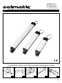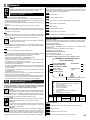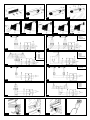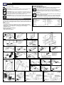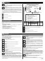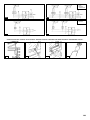
1
16000
• SISTEMI DI AUTOMAZIONE SINGOLI O IN BATTERIA PER SERRAMENTI A SPORGERE - AD ANTA A BILICO - A
LAMELLE SCORREVOLI - CUPOLE - VASISTAS - SISTEMI DI EVACUAZIONE FUMO
• SINGLE AND MULTIPLE OPENERS FOR OVERHANGING, BASCULE WING AND SLIDING PANEL FRAMES, SKY
LIGHTS AND TRANSOM WINDOWS, SMOKE REMOVAL
• SYSTEMES D’AUTOMATISATION SIMPLES OU EN BATTERIE POUR FENETRES À POUSSER - À BATTANT À
BALANCIER - À LAMELLES COULISSANTES - COUPOLES - VASISTAS - SYSTEMES D’EVACUATION FUMÉE
• AUTOMATISMOS SIMPLES O EN BATERÍA PARA CERRAMIENTOS EN SALIENTE – POR BATIENTE BASCULANTE – POR LÁMINAS CORREDERAS – LUCERNARIOS – VENTANAS CON ELECTROMONTANTES – SISTEMAS DE EVACUACIÓN DE HUMOS
ELETTROWASISTAS
ELETTROWASISTAS - BATT/AP-EST
ELETTROWASISTAS - BATT/AP-INT
• Sistemi di automazione per finestre a wasistas
• Vista di una installazione del sistema elettromeccanico elettrowa- • Vista di una installazione di un sistema elettrowasistas in batsistas per aprire max 20 sportelli in batteria - il movimento viene teria su finestre con apertura verso l’interno
• Automation system for overhanging and bascule windows
• Systèmes d’automatisation pour fenêtre à wasistas, cupoles trasmesso ai bracci a cremagliera attraverso la rotazione di un • An battery elettrowasistas system with rotating tube and rack
etc. etc.
• Automatismos para ventanas y electromontantes
ELETTROWASISTAS/BATT
tubo orizzontale
arms
• Installation example of the electromechanical multiple vasistas • Vue d’une installation d’un système électromécanique électro-
transom window system of up to 20 windows - the motion is transmitted to the rackwork arm by a horizontal rotating tube
• Vue d’une installation du système électromécanique électrovasistas
pour ouvrir max 20 fenêtres en batterie - le mouvement est transmis
aux bras à crémaillère à travers la rotation d’un tube horizontal
• Vista de una instalación electromecánica de electromontantes
para abrir un máximo de 20 ventanas en batería – el movimiento se transmite a los brazos por cremallera a través de la
rotación de un tubo horizontal
16010 - GIUN/TAM-TUBO
vasistas en batterie pour des fenêtres ouvrant vers l’interieur
• Vista de una instalación de un sistema de electromontantes en
batería sobre ventanas con apertura hacia el interior
16020 - TUB/D33
• Elettrowasistas in batteria - sistema di automazione per max • Giunto di collegamento TAM-Tubo - NB. per un completo col- • Tubo orizzontale D33 - spezzoni da mt 2 - zincato e lavorato
20 finestre a vasistas. Il rif. 22010 è il motoriduttore in grado di
azionarle - (TAM)
• Electrowasistas in group - automatic system for max 20 wasistas windows - operated by 22010 gearmotor (TAM)
• Electrovasistas en batterie - système d’automatisation pour
max 20 fenêtres à balancier. La réf. 22010 est le motoréducteur
adapté pour les actionner - (TAM)
• Electromontantes en batería – automatismo para un máximo
de 20 ventanas por montantes - el artículo con ref. 22010 es el
motorreductor capaz de ponerla en marcha - (TAM)
legamento prevedere 1 pezzo del rif. 16070 giunto tubo/tubo
- tagli per chiavetta e foratura per bulloni giunto tubo/tubo rif.
plète, prévoir 1 pièce réf. 16070 joint tube/tube
16070
solicitar una pieza de la ref. 16070 junta tubo/tubo
encoches pour clavette et trou pour boulons joint tube/tube réf.
16070
• Tubo horizontal de 33 – piezas de 2 m. – galvanizado y trabajado – muescas para clavija y pernos de la junta tubo-tubo
ref. 16070
• Connection coupling TAM-Tube for full connection use one 16070
piece rif. 16070 tube/tube coupling
• Horizontal tube D33 - tubes in 2 m lengths - galvanized and
• Joint de connexion TAM-Tube - NB. pour une connexion com- processed - key cuts and holes for coupling bolts tube/tube ref
• Junta de unión TAM/tubo –NB. para una conexión completa • Tube horizontal D33 - morceaux de 2m - zingué et usiné -
69
16030 - MENS-C/D33
16040 - MENS/D33
16050/60 - BR/CREM
• Mensola zincata con cuscinetto in plastica - si impiega nei • Mensola semplice - si impiega nei sistemi in batteria fino a 10 • Braccio a cremagliera da mt. 1 senza compensatore (rif.
sistemi in batteria sopra a 10 finestre a vasistas - 1 mensola
ogni 2 mt. di tubo
• Galvanized bracket with plastic bearing - used on group
systems of 10 transoms windows or over - 1 bracket for each 2
m. tube
• Support zingué avec coussinet en plastique - s’utilise dans les
systèmes en batterie au-dessus de 10 fenêtres à vasistas - 1 support tous les 2m de tube
• Soporte galvanizado con cojinete de plástico – se utiliza en
los sistemas en batería con más de 10 ventanas con montantes
– un soporte cada 2 m. de tubo
16070 - GIUNT/TUBO-TUBO
• Giunto tubo-tubo D33
• Tube-tube joint D33
• Joint tube-tube D33
• Junta tubo-tubo D33
finestre a vasistas - 1 mensola ogni 2 mt. di tubo
• Simple bracket used on group systems up to 10 transom windows - 1 bracket for each 2 m. tube
• Support simple - s’utilise dans les systèmes en batterie jusqu’à
10 fenêtres à vasistas - 1 support tous les 2m de tube
• Soporte simple – se utiliza en los sistemas en batería de hasta
10 ventanas de montantes – un soporte cada 10 m. de tubo
16020+16030+16070
16050), con compensatore a spingere (rif. 16060) - per sportelli di L. superiore a mt. 1, utilizzare 2 bracci
• 1 m trimmer-less rackwork arm without trimmer (ref. 16050),
with push trimmer (ref. 16060) - use 2 arms for windows longer
than 1 m
• Bras à crémaillère de 1 m sans compensateur (réf. 16050),
avec compensateur à pousser (réf. 16060) - pour fenêtres de L.
supérieure à 1 m, utiliser 2 bras
• Brazo de cremallera de 1 metro sin compensador (ref.
16050) – con compensador por empuje (ref. 16060) – para
ventanas de más de 1 m. – utilizar 2 brazos.
D4
• Vista d’insieme del tubo, della mensola e del giunto di riac- • Pistone lineare per finestre a wasistas singolo - alim.
coppiamento
• Overall view of the tube, the bracket and the tube-tube joint
• Vue d’ensemble du tube horizontal D33, du support avec
coussinet et du joint tube-tube
• Vista global de tubo, soporte y de la junta tubo-tubo
230V/50 Hz forza 200 N - corse 105-180-300
• Linear piston for single vasistas transom windows - 230V./50
Hz - 200 N - 105-180-300 mm. strokes
• Vérin linéaire pour fenêtres à vasistas simples - alim.
230V/50 Hz - force 200 N - courses 105-180-300
• Pistón lineal para ventanas o montantes simples – alimentación 230 V/50Hz – fuerza 200 N – carrera 105-108-300 mm.
16078/9 - D6
16082 - M312
M312
• Pistone lineare per finestre a vasistas singole - alim. 230V/50Hz • Pistone lineare per finestre a wasistas singolo - alim. • Vista di installazione dell’operatore M312 su finestra con
- 150W/0,7 A - forza 450N - corse 160-180-235-300 mm. velocità di trasmissione 24 mm/sec - fine corsa automatico
• Linear piston for single vasistas transom windows - 230V/50Hz
power supply - 150W/0,7A power - 450N torque 160/180/235/300 mm stroke - 24 mm/sec actuator rod speed automatic limit switch
• Vérin linéaire pour fenêtres à vasistas simples - alim. 230/50Hz
- 150W/0,7 A - force 450N - course 160-180-235-300 mm vitesse de transmission 24 mm/s - fin de course automatique
• Pistón lineal para ventanas con montantes simples – alimentación 230 V/50 Hz – 150 W/0,7 A – fuerza 450 N – carrera
160-180-235-300 mm. –velocidad de transmisión 24 mm/seg.
– fin de carrera automático
70
230V/50 Hz - 450 N - corsa 300 mm.
apertura verso l’esterno
• Linear piston for single vasistas transom windows 230V./50 • An operator M312 installation
Hz - 450 Nm - 300 mm. stroke
• Vue d’une installation de l’operateur M312 sur des fenêtres
• Vérin linéaire pour fenêtres à vasistas simples - alim. ouvrant vers l’exterieure
230V/50 Hz - force 450 N - course 300 mm.
• Vista de la instalación del mecanismo M312 en ventana con
• Pistón lineal para ventanas con montantes simples –alimenta- apertura hacia el exterior
ción 230 V/ 50 Hz – fuerza 450 N – carrera 350 mm.
M312
16083/87/89/98/105 - EURO 1
16112/14/18/19 - D20
24V. corse 200-300-500 mm. fine corsa automatico
- W250/1,3 A - forza 600N - corse 180-225-300-500 - velocità
di traslazione 24 mm/sec - fine corsa automatico
• Linear piston for single vasistas transom windows - 230V/50Hz
power supply - 250W/1.3A power - 600N torque 180/225/300/500 mm adjustable stroke - 24 mm/sec actuator
rod speed - automatic limit switch
• Vérin linéaire pour fenêtres à vasistas simples - alim. 230V/50Hz
- W250/1,3 A - force 600N - courses 180-225-300-500 - vitesse
de translation 24 mm/s - fin de course automatique
• Pistones lineales para ventanas con montantes simples – alim.
230V/50Hz- 250W/1,3 A - fuerza 600 N. – carreras 180225-300- 500 – velocidad de traslación 24 mm./seg. – fin de
carrera automático
• Vista di installazione dell’operatore M312 su cupola e di N°2 • Pistoni lineari per finestre a vasistas singole - alim. 230V. o • Pistone lineare per finestre a vasistas singole - alim. 230V/50Hz
M312 in serie su finestre a sporgere verso l’esterno
• Linear pistons for single vasistas transom windows - 230V. or
• An operator M312 installation
24V. 200/300/500 mm. adjustable strokes - automatic limit
• Vue d’installation de l’operateur M312 sur une coupole e de switch
n°2 M312 en série sur une fenêtre ouvrant vers l’exterieure
• Vérin linéaire pour fenêtres à vasistas simples - alim. 230V or
• Vista de la instalación del mecanismo M312 en lucernario y 24V. - course 200-300-500 mm. - fin de course reglable
• Pistones lineales para ventanas o montantes simples – alim.
de N°2 M312 en serie sobre ventanas hacia el exterior
230V. o 24V. – carreras 200-300-500 mm. – fin de carrera
automático
16125/30 - D31
16135/6/7 - MICRO 92
MICRO S
• Pistone lineare per finestre a vasistas singole - alim. 230V/50Hz • Attuatore elettrico a catena per finestre a vasistas singole - alim. • Attuatore elettrico a catena per finestre a wasistas singole -
- W330/1,5 A - forza 2000N - corse 180-300-400-500 - velocità
di traslazione 19 mm/sec - fine corsa automatico
• Linear piston for single vasistas transom windows - 230V/50Hz
power supply - 330W/1.5A power - 2000N torque 180/300/400/500 mm adjustable stroke - 19 mm/sec actuator
rod speed - automatic limit switch
• Vérin linéaire pour fenêtres à vasistas simples - alim.
230V/50Hz - W330/1,5 A - force 2000N - courses 180-300400-500 - vitesse de translation 19 mm/s - fin de course automatique
• Pistones lineales para ventanas con montantes simples – alim.
230V/50Hz- 330W/1,5 A - fuerza 2000 N. – carreras 180300-400-500 – velocidad de traslación 19 mm./seg. – fin de
carrera automático
MICRO L
230V/50Hz - a richiesta 24V.cc. - W150/40 - A/0,65-1,7 - forza
150/300N - fine corsa automatico - corse 130-250-380 mm
• Electric chain actuator for single vasistas transom windows 230V/50Hz power supply - 24V CC power supply available on
request - 150/40W 0.65/1.7A power - 150/300N torque 130/250/380 mm adjustable stroke - automatic limit switch
• Actionneur électrique à chaîne pour fenêtres à vasistas simples alim. 230V/50Hz - sur demande 24 V.cc. - W150/40 - A/0,651,7 - force 150/300N - fin de course automatique - courses 130250-380 mm
• Mecanismo eléctrico en cadena para ventanas con montantes
simples – alim. 230V/50Hz – por encargo 24V.cc. - 150W/40
– A/0,65 - 1,7 - fuerza 130/300 N. – fin de carrera automático – carreras 130-250-380
16138/39/45/46 - MICRO XL
alim. 230V. o 24V. - 200 N corse 200-250 mm.
• Electric chain actuator for single vasistas transom windows
power supply 230V. or 24V. - 200N - 200-250 mm. strokes
• Operateur électrique à chaine pour fenêtres à vasistas simples
- alim. 230V or 24V - force 200 N - courses 200-250 mm.
• Mecanismo eléctrico en cadena para ventanas con montantes
simples – alim. 230V o 24V. - fuerza 200 N. – carreras 200250 mm.
16155 - ST/92
• Attuatore elettrico a catena per finestre wasistas singolo alim. • Attuatore elettrico a catena per finestre a vasistas singole - alim. • Staffa per applicazioni a vasistas (per Micro 92)
230/50Hz - a richiesta 24V.cc. (16145) - W150/0,7A - forza • Transom window hanger (for Micro 92)
230V. o 24V. - 350 N corse 280-380 mm.
• Electric chain actuator for single vasistas transom windows - 400N - fine corsa automatico - corse 420-600 mm.
Etrier pour applications à vasistas (pour Micro 92)
• Electric chain actuator for single vasistas transom windows - •
230V. or 24V. - 350N - 280-380 mm. strokes
• Soporte para montantes (para Micro 92)
• Operateur électrique à chaine pour fenêtres à vasistas simples 230V/50Hz power supply - 24V CC power supply (16145) availa- alim. 230V or 24V - force 350 N - courses 280-380 mm.
• Mecanismo eléctrico en cadena para ventanas con montantes
simples – alim. 230V o 24V. - fuerza 350 N. – carreras 280380 mm.
ble on request - 150W 0.7A power - 400N torque - 420/600 mm
adjustable stroke - automatic limit switch
• Actionneur électrique à chaîne pour fenêtres à vasistas simples alim. 230V/50Hz - sur demande 24 V.cc. (16145) - W150/0,7A force 400N - fin de course automatique - courses 420-600 mm.
• Mecanismo eléctrico en cadena para ventanas con montantes
simples – alim. 230V/50 Hz por encargo 24V.cc. (ref. 16145)
– 150 W/0,7 A. - fuerza 400 N. –fin de carrera automático carreras 420- 600 mm.
71
16157 - ST-SPUR/X
• Kit universale per applicazioni a sporgere per Micro XL
• Universal overhanging windows (for Micro XL)
• Kit universel pour applications à pousser (pour Micro XL)
• Kit universal para aplicaciones que sobresalen para Micro XL
16162/64/66/69/70/76 - ACK 42
16159 - ST-V/XL
16160 - KIT ELETTROWASISTAS MICRO 92
• Kit universale per applicazioni a vasistas (per Micro XL)
• Universal vasistas transom window kit (for Micro XL)
• Kit universel pour applications à vasistas (pour Micro XL)
• Kit universal para aplicaciones por montantes para Micro XL
• N°1 - 16135 Micro 92
ACK 42
N°1 - 16155 Staffa per applicazioni a vasistas
N°1 - 32180 Pulsantiera PiR2
• N°1 - 16135 Micro 92
N°1 - 16155 vasistas transom window
N°1 - 32180 PiR2 push-button panel
• N°1 - 16135 Micro 92
N°1 - 16155 Etrier pour application à vasistas
N°1 - 32180 Bouton poussoir PiR2
• N°1 16135 Micro 92
N°1 16155 soporte para aplicación de montantes
N°1 32180 botonera PiR2
ACK 42
• Attuatore elettrico a catena per finestre a vasistas singole - • Esempi di installazione dell’operatore ACK 42
alim. 230V. o 24V. - 350 N - fine corsa reg. 100-150-200- • An ACK 42 installation
250-300-305-400 mm.
• Examples d’applications de l’operateur ACK 42
• Electric chain actuators for single vasistas transom windows • Ejemplos de instalación del sistema ACK42
• Esempi di installazione dell’operatore ACK 42
• An ACK 42 installation
• Examples d’applications de l’operateur ACK 42
• Ejemplos de instalación del sistema ACK42
16185 - ST LAT
16640/42/44/46/48/50 - SERVER
230V. or 24V. - 350N - 100-150-200-250-300-305-400 mm.
adjustable limit switch
• Operateur électrique à chaine pour fenêtres à vasistas simples
- alim. 230V or 24V - force 350 N - 7 regulations de fin de
course 100-150-200-250-300-305-400 mm.
• Mecanismo eléctrico en cadena para ventanas con montantes
simples – alim. 230V o 24V. - fuerza 350 N. – fin de carrera
automático - carreras100-150-200-300-305-400 mm.
• Staffe laterali per ACK 42
• Lateral supports for ACK 42
• Supports laterals por ACK 42
• Soportes laterals para ACK 42
72
16550/52/54/56/58/60 - S1
• Attuatori elettrici a cremagliera per finestre a vasistas e scor- • Gruppo cremagliera con staffa da installare in parallelo con
revoli - alim. 230V./600 N o 24V./200 N - corse 180-230350-550-750-1000 mm. - velocità 8 mm. sec o 14 mm. sec.
• Electric rack actuators for single vasistas transom or sliding
windows - 230V./600N or 24V./200N - 180-230-350-550750-1000 mm. strokes - 8 mm. or 14 mm. sec. speed
• Operateurs électriques à crémaillère pour fenêtres à vasistas
et coulissantes - alim. 230V/50 Hz - force 600 N - alim. 24V. force 200 N courses 180-230-350-550-750-1000 mm. - vitesse 8 mm./sec. or 14 mm./sec.
• Mecanismos eléctricos por bisagra para ventanas con montantes correderos – alim. 230V/600N o 24V/200 N. - carreras 180-230- 350- 550- 750- 1000 mm. – velocidad 8
mm./seg. o 14mm./seg.
l’operatore S1 - corse 180-230-350-550-750-1000 mm.
• Rack assembly for connection S1 in tandem - 180-230-350-
550-750-1000 mm. strokes
• Unité à cremaillère à installer en parallel avec l’operateur S1
- courses 180-230-350-550-750-1000 mm.
• Conjunto de bisagra con soporte para instalar en paralelo
con el mecanismo S1 - carreras 180-230- 350- 550- 7501000 mm
16660/62/64/66/68 - TUBO COLL
16690/92 - PM-10M
16704/6 - RIL FUM
• Gruppo tubo di collegamento tra Server e S1 - L. 1000/1250 • Centrale di comando per 10 operatori 24V. (senza batterie) •
1500/1750/2000 mm.
16690 + rilevazioni (16692)
•
• Connection Rod. Server/S1 L.1000/1250/1500/1750/2000 • Control unit for 10 motors 24V. (without batteries) 16690 +
•
mm.
Detection (16692)
• Tube de raccordement entre le S1 et le ser ver - L. • Programmateur de commande simultanée pour 10 operateurs •
1000/1250/1500/1750/2000 mm.
• Conjunto tubo para unir Ser ver
1000/1250/1500/1750/2000 mm.
y
S1
–
L.
Rilevatore di fumo ottico 2 fili
Optical smoke detector - 2 wires
Détecteur de fumée optique 2 fils
Detector óptico de humos (2 cables)
24V. - sans les batteries - (16690) - plus les detections (16692)
• Centralita para 10 mecanismos 24V. (sin pilas) 16690 +
detectores (16692)
16712 - MOD EVAC. FUMO
16714 - SCH. INT. PIOG/VENT
• Modulo di evacuazione fumo
• Smoke discharge module
• Module additionnel pour l’évacuation de la fumée
• Módulo adicional para la evacuación de humos
• Scheda interfaccia per rilevatori pioggia e vento
• Interface for wind and rain detectors
• Module interface pour les detecteurs de pluie et vent
• Tarjeta interface para detectores de lluvia y viento.
73
Via dei Gonzaga, 147
00163 Roma - Italy
Tel. +39-0666141555 r.a
Fax +39-0666154762
E-mail: [email protected]
®
EURO 1
• APPLICAZIONI • APPLICATIONS • APPLICATIONS • APLICACIONES • ANWENDUNGSMÖGLICHKEITEN
AA
AB
BA
BB
CA
75
ITALIANO
Prima di intraprendere qualsiasi operazione di installazione o collegamento elettrico, si raccomanda di leggere con estrema attenzione questo manuale.
L'utilizzatore è tenuto a prendere visione delle note in esso riportate e a
conservarlo per eventuali ulteriori consultazioni.
• I profili e i fissaggi siano adeguatamente dimensionati per sopportare le sollecitazioni prodotte dall'azionamento.
DEFINIZIONE DEI SIMBOLI
• Gli impianti elettrici di comando siano conformi alle norme vigenti nel proprio paese.
Leggere attentamente questo manuale.
• I tipi di cerniere o ferramenta utilizzati, consentano la completa corsa di
apertura dell'attuatore al fine di evitare danni alle strutture provocati dalla
forza di trazione o di spinta dell'attuatore.
• I cavi di alimentazione degli attuatori siano di sezione sufficiente.
• La rete di alimentazione e di comando sia in prossimità del serramento.
Pericolo!
Pericolo derivante da rischio di folgorazione da corrente elettrica.
Pericolo!
Indicazione di un pericolo che potrebbe causare lesioni alle persone.
Pericolo!
Pericolo di schiacciamento delle mani.
Attenzione!
Evidenzia note da tenere in considerazione per evitare danni all'attuatore.
Informazione.
Si riferisce a informazioni importanti alle quali prestare attenzione.
NOTE RELATIVE ALL'ATTUATORE
L'attuatore EURO1 è conforme alle normative vigenti. La garanzia per
un funzionamento sicuro è legata al rispetto da parte degli installatori delle norme di sicurezza in vigore nel proprio paese.
L'attuatore EURO1 è destinato esclusivamente all'apertura e alla chiusura di
finestre a sporgere, lucernai e finestre a lamelle ed è destinato al solo uso interno. L'uso dell'attuatore per altre applicazioni deve essere autorizzato dalla
Saimatic S.r.l., previo verifica tecnica dell' applicazione.
Installare l'attuatore utilizzando esclusivamente accessori originali o approvati dalla Saimatic S.r.l.
• Sia presente la scatola di derivazione nella quale attestare i conduttori del
cavo di alimentazione.
• L'imballo contenga tutti i componenti e accessori previsti per l'installazione
dell'attuatore (A00-B00-C00).
• Applicando tensione all'attuatore il funzionamento sia regolare e uniforme
e intervengano correttamente i due fine corsa che limitano la corsa minima
e massima dello stelo.
• Durante le operazioni di montaggio e/o smontaggio dell'attuatore dal serramento, essendo questo non bloccato nella posizione aperta o chiusa, vengano adottati opportuni accorgimenti per prevenire sbattimenti accidentali
con urti e possibili rotture del serramento e lesioni all'operatore.
• Sia previsto un ponteggio o un'impalcatura se gli attuatori debbono essere
installati ad una altezza superiore a 2,5 metri.
Operazioni da eseguire prima di montare l'attuatore
• Alimentare l'attuatore ed effettuare una corsa a vuoto, per assicurarsi che
durante il trasporto non abbia subito danni.
A
DESCRIZIONE MONTAGGIO SU FINESTRA A
SPORGERE E CUPOLE
A01
• Individuare e tracciare la mezzeria del serramento e del telaio fisso.
• Tracciare i fori di fissaggio riferendosi alla staffa in dotazione.
• Eseguire i fori sul serramento e sul bancale (o telaio) usando le punte appropriate, per poter montare la staffa attacco anteriore e la staffa supporto
motore.
A02
IMPORTANTI ISTRUZIONI PER LA SICUREZZA
Attenzione!
È importante per la sicurezza delle persone, seguire fedelmente
tutte le istruzioni di seguito riportate.
• Fissare la staffa attacco anteriore (2) con le viti (20) al serramento senza
serrare a fondo.
• Fissare la staffa supporto motore (1) con le viti (24) e serrare a fondo.
• Allineare la staffa porta motore (1) alla staffa attacco anteriore (2) e serrare le viti di fissaggio (20).
USO E MANUTENZIONE
Durante l'uso dell'attuatore EURO1 è bene osservare le seguenti norme di
comportamento:
A03
non consentire ai minori di giocare con il comando a distanza;
controllare visivamente le parti in movimento e non consentire alle
persone e ai minori di avvicinarsi fino al completo arresto del movimento;
A04
controllare visivamente almeno una volta all'anno che il conduttore
di alimentazione non risulti essere danneggiato e che non siano
presenti altri segni di usura o danneggiamenti;
controllare che nessun oggetto ostacoli il movimento del serramento;
non effettuare mai in caso di guasto interventi sull'attuatore, non
aprire o smontare parti dell'attuatore che impediscano l'accesso all'interno del meccanismo.
In caso di guasti o danni all'apparecchio rivolgersi a personale specializzato,
non utilizzare l'attuatore fino a che non sia stato riparato.
INSTALLAZIONE
Personale tecnico preposto alla installazione.
Le operazioni di montaggio e di collegamento elettrico dell'attuatore
EURO1 debbono essere eseguite da personale specializzato dotato di
adeguata preparazione professionale e conoscenze specifiche sulle
problematiche della motorizzazione dei serramenti, delle normative tecniche di riferimento e delle norme antinfortunistiche.
Attenzione!
Un'installazione non corretta può rendere l'attuatore pericoloso.
Seguire tutte le istruzioni di seguito riportate.
Verifiche
Prima di procedere alla installazione verificare che:
• Le prestazioni dell'attuatore siano sufficienti alla movimentazione del serramento (evitando il superamento dei limiti indicati sulla targa dell'attuatore)
considerando che sul serramento, soprattutto se si tratta di un lucernaio, oltre al carico prodotto dal vento può gravare anche il carico dovuto alla neve ed eventuali formazioni di ghiaccio.
• L'altezza minima del serramento sia superiore a 300 mm (finestre a sporgere e cupole).
76
• Inserire i dadi a coda di rondine (3b) nelle guide ricavate sui fianchi dell’attuatore (EURO1) e portarli in prossimità della parte anteriore.
• Inserire l’attuatore all’interno della staffa (1).
• Inserire i fissaggi laterali (3) nei fori della staffa (1) e centrarli sulle guide a
coda di rondine (3b).
• Inserire le viti (7) quindi bloccarle senza serrare a fondo.
A05
• Con il serramento chiuso e l’attuatore a fine corsa (chiuso) posizionare il
tutto in modo che la testina “A” si inserisca all’interno della staffa di attacco (2).
• Inserire la vite (6) e bloccare con dado (8).
A06
• Spostare l’attuatore lungo il proprio asse per poter esercitare una sufficiente pressione sulle guarnizioni del serramento.
• Stringere a fondo le viti (7) all’interno dei fissaggi laterali (3).
A07
• Collegare l’attuatore all’impianto elettrico servendosi degli schemi allegati,
rispettando le norme di sicurezza vigenti in materia.
• Effettuare, se necessario, la regolazione della corsa procedendo come segue:
1) Alimentare l’attuatore fino a determinare l’uscita completa dello stelo. Rimuovere, svitandola, la protezione (31) a vite.
2) Svitare con una chiave esagonale di 2,5mm il grano esagonale di M5
(32) allentandolo di un solo giro.
3) Alimentare l’attuatore fino a portare lo stelo nella posizione voluta corrispondente alla corsa desiderata B. Durante questa fase mantenere la
chiave in posizione sul grano (32) e procedere allo spostamento dello stelo a piccoli tratti, per evitare che la chiave possa bloccarsi all’interno del foro filettato.
4) Raggiunto il valore desiderato, stringere moderatamente il grano esagonale.
5) Rimontare la protezione a vite (31).
• Alimentare l’attuatore per fare rientrare lo stelo. Le corse successive si arresteranno sempre nel punto scelto con la regolazione.
• Azionare l’attuatore per aprire il serramento, arrivare a fine corsa e richiu-
ITALIANO
dere. Questo per verificarne il corretto funzionamento.
• Se necessario, ripetere la procedura sopra descritta per la regolazione.
Attenzione !
Lo stelo non può ruotare, evitare operazioni che forzino questa
condizione.
Pericolo !
Pericolo di schiacciamento delle mani. Durante il movimento del battente non interporre le mani fra il telaio fisso e lo stesso battente.
B
DESCRIZIONE MONTAGGIO SU FINESTRA A LAMELLE
SENZA BLOCCO MECCANICO E PALE FRANGISOLE
• L’attuatore EURO1 viene fornito predisposto per la massima corsa effettuabile per modello. Se il serramento a lamelle richiede una corsa minore
di quella indicata in targa, procedere prima del montaggio meccanico ad
una regolazione di massima portando la corsa ad un valore leggermente
inferiore a quello necessario come descritto in A07.
B01
cedere allo spostamento dello stelo a piccoli tratti, per evitare che la chiave possa bloccarsi all’interno del foro filettato.
4) Raggiunto il valore desiderato, stringere moderatamente il grano esagonale.
5) Rimontare la protezione a vite (31).
• Alimentare l’attuatore per fare rientrare lo stelo. Le corse successive si arresteranno sempre nel punto scelto con la regolazione.
• Azionare l’attuatore per aprire il serramento, arrivare a fine corsa e richiudere. Questo per verificarne il corretto funzionamento.
• Se necessario, ripetere la procedura sopra descritta per la regolazione.
B01F
• Portare le lamelle del serramento o le pale frangisole in posizione di chiusura agendo manualmente sui bracci G.
B02
• Portare la testina A dell’attuatore al centro dei due bracci G, inserire il perno (10) e bloccarlo con i dadi (11).
B02F
• Portare la testina A dell’attuatore in corrispondenza del foro del braccio G,
inserire il perno (10) e bloccarlo con i dadi (11).
B03 B03F
• Inserire i dadi a coda di rondine (3b) nelle apposite guide ricavate sui fianchi dell’attuatore e portarle in prossimità della parte posteriore.
B04 B04F
• Inserire l’attuatore all’interno della staffa (1).
• Inserire i fissaggi laterali nei fori della staffa e centrarli sulle guide a coda di
rondine (3b).
• Inserire le viti (7) quindi bloccarle serrando a fondo.
Pericolo !
Pericolo di schiacciamento delle mani. Durante il movimento del battente non interporre le mani fra il telaio fisso e lo stesso battente.
C
C01
• Tracciare la mezzeria del serramento.
• Realizzare le forature riferendosi alle misure riportate nel disegno, tenendo
presente che le quote espresse sono specifiche per i prodotti GEZE OL 90
e GEZE OL 100.
• Montare sul telaio fisso la forbice equipaggiata dall’asta di movimento (non
in dotazione).
• Montare sull’anta mobile l’attacco per la forbice K (non fornito).
C02
• Applicare la staffa a coda di rondine (18) in dotazione all’attuatore fissandola saldamente al telaio fisso ed inserirvi l’attuatore lasciandolo momentaneamente libero sulla staffa stessa.
C03
• Inserire sull’asta di movimento l’accessorio (19) 2E9101 per OL 90 o
2E9102 per OL 100 avendo cura di verificare che la distanza x corrisponda alla corsa necessaria al funzionamento della forbice.
Attenzione !
L’attuatore è sempre fornito con una corsa regolata a 55 mm per
OL90 e 80 mm per OL 100.
B05
• Mantenendo le lamelle chiuse, posizionare la staffa contro la parete verticale del serramento.
• Verificare che l’asse dell’attuatore sia al centro dei braci e perpendicolare
al perno di collegamento (10).
• Tracciare, usando come riferimento il foro accessibile della staffa supporto
motore.
• Forare con punta adeguata il foro tracciato precedentemente e fissare la
staffa attacco motore con vite (non fornita) avvitando a fondo.
B05F
• Mantenendo i frangisole chiusi, posizionare la staffa contro la parete verticale del serramento.
• Verificare che l’asse dell’attuatore sia parallelo al braccio e perpendicolare
al perno di collegamento (10).
• Tracciare, usando come riferimento i fori accessibili della staffa supporto
motore.
• Forare con punta adeguata il foro tracciato precedentemente e fissare la
staffa attacco motore con vite (non fornita) avvitando a fondo.
B06 B06F
• Svitare le viti (7), togliere i fissaggi laterali (3), i dadi (11), il perno (10) e rimuovere l’attuatore.
B07 B07F
• Usando la staffa supporto motore come maschera di foratura, effettuare la
foratura dei due fori rimasti, inserire le viti (non fornite) e avvitarle a fondo.
B08 B08F
• Reinserire il perno (10) bloccandolo con i dadi (11) serrati a fondo.
• Inserire i fissaggi laterali nei fori della staffa attacco motore centrandoli sui
dadi a coda di rondine (3b).
• Inserire le viti (7) quindi bloccarle serrandole a fondo.
DESCRIZIONE MONTAGGIO IN ABBINAMENTO A FORBICI
TIPO GEZE
C04
• Fissare saldamente l’accessorio (19) 2E9101 o 2E9102 all’asta di movimento mediante le apposite viti (21) e con la vite M6x16 (20) in dotazione
all’estremità dello stelo dell’attuatore.
C05
• Serrare le viti di espansione (22) poste sulla staffa (18).
C06
• Collegare l’attuatore all’impianto elettrico servendosi degli schemi allegati,
rispettando le norme di sicurezza vigenti in materia.
• Effettuare, se necessario, la regolazione della corsa procedendo come segue:
Alimentare l’attuatore fino a determinare l’uscita completa dello stelo.
1) Rimuovere, svitandola, la protezione (31) a vite.
2) Svitare con una chiave esagonale di 2,5 mm il grano esagonale di M5
(32) allentandolo di un slo giro.
3) Alimentare l’attuatore fino a portare lo stelo nella posizione voluta corrispondente alla corsa desiderata B.
Durante questa fase mantenere la chiave in posizione sul grano (32) e procedere allo spostamento dello stelo a piccoli tratti, per evitare che la chiave possa bloccarsi all’interno del foro filettato.
4) Raggiunto il valore desiderato, stringere moderatamente il grano esagonale.
5) Rimontare la protezione a vite (31).
• Alimentare l’attuatore per fare rientrare lo stelo. Le corse successive si arresteranno sempre nel punto scelto con la regolazione.
• Azionare l’attuatore per aprire il serramento, arrivare a fine corsa e richiudere. Questo per verificarne il corretto funzionamento.
• Se necessario, ripetere la procedura sopra descritta per la regolazione.
B09 B09F
• Si consiglia di montare tra la testina A e i bracci G del serramento dei distanziali (non forniti) di lunghezza appropriata per garantire l’allineamento dell’attuatore.
B10 B10F
• Collegare l’attuatore all’impianto elettrico servendosi degli allegati, rispettando le norme di sicurezza vigenti in materia.
• Effettuare la regolazione della corsa procedendo come segue:
Alimentare l’attuatore fino a determinare l’uscita completa dello stelo.
1) Rimuovere, svitandola, la protezione (1) a vite.
2) Svitare con una chiave esagonale di 2,5 mm il grano esagonale di M5
(2) allentandolo di un solo giro.
3) Alimentare l’attuatore fino a portare lo stelo nella posizione voluta corrispondente alla corsa desiderata B.
Durante questa fase mantenere la chiave in posizione sul grano (32) e pro-
D
ISTRUZIONI PER L’ALLACCIAMENTO ALLA
RETE ELETTRICA
Queste istruzioni di allacciamento alla rete elettrica di alimentazione
sono rivolte esclusivamente a personale specializzato e abilitato alla
esecuzione di impianti elettrici il quale si dovrà sempre attenere alle
norme e alle leggi vigenti in materia di installazioni elettriche.
Pericolo !
Al fine di evitare il pericolo di folgorazione da corrente elettrica togliere l’alimentazione alla linea di comando prima di eseguire dei
lavori sugli attuatori o sull’impianto. Installare sempre a monte della linea di
comando dell’attuatore un interruttore generale di alimentazione omnipolare
con apertura minima dei contatti pari a 3 mm.
77
ITALIANO
Pericolo !
Pericolo di schiacciamento delle mani. Durante il movimento del battente non interporre le mani fra il telaio fisso e lo stesso battente.
Attenzione !
Se l’apertura del serramento è limitata da accessori di sicurezza o
è inferiore alla corsa dell’attuatore, potrebbero prodursi danni all’attuatore o al serramento.
Attenzione !
Prevedere l’installazione di due pulsanti interbloccati, normalmente aperti, con comando del tipo ad “uomo morto” o equivalente.
L’allacciamento alla rete si effettua utilizzando un cavo a 4 conduttori (4x1
mm2) di lunghezza sufficiente a raggiungere la scatola di connessione che
deve essere posta in prossimità dell’attuatore.
Si consiglia di installare gli eventuali controlli remoti in posizione tale che
l’automazione comandata sia visibile e ad un’altezza minima di 1,5 m.
Se l’attuatore è previsto per un funzionamento senza sorveglianza (funzionamento automatico o a distanza) è opportuno installare dei dispositivi di sicurezza addizionali.
Dati di identificazione presenti sulla targa dell'attuatore
Saimatic Srl - 00163 Roma - Italy
Attuatori Elettrici
A
B
Tipo: 1E96200140N00
Nr: N1002326
F
G
230V-50Hz 260W IP55
(att30W+lamp230W)
C
Forza: 450N
Corsa: 200 mm
H
D
Veloc.: 12 mm/s
max n.
E
E
175sON/175sOFF
Conforme alle direttive 73/23/CEE 93/68/CEE e 89/336/CEE
D01
• Collegamento singolo (vedi figura).
D02
A
B
• Collegamento di più attuatori (vedi figura).
D03
• Collegamento doppio con segnalazione e sincronizzazione (vedi figura).
C
D
E
F
G
D04
• Collegamento singolo con segnalazione (vedi figura).
D05
• Collegamento singolo (vedi figura).
D06
• Collegamento di più attuatori (vedi figura).
H
LEGENDA:
Tipo
Tensione di funzionamento Potenza assorbita
per il movimento
Forza di trazione e di spinta
Velocità di traslazione
Frequenza di utilizzo
N° matricola
Potenza assorbita per la segnalazione,
dove previsto
Corsa di apertura/chiusura
D07
• Collegamento singolo con segnalazione (vedi figura).
1E96
200
1
D08
• Collegamento doppio con segnalazione e sincronizzazione (vedi figura).
4
N°conduttori cavo
Famiglia Corsa Tensione 2 - 4 - 8
S - segnalazione
0
N
00
Varianti
Tipologia Colore personalizattacco
zate
DATI TECNICI
Settori di impiego
Apertura e chiusura elettrica a distanza di finestre a sporgere, lucernai, finestre a lamelle e pale frangisole presenti in edifici pubblici privati e industriali.
Particolarità dell'apparecchio
• finecorsa automatico al raggiungimento della posizione finale (aperto/chiuso)
• corse di apertura disponibili fra 200/500 mm
• chiusura fine regolabile.
Possibilità di comando dell'attuatore
• mediante commutatore manuale
• mediante centralina di rilevazione di vento e pioggia
ERRORI DA EVITARE
E01
L’attuatore non può ruotare per seguire l’apertura del serramento (vedi figura).
E02
Montaggio fuori asse dell’attuatore (vedi figura).
E03
Mancata o errata regolazione della corsa (vedi figura).
E04
Pulsantiera di comando a doppio pulsante non interbloccato (vedi figura).
ENGLISH
Before embarking on any installation or wiring operations, read this
manual extremely carefully.
The user must refer to the notes contained in it and keep it safely for
future reference.
EXPLANATION OF THE SYMBOLS
Read this manual carefully.
Danger!
Danger of electric shock.
NOTES ON THE ACTUATOR
The EURO1 actuator complies with current safety standards.
Operating safety can be guaranteed only if installers comply with the
safety regulations in force in the country in which the actuator is used.
The EURO1 actuator is designed exclusively to open and close top hung
windows, skylights and louvre windows and is designed only for indoor use.
Any other application of the actuator must by approved by Saimatic S.r.l., after technical testing of the application.
Use only original accessories or accessories approved by Saimatic S.r.l. to
install the actuator.
IMPORTANT SAFETY REGULATIONS
Danger!
Danger that could cause personal injury.
Danger!
Danger of hands being crushed.
Warning!
Draws attention to instructions that must be followed in order to prevent damage to the actuator.
Notice.
indicates important to which great attention must be paid.
78
Warning!
In order to ensure personal safety, strictly comply with the regulations that are set out below.
USE AND MAINTENANCE
When using the EURO1 actuator, follow these safety regulations:
do not allow children to play with the remote controls;
Observe the moving parts closely and allow neither adults or children
to approach until the moving parts have come to a complete stop;
at least once a year, check that the power cable has not been damaged and that it shows no sign of wear;
ENGLISH
check that no object obstructs the window movement;
if faults arise, never work on the actuator, never open or dismantle
parts of the actuator that deny access to the inside of the mechanism.
If the actuator fails to function or is damaged, contact service engineers; do
not use the actuator until it has been repaired.
INSTALLATION
Only qualified installers can carry out installation.
The EURO1 actuator must be assembled and wired up only by specialised staff who have been properly trained and who are familiar with the
problems connected with automatic window opening and closing systems, technical reference standards and safety standards.
Warning!
Incorrect installation may make the actuator dangerous! Follow all
the instructions set out below.
Checks
Before installing, check that:
• Actuator is sufficiently powerful to open and close the window (ensure that
the limits indicated are not exceeded). Remember that the window, especially if it is a skylight, may have to not only stand up to the wind but also
bear the weight of snow and perhaps of ice.
• The minimum height of the window is more than 300 mm (top hung windows
and dome windows).
• The frame components and hinges are of an adequate size to stand up to
the operating stress.
• The hinges and fixtures enable the actuator to complete its opening stroke
in order to prevent damages to structores due to the thrust or tensile stress
exterd by the actuator.
• The electrical control systems comply with the regulations in force in the
country of use.
• The actuator’s power cables are sufficiently wide in diameter.
• The mains power supply and main switch are near the window.
• There is a junction box to house the power cable conductors.
• The packing contains all the component parts and accessories required to
install the actuator (A00-B00).
• The actuator operates smoothly and correctly when the it is powered up and
the two limit switches are triggered in order to limit the minimum and maximum stroke of the rod.
• That during assembly and disassembly of the actuator from the window, as
it is not blocked in the open or closed position, appropriate measures are
taken to avoid any accidental banging with hits, breakages of the window
and injury to the operator.
• A platform or scaffolding is provided if the actuators are to be installed at a
height of more than 2,5 metres.
Operations that must be carried out before fitting the actuator.
• Power up the actuator and make it complete one stroke before fitting it in order to check that it has not been damaged during transit.
A
FITTING TO TOP HUNG WINDOWS
AND DOME WINDOWS
A01
• Find and mark the centre line of between the window and the fixed frame.
• Mark dusing the supplied braket as a reference.
• Drill holes in the window and on the sill (or frame), using the appropriate bits.
Next, fit the front bracket and the motor support bracket.
A02
• Fix the front bracket (2) with the screws (20) to the window without completely tightening the screws.
• Fix the bracket (1) with the screws (21) and tighten.
• Align the motor bracket (1) on the front bracket (2) and tighten the screws
(20).
A03
• Insert the dovetail nuts (3b) into the guides on the sides of the actuator (EURO1) and take them to the front.
A04
• Insert the actuator inside the bracket (1).
• Insert the side fixtures (3) into the bracket holes (1) and align them on the
dovetail guides (3b).
• Insert the screws (7) and then fix them without fully tightening them.
A05
• With the window closed and the actuator at the end of its stroke (closed),
position everything in such a way that head “A” can be inserted into the inside of the front bracket (2).
• Insert the screw (6) and fix with nut (8).
A06
• Move the actuator along its own axis so taht sufficient pressure is exerted
on the window seals.
• Tighten the screws (7) inside the side fixtures (3).
A07
• Connect the actuator to the mains supply as shown in the enclosed wiring
diagrams and in compliance with safety standards.
• To adjust the stroke, follow this procedure:
1) Run the actuator until the rod is fully extended.
2) Remove the guard (31) by unscrewing it.
3) Loosen the M5 hexagonal-head dowel (32) by just one turn of a 2,5 mm
Allen wrench.
Run the actuator until the rod is in the required position, which corresponds
to the required stroke B. During this phase, keep the allen wrench inserted
into the hexagonal-head dowel (32) and inch the rod along, so that the Allen wrench does not jam inside the threaded hole.
4) When the required value has been reached, tighten the hexagonal-head
dowel moderately.
5) Screw the guard (31) back into place.
• Run the actuator to make the rod fully retract.
Subsequent strokes will always stop in the position that was selected during adjusting.
• Switch on the actuator in order to open the window, wait until the end of
stroke is reached and close again. This operation tests that the actuator is
working correctly.
• If necessary, repeat the adjustment as above described.
Warning !
The rod cannot rotate. Make sure that you do not force the rod to
rotate.
Danger !
Danger of hands being crushed. When the window is moving, do
not insert your hand between the fixed frame and the window pane.
B
FITTING TO LOUVRE WINDOW WITHOUT MECHANICAL
STOP AND SUN BLINDS
• The EURO1 actuator is supplied with the maximum possible stroke for each model. If the louvre window requires a shorter stroke than that shown on
the ratings plate, first effect a rough adjustment by setting the stroke to a value that is slightly lower than the required one, as described in item A07,
then assemble.
B01
B01F
• Close the slats of the louvre window or sun blinds by manually operating
arms G.
B02
• Place head A of the actuator at the centre of the two arms G, insert pin (10)
and fix with nuts (11).
B02F
• Place head A of the actuator over the hole of arm G, insert pin (10) and fix
with nuts (11).
B03 B03F
• Insert the dovetail nuts (3b) in the guides in the sides of the actuator and
place them near the rear part.
B04 B04F
• Insert the actuator inside the bracket (1).
• Insert the side fixtures (3) into the bracket holes and align them on the dovetail guides (3b).
• Insert the screws (7) and then completely tighten them.
B05
• Keep the slats closed and place the bracket against the vertical wall of the
window.
• Ensure that actuator axis is at the centre of the arms and that it is perpendicular to the connecting pin (10).
• Mark, using the accessible hole of the motor support bracket
• Drill the previously marked hole with an appropriate bit and fix the motor
support bracket by completely tightening the screw (not supplied).
B05F
• Keep the slats closed and place the bracket against the vertical wall of the
window.
• Make sure that the axis of the actuator is parallel to the arm and that it is
perpendicular to the connecting pin (10).
• Mark, using the accessible holes of the motor support bracket
• Drill the previously marked hole with an appropriate bit and fix the motor
support bracket by completely tightening the screw (not supplied).
B06 B06F
• Loosen screws (7), remove side fixtures (3b), nuts (11) and then the actuator.
79
ENGLISH
B07 B07F
• Drill the two remaining holes using the motor support bracket as a drilling
template, insert the screws (not supplied) and then tighten.
B08 B08F
• Reinsert pin (10) and tighten with nuts (11).
• Insert the side fixtures in the holes of the motor support bracket and align
them on the dovetail nuts (3b).
• Insert screws (7) and tighten.
B09 B09F
Warning!
Spacers of an appropriate length to ensure the correct alignment of
the actuator should be fitted between head “A” and arms “G” of the
window (spacers are not supplied).
B10 B10F
• Connect the actuator to the mains supply in the manner shown by the accompanying wiring and in compliance with safety standards.
• To adjust the stroke, follow this procedure:
Run the actuator until the rod is fully extended.
1) Remove the guard (1) by unscrewing it.
2) Loosen the M5 hexagonal-head dowel (2) by just one turn of a 2,5 mm
Allen wrench.
3) Run the actuator until the rod is in the position required, which corresponds to the required stroke B.
During this phase, keep the Allen wrench inserted into the hexagonal-head
dowel (32) and inch the rod along, so that the Allen wrench does not jam
inside the threaded hole.
4) When the required value has been reached, tighten the hexagonal-head
dowel moderately.
5) Screw the guard (31) back into place.
• Run the actuator to make the rod fully retract. Subsequent strokes will
always stop in the position that was selected during adjusting.
• Switch on the actuatr in order to open the window, wait until the end of
stroke is reached and close again. This operation tests that the actuator is
working correctly.
• If necessary, repeat the adjustment as above described.
Danger !
Danger of hands being crushed. When the window is moving, do not insert your hand between the fixed frame and the window pane.
C
FITTING TOGETHER WITH A GEZE TYPE
SNAP LOCK
C01
• Mark the centre line of the window.
• Drill the holes at the points marked on the drawing. Remembrer that the positions marked refer specifically to the products GEZE OL 90 and GEZE OL 100.
• Fit the snap lock and movement rod (not supplied) onto the fixed frame.
• Mount the fitting for the snap lock onto the moving window the fitting is not
supplied.
dowel (32) and inch the rod along, so tath the Allen wrench key does not
jam inside the threaded hole.
4) When the required value has been reached, tighten the hexagonal-head
dowel moderately.
5) Screw the guard (31) back into place.
• Run the actuator to make the rod fully retract. Subsequent strokes will
always stop in the position that was selected during adjusting.
• Switch on the actuator in order to open the window, wait until it reaches the
end of stroke and close again. This operation tests that the actuator is
working correctly.
• If necessary, repeat the adjustment as above described.
D
CONNECTING TO THE POWER SUPPLY
These wiring instructions are directed exclusively at specialised persons
who are qualified to install electrical systems. Such persons must at all times comply with current regulations governing electrical installations.
Danger !
In order to eliminate the danger of electric shock, disconnect the
controls from the power supply before working on the actuators or
the electrical system. Always fit a main power switch upstream of the control
line cable with a gap of at least 3 mm between contacts.
Danger !
Danger of hands beign crushed. When the window is moving, do not
insert your hand between the fixed frame and the window pane.
Warning !
If safety devices prevent the window from being fully opened, or if
the window is opened less than the full stroke of the actuator, the
actuator or the window may be damaged.
Warning !
Install two normally open interlocking switches that use a “deadman” or similar command. Connect to the main power supply by
means of a 4 conductor cable (4x1 mm2) that is sufficiently long to reach the
junction box, which must be situated near the actuator. Remote controls
should be installed in such a position that the automatic opening and closing
system can be seen. It should be positioned at a height of at least 1,5 m. If
the actuator has been designed to function without supervision (automatic
operation or remote control), additional safety devices should be fitted.
D01
• Single connection.
D02
• Connection of more actuators.
D03
• Connection of two actuators with external timing and signalling.
D04
• Single connection with signalling.
C02
D05
• Fit the supplied dovetail bracket (18) to the actuator by fixing it firmly to the
fixed frame and then inserting actuator into the bracket without fixing it to
the bracket for the moment.
• Single connection.
D06
• Connection of more actuators.
C03
D07
• Fit accessory (19) 2E9101 to the movement rod for OL 90 or fit 2E9102 for
OL 100. Make sure that distance x will enable the snap lock to work properly.
• Single connection with signalling.
Warning !
The actuator is always supplied with a present stroke of 55 mm. for
OL90 or 80 mm for OL 100.
C04
• Tighten accessory (19) 2E9101 or 2E9102 to the movement rod with sarew
(21) and use the M6x16 (20) screw supplied to fix the accessory to the end
of the actuator rod.
C05
• Tighten the expansion bolts (22) located on the bracket (18).
C06
• Connect the actuator to the mains supply as shown in the enclosed wiring
diagrams and in compliance with safety standards.
• To adjust the stroke, follow this procedure:
Run the actuator until the rod is completelly extended.
1) Remove the guard (31) by unscrewing it.
2) Loosen the M5 hexagonal-head dowel (32) by just one turn of a 2,5 mm
Allen wrench.
3) Run the actuator until the rod is in the position required that corresponds
to the required stroke B.
During this phase, keep the Allen wrench inserted into the hexagonal-head
80
D08
• Double connection with signalling and timing.
SPECIFICATIONS
Applications
Electric remote controlled opening and closing of top hung windows, skylights, louvre windows on and sun blinds public, private and industrial premises.
Appliance features
• limit switch than is automatically triggered when the final position (window
open or closed) is reached
• opening stroke: can be varied between 200 to 500 mm
• closing fine adjustment
Possible actuator controls
• manual switch
• a snow or rain detecting device
ENGLISH
Actuator rating plate
ERRORS TO BE AVOIDED
E01
Saimatic Srl - 00163 Roma - Italy
Electric Actuators
A
B
C
D
E
Tipo: 1E96200140N00
230V-50Hz 260W IP55/E
(att30W+lamp230W)
Force: 450N
Speed: 12 mm/s
175sON/175sOFF
The actuator cannot rotate to opne window.
E02
F
G
Nr: N1002326
Assembly not aligned with actuator.
E03
Stroke has not been adjusted or has been incorrectly adjusted.
H
E
Stroke: 200 mm
max n. cycles
E04
Double control switch is not interlocked.
Complies with EEC Directives
73/23 - 93/68 and 89/336.
A
B
C
D
E
F
G
H
1E96
Family
200
LEGEND:
Type
Operating voltage Power consumption for
opening and closing
Tensile and thrust force
Traversing speed
Operating frequency
Serial number
Power consumption for signalling, where fitted
Opening/closing stroke
1
4
N°of conductors
per cable
Stroke Voltage
2-4-8
S - signalling
0
N
00
Customised
Type of Colour variations
fixture
FRANÇAIS
Avant d’entreprende une opération quelconque d’installation ou de brachement électrique, lire très attentivement ce Manuel.
L’utilisateur doit conserver ce Manuel pour le consulter au besoin et
pour se reporter aux notes qu’il contient.
DEFINITION DES SYMBOLES
Lire attentivement ce Manuel.
Danger!
Danger qui dérive du risque d’électrocution par courant électrique.
Danger!
Indication d’un danger qui pourrait provoquer des lésions sur les
personnes.
Danger!
Danger d’écrasement des mains.
Attention!
Il met en évidence des notes à retenir pour éviter d’endommager le
vérin.
Information
Il se réfère aux informations importantes auxquelles il faut accorder
une attention maximale.
NOTES RELATIVES AU VERIN
Le vérin EURO1 est conforme aux normes en vigueur. La garantie pour
un fonctionnement fiable est lié au respect, par les installateurs, des
normes de sécurité en vigueur dans leur Pays. Le vérin EURO1 est destiné exclusivement à l’ouverture et à la fermeture de fenêtres en saillie, de lucarnes et de fenêtres à lamelles; il est préconisé pour un usage interne. L’emploi
du vérin pour d’autres applications doit être autorisé par Saimatic S.r.l., après une
vérification technique de l’application.
Installer le vérin en utilisant exclusivement des accessoires d’origine ou approuvés par Saimatic S.r.l.
INSTRUCTIONS IMPORTANTES POUR LA SECURITE
Attention!
Il est important pour la sécurité des personnes de respecter scrupuleusement toutes les instructions suivantes.
EMPLOI ET MAINTENANCE
Observer les normes de comportement suivantes durant l’emploi du vérin
EURO1:
Interdire aux enfants de jouer avec la commande à distance;
Contrôler visuellement les éléments en mouvement et interdire aux
personnes et aux enfants de s’approcher jusqu’à l’arrêt complet du
mouvement;
Contrôler visuellement au moins une fois par an que le conducteur
d’alimentation ne soit pas endommagé et qu’il n’y ait pas d’autres
signes d’usure ou d’endommagement;
Contrôler qu’aucun objet ne constitue un obstacle pour le mouvement de la menuiserie;
Ne pas intervenir sur le vérin en cas de panne, ne pas ouvrir et ne
pas démonter les éléments du vérin qui empêchent l’accès à l’intérieur du
mécanisme;
En cas de pannes ou d’endommagement sur l’appareil, s’adresser aux personnel spécialisé; ne pas utiliser le vérin jusqu’à ce qu’il n’ait pas été réparé.
INSTALLATION
Personnel technique préposé à l’installation Les opérations de montage
et de branchement électrique du vérin EURO1 doivent être effectuées par
un personnel spécialisé, convenablement formé sur le plan professionnel et possédant des connaissances spécifiques sur les problèmes de la
motorisation des menuiseries, sur les normes techniques de référence
et sur les normes anti-accidents.
Attention!
Une installation défectueuse peut rendre dangereux le vérin. Observer toutes les instructions suivantes.
Vérifications
Avant d’effectuer l’installation, vérifier que:
• Les prestatios du vérin soient suffisantes pour la mise en mouvement de la
menuiserie (éviter, toutefois, de dépasser les limites indiquées sur la plaque du vérin), en tenant compte du fait que, sur la menuiserie, en particulier s’il s’agit d’une lucarne, au delà de la charge produite par le vent, il peut
y avoir également la charge due à la neige et aux formations de glace
éventuelles;
• La hauteur minimale de la menuiserie soit supérieure à 300 mm (fenêtres
en saillie et coupoles d’éclairage);
• Les profilés et les fixations possèdent des dimensions adéquates pour supporter les sollicitations produites par l’actionnement;
• Les types de charnières ou de ferrures utilisées permettent la course complète d’ouverture du vérin pour éviter les dommages aux structures, provoqués par la force de traction ou de poussée du vérin; les installations
81
FRANÇAIS
électriques de commande soient conformes aux normes en vigueur dans le
Pays concerné;
• Les câbles d’alimentation des vérins aient une section suffisante;
• Le réseau d’alimentation et de commande se trouve à proximité de la menuiserie;
• La boîte de dérivation dans laquelle il faut connecter les conducteurs du câble d’alimentation soit présente;
• L’emballage contienne tous les composants et les accessoires prévus pour
l’installation du vérin (A00-B00);
• Le fonctionnement soit régulier et uniforme si l’on donne le courant au vérin
et que les deux fins de course, qui limitent la course minimale et maximale
de la tige, interviennent correctement;
• Les mesures appropriées soient adoptées pour prévenir les claquements
accidentels, avec des heurts et des ruptures possibles de la menuiserie, durant les opérations de montage et/ou de démontage du vérin hors de la menuiserie, puisque cette menuiserie n’est pas bloquée dans la position ouverte ou fermée;
• Un pont ou un échafaudage soit prévu si les vérins doivent être installés à
une hauteur dépassant 2,5 mètres.
Opérations à réaliser avant de monter le vérin
• Alimenter le vérin et effectuer une course à vide pour s’assurer qu’il n’ait pas
été endommagé durant le trasport.
A
DESCRIPTION DU MONTAGE SUR DES FENETRES
EN SAILLIE ET SUR DES COUPOLES D’ECLAIRAGE
A01
• Localiser et tracer la ligne médiane de la menuiserie et du châssis fixe.
• Tracer les trous de fixation en se référant à la bride en dotation.
• Trouer la menuiserie et le châssis (ou cadre) en utilisant les pointes voulues,
pour pouvoir monter la bride de raccord AV. et la bride de support moteur.
A02
• Fixer la bride de raccordement AV. (2) avec les vis (20) à la menuiserie sans
serrer à fond.
• Fixer la bride support moteur (1) avec les vis (24) et serre à fond.
• Aligner la bride porte-moteur (1) à la bride de raccordement AV. (2) et serrer les vis de fixation (20).
A03
• Insérer les écrous en queue d’aronde (3b) dans les guides obtenues sur les
flancs du vérin (EURO1) et porter ces guides à proximité de la partie AV.
A04
• Insérer le vérin à l’intérieur de la bride (1).
• Insérer les fixations latérales (3) dans les trous de la bride (1) et les centrer
sur les guides en queue d’aronde (3b).
• Insérer les vis (7), puis les bloquer sans serrer à fond.
A05
• La menuiserie étant fermée et le vérin en fin de course étant également
fermé, placer le tout de telle sorte que la tête “A” s’insère dans la bride de
raccordement (2).
• Insérer la vis (6) et bloquer avec l’écrou (8).
A06
• Déplacer le vérin le long de son propre axe pour pouvoir exercer une pression suffisante sur les garnitures de la menuiserie.
• Serrer à fond les vis (7) dans les fixations latérales (3).
A07
• Connecter le vérin à l’installation électrique en se servant des schémas en
annexe et en respectant les normes de sécurité en vigueur.
• Régler la course en adoptant la procédure suivante:
1) Alimenter le vérin jusqu’à la sortie complète de la tige.
Enlever, en la dévissant, la protection (31) à vis.
2) Dévisser avec une clé hexagonale de 2,5 mm la vis sans tête, hexagonale, de M5 (32) en la desserrant sur un seul tour.
3) Alimenter le vérin jusqu’à porter la tige dans la direction voulue, correspondant à la course souhaitée B.
Au cours de cette phase maintenir la clé en position sur la vis sans tête (32)
et effectuer le déplacement de la tige par à-coups, pour éviter que la clé ne
se bloque à l’intérieur du trou fileté.
4) A l’obtention de la valeur souhaitée, serrer modérément la vis sans tête,
hexagonale.
5) Remonter la protection à vis (31).
• Alimenter le vérin pour faire rentrer la tige. Les courses suivantes s’arrêteront toujours sur le point choisi avec le réglage.
• Actionner le vérin pour ouvrir la menuiserie, arriver au terme de la course et
refermer. Ces opérations permettent de contrôler que le fonctionnement du
vérin est bien fiable.
• Si nécessaire, répéter la procédure susmentionnée pour le réglage.
Attention !
La tige ne peut pas tourner, eviter les opérations qui forcent cette
condition.
Danger !
Danger d’écrasement des mains. Ne pas interposer les mains entre le châssis fixe et le battant durant le mouvement de ce battant.
82
B
DESSCRIPTION DU MONTAGE SUR UNE FENETRE A LAMELLES
SANS BLOCAGE MECANIQUE ET SUR DES PALES BRISE-SOLEIL
• La vérin EURO1 est livré prédisposé pour la course maximale réalisable par
modèle. Si la menuiserie à lamelles exige une course inférieure à celle qui
est indiquée sur la plaquette, effectuer tout d’abord, avant le montage mécanique, un réglage au mieux en portant la course à une valeur légèrement
inférieure à la valeur nécessaire (description A07).
B01
B01F
• Placer les lamelles de la menuiserie ou les pales brise-soleil sur la position
de fermeture en intervenant manuellement sur les bras G.
B02
• Placer la tête A du vérin au centre des deux bras G, introduire le goujon (10)
et le bloquer avec les écrous (11).
B02F
• Placer la tête A du vérin vis-à-vis de l’orifice du bras G, introduire le goujon
(10) et le bloquer avec les écrous (11).
B03 B03F
• Introduire les écrous en queue d’aronde (3b) dans les guides appropriées, réalisées sur les côtés du vérin et les porter à proximité de la partie AR.
B04 B04F
• Introduire le vérin à l’intérieur de la bride (1).
• Introduire les fixations latérales dans les trous de la bride et les centrer sur
les guides en queue d’aronde (3b).
• Insérer les vis (7), puis les bloquer en serrant à fond.
B05
• Insérer les vis (7), puis les bloquer en serrant à fond.
• Vérifier que l’axe du vérin se trouve au centre des bras et perpendiculaire
au goujon de liaison (10).
• Tracer, en utilisant comme référence les trous accessibles de la bride support moteur.
• Réaliser, avec une pointe appropriée, le trou préalablement tracé et fixer la
bride raccord moteur avec une vis (non fournie) en vissant à fond.
B05F
• Maintenir les pales brise-soleil fermées et positionner la bride contre la paroi verticale de la menuiserie.
• Vérifier que l’axe du vérin soit parallèle au bras et perpendiculaire au goujon
de liaison (10).
• Tracer, en utilisant comme référence les trous accessibles de la bride support moteur.
• Réaliser, avec une pointe appropriée, le trou préalablement tracé et fixer la
bride raccord moteur avec une vis (non fournie) en vissant à fond.
B06 B06F
• Dévisser les vis (7), enlever les fixations latérales (3), les écrous (11), le
goujon (10) et enlever le vérin.
B07 B07F
• Utiliser la bride de support moteur comme masque de perçage et réaliser le perçcage des deux trous restants; introduire les vis (non fournies) et visser à fond.
B08 B08F
• Introduire à nouveau le goujon (10) en le bloquant avec les écrous (11)
serrés à fond.
• Introduire les fixations latérales dans les trous de la bride de raccord moteur
en les centrant sur les écrous en queue d’aronde (3b).
• Insérer les vis (7), puis les bloquer en les serrant à fond.
B09 B09F
• Nous conseillons de monter entre la tête A et les bras G de la menuiserie des entretoises (non livrées), d’une longueur appropriée,
pour garantir l’alignement du vérin.
B10 B10F
• Relier le vérin à l’installation électrique en se servant des schémas en annexe et en respectant les normes de sécurité en vigueur.
• Régler la course en adoptant la procédure suivante:
Alimenter le vérin jusqu’à la sortie totale de la tige.
1) Enlever la protection (1) à vis en la dévissant;
2) Dévisser avec une clé hexagonale de 2,5 mm la vis sans tête hexagonale de M5 (2) en la desserrant sur un seul tour;
3) Alimenter le vérin jusqu’à porter la tige dans la position voulue, correspondant à la course souhaitée B.
Au cours de cette phase maintenir la clé en position sur la vis sans tête (32)
et déplacer la tige par à-coups, pour éviter que la clé ne se bloque à l’intérieur du trou fileté.
4) Lorsque la valeur souhaitée est atteinte serre modérément la vis sans tête.
5) Remonter la protection à vis (31).
• Alimenter le vérin pour faire rentrer la tige. Les courses successives s’arrêteront toujours sur le point choisi avec réglage.
• Actionner le vérin pour ouvrir la menuiserie, arriver au terme de la course et
refermer. Cette opération sert à vérifier que le fonctionnement est fiable.
• Si nécessaire répéter la procédure susmentionnée pour le réglage.
FRANÇAIS
Danger !
Danger d’écrasement des mains. Ne pas interposer les mains entre le
châssis fixe et le battant durant le mouvement de ce battant.
C
DESCRIPTION DU MONTAGE ACCOUPLE
AUX CISEAUX TYPE GEZE
stance éventuels dans une position telle que l’automation commandée soit visible et à une hauteur minimale de 1,5m. Si le vérin est prévu pour un fonctionnement sans surveillance (fonctionnement automatique ou à distance) il faut installer des dispositifs de sécurité additionnels.
D01
• Branchement simple.
C01
D02
• Tracer la ligne médiane de la menuiserie.
• Réaliser les trous en se référant aux mesures reportée sur le dessin et en
tenant compte du fait que les cotes exprimées sont spécifiques pour les
produits GEZE OL 90 et GEZE OL 100.
• Monter sur le châssis fixe les ciseaux équipés de la tige de mouvement (non
fournie).
• Monter sur le volet mobile le raccord pour les ciseax K (non fourni).
• Brachement de plusieurs vérins.
C02
• Appliquer la bride en queue d’aronde (18) fournie sur le vérin en la fixant solidement aux châssis fixe et y introduire le vérin en le laissant momentanément libre sur la bride même.
C03
• Introduire sur la tige de mouvement l’accessoire (19) 2E9101 pour OL 90 ou
2E9102 pour OL 100 en ayant soin de vérifier que la distance x corresponde
bien à la course nécessaire pour le fonctionnement des ciseaux.
Attention !
Le vérin est toujours livré avec une course réglée à 55 mm pour
OL 90 et 80 mm pour OL 100.
C04
• Fixer solidement l’accessoire (19) 2E9101 ou 2E9102 à la tige de mouvement à l’aide des vis appropriées (21) et avec la vis M6x16 (20) (fournie) à
l’extrémité de la tige du vérin.
C05
• Serrer les vis à cheville (22) placées sur la bride (18).
C06
• Relier le vérin à l’installation électrique en se servant des schémas en annexe
et en respectant les normes de sécurité en vigueur dans de domaine.
• Régler la course en adoptant la procédure suivante:
Alimenter le vérin jusqu’à obtenir la sortie totale de la tige.
1) Enlever la protection (31) à vis en la dévissant.
2) Dévisser avec une clé hexagonale de 2,5 mm la vis sans tête, hexagonale, de M5 (32) en la desserrant sur un seul tour.
3) Alimenter le vérin jusqu’à porter la tige dans la position voulue, correspondant à la course souhaitée B.
Au cours de cette phase maintenir la clé en position sur la vis sans tête (32)
et déplacer la tige par à-coups, pour éviter que la clé ne se bloque à l’intérieur du trou fileté.
4) Lorsque la valeur souhaitée est atteinte, serre modérément la vis sans
tête, hexagonale.
5) Remonter la protection à vis (31).
• Alimenter le vérin pour faire rentrer la tige. Les courses successives s’arrêteront toujours sur le point choisi pour le réglage.
• Actionner le vérin pour ouvrir la menuiserie, arriver au terme de la course et
refermer. Cette opération sert à vérifier que le fonctionnement est fiable.
• Si nécessaire, répeter la procédure susmentionnée pour le réglage.
D
D03
• Connexion de deux vérins avec signalisation et synchronisation.
D04
• Connexion simple avec signalisation.
D05
• Branchement simple.
D06
• Brachement de plusieurs vérins.
D07
• Connexion simple avec signalisation.
D08
• Brachement double avec signalisation et synchronisation.
COORDONNEES TECHNIQUES
Domaines d’emploi
Ouverture et fermeture électrique à distance de fenêtres en saillie, lucarnes,
fenêtres à lamelles et pales brise-soleil qui se trouvent dans les édifices publics, privés et industriels.
Caractéristiques de l’appareil
• fin de course automatique lors de l’obtention de la position finale
(ouvert/fermé).
• courses d’ouverture disponibles entre 200 et 500 mm
• réglage précis de la fermeture
Possibilités de commande du vérin
• par le commutateur manuel
• par la centrale de détection du vent et de la pluie
Coordonnées d’identification reprises sur la plaque du vérin
Saimatic Srl - 00163 Roma - Italy
Vérins électriques
A
B
C
D
E
Nr: N1002326
F
G
Course: 200 mm
max n.
H
E
Conforme aux directives 73/23/CEE 93/68/CEE et 89/336/CEE
INSTRUCTIONS POUR LE BRACHEMENT
AU SECTEUR ELECTRIQUE
Ces instructions de brachement au secteur électrique d’alimentation s’adressent exclusivement à un personnel spécialisé et autorisé à réaliser des
installations électriques; ce personnel doit respecter toujours les normes et
la Législation en vigueur en matière d’installations électriques.
Danger !
Pour éviter le danger d’électrocution par courant électrique couper
l’alimentation vers la ligne de commande avant d’effectuer des travaux sur les vérins ou sur l’installation. Installer, toujours en amont de la ligne
de commande du vérin, un interrupteur général d’alimentation omnipolaire
avec une ouverture minimale des contacts équivalant à 3 mm.
Danger !
Danger d’écrasement des mains. Ne pas interposer les mains entre le
châssis fixe et le battant durant le mouvement de ce battant.
Attention !
Si l’ouverture de la menuiserie est limitée par des accessoires de
sécurité ou si elle est inférieure à la course du vérin, le vérin ou la
menuiserie pourrait être endommagé.
Attention !
Prévoir l’installation de deux poussoirs interbloqués, normalement
ouverts, avec une commande du type à “homme mort” ou équivalent.
Le brachement au secteur s’effectue en utilisant un câble à 4 conducteurs (4 x
1 mm2) d’une longueur suffisante pour atteindre la boîte de connexion qui doit
être placée à proximité du vérin. Nous conseillons d’installer les contrôles à di-
Type: 1E96200140N00
230V-50Hz 260W IP55
(vérin30W+lampe230W)
Force: 450N
Vitesse: 12 mm/s
175sON/175sOFF
A
B
C
D
E
F
G
H
1E96
LEGENDE:
Type
Tension de fonctionnement Puissance absorbée
pour le mouvement
Force de traction et de poussée
Vitesse de translation
Fréquence d’utilisation
N° de matricule
Puissance absorbée pour la signalisation,
si prévue
Course d’ouverture/fermeture
200
1
4
0
N.bre conducteurs
câble
Famille Course Tension 2 - 4 - 8
Typologie
de raccorS - signalisation
dement
N
00
Variantes
Cou- personnalileur
sées
ERREURS A EVITER
E01
Le vérin ne peut pas tourner pour suivre l’ouverture de la menuiserie.
E02
Montage désaxé du vérin.
E03
Réglage manqué ou erroné de la course.
E04
Clavier de commande à double poussoir non interbloqué.
83
ESPAÑOL
Antes de inciar el montaje o las conexiones eléctricas, lean atentamente las presentes instrucciones.
El usuario debe tomar nota de las indicaciones del manual y conservarlo para eventuales usos futuros.
DEFINICIÓN DE LOS SÍMBOLOS
Lean atentamente el presente manual.
¡Peligro!
Peligro de fulguración a causa de la corriente eléctrica.
¡Peligro!
Indica que existe el riesgo de lesiones a las personas.
¡Peligro!
Peligro de aplastamiento de las manos.
¡Atención!
Indica notas que hay que tener presentes para evitar daños al servomotor.
Informaciones
Este símbolo indica informaciones importantes a las que se debe prestar atención.
NOTAS RELATIVAS AL SERVOMOTOR
El servomotor EURO1 está conforme con las normativas vigentes.
La garantía para un funcionamiento seguro depende en gran parte
del respeto por de los instaladores de las normas de seguridad en vigor en el pais donde se utilice el servomotor.
El servomotor EURO1 está destinado exclusivamente a la apertura y cierre de
ventanas de bastidor abatible, claraboyas y ventanas de láminas, y está destinado sólo a uso interno. El uso del servomotor para otras aplicaciones deberá
ser autorizado por Saimatic S.r.l. previa verificación técnica de la aplicación.
Instalen el servomotor utilizando exclusivamente accesorios originales o
aprobados por Saimatic S.r.l.
IMPORTANTES INSTRUCCIONES PARA LA SEGURIDAD
¡Atención!
Es importante para la seguridad de las personas, respetar fielmente las siguintes instrucciones.
USO Y MANTENIMIENTO
Durante el uso del servomotor EURO1 hay que respetar las siguientes normas:
No permitir que los niños jueguen con el mando a distancia. Controlar visualmente las partes en movimiento y no permitir a las personas y a los niños que se acerquen hasta que no se haya parado
completamente el movimiento.
Controlar visualmente por lo menos una vez al año que el conductor de alimentación no esté dañado y que no presente signos de
desgaste o daños.
Controlar que ningún objeto obstaculice el movimiento del cerramiento. En caso de avería del servomotor no efectuar ninguna intervención, no abrir ni desmontar partes del servomotor que impidan el acceso al interior del mecanismo.
En caso de averías o daños del aparato, diríjanse a personal especializado
y no utilicen el servomotor hasta que no haya sido reparado.
INSTALACIÓN
Personal técnico encargado de la instalación.
Las operaciones de montaje y las conexiones eléctricas del servomotor EURO1 deben ser realizadas por personal especializado. Estos técnicos deben tener una adecuada preparación profesional y los conocimientos especificos sobre las problemáticas del movimiento de los
cerramientos, de las normativas técnica de referencia así como de las
normas para la prevención de accidentes.
¡Atención!
Una incorrecta instalación puede hacer peligroso el servomotor.
Respeten todas las instrucciones del presente manual.
Verificaciones
Antes de instalar el servomotor hay que verificar que:
• Las prestaciones del servomotor sean suficientes para el movimiento de la
ventana, (evitando superar los límites indicados en la placa de datos del servomotor) considerando que en la ventana, sobre todo si se trata de una claraboya, además de la carga producida por el viento, también hay que prever la carga debida a la nieve y eventuales formaciones de hielo.
84
• La altura mínima de la ventana supere los 300 mm. (ventanas de bastidor
abatible y cúpulas).
• La dimensión de los perfiles y de las fijaciones sea la adecuada para soportar los esfuerzos producidos por el servomotor.
• Los tipos de bisagras y herrajes utilizados permitan la completa carrera de
apertura del servomotor a fin de evitar dañar las estructuras debido a la
fuerza de tracción o de empuje del servomotor.
• Las instalaciones eléctricas de mando estén conformes con las normas vigentes en el país de utilizacíon.
• Los cables de alimentación de los servomotores tengan la sección adecuada.
• La red de alimentación y de mando esté cerca de la ventana.
• Esté presente la caja de derivación en la cual comprobar los conductores
del cable de alimentación.
• El embalaje contenga todos los componentes y accessorios previstos para
la instalación del servomotor (A00-B00).
• Aplicando tensión al servomotor, el funcionamiento sea correcto y uniforme
y que intervengan los dos fines de carrera que limitan la carrera mínima y
máxima del vástago.
• Durante las operaciones de montaje y/o desmontaje del servomotor en el cerramiento, al no estar este último bloqueado en la posición abierta o cerrada,
se adopten las medidas necesarias para prevenir golpes accidentales que
puedan provocar la rotura del cerramiento o lesiones al operador.
• Esté previsto un andamio si los servomotores deben instalarse a una altura superior a 2,5 metros.
Operaciones que hay que realizer antes de montar el servomotor
• Alimenten el servomotor y realicen una carrera en vacío para asegurarse
de que durante el transporte no haya sufrido daños.
A
DESCRIPCIÓN DEL MONTAJE EN VENTANAS DE
BASTIDOR ABATIBLE Y CÚPULAS
A01
• Encuentren y tracen con un lápiz la línea de centro de la ventana y del marco fijo.
• Tracen los orificios de fijación haciendo referencia a la abrazadera en dotación.
• Realicen los orificios en el cerramiento y en la base (o bastidor); usen las
bridas adecuadas para poder montar la abrazadera empalme anterior y la
abrazadera soporte motor.
A02
• Fijen la abrazadera empalme anterior (2) utilizando los tornillos (20) al cerramiento sin apretar fuertemente.
• Fijen la abrazadera soporte motor (1) con los tornillos (24) y aprieten fuertemente.
• Alineen la abrazadera porta-motor (1) a la abeazadera empalme anterior
(2) y aprieten los tornillos de fijación (20).
A03
• Introduzcan las tuercas tipo coda de milano (3b) en las guías ubicadas en
lados del servomotor (EURO1) y acéequenlas a la parte anterior.
A04
• Coloquen el servomotor dentro de la abrazadera (1).
• Introduzcan las fijaciones laterales (3) en los orificios de la abrazadera (1)
y céntrenlos sobre las guías a cola de milano (3b).
• Introduzcan los tornillos (7) y bloquéenlos sin apretar fuertemente.
A05
• Con el cerramiento cerrado y el servomotor a fin de carrera (cerrado) coloquen el bloque de modo que el cabezal “A” se introduzca dentro de la abrazadera de empalme (2).
• Introduzcan el tornillo (6) y bloquéenlo con la tuerca (8).
A06
• Desplacen el servomotor a lo largo de su eje para poder ejercitar una suficiente presíon sobre las guarniciones del cerramiento.
• Aprieten fuertemente los tornillos (7) en el interior de las fijaciones laterales (3).
A07
• Conecten el servomotor a la instalación eléctrica respetando los esquemas
adjuntos y las normas de seguridad vigentes en materia.
• Para regular la carrera, en caso de que fuera necesario, efectúen las siguientes operaciones:
1) Alimenten el servomotor hasta que el vástago salga completamente. Destornillen y quiten la protección (31) de tornillo.
2) Destornillen con una llave hexagonal de 2,5 mm el tornillo sin cabeza
hexagonal de M5 (32) aflojándolo sólo una vuelta.
3) Alimenten el servomotor hasta que el vástago se coloque en la posición
deseada B. Durante esta fase mantengan la llave en posición sobre el tornillo sin cabeza (32) y desplacen el vástago moviéndolo a pequeños tramos, para evitar que la llave se bloquee en el interior del orificio roscado.
4) Una vez alcanzado el valor deseado, aprieten moderadamente el tornillo sin cabeza hexagonal.
5) Monten de nuevo la protección de tornillo (31).
ESPAÑOL
• Alimenten el servomotor para que entre de nuevo el vástago. Las carreras
siguientes se pararán siempre en el punto seleccionado con la regulación.
• Accionen el servomotor para abrir el cerramiento, lleguen a fin de carrera y
cierren nuevamente. Esto para verificar que el servomotor funcione correctamente y que el cierre del cerramiento sea correcto.
• Si fuera necesario, repitan las operaciones anteriormente descritas para
efectuar la regulación.
¡Atención !
El Vástago no puede girar, por lo tanto eviten operaciones que fuercen esta condición.
¡Peligro !
Peligro de aplastamiento de las manos. Durante el movimiento del batiente no colquen las manos entre el marco fijo y el batiente.
B
DESCRIPCIÓN DEL MONTAJE EN VENTANAS DE LAMINAS
SIN BLOQUEO MECÁNICO Y PALETAS PARASOL
• El servomotor EURO1 se suministra predispuesto para la máxima carrera
posible para el modelo. Si el cerramiento de láminas requiere una carrera
menor de la indicada en la placa de datos, antes del montaje mecánico regulen la carrera a un valor ligeramente inferior al necesario, como se describe en A07.
B01
B01F
• Coloquen manualmente las láminas del cerramiento o los parasoles en posición de cierre mediante los brazos G.
B02
• Coloquen el cabezal A del servomotor en el centro de los dos brazos G, introduzcan el perno (10) y bloquéenlo con las tuercas (11).
B02F
• Coloquen el cabezal A del servomotor en correspondencia con el orificio del
brazo G, introduzcan el perno (10) y bloquéenlo con las tuercas (11).
B03 B03F
• Introduzcan las tuercas tipo coda de milano (3b) en las guías ubicadas en
los lados del servomotor y acérquenlas a la parte posterior.
B04 B04F
• Coloquen el servomotor dentro de la abrazadera (1).
• Introduzcan las fijaciones laterales en los orificios de la abrazadera y céntrenlos sobre las guías a cola de milano (3b).
B05
• Manteniendo las láminas cerradas, posicionen la abrazadera contra la pared vertical del serramiento.
• Verifiquen que el eje del servomotor esté en el centro de los brazos y perpendicular al perno de conexión (10).
• Tracen, usando como referencia los orificios accesibles de la abrazadera
soporte motor.
• Perforen con una broca adecuada el orificio trazado anteriormente y fijen la
abrazadera empalme motor con tornillo (no suministrado), atornillándolo
fuertemente.
B05F
• Manteniendo los parasoles cerrados, posicionen la abrazadera contra la pared vertical del cerramiento.
• Verifiquen que el eje del servomotor sea paralelo al brazo y perpendicolar
al perno de conexión (10).
• Tracen, usando como referencia los orificios accesibles de la abrazadera
soporte motor.
• Perforen con una broca adecuada el orificio trazado anteriormente y fijen la
abrazadera empalme motor con tornillo (no suministrado), atornillándolo
fuertemente.
B06 B06F
• Destornillen los tornillos (7), quiten las fijaciones laterales (3), las tuercas
(11) y el perno (10) y extraigan el servomotor.
B07 B07F
• Usando la abrazadera soporte motor como plantilla de taladrado, perforen
los dos orificios restantes, coloquen los tornillos los tornillos (no en dotación) y aprieten fuertemente.
B08 B08F
• Introduzcan de nuevo el perno (10), bloquéenlo con las tuercas (11) y aprieten fuertemente.
• Introduzcan las fijaciones laterales en los orificios de la abrazadera empalme motor y céntrenlos sobre las tuercas a cola de milano (3b).
• Introduzcan los tornillos (7) y bloquéenlos apretando fuertemente.
B09 B09F
• Se aconseja montar entre el cabezal A y los brazos G del cerramiento unos separadores (no suministrados) de longitud adecuada
para garantizar la alineación del servomotor.
B10 B10F
• Conecten el servomotor a la instalación eléctrica respetando los esquemas
adjuntos y las normas de seguridad vigentes en materia.
• Para regular la carrera, en caso de que fuera necesario, efectuén la siguientes operaciones:
1) Alimenten el servomotor hasta que el vástago salga completamente. Destornillen y quiten la protección (31) de tornillo.
2) Destornillen con una llave hexagonal de 2,5 mm el tornillo sin cabeza
hexagonal de M5 (32) aflojándolo sólo una vuelta.
3) Alimenten el servomotor hasta que el vástago se coloque en la posición deseada B. Durante esta fase mantengan la llave en posición sobre el tornillo sin
cabeza (32) y desplacen el vástago moviéndolo a pequeños tramos, para evitar que la llave se bloquee en el interior del orificio roscado.
4) Una vez alcanzado el valor deseado, aprieten moderadamente el tornillo sin cabeza hexagonal.
5) Monten de nuevo la protección de tornillo (31).
• Alimenten el servomotor para que entre de nuevo el vástago. Las carreras siguientes se pararán siempre en el punto seleccionado con la regulación.
• Accionen el servomotor para abrir el cerramiento, lleguen a fin de carrera y
cierren nuevamente. Esto para verificar que el servomotor funcione correctamente y que el cierre del cerramiento sea correcto.
• Si fuera necesario, repitan las operaciones anteriormente descritas para
efectuar la regulación.
¡Peligro !
Peligro de aplastamiento de las manos. Durante el movimiento del batiente no coloquen las manos entre el marco fijo y el batiente.
C
DESCRIPCIÓN DEL MONTAJE EN COMBINACIÓN
CON TIJERAS TIPO GEZE
C01
• Tracen con un lápiz la linea de centro del cerramiento.
• Realicen los orificios tomando como referencia las medidas indicadas en el
dibujo, tengan presente que las cuotas indicadas son específicas para los
productos GEZE OL 90 y GEZE OL 100.
• Monten en el marco fijo la tijera provista de la barra de movimiento (no en
dotación).
• Monten sobre la hoja móvil la conexión para la tijera K (no en dotación).
C02
• Coloquen la abrazadera de cola de milano (18) en dotación con el servomotor fijándola fuertemente al marco fijo. A continuación coloquen el servomotor dejándolo momentáneamente libre sobre la abrazadera.
C03
• Introduzcan sobre la barra de movimiento el accesorio (19) 2E9101 para OL
90 ó 2E9102 para OL 100, verificando que la distancia x corresponda a la
carrera necesaria para el funcionamiento de la tijera.
¡Atención !
El servomotor se suministra siempre con una carrera regulada a 55
mm para OL90 y de 80 mm para OL 100.
C04
• Fijen con fuerza el accesorio (19) 2E9101 ó 2E9102 a la barra de movimiento mediante los adecuados tornillos (21) y con el tornillo M6 x 16 (20)
en dotación al extremo del vástago del servomotor.
C05
• Apriten con fuerza los tornillos de expansión (22) ubicados sobre la abrazadera (18).
C06
• Conecten el servomotor a la instalación eléctrica respetando los esquemas
adjuntos y las normas de seguridad vigentes en materia.
• Para regular la carrera, en caso de que fuera necesario, efectúen las siguientes operaciones:
1) Alimenten el servomotor hasta que el vástago salga completamente. Destornillen y quiten la protecció (31) de tornillo.
2) Destornillen con una llave hexagonal de 2,5 mm el tornillo sin cabeza
hexagonal de M5 (32) aflojándolo sólo una vuelta.
3) Alimenten el servomotor hasta que el vástago se coloque en la posición
deseada B. Durante esta fase mantengan la llave en posición sobre el tornillo sin cabeza (32) y desplacen el vástago moviéndolo a pequeños tramos, para evitar que la llave se bloquee en el interior del orificio roscado.
4) Una vez alcanzado el valor deseado, apriten moderadamente el tornillo
sin cabeza hexagonal.
5) Monten de nuevo la protección de tornillo (31).
• Accionen el servomotor para abrir el cerramiento, lleguen a fin de carrera y
cierren nuevamente. Esto para verificar que el servomotor funcione correctamente y que el cierre del cerramiento sea correcto.
• Si fuera necesario, repitan las operaciones anteriormente descritas para
efectuar la regulación.
D
INSTRUCCIONES PARA LA CONEXIÓN
A LA RED ELÉCTRICA
Estas instrucciones de conexión a la red eléctrica de alimentación
están dirigidas exclusivamente a personal especializado o habilitado a
la realización de instalaciones eléctricas. Dicho personal deberá ate-
85
ESPAÑOL
nerse siempre a las normas y a las leyes vigentes en materia de instalaciones eléctricas.
¡Peligro !
A fin de evitar el peligro de fulguración debido a la corriente eléctrica quiten la alimentación a la línea de mando antes de realizar
cualquier operación con los servomotor o la instalación. Instalen siempre linea arriba de la linea de mando un interruptor general de alimentación omnipolar con apertura mínima de los contactos igual a 3 mm.
¡Peligro !
Peligro de aplastamiento de las manos. Durante el movimiento del batiente no coloquen las manos entre el marco fijo y el batiente.
¡Atención !
Si la apertura de la ventana está limitada por accesorios de seguridad o es inferior a la carrera del servomotor, se podrían ocasionar daños al servomotor o a la ventana.
¡Atención !
Instalen dos pulsadores interbloqueados, normalmente abiertos,
con mando tipo “hombre muerto” o equivalente.
La conexión a la red se efectúa utilizando un cable de cuatro conductores
(4x1 mm2) de longitud suficiente para alcanzar la caja de conexión qe debe
ubicarse cerca del servomotor. Se aconseja instalar los eventuales controles
remotos en posición tal que la automación mandada pueda verse a una altura mínima de 1,5 m. Si el servomotor está previsto para funcionar sin vigilancia (funcionamiento automático a distancia) es conveniente instalar dispositivos de seguridad adicionales.
Posibilidad de mando del servomotor
• mediante conmutador manual
• mediante centralina de detección de viento y lluvia.
Datos de identificación presentes en la placa de datos del servomotor
Saimatic Srl - 00163 Roma - Italy
Servomotores Eléctricos
A
B
C
D
E
Tipo: 1E96200140N00
230V-50Hz 260W IP55
(ser30W+bomb230W)
Fuerza: 450N
Velocidad: 12 mm/s
175sON/175sOFF
Nr: N1002326
F
G
Carrera: 200 mm
máx n.
H
E
Conforme con las directivas 73/23/CEE 93/68/CEE y 89/336/CEE
LEGENDA:
A
Tipo
B
Tensión de funcionamiento Potencia absorbida
por el movimiento
C
Fuerza de tracción y de empuje
D
Velocidad de traslación
E
Frecuencia de utilización
F
N° de matrícula
G
Potencia absorbida por la señalizacíon,
donde estuviera previsto
H
Carrera de apertura/cierre
D01
• Conexión individual.
D02
• Conexión de varios servomotores.
D03
• Conexión de dos servomotores con señalización e sincronización.
D04
• Conexión individual con señalización.
D05
• Conexión individual.
D06
1E96
200
1
• Conexión de varios servomotores.
Familia Carrera Tensión
D07
• Conexión individual con señalización.
D08
• Conexión de dos servomotores con señalización e sincronización.
4
N°de conductores
cable
2-4-8
S - señalización
0
N
00
Variantes
Tipo de Color personalizaconexión
das
ERRORES QUE DEBEN EVITARSE
E01
DATOS TÉCNICOS
Sectores de empleo:
Apertura y cierre eléctrico a distancia de ventanas de bastidor abatible, claraboyas, ventanas de láminas y paletas parasol de edificios públicos, privados e industriales.
Particularidades del aparato:
• fin de carrera automático cuando se alcanza la posición final (abierto/cerrado)
• carreras de apertura disponibles entre 200/500 mm
• cierre con tope regulable.
El servomotor no puede girar para seguir la apertura del cerramiento.
E02
Montaje fuera del eje del servomotor.
E03
La carrera no se ha regulado o bien se ha regulado incorrectamente.
E04
Pulsadores de mando de doble pulsador no interbloqueado.
DEUTSCH
Es wird dringend empfohlen, diese Anleitung vor Montage oder Netzanschluß sehr aufmerksam zu lesen.
Der Benutzer sollte die darin enthaltenen Hlnweise zur Kenntnis nehmen und sie für einen späteren Bedarf aufbewahren
DEFINITION DER SYMBOLE
Diese Anleitung aufmerksam lesen.
Gefahr!
Gefahr durch Stromschlag.
Gefahr!
Hinweis auf eine mögliche Verletzungsgefahr.
Gefahr!
Gefahr des Einquetschens der Hände.
Achtung!
Hervorhebng von Anmerkungen, die zur Vermeidung von Schäden
am Antrieb beachtet werden sollten.
86
Information
Es wird auf wichtige Informationen aufmerksam gemacht.
ANMERKUNGEN ZUM ANTRIEB
Der Antrieb EURO1 entspricht den gültigen Vorschriften. Die Garantie für
einen sicheren Betrieb hängt von der Einhaltung der im Benutzungsland
geltenden Sicherheitsanforderungen seitens der Monteure ab. Der Antrieb
EURO1 ist ausschließlich zur Öffnung und Schließung von Klappfenstern, Oberlichtern und Lamellenfenstern bestimmt. Er darf nur im Innenbereich verwendet werden.
Die Benutzung des Antriebs für andere Verwendungen muß von der Firma Saimatic
S.r.l. nach vorheriger technischer Prüfung genehmigt werden.
Den Antrieb nur mit Original- oder von Saimatic S.r.l. zugelassenen Zubehörteilen montieren.
WICHTIGE SICHERHEITSHINWEISE
Achtung!
Für die Sicherheit der Personen ist es wichtig, alle in dieser Anleitung enthaltenen Hinweise genau zu befolgen.
DEUTSCH
GEBRAUCH UND WARTUNG
Beim Gebrauch des Antriebs Euro1 sollten folgende Verhaltensregeln beachtet werden:
Kindern verbieten, mit der Fernbedienung zu spielen die sich bewegenden Teile nicht aus den Augen lassen und verhindern, daß Personen und Kinder sich nähern, bevor die Bewegung nicht ganz
beendet is;
mindestens einmal pro Jahr visuell prüfen, ob etwa der Stromzuführungsleiter defekt ist oder andere Abnutzungserscheinungen
oder Beschädigungen vorliegen;
; prüfen, daß kein Gegenstand die Bewegung des Fensters behindert; bei einem Ausfall des Geräts nie selbst Eingriffe vornehmen
und auch keine Teile öffnen oder abmontieren, die den
Zugriff zum Inneren des Mechanismus versperren;
bei Ausfällen oder Schäden des Antriebs sollte man sich an Fachpersonal
wenden und das Gerät bis zur Reparatur nicht mehr benutzen.
MONTAGE
Technisches Fachpersonal für die Montage: Die Montage und der elektrische Anschluß des Antrlebs EURO1 müssen von Fachpersonal ausgeführt werden, das über elne geeignete Fachausbildung und über
spezielle Kenntnisse in Bezug auf Problemstellungen bei Fensterantrieben, technische Bezugsnormen und Unfallverhütungsvorschrlften
verfügt.
Achtung!!
Durch eine nicht korrekt ausgeführte Montage kann der Antrieb zu
einer Gefahr werden. Deshalb die folgenden Anweisungen
strikt befolgen.
Kontrollen
Vor der Montage sind folgende Kontrollen erforderlich:
• die Leistungen des Antriebs müssen für das Offnen und Schließen des Fensters ausreichen (die in den technischen Daten angegebenen Grenzwerte nicht überschreiten), wobei zu beachten ist, daß auf den Fenstern, vor allem auf Dachfenstern, neben der Windlast auch die Schneelast und eventuell Eisbildungen anfallen;
• die Mindesthöhe des Fensters muß größer als 300 mm sein (Klappfenster
und Lichtkuppeln)
• die Profile und Befestigungsteile müssen geeigneteAbmessungen haben
um den durch den Antrieb erzeugten Beiastungen standzuhalten;
• die verwendeten Scharniere und Beschläge müssen den vollständigen Offnungshub des Antriebs zulassen, da sonst durch die Zugbzw. Druckkraft
des Antriebs Schäden an den Konstruktionen entstehen;
• die elektrischen Befehlseinrichtungen müssen den im Benutzungsland gültigen Normen entsprechen;
• die Stromzuführungskabel der Antriebe müssen einen geeigneten Querschnitt haben;
• das Stromnetz und die Steuerquelle müssen sich in der Nähe des Antriebs befinden
• es muß eine Abzweigdose vorhanden sein, in der die Leiter des Netzkabels
angeschlossen werden;
• die Verpackung muß alle für die Montage erforderlichen Bau- und Zubehörteile enthalten (A00 - B00);
• bei Stromzugabe muß der Antrieb regulär und gleichmäßig funktionieren,
und die beiden Endschalter, die den minimalen und maximalen Hub des
Schaftes begrenzen, müssen korrekt angesprochen werden
• da das Fenster während der Montage u/o Demontage des Antriebs weder in der
geöffneten noch in der geschlossenen Stellung blockiert ist, müssen geeignete
Vorkehrungen getroffen werden, um Stöße, Beschädigungen und Verletzungen von
Personen durch unvorhersehbares Zuschlagen zu vermeiden;
• soll der Antrieb auf einer Höhe von über 2,5 m montiert werden, muß ein Arbeitsgerüst verwendet werden;
Erforderliche Maßnahmen vor Montage des Antriebs
• Den Antrieb unter Spannung setzen und einen Leerhub ausführen lassen,
um sicherzustellen daß er keine Transportschäden erlitten hat.
A
MONTAGEANLEITUNG FÜR KLAPPFENSTER UND
LICHTKUPPELN
A01
• Die Mittellinie des Fensters und der Fenstereinfassung ermitteln und anzeichnen.
• Die Befestigungslöcher mit Hilfe des mitgelieferten Befestigungsbügels anzeichnen.
• Die Löcher am Fenster und am Fensterbrett (oder an der Einfassung) unter
Verwendung geeigneter Bohrspitzen bohren, damit der vordere Anschlußbügel und der Motorhaltebügel angebracht werden können.
A02
• Den vorderen Anschlußbügel (2) mit den Schrauben (20) am Fenster anbringen, ohne die Schrauben jedoch ganz festzuziehen.
• Den Motorhaltebügel (1) mit den Schrauben (24) montieren und diese fest
anziehen.
• Den Motorhaltebügel ( 1) zum vorderen Anschlußbügel (2) fluchten und die
Befestigungsschrauben (20) gut festziehen.
A03
• Die Schwalbenschwanzmuttern (3b) in die Führungen an den Seiten des
Antriebs (EURO1) einsetzen und nach vorne schieben.
A04
• Den Antrieb in den Bügel (1) einschieben.
• Die seitlichen Befestigungsteile (3) in die Löcher den Bügels ( 1) einsetzen
und auf die Schwalbenschwanzführungen (3b) zentrieren.
• Die Schrauben (7) eindrehen und festziehen.
A05
• Bei geschlossenem Fenster und Antrieb am Hubende (geschlossen) muß
das Ganze so verschoben werden, daß der Kopf “A” in den Anschlußbügel
( 2) einfährt.
• Die Schraube (6) eindrehen und mit der Mutter ( 8) blockieren.
A06
• Den Antrieb auf seiner Achse verschieben, um einen ausreichenden Druck
auf die Fensterdichtungen ausüben zu können.
• Die Schrauben (7) im Inneren der seitlichen Befestigungsteile (3) gut festziehen.
A07
• Den Antrieb unter Zuhilfenahme der beiliegenden Schaltpläne an das Stromnetz anschließen und dabei die einschlägigen Sicherheitsanforderungen beachten.
• Dann den Hub folgendermaßen einstellen:
1) Den Antrieb unter Spannung setzen, bis der Schaft vollständig ausgefahren ist. Die aufschraubbare Schutzeinrichtung (31) abmontieren.
2) Den Sechskantstift M5 (32) mit einem Sechskantschlüssel von 2,5 mm
um lediglich eine Umdrehung lockern.
3) Dann den Antrieb unter Spannung setzen und den Schaft in die Position
bringen, die dem gewünschten Hub B entspricht. In dieser Phase den
Schlüssel unverändert auf dem Stift (32) ruhen lassen, und den Schaft
stückchenweise verschieben, damit sich der Schlüssel nicht im Inneren des
Gewindelochs verklemmt.
4) Bei Erreichen des gewünschten Wertes den Sechskantstift nicht allzu fest anziehen.
5) Die aufschraubbare Schutzeinrichtung (31) remontieren.
• Den Antrieb unter Spannung setzen, um den Schaft einzufahren. Alle darauffolgenden
Hübe werden immer an dem durch die Einstellung bestimmten Punkt enden.
• Das Fenster mit dem Antrieb bis zum Hubende öffnen und wieder schließen.
Auf diese Weise kann man das korrekte Funktionieren des Antriebs und die
einwandfreie Schließung des Fensters nachprüfen.
• Für eventuelle spätere Korrekturen dieser Hubeinstellung ist wie oben vorzugehen.
Achtung!
Der Schaft kann sich nicht drehen. Entsprechende Belastungen
müssen deshalb vermieden werden.
Gefahr!
Gefahr des Einquetschens der Hände. Während sich der Flügel
bewegt darf man mit den Händen nicht zwischen die Fenstereinfassung und den Flügel fassen.
B
ANLEITUNG FÜR DIE MONTAGE AN LAMELLENFENSTER
OHNE MECHANISCHE SICHERUNG UND LAMELLENVORHÄNGE
• Der Antrieb Euro 1 wird vorgerüstet für den Maximalhub des Modells geliefert. Bei einem Lamellenfenster ist ein kleinerer Hub als der auf dem Typenschild angegebene erforderlich. Vor der Montage eine Grobeinstellung
ausführen, wobei der Hub auf einen Wert eingestellt wird der etwas unter
dem erforderlichen liegt.
B01
B01F
• Die Lamellen des Fensters bzw. die Lamellen des Vorhangs durch manuelle Betätigung der Arme G in die Schließstellung bringen
B02
• Den Kopf A des Antriebs in die Mitte der beiden Arme G schieben, den Bolzen (10) einstecken und mit den Muttern (11) sichern.
B02F
• Den Kopf A des Antriebs auf das Loch des Arms G schieben, den Bolzen
(10) einstecken und mit den Muttern (11) sichern.
B03 B03F
• Die Schwalbenschwanzmuttern (3b) in die Führungen an den Seiten des
Antriebs einsetzen und nach hinten schieben.
B04 B04F
• Den Antrieb in den Bügel (1) einschieben.
• Die seitlichen Befestigungen in die Löcher des Bügels einschieben und zu
den Schwalbenschwanzführungen (3b) zentrieren.
• Die Schrauben (7) einsetzen und gut festziehen.
B05
• Die Lamellen festhalten und den Bügel gegen die vertikale Wand des Fensters schieben.
87
DEUTSCH
• Sicherstellen, daß sich die Achse des Antriebs in der Mitte der Arme befindet und daß sie senkrecht zum Verbindungsbolzen (10) steht.
• Die Befestigungslöcher anzeichnen und dabei als Bezugspunkt die zugänglichen Löcher am Motorhaltebügel nehmen.
• Mit einem Bohrer der geeigneten Größe Löcher an den vorgezeichneten
Stellen bohren und dann den Motorhaltebügel montieren. Mit Schrauben
(nicht enthalten) befestigen und diese gut festziehen.
C03
• Das Zubehörteil (19) 2E9101 für OL90 bzw. 2E9102 für OL100 auf die
Bewegungsstange montieren, wobei zu beachten ist, daß der Abstand x
dem für das Funktionieren der Schere erfordrlichen Hub entsprechen muß.
Achtung !
Der Antrieb wird immer mit einem auf 55 mm für OL 90 bzw. 80 mm
für OL 100 eingestellten Hub geliefert.
B05F
C04
• Die Lamellen festhalten und den Bügel gegen die vertikale Wand des Fensters schieben.
• Sicherstellen, daß sich die Achse des Antriebs in der Mitte des Armes befindet und daß sie senkrecht zum Verbindungsbolzen (10) steht.
• Die Befestigungslöcher anzeichnen und dabei als Bezugspunkt die zugänglichen Löcher am Motorhaltebügel nehmen.
• Mit einem Bohrer der geeigneten Größe Löcher an den vorgezeichneten
Stellen bohren und dann den Motorhaltebügel montieren. Mit Schrauben
(nicht enthalten) befestigen und diese gut festziehen.
• Das Zubehörteil (19) 2E9101 bzw. 2E9102 mit geeigneten Schrauben (21)
an der Bewegungsstange und mit der mitgelieferten Schraube M6x16 (20)
am Ende des Antriebsschaftes befestigen.
B06 B06F
• Den Antrieb durch Enffernen der Schrauben (7), der seitlichen Befestigungen (3), der Muttern (11) und des Bolzen (10) abnnontieren.
B07 B07F
• Die beiden restlichen Löcher unter Verwendung des Motorhaltebügel als
Bohrschablone bohren. Die Schrauben (nicht mitgeliefert) eindrehen und
gut festziehen
B08 B08F
• Den Bolzen (10) wieder einsetzen und mit den Muttern (11) gut festziehen.
• Die seitlichen Befestigungen in die Löcher des Motorhaltebügels einschieben und zu den Schwalbenschwanzführungen (3b) zentrieren.
• Die Schrauben (7) einsetzen und gut festziehen.
B09 B09F
Achtung!
wird empfohlen, zwischen dem Kopf A und den Armen G Abstandhalter (nicht serienmäßig enthalten) mit einer geeigneten Länge einzusetzen, damit die Fluchtung des Antriebs garantiert ist.
B10 B10F
• Den Antrieb unter Zuhilfenahme der beiliegenden Schaltpläne an das
Stromnetz anschließen und dabei die einschlägigen Sicherheitsanforderungen beachten.
• Dann den Hub folgendermaßen einstellen:
1) Den Antrieb unter Spannung setzen, bis der Schaft vollständig ausgefahren ist. Die aufschraubbare Schutzeinrichtung (1) abmontieren.
2) Den Sechskantstift M5 (2) mit einem Sechskantschlüssel von 2,5 mm um
lediglich eine Umdrehung lockern. stückchenweise verschieben, damit sich
der Schlüssel nicht im Inneren des Gewindelochs verklemmt.
3) Dann den Antrieb unter Spannung setzen und den Schaft in die Position
bringen, die dem gewünschten Hub B entspricht. In dieser Phase den Schlüssel unverändert auf dem Stift (32) ruhen lassen, und den Schaft
4) Bei Erreichen des gewünschten Wertes den Sechskantstift nicht allzu fest anziehen.
5) Die aufschraubbare Schutzeinrichtung (31) remontieren.
• Den Antrieb unter Spannung setzen, um den Schaft einzufahren. Alle darauffolgenden Hübe werden immer an dem durch die Einstellung bestimmten Punkt enden.
• Das Fenster mit dem Antrieb bis zum Hubende öffnen und wieder schließen.
Auf diese Weise kann man das korrekte Funktionieren des Antriebs nachprüfen.
• Für eventuelle spätere Korrekturen dieser Hubeinstellung ist wie oben vorzugehen.
Gefahr!
Gefahr des Einquetschens der Hände. Während sich der Flügel
bewegt darf man mit den Händen nicht zwischen die Fenstereinfassung und den Flügel fassen.
C05
• Die Spreizschrauben (22) auf dem Bügel (18) mit Kraft festziehen.
C06
• Den Antrieb unter Zuhilfenahme der beiliegenden Schaltpläne an das Stromnetz anschließen und dabei die einschlägigen Sicherheitsanforderungen beachten.
• Dann den Hub folgendermaßen einstellen:
1) Den Antrieb unter Spannung setzen, bis der Schaft vollständig ausgefahren ist. Die aufschraubbare Schutzeinrichtung (31) abmontieren.
2) Den Sechskantstift M5 (32) mit einem Sechskantschlüssel von 2,5 mm
um lediglich eine Umdrehung lockern.
3) Dann den Antrieb unter Spannung setzen und den Schaft in die Position bringen,
die dem gewünschten Hub B entspricht. In dieser Phase den Schlüssel unverändert
auf dem Stift (32) ruhen lassen, und den Schaft stückchenweise verschieben, damit
sich der Schlüssel nicht im Inneren des Gewindelochs verklemmt.
4) Bei Erreichen des gewünschten Wertes den Sechskantstift nicht allzu fest anziehen.
5) Die aufschraubbare Schutzeinrichtung (31) remontieren.
• Den Antrieb unter Spannung setzen, um den Schaft einzufahren. Alle darauffolgenden Hübe werden immer an dem durch die Einstellung bestimmten Punkt enden.
• Das Fenster mit dem Antrieb bis zum Hubende öffnen und wieder schließen.
Auf diese Weise kann man das korrekte Funktionieren des Antriebs nachprüfen.
• Für eventuelle spätere Korrekturen dieser Hubeinstellung ist wie oben vorzugehen.
D
HINWEISE FÜR DEN ANSCHLUSS AN DAS STROMNETZ
Diese Hinweise für den Anschluß an das Stromnetz sind ausschließlich für das zur
Installation elektrischer Anlagen befugte Fachpersonal bestimmt, das stets die für
Elektroinstallationen geltenden Normen und Gesetze befolgen muß.
Gefahr!
Um die Gefahr eines Stromschlags zu vermeiden muß vor dem Arbeiten
am Antrieb bzw. an der Anlage die Steuerleitung spannungslos gesetzt
werden. Oberhalb der Steuerleitung des Antriebs immer einen allpoligen Hauptschalter mit einer Mindestöffnung der Kontakte von 3 mm installieren.
Gefahr!
Gefahr des Einquetschens der Hände. Während sich der Flügel
bewegt darf man mit den Händen nicht zwischen die Fenstereinfassung und den Flügel fassen.
Achtung!
Wird die Offnung des Fensters durch Sicherheitseinrichtungen
gehindert bzw. ist sie kleiner als der Antriebshub, könnte dies zu
Schäden am Antrieb bzw. am Fenster führen.
Achtung!
Es müssen zwei verriegelte Tasten mit Arbeltskontakt und mit einer “Totmann”-Befehlseinrichtung o. ä. installier t werden. Für den Netzanschluß
ein Kabel mit 4 Leitern (4 x 1 mm2) und einer geeigneten Länge verwenden, um dle
Verbindungsdose zu erreichen, die in der Nähe des Antriebs montiert sein muß. Eventuelle Fernsteuerungen sollten in mindestens 1,5 m Höhe installiert werden, aus der
der automatisch gesteuerte Ablauf überwacht werden kann. Ist der Antrieb für einen
Betrieb ohne Uberwachung (Automatik- oder Fernbetrieb) vorgesehen, sollten zusätzliche Sicherheitseinrichtungen installiert werden.
D01
C
ANLEITUNG FÜR DIE MONTAGE IN KOMBINATION MIT
GEZE-SCHEREN
C01
• Die Mittellinie des Fensters anzeichnen.
• Die Bohrungen anhand der Maße in der Zeichnung ausführen, wobei zu
berücksichtigen ist, daß es sich um Maße speziell für die Artikel GEZE OL
90 und GEZE OL 100 handelt.
• Die Schere komplett mit Bewegungsstange (nicht enthalten) an die Fensterzarge montieren.
• Den Anschluß der Schere K an den beweglichen Flügel montieren (nicht
mitgeliefert).
• Einzelanschluß.
D02
• Anschluß mehrerer Antrieben.
D03
• Anschluß von zwei Antrieben mit Außensynchronisierung.
D04
• Zinzelanschluß mit Anzeige.
D05
• Einzelanschluß.
D06
• Anschluß mehrerer Antrieben.
C02
D07
• Den zur Antriebsausstattung gehörenden Schwalbenschwanzbügel (18) fest an die Zarge montieren. Dann den Antrieb in den Bügel einschieben und
ihn dort zunächst unbefestigt lassen.
• Einzelanschluß mit Anzeige.
88
D08
• Doppelanschluß mit Anzeige und Außensynchronisierung.
DEUTSCH
Kenndaten aul dem Typenschild des Antriebs
TECHNISCHE DATEN
Anwendungsbereiche:
Ferngesteuerte, elektrische Offnung und Schließung von Klappfenstern, Dachlichtern, Lamellenfenstern und Lamellenvorhänge in öffentlichen, privaten
und Industriegebäuden.
Besondere Merkmale des Geräts
• automatischer Endschalter bei Erreichen der Endlage
(offen/geschlossen)
• Öffnungshübe von 200-500 mm
• Feineinstellung der Schließung
Steuermöglichkelten des Antrlebs
• mit manuellem Umschalter
• mit Wind- und Regendetektor
Saimatic Srl - 00163 Roma - Italy
Elektrische Antriebe
A
B
C
D
E
Typ: 1E96200140N00
230V-50Hz 260W IP55
(Antrieb 150W+Lampe230W)
Kraft: 450N
Geschw.: 12 mm/s
175sON/175sOFF
Nr: N1002326
F
G
Hub: 200 mm
max. Zahl
H
E
Entspricht den Richtlinien 73/23/EWG
93/68/EWG - 89/336/EWG
A
B
ZU VERMEIDENDE FEHLER
C
D
E
F
G
E01
Der Antrieb kann sich nicht drehen, um die Fensteröffnung nachzuvollziehen.
E02
Achsenfalsche Montage des Antriebs.
E03
H
Fehlende oder falsche Hubeinstellung.
1E96
E04
Unverriegeltes Doppeltasten-Schaltfeld
Gruppe
200
LEGENDE:
Typ
Betriebsspannung Leistungsaufnahme für
die Bewegung
Zug-und Druckkraft
Verfahrgeschwindigkeit
Nutzfrequenz
Kenn-Nr.
Leistungsaufnahme für die Anzeige
(falls vorhanden)
Öffnungs/Schließhub
1
4
Anzahl Leiter
im Kabel
Hub Spannung
2-4-8
S - Anzeige
0
N
00
Anschlußtyp
Farbe
Extras
A01a
A01b
A02
A03
A
A00
A04
A05
A06
A07/1
A07/2
A07/3
A07/4
A07/5
89
B01
B01F
B02
B02F
B
B00
B03
B03F
B04
B04F
B05
B05F
B06
B06F
B07 B07F
B08 B08F
B09 B09F
B10/1 B10/1F
B10/2 B10/2F
B10/3 B10/3F
B10/4 B10/4F
B10/5 B10/5F
C
C00
90
C 01
C02
C06/1
C03
C04
C06/2
C06/3
C05
C06/4
C06/5
1 - Blu
2 - Nero
3 - Marrone
- Giallo/Verde
D01
D02
1
2
3
4
5
6
7
D03
-
Nero
Nero
Nero
Nero
Nero
Nero
Nero
Giallo/Verde
1
2
3
4
5
- Nero
- Nero
- Nero
- Nero
- Nero
- Giallo/Verde
D04
1 - Blu
2 - Marrone
D05
D06
1
2
3
4
5
D07
-
Nero
Nero
Nero
Nero
Nero
D08
• ERRORI DA EVITARE • ERRORS TO BE AVOIDED • ERREURS A EVITER • ERRORES QUE DEBEN EVITARSE • VERMEIDENDE FEHLER •
E01
E02
E03
E04
91
Via dei Gonzaga, 147
00163 Roma - Italy
Tel. +39-0666141555 r.a
Fax +39-0666154762
E-mail: [email protected]
®
D20
• APPLICAZIONI • APPLICATIONS • APPLICATIONS • APLICACIONES • ANWENDUNGSMÖGLICHKEITEN
AA
AB
AC
93
ITALIANO
Prima di intraprendere qualsiasi operazione di installazione o collegamento
elettrico, si raccomanda di leggere con estrema attenzione questo manuale.
L'utilizzatore è tenuto a prendere visione delle note in esso riportate e a conservarlo per eventuali ulteriori consultazioni.
DEFINIZIONE DEI SIMBOLI
Leggere attentamente questo manuale.
Pericolo!
Pericolo derivante da rischio di folgorazione da corrente elettrica.
Pericolo!
Indicazione di un pericolo che potrebbe causare lesioni alle persone.
Pericolo!
Pericolo di schiacciamento delle mani.
zione o di spinta dell'attuatore.
• Gli impianti elettrici di comando siano conformi alle norme vigenti nel proprio
paese.
• I cavi di alimentazione degli attuatori siano di sezione sufficiente.
• La rete di alimentazione e di comando sia in prossimità del serramento.
• Sia presente la scatola di derivazione nella quale attestare i conduttori del cavo
di alimentazione.
• L'imballo contenga tutti i componenti e accessori previsti per l'installazione dell'attuatore (A00).
• Applicando tensione all'attuatore il funzionamento sia regolare e uniforme e intervengano correttamente i due fine corsa che limitano la corsa minima e massima dello stelo.
• Durante le operazioni di montaggio e/o smontaggio dell'attuatore dal serramento, essendo questo non bloccato nella posizione aperta o chiusa, vengano adottati opportuni accorgimenti per prevenire sbattimenti accidentali con urti e possibili rotture del serramento e lesioni all'operatore.
• Sia previsto un ponteggio o un'impalcatura se gli attuatori debbono essere installati ad una altezza superiore a 2,5 metri.
Operazioni da eseguire prima di montare l'attuatore
Attenzione!
Evidenzia note da tenere in considerazione per evitare danni all'attuatore.
Informazione.
Si riferisce a informazioni importanti alle quali prestare attenzione.
NOTE RELATIVE ALL'ATTUATORE
L'attuatore D20Fce è conforme alle normative vigenti. La garanzia per un
funzionamento sicuro è legata al rispetto da parte degli installatori delle
norme di sicurezza in vigore nel proprio paese.
L'attuatore D20Fce è destinato esclusivamente all'apertura e alla chiusura di finestre a sporgere, lucernai e finestre a lamelle ed è destinato al solo uso interno. L'uso dell'attuatore per altre applicazioni deve essere autorizzato dalla Saimatic S.r.l.,
previo verifica tecnica dell' applicazione.
Installare l'attuatore utilizzando esclusivamente accessori originali o approvati dalla Saimatic S.r.l.
IMPORTANTI ISTRUZIONI PER LA SICUREZZA
A01
• Alimentare l'attuatore ed effettuare una corsa a vuoto, per assicurarsi che durante il trasporto non abbia subito danni.
• Portare la testina anteriore "A" a metà della sua corsa di registrazione procedendo come segue:
1) Allentare il dado "B" per mezzo di apposita chiave.
2) Ruotare la testina in senso orario o antiorario, fino a trovare la posizione
desiderata, tenendo fermo l'albero "C" con apposita chiave.
3) Serrare il dado "B".
A
A02
• Individuare e tracciare la mezzeria del serramento.
• Tracciare i fori di fissaggio riferendosi alla staffa in dotazione.
• Eseguire i fori sul serramento usando le punte appropriate, per poter montare la
staffa attacco anteriore.
A03
• Fissare la staffa attacco anteriore (2) al serramento e serrare a fondo le viti (24)
(non in dotazione).
Attenzione!
È importante per la sicurezza delle persone, seguire fedelmente tutte le
istruzioni di seguito riportate.
A04
USO E MANUTENZIONE
Durante l'uso dell'attuatore D20Fce è bene osservare le seguenti norme di comportamento:
A05
non consentire ai minori di giocare con il comando a distanza;
controllare visivamente le parti in movimento e non consentire alle persone
e ai minori di avvicinarsi fino a completo arresto del movimento;
A06
controllare visivamente almeno una volta all'anno che il conduttore di alimentazione non risulti essere danneggiato e che non siano presenti altri
segni di usura o danneggiamenti;
controllare che nessun oggetto ostacoli il movimento del serramento;
non effettuare mai in caso di guasto interventi sull'attuatore, non aprire
o smontare parti dell'attuatore che impediscano l'accesso all'interno del
meccanismo;
in caso di guasti o danni all'apparecchio rivolgersi a personale specializzato, non
utilizzare l'attuatore fino a che non sia stato riparato.
INSTALLAZIONE
Personale tecnico preposto alla installazione.
Le operazioni di montaggio e di collegamento elettrico dell'attuatore D20Fce
debbono essere eseguite da personale specializzato dotato di adeguata preparazione professionale e conoscenze specifiche sulle problematiche della
motorizzazione dei serramenti, delle normative tecniche di riferimento e delle norme antinfortunistiche.
Attenzione!
Un'installazione non corretta può rendere l'attuatore pericoloso. Seguire tutte le istruzioni di seguito riportate.
Verifiche
Prima di procedere alla installazione verificare che:
• Le prestazioni dell'attuatore siano sufficienti alla movimentazione del serramento
(evitando il superamento dei limiti indicati sulla targa dell'attuatore) considerando
che sul serramento, soprattutto se si tratta di un lucernaio, oltre al carico prodotto dal vento può gravare anche il carico dovuto alla neve ed eventuali formazioni
di ghiaccio.
• L' altezza minima del serramento sia superiore a 300 mm (finestre a sporgere e
cupole).
• I profili e i fissaggi siano adeguatamente dimensionati per sopportare le sollecitazioni prodotte dall'azionamento.
• I tipi di cerniere o ferramenta utilizzati, consentano la completa corsa di apertura dell'attuatore al fine di evitare danni alle strutture provocati dalla forza di tra-
94
DESCRIZIONE MONTAGGIO SU FINESTRA A
SPORGERE E CUPOLE
• Collegare la staffa supporto motore all'attuatore avvitando le due viti (7) negli appositi fori senza serrare a fondo.
• Con il serramento chiuso e l'attuatore a fine corsa (chiuso) posizionare il tutto in
modo che la testina "A" si inserisca all'interno della staffa di attacco (2).
• Inserire la vite (6) e bloccare con il dado (8).
• Spostare l’attuatore lungo il proprio asse per poter esercitare una sufficiente
pressione sulla guarnizione del serramento.
• Tracciare i fori di fissaggio sul telaio o sulla staffa a L (non fornita) riferendosi alla staffa supporto motore in dotazione.
A07
• Rimuovere l'attuatore dalla staffa attacco anteriore togliendo il dado 8 e la vite 6
e successivamente rimuovere la staffa supporto motore dall'attuatore svitando
le viti (7).
A08
• Forare con punta adeguata i due fori tracciati precedentemente, fissare la staffa supporto motore con due viti (non in dotazione) e stringere a fondo.
• Usando la staffa come maschera di foratura effettuare la foratura dei due fori rimasti, inserire le viti e serrare a fondo.
• Collegare temporaneamente l'attuatore e fare fuoriuscire lo stelo di 40-50 mm ca.
A09
• Posizionare il tutto in modo che la testina "A" si inserisca all'interno della staffa
di attacco (2).
• Inserire la vite (6) e bloccare con il dado (8).
Pericolo !
Pericolo di schiacciamento delle mani.
Durante il movimento del battente non interporre le mani fra il telaio
fisso e lo stesso battente.
A10
• Spostare l'attuatore lungo il proprio asse facendo coincidere i due fori della staffa supporto motore con i fori laterali, inserire le viti (7) e serrare a fondo.
A11
• Collegare l'attuatore all'impianto elettrico servendosi degli schemi allegati rispettando le norme di sicurezza vigenti in materia.
• Azionare l'attuatore per aprire il serramento, arrivare a fine corsa e richiudere.
Questo per verificarne il corretto funzionamento, l'intervento dei fine corsa elettrici e la corretta chiusura del serramento.
• Se il fine corsa non viene azionato in fase di chiusura effettuare la registrazione
mediante le seguenti operazioni:
1 ) Togliere tensione all'attuatore.
2) Togliere il dado (8) e sfilare la vite (6).
3) Allentare il dado "B" per mezzo di apposita chiave.
4) Ruotare la testina "A" di alcuni giri in senso antiorario tenendo fermo l'albero
ITALIANO
"C" con apposita chiave.
5) Serrare il dado "B",
6) Reinserire la vite (6) serrando con il dado (8).
7) Collegare l'attuatore.
• Se il fine corsa viene azionato ma il serramento rimane aperto, usare la stessa
procedura illustrata precedentemente ruotando la testina "A" di alcuni giri in
senso orario.
B
ISTRUZIONI PER L’ALLACCIAMENTO ALLA
RETE ELETTRICA
Queste istruzioni di allacciamento alla rete elettrica di alimentazione sono
rivolte esclusivamente a personale specializzato e abilitato alla esecuzione
di impianti elettrici il quale si dovrà sempre attenere alle norme e alle leggi
vigenti in materia di installazioni elettriche.
DATI TECNICI
Settori di impiego
Apertura e chiusura elettrica a distanza di finestre a sporgere, lucernai e finestre
a lamelle presenti in edifici pubblici privati e industriali.
Particolarità dell'apparecchio
• finecorsa automatico al raggiungimento della posizione finale (aperto/chiuso)
• corse di apertura disponibili fra 180/500 mm
• chiusura fine regolabile.
Possibilità di comando dell'attuatore
• mediante commutatore manuale
• mediante centralina di rilevazione di vento e pioggia
Dati di identificazione presenti sulla targa dell'attuatore
Saimatic Srl - 00163 Roma - Italy
Attuatori Elettrici
Pericolo!
Al fine di evitare il pericolo di folgorazione da corrente elettrica togliere
l'alimentazione alla linea di comando prima di eseguire dei lavori sugli
attuatori o sull'impianto. Installare sempre a monte della linea di comando dell'attuatore un interruttore generale di alimentazione omnipolare con apertura minima
dei contatti pari a 3 mm.
Pericolo!
Pericolo di schiacciamento delle mani.
Durante il movimento del battente non interporre le mani fra il telaio fisso e lo stesso battente.
Attenzione!
Se l'apertura del serramento è limitata da accessori di sicurezza o è inferiore alla corsa dell'attuatore, potrebbero prodursi danni all'attuatore o al
serramento.
Attenzione!
Prevedere l'installazione di due pulsanti interbloccati, normalmente
aperti, con comando del tipo ad "uomo morto" o equivalente.
L'allacciamento alla rete si effettua utilizzando un cavo a 4 conduttori (4x1 mm2)
di lunghezza sufficiente a raggiungere la scatola di connessione che deve essere posta in prossimità dell'attuatore.
Si consiglia di installare gli eventuali controlli remoti in posizione tale che l'automazione comandata sia visibile e ad un'altezza minima di 1,5 m.
Se l'attuatore è previsto per un funzionamento senza sorveglianza (funzionamento automatico o a distanza) è opportuno installare dei dispositivi di sicurezza addizionali.
Tipo: 1D2018014F000
230V-50Hz 250W IP44/E
Forza: 600N
Veloc.: 24 mm/s
49sON/276sOFF
A
B
C
D
E
Nr: N1002326
Corsa: 180 mm
max n.15 cicli
F
G
H
E
Conforme alle direttive 73/23/CEE 93/68/CEE e 89/336/CEE
A
B
C
D
E
F
G
H
B01
LEGENDA:
Tipo
Tensione di funzionamento Potenza assorbita
per il movimento
Forza di trazione e di spinta
Velocità di traslazione
Frequenza di utilizzo
N° matricola
Potenza assorbita per la segnalazione,
dove previsto
Corsa di apertura/chiusura
Collegamento singolo (vedi figura).
B02
0
00
4
4
N°conduttori cavo
Famiglia Corsa Tensione 4
Tipologia Colore Varianti
personaliz6 - termica esterna attacco
zate
S - segnalazione
1D20
Collegamento di più attuatori (vedi figura).
B03
Collegamento di due attuatori con termica esterna (vedi figura).
180
1
B04
Collegamento singolo con segnalazione (vedi figura).
ERRORI DA EVITARE
LEGENDA:
A
E01
Apre
1 - Blu
B
Chiude
2 - Nero
C
Interruttore generale di
3 - Marrone
alimentazione omnipolare
4 - Bianco
E03
con apertura minima dei
5 - Rosso
Mancata o errata regolazione della corsa (vedi figura).
contatti pari a 3 mm.
D
- Giallo/Verde
N.4 conduttori sez. 1mm2
L’attuatore non può ruotare per seguire l’apertura del serramento (vedi figura).
E02
Montaggio fuori asse dell’attuatore (vedi figura).
E04
Pulsantiera di comando a doppio pulsante non interbloccato (vedi figura).
ENGLISH
Before embarking on any installation or wiring operations, read this manual
extremely carefully.
The user must refer to the notes contained in it and keep it safely for future
reference.
EXPLANATION OF THE SYMBOLS
Read this manual carefully.
Danger!
Danger of electric shock.
Danger!
Danger that could cause personal injury.
Danger!
Danger of hands being crushed.
Warning!
Draws attention to instructions that must be followed in order to prevent
damage to the actuator.
Notice
Indicates important notices to which great attention must be paid.
NOTES ON THE ACTUATOR
The D20Fce actuator complies with current safety standards.
Operating safety can be guaranteed only if installers comply with the safety regulations in force in the country in which the actuator is used. The
D20Fce actuator is designed exclusively to open and close top hung windows, skylights and louvre windows and is designed only for indoor use.
Any other application of the actuator must by approved by Saimatic S.r.l. after technical testing of the application.
Use only original accessories or accessories approved by Saimatic S.r.l. to install
the actuator.
IMPORTANT SAFETY REGULATIONS
Warning!
In order to ensure personal safety, strictly comply with the regulations
that are set out below.
95
ENGLISH
USE AND MAINTENANCE
When using the D20Fce actuator, follow these safety regulation:
do not allow children to play with the remote controls;
observe the moving parts closely and allow neither adults or children to
approach until the moving parts have come to a complete stop;
at least once a year, check that the power cable has not been damaged
and that it shows no sign of wear;
check that no object obstructs the window movement if faults arise, never work on the actuator, never open or dismantle parts of the actuator
that deny access to the inside of the mechanism.
If the actuator fails to function or is damadeg, contact service engineers,
do not use the actuator until it has been repaired.
INSTALLATION
Only qualified installers can carry out installation.
The D20Fce actuator must be assembled and wired up only by specialised
staff who have been properly trained and who are familiar with the problems
connected with automatic window opening and closing systems technical
reference standards and safety standards.
Warning!
Incorrect installation may make the actuator dangerous! Follow all the
instructions set out below
Checks
Before installing, check that:
• The actuator performance is sufficient to open and close the window (but that the
limits displayed on the actuator ratings plate are not exceeded). Remember that
the window, especially if it is a skylight, will have to withstand not only the wind
but also snow and perhaps even ice
• The minimum height of the window is more than 300 mm (top hung windows and
dome windows).
• The frame components and hinges are of an adequate size to stand up to the
operating stress.
• The hinges and fixtures enable the actuator to complete its opening stroke in order to prevent damages to structures due to the thrust and tensile stress exerted by the actuator.
• The electrical control systems comply with the regulations in force in the country
of use.
• The actuator’s power cables are sufliciently wide in diameter.
• The mains power supply and main switch are near the window.
• There is a junction box to house the power cable conductors.
• The packing contains all the component parts and accessories required to install
the actuator (A00).
• The actuator operates smoothly and correctly when the it is powered up and the
two limit switches are triggered in orderto limit the minumun and naxinum stroke
of the rod.
• That during assembly and disassembly of the actuator from the window, as it is
not blocked in the open or closed position, appropriate measures are taken to
avoid any accidental banging with hits, breakages of the window and injury to the
operator.
• A platform or scaffolding is provided if the actuators are to be installed at a height of more than 2.5 metres.
Operations that must be carried out before fitting the actuator
A01
• Power up the actuator and make it perform one stroke without being fitted to the
window in order to check that it has not suffered damage during transit.
• Bring front head ‘A’ to half way along its stroke and proceed in the following manner:
1) Loosen nut ‘B’ with a spanner.
2) Turn the head clockwise or anticlockwise until the required position is found,
holding shaft ‘C’ stationary by means of the appropriate tool.
3) Tighten nut ‘B’.
A
FITTING TO TOP HUNG WINDOWS
AND DOME WINDOWS
A02
• Find and mark the window’s centre line.
• Mark the fixing holes using the supplied bracket as a reference.
• Drill holes in the window with the appropriate drill bits in order to fit the front
bracket.
A03
• Fix the front bracket (2) to the window and tighten the screws (24) (not supplied).
A06
• Move the actuator along its axis in order to exert sufficient pressure on the window seal.
• Mark the fixing holes on the frame or on the L bracket (not supplied), using the
motor support bracket supplied as a reference.
A07
• Remove the actuator from the front bracket by removing nut (8) and screw (6)
and then remove the motor support bracket from the actuator by loosening the
screws (7).
A08
• Drill the two previously marked holes with the correct sized bit, fix the motor support bracket with two screws (not supplied) and tighten.
• Use the bracket as a drilling template to drill the two remaining holes, insert the
screws and tighten.
• Temporarily power up the actuator until the rod comes out by about 40-50 mm.
A09
• Position everything in such a way that head ‘A’ is inserted inside the bracket (2).
• Insert screw (6) and fix with nut (8).
Danger!
Danger of hands being crushed.
When the window is moving, do not insert your hand between the fixed
frame and the window pane.
A10
• Move the actuator along its axis until the two holes of the motor support bracket
coincide with the side holes, insert the screws (7) and tighten.
A11
• Connect the actuator to the mains in the manner prescribed by the attached wiring diagrams in accordance with the safety regulations in force.
• Start up the actuator in order to fully open the window and close it again. This enables operating efficiency, the limit switch and correct window closing to be tested.
• If the limit switch does not work during the closing phase, adjust in the following
manner:
1 ) Disconnect the actuator.
2) Remove nut (8) and screw (6).
3) Loosen nut “B” by means of an appropriate wrench.
4) Rotate head “A” counterclockwise by a few turns holding shaft “C” stationary
by means of an appropriate wrench.
5) Tighten nut “B”.
6) Reinsert screw (6) by fixing it with nut (8).
7) Connect the actuator.
• If the limit switch works but the windows remains open, proceed as previously indicated, by rotating the head “A” clockwise by a few turns.
B
CONNECTING TO THE
POWER SUPPLY
These wiring instructions are directed exclusively at specialised persons
who are qualified to install electrical systems. Such persons must at all times comply with current regulations governing electrical installations.
Danger!
In order to eliminate the danger of electric shock, disconnect the controls from the power supply before working on the actuators or the electrical system.
Always fit a main power switch upstream of the control line cable with a gap of at
least 3 mm between contacts.
Danger!
Danger of hands being crushed.
When the window is moving, do not insert your hand between the fixed
frame and the window pane.
Warning!
If safety devices prevent the window from being fully opened, or if the
window is opened less than the full stroke of the actuator, the actuator
or the window may be damaged.
Warning!
Install two normally open interlocking switches that use a ‘dead-man’ or
similar command.
Connect to the main power supply by means of a 4 conductor cable (4x1 mm2) that
is sufficiently long to reach the junction box, which must be situated near the actuator.
Remote controls should be installed in such a position that the automatic opening and
closing system can be seen. It should be positioned at a height of at least 1.5 m.
If the actuator has been designed to function without supervision (automatic operation or remote control), additional safety devices should be fitted.
A04
B01
• Fit the motor support bracket to the actuator by partially tightening the two screws
(7) in the holes.
Single connection.
A05
Connection of more actuators.
• When the window is closed and the actuator has reached the end of stroke (closed),
position everything in such a way that head ‘A’ is inside the bracket (2).
• Insert the screw (6) and fix with the nut (8).
Connection of two actuators with external probe.
96
Single connection with signalling.
B02
B03
B04
ENGLISH
LEGEND:
A
Opens
1 - Blue
B
C
Closes
Main switch minimum
2 - Black
3 - Brown
contact opening: 3 mm
No 4 wires,
4 - White
D
section 1
5 - Red/Yellow/Green
mm2
SPECIFICATIONS
Actuator ratings plate
Saimatic Srl - 00163 Roma - Italy
Electric Actuators
Type: 1D2018014F000
230V-50Hz 250W IP44/E
Force: 600N
Speed: 24 mm/s
49sON/276sOFF
A
B
C
D
E
No: N1002326
F
G
H
E
Stroke: 180 mm
max n.15 cycles
Applications
Electric remote controlled opening and closing of top hung windows, skylights and
louvre windows on public, private and industrial premises.
Complies with EEC Directives 73/23 93/68 and 89/336
Appliance features
• Iimit switch that is automatically triggered when the final position (window open
or closed) is reached
• opening stroke: can be varied between 180 to 500 mm
• closing fine adjustment.
LEGEND:
A
B
Possible actuator controls
• manual switch
• a snow or rain detecting device
C
D
E
F
G
H
ERRORS TO BE AVOIDED
E01
The actuator canot rotate to open window.
E02
Assembly not aligned with actuator.
E03
Stroke has not been adjusted or has been incorrectly adjusted.
1D20
180
Family
Type
Operating voltage
Power consumption for opening and closing
Tensile and thrust force
Traversing speed
Operating frequency
1 Serial number
Power consumption for signalling, where fitted
Opening/closing stroke
1
4
No of conductors
per cable
Stroke Voltage
4
6 - external probe
S - signalling
4
0
00
Type of Colour Customised
fixture
variations
E04
Double control switch is not interlocked.
FRANÇAIS
Avant d’entreprendre une opération quelconque d’installation ou de branchement électrique, lire très attentivement ce Manuel.
L’utilisateur doit conserver ce Manuel pour le consulter au besoin et pour
se reporter aux notes qu’il contient.
DEFINITION DES SYMBOLES
Lire attentivement ce Manuel.
Danger!
Danger qui dérive du risque d’électrocution par courant électrique.
Danger!
Indication d’un danger qui pourrait provoquer des lésions sur les personnes.
Danger!
Danger d’écrasement des mains.
Attention!
Il met en évidence des notes à retenir pour éviter d’endommager le vérin.
Information
Il se réfère aux informations importantes auxquelles il faut accorder une
attention maximale.
NOTES RELATIVES AU VERIN
Le vérin D20Fce est conforme aux normes en vigueur.
La garantie pour un fonctionnement fiable est lié au respect, par les installateurs, des normes de sécurité en vigueur dans leur Pays.
Le vérin D20Fce est destiné exclusivement à l’ouverture et à la fermeture de fenêtres en saillie, de lucarnes et de fenêtres à lamelles; il est préconisé pour un usage interne. L’emploi du vérin pour d’autres applications doit être autorisé par Saimatic S.r.l. après une vérification
technique de l’application.
Installer le vérin en utilisant exclusivement des accessoires d’origine ou approuvés par “Saimatic S.r.l.”.
INSTRUCTION IMPORTANTES POUR LA SECURITE
Attention!
Il est important pour la sécurité des personnes de respecter scrupuleusement toutes les instructions suivantes.
EMPLOI ET MAINTENANCE
Observer les normes de comportement suivantes durant l’emploi du vérin
D20Fce:
Interdire aux enfants de jouer avec la commande à distance;
Contrôler visuellement les éléments en mouvement et interdire aux personnes et aux enfants de s’approcher jusqu’à l’arrêt complet du mouvement;
Contrôler visuellement au moins une fois par an que le conducteur d’alimentation ne soit pas endommagé et qu’il n’y ait pas d’autres signes
d’usure ou d’endommagement;
Contrôler qu’aucun objet ne constitue un obstacle pour le mouvement
de la menuiserie;
Ne pas intervenir sur le vérin en cas de panne, ne pas ouvrir et ne pas
démonter les éléments du vérin qui empêchent l’accès à l’intérieur du mécanisme;
En cas de pannes ou d’endommagement sur l’appareil, s’adresser aux personnel
spécialisé; ne pas utiliser le vérin jusqu’à ce qu’il n’ait pas été réparé.
INSTALLATION
Personnel technique préposé à l’installation. Les opérations de montage et
de branchement électrique du vérin D20Fce doivent être effectuées par un
personnel spécialisé, convenablement formé sur le plan professionnel et
possédant des connaissances spécifiques sur les problèmes de la motorisation des menuiseries, sur les normes techniques de référence et sur les
normes anti-accidents.
Attention!
Une installation défectueuse peut rendre dangereux le vérin. Observer
toutes les instructions suivantes.
Vérifications
Avant d’effectuer l’installation, vérifier que:
• Les prestations du vérin soient suffisantes pour la mise en mouvement de la menuiserie (éviter, toutefois, de dépasser les limites indiquées sur la plaque du vérin), en tenant compte du fait que, sur la menuiserie, en particulier s’il s’agit d’une lucarne, au delà de la charge produite par le vent, il peut y avoir également
la charge due à la neige et aux formations de glace éventuelles.
• La hauteur minimale de la menuiserie soit supérieure à 300 mm (fenêtres en
saillie et coupoles d’éclairage).
• Les profilés et les fixations possèdent des dimensions adéquates pour supporter les sollicitations produites par l’actionnement.
• Les types de charnières ou de ferrures utilisées permettent la course complète
d’ouverture du vérin pour éviter les dommages aux structures, provoqués par la
force de traction ou de poussée du vérin.
• Les installations électriques de commande soient conformes aux normes en vigueur dans le Pays concerné.
• Les câbles d’alimentation des vérins aient une section suffisante.
• Le réseau d’alimentation et de commande se trouve à proximité de la menuiserie.
97
FRANÇAIS
• La boîte de dérivation dans laquelle il faut connecter les conducteurs du câble
d’alimentation soit présente.
• L’emballage contienne tous les composants et les accessoires prévus pour l’installation du vérin (A00).
• Le fonctionnement soit régulier et uniforme si l’on donne le courant au vérin et
que les deux fins de course, qui limitent la course minimale et maximale de la
tige, interviennent correctement.
• Les mesures appropriées soient adoptées pour prévenir les claquements accidentels avec des heurts et des ruptures possibles de la menuiserie, durant les opérations de montage et/ou de démontage du vérin hors de la menuiserie, puisque cette menuiserie n’est pas bloquée dans la position ouverte ou fermée.
• Un pont ou un échafaudage soit prévu si les vérins doivent être installés à une
hauteur dépassant 2,5 mètres.
Opérations à réaliser avant de monter le vérin
A01
• Alimenter le vérin et effectuer une course à vide pour s’assurer qu’il n’ait pas été
endommagé durant le transport.
• Placer la tête AV. “A” à la mi-course de réglage en adoptant la procédure suivante:
1) Desserrer l’écrou “B” avec la clé correspondante.
2) Tourner la tête dans le sens des aiguilles d’une montre ou contraire au sens
des aiguilles d’une montre jusqu’à l’obtention de la position souhaitée, en bloquant l’arbre “C” avec la clé appropriée.
3) Serrer l’écrou “B”.
A
DESCRIPTION DU MONTAGE SUR DES FENETRES EN
SAILLIE ET SUR DES COUPOLES D’ECLAIRAGE
A02
• Localiser et tracer la ligne médiane de la menuiserie.
• Tracer les trous de fixation en se référant à la bride fournie.
• Trouer la menuiserie en utilisant les pointes voulues, pour pouvoir monter la bride de raccord AV.
A03
• Fixer la bride de raccordement AV. (2) à la menuiserie et serrer à fond les vis
(24) (non fournies) .
A04
• Si le fin de course est actionné, mais la menuiserie reste ouverte, utiliser la meme procédure préalablement illustrée en vissant la tête “A” sur quelques tours
dans le sens des aiguilles d’une montre
B
INSTRUCTION POUR LE BRANCHEMENT AU
SECTEUR ELECTRIQUE
Ces instructions de branchement au secteur électrique d’alimentation s’adressent exclusivement à un personnel spécialisé et autorisé à réaliser des
installations électriques; ce personnel doit respecter toujours les normes et
la Législation en vigueur en matière d’installations électriques
Danger!
Pour éviter le danger d’électrocution par courant électrique couper l’alimentation vers la ligne de commande avant d’effectuer des travaux
sur les vérins ou sur l’installation . Installer, toujours en amont de la ligne de commande du vérin, un interrupteur général d’alimentation omnipolaire avec une ouverture minimale des contacts équivalant à 3 mm.
Danger!
Danger d’écrasement des mains.
Ne pas interposer les mains entre le châssis fixe et le battant durant le
mouvement de ce battant.
Attention!
Si l’ouverture de la menuiserie est limitée par des accessoires de sécurité ou si elle est inférieure à la course du vérin, le vérin ou la menuiserie pourrait être endommagé.
Attention!
Prévoir l’installation de deux poussoirs interbloqués, normalement ouverts, avec une commande du type à “homme mort” ou équivalent. Le
branchement au secteur s’effectue en utilisant un câble à 4 conducteurs (4 x 1
mm2) d’une longueur suffisante pour atteindre la boîte de connexion qui doit être
placée à proximité du vérin .
Nous conseillons d’installer les contrôles à distance éventuels dans une position
telle que l’automation commandée soit visible et à une hauteur minimale de 1,5 m.
Si le vérin est prévu pour un fonctionnement sans surveillance (fonctionnement
automatique ou à distance) il faut installer des dispositifs de sécurité additionnels.
B01
• Raccorder la bride de support moteur au vérin en vissant les deux vis (7) dans
les trous appropriés sans serrer à fond.
Branchement simple.
A05
Branchement de plusieurs vérins.
• Avec la menuiserie fermée et le vérin en fin de course (fermé), positionner le tout
de telle sorte que la tete “A” s’insère à l’intérieur de la bride de raccordement (2).
• Insérer la vis (6) et bloquer avec l’écrou (8).
A06
• Déplacer le vérin le long de son propre axe pour pouvoir exercer une pression
suffisante sur la garniture de la menuiserie.
• Tracer les trous de fixation sur le châssis ou sur la bride en L (non fournie) en
se référant à la bride support moteur fournie.
B02
B03
Connexion de deux vérins avec protection thermique externe.
B04
Connexion simple avec signalisation.
LEGEND:
A Ouvre
B Ferme
C Interrupteur général d’alimentation omnipolaire avec ouverture mini-
1
2
3
4
male des contacts équivalant à 3 mm. 5
D 4 conducteurs
section 1 mm2
A07
• Extraire le vérin de la menuiserie raccord AV. en enlevant l’écrou 8 et la vis 6,
puis ôter la bride support moteur du vérin en dévissant les vis (7).
A08
• Percer avec une pointe appropriée les deux trous préalablement tracés, fixer la
bride de support moteur avec deux vis (non fournies) et serrer à fond.
• Utiliser la bride comme masque de forage pour obtenir les deux trous restants,
insérer les vis et serrer à fond.
• Raccorder temporairement le vérin et faire sortir la tige sur 40-50 mm environ.
A09
• Positionner le tout de telle sorte que la tête “A” s’insère à l’intérieur de la bride
de raccordement (2).
• Insérer la vis (6) et bloquer avec l’écrou (8).
Danger!
Danger d’écrasement des mains.
Ne pas interposer les mains entre le châssis fixe et le battant durant le
mouvement de ce battant.
A10
-
Bleu
Noir
Marron
Blanc
Rouge/Jaune/Vert
COORDONNEES TECHNIQUES
Domaines d’emploi.
Ouverture et fermeture électrique à distance de fenêtres en saillie, lucarnes et fenetres à lamelles qui se trouvent dans les édifices publics, privés et industriels
Caractéristiques de l’appareil.
• fin de course automatique lors de l’obtention de la position finale (ouvert/fermé)
• courses d’ouverture disponibles entre 180 et 500 mm.
• réglage précis de la fermeture;
• Déplacer le vérin le long de son propre axe en faisant coïncider les deux trous de la
bride support moteur avec les trous latéraux, insérer les vis (7) et serrer à fond.
Possibilités de commande du vérin:
• par le commutateur manuel;
• par la centrale de détection du vent et de la pluie.
A11
Coordonnées d’identification reprises sur la plaque du vérin.
• Relier le vérin à l’installation électrique en se servant des schémas en annexe
et en respectant les normes de sécurité en vigueur dans ce domaine.
• Actionner le vérin pour ouvrir la menuiserie, arriver en fin de course et refermer.
Cela permet de vérifier la fiabilité du fonctionnement, I’intervention des fins de
course électriques et la fermeture correcte de la menuiserie.
• Si le fin de course n’est pas actionné au cours de la phase de fermeture, régler
en effectuant les opérations suivantes:
1 ) Couper le courant du vérin
2) Enlever l’écrou (8) et extraire la vis (6);
3) Desserrer l’écrou “B” avec la clé correspondante;
4) Tourner la tête “A” sur quelques tours dans le sens contraire à celui des aiguilles
d’une montre en maintenant bloqué l’arbre “C” avec une clé appropriée;
5) Serrer l’écrou “B”
6)Réintroduire la vis (6) en serrant l’écrou (8).
7) Connecter le vérin.
98
Saimatic Srl - 00163 Roma - Italy
Vérines électriques
A
B
C
D
E
Type: 1D2018014F000
230V-50Hz 250W IP44/E
Force: 600N
Vitesse: 24 mm/s
49sON/276sOFF
Nr: N1002326
Course: 180 mm
max n.15 cycles
Conforme aux directives 73/23/CEE 93/68/CEE e 89/336/CEE
F
G
H
E
FRANÇAIS
ERREURS A EVITER.
LÉGENDE:
A
B
C
D
E
F
G
H
1D20
180
Type
Tension de fonctionnement
Puissance absorbée pour le mouvement
Force de traction et de poussées
Vitesse de translation
Fréquence d’utilisation
N° de matricule
Puissance absorbée pour la signalisation, si prévue
Course d’ouverture/fermeture
E01
Le vérin ne peut pas tourner pour suivre l’ouverture de la menuiserie.
E02
Montage désaxé du vérin.
E03
Réglage manqué ou erroné de la course.
E04
Clavier de commande à double poussoir non interbloqué.
1
4
4
0
00
N.bre conducteurs
câble
Famille Course Tension
Typologie Coloeur Variantes
4
personnalisées
de raccor6 - protection
dement
thermique externe
S - signalisation
ESPAÑOL
Antes de iniciar el montaje o las conexiones eléctricas, lean atentamente las
presentes instrucciones.
El usuario debe tomar nota de las indicaciones del manual y conservarlo
para eventuales usos futuros.
DEFINICIÓN DE LOS SÍMBOLOS
sonal especializado. Estos técnicos deben tener una adecuada preparación profesional y los conocimientos específicos sobre las problemáticas del movimiento de los cerramientos, de las normativas técnicas de referencia así como
de las normas para la prevención de accidentes.
¡Atención!
Una incorrecta instalación puede hacer peligroso el servomotor. Respeten todas las instrucciones del presente manual.
.Lean atentamente el presente manual
¡Peligro!
Peligro de fulguración a causa de la corriente eléctrica.
¡Peligro!
Indica que existe el riesgo de lesiones a las personas.
¡Peligro!
Peligro de aplastamiento de las manos.
Atención!
Indica notas que hay que tener presentes para evitar danos al. servomotor.
Informaciones
Este símbolo indica informaciones. importantes a las que se debe prestar atención
NOTAS RELATIVAS AL SERVOMOTOR
El servomotor D20Fce está conforme con las normativas vigentes.
La garantía para un funcionamiento seguro depende en gran parte del
respeto por parte de los instaladores de las normas de seguridad en vigor en el país donde se utilice el servomotor.
El servomotor D20Fce está destinado exclusivamente a la apertura y cierre de ventanas de bastidor abatible, claraboyas y ventanas de láminas, y está destinado sólo a uso interno. El uso del servomotor para otras aplicaciones deberá ser autorizado por Saimatic S.r.l. previa verificación técnica de la aplicación.
Instalen el servomotor utilizando exclusivamente accesorios originales o aprobados por Saimatic Srl.
IMPORTANTES INSTRUCCIONES PARA LA SEGURIDAD
Atención!
Es importante para la seguridad de las personas, respetar fielmente las
siguientes instruociones.
USO Y MANTENIMIENTO
Durante el uso del servomotor D20Fce hay que respetar las siguientes normas:
No permitir que los niños jueguen con el mando a distancia.
Controlar visualmente las partes en movimiento y no permitir a las personas y a los niños que se acerquen hasta que no se haya parado completamente el
Controlar visualmente por lo menos una vez al año que el conductor de
alimentación no esté dañado y que no presente signos de desgaste o
daños.
Controlar que ningún objeto obstaculice el movimiento del cerramiento.
En caso de avería del servomotor no efectuar ninguna intervención, no
abrir ni desmontar partes del servomotor que impidan el acceso al interior del
En caso de averías o daños del aparato, diríjanse a personal especializado y no
utilicen el servomotor hasta que no haya sido reparado.
INSTALACIÓN
Personal técnico encargado de la instalación: Las operaciones de montaje y
las conexiones eléctricas del servomotor D20Fce deben ser realizadas por per-
Verificaciones
Antes de instalar el servomotor hay que verificar que:
• Las prestaciones del servomotor sean suficientes para el movimiento de la ventana, (evitando superar los límites indicados en la placa de datos del servomotor) considerando que en la ventana, sobre todo si se trata de una claraboya,
además de la carga producida por el viento, también hay que prever la carga
debida a la nieve y eventuales formaciones de hielo.
• La altura mínima de la ventana supere los 300 mm. (ventanas de bastidor abatible y cúpulas).
• La dimensión de los perfiles y de las fijaciones sea la adecuada para soportar
los esfuerzos producidos por el servomotor.
• Los tipos de bisagras y herrajes utilizados permitan la completa carrera de apertura del servomotor a fin de evitar dañar las estructuras debido a la fuerza de
tracción o de empuje del servomotor.
• Las instalaciones eléctricas de mando estén conformes con las normas vigentes en el país de utilización.
• Los cables de alimentación de los servomotores tengan la sección adecuada.
• La red de alimentación y de mando esté cerca de la ventana.
• Esté presente la caja de derivación en la cual comprobar los conductores del
cable de alimentación.
• El embalaje contenga todos los componentes y accesorios previstos para la instalación del servomotor (A00).
• Aplicando tensión al servomotor, el funcionamiento sea correcto y uniforme y
que intervengan los dos fines de carrera que limitan la carrera mínima y máxima del vástago.
• Durante las operaciones de montaje y/o desmontaje del servomotor en el cerramiento, al no estar este último bloqueado en la posición abierta o cerrada, se
adopten las medidas necesarias para prevenir golpes accidentales que puedan
provocar la rotura del cerramiento o lesiones al operador.
• Esté previsto un andamio si los servomotores deben instalarse a una altura superior a 2,5 metros.
Operaciones que hay que realizar antes de montar el servomotor.
A01
• Alimenten el servomotor y realicen una carrera en vacío para asegurarse de que
durante el transporte no haya sufrido daños.
• Coloquen el cabezal anterior “A” a mitad de su carrera de regulación, para ello
realicen las siguientes operaciones:
1) Aflojen la tuerca “B” mediante la relativa llave .
2) Giren el cabezal en sentido horario o antihorario hasta encontrar la posición
deseada, manteniendo sujeto el árbol “C” con la relativa llave.
A
DESCRIPCIÓN DEL MONTAJE EN VENTANAS DE
BASTIDOR ABATIBLE Y CÚPULAS
A02
• Encuentren y tracen con un lápiz la línea de centro del cerramiento.
• Tracen los orificios de fijación haciendo referencia a la abrazadera en dotación.
• Realicen los orificios en el cerramiento usando las brocas adecuadas para poder montar la abrazadera empalme anterior.
A03
• Fijen la abrazadera empalme anterior (2) al cerramiento y aprieten fuertemente
los tornillos (24) (no en dotación).
99
ESPAÑOL
A04
• Fijen la abrazadera soporte motor al servomotor atornillando los dos tornillos (7)
en los respectivos orificios sin apretar fuertemente.
A05
• Con el cerramiento cerrado y el servomotor a fin de carrera (cerrado) coloquen
el bloque de modo que el cabezal “A” se introduzca dentro de la abrazadera de
empalme (2).
• Introduzcan el tornillo (6) y bloquéenlo con la tuerca (8).
A06
• Desplacen el servomotor a lo largo de su eje para poder ejercitar una suficiente presión sobre la guarnición del cerramiento.
• Tracen los orificios de fijación en el bastidor o en la abrazadera en L (no suministrada) tomando cono referencia la abrazadera soporte motor en dotación.
cerca del servomotor.
Se aconseja instalar los eventuales controles remotos en posición tal que la automación mandada pueda verse a una altura mínima de 1,5 m.
Si el servomotor está previsto para funcionar sin vigilancia (funcionamiento automático a distancia) es conveniente instalar dispositivos de seguridad adicionales.
B01
Conexión individual.
B02
Conexión de varios servomotores.
B03
Conexión de dos servomotores con térmica exterior.
B04
Conexión individual con señalización.
A07
• Quiten el servomotor de la abrazadera empalme anterior, para ello quiten la
tuerca 8 y el tornillo 6. A continuación extraigan la abrazadera soporte motor del
servomotor destornillando los tornillos (7).
LEGEND:
A Abre
B Cierra
C Interruptor general de alimentación omnipolar con apertura mínima de los contactos igual a 3 mm.
D N 4 conductores
sec. 1 mm2
A08
• Perforen con la broca adecuada los dos orificios trazados anteriormente, fijen la
abrazadera soporte motor con dos tornillos (no en dotación) y aprieten fuertemente.
• Usando la abrazadera como plantilla de perforación, perforen los dos orificios
restantes, introduzcan los tornillos y aprieten fuertemente.
• Conecten temporalmente el servomotor y dejen salir el vástago unos 40-50 mm.
A09
• Con el cerramiento cerrado coloquen el bloque de modo que el cabezal “A” se
introduzca dentro de la abrazadera de empalme (2).
• Introduzcan el tornillo (6) y bloquéenlo con la tuerca (8).
A10
¡Peligro!
Peligro de aplastamiento de las manos.
Durante el movimiento del batiente no coloquen las manos entre el
marco fijo y el batiente.
1
2
3
4
5
-
Azul
Negro
Marrón
Blanco
Rojo/Amarillo/Verde
DATOS TÉCNICOS
Sectores de empleo:
Apertura y cierre eléctrico a distancia de ventanas de bastidor abatible, claraboyas y ventanas de láminas de edificios públicos, privados e industriales.
Particularidades del aparato:
• fin de carrera automático cuando se alcanza la posición final
(abierto/cerrado)
• carreras de apertura disponibles entre 160/300 mm.
• cierre con tope regulable
• Desplacen el servomotor a lo largo de su eje de modo que coincidan los dos orificios de la abrazadera soporte motor con los orificios laterales, introduzcan los
tornillos (7) y aprieten fuertemente.
Posibilidad de mando del servomotor
• mediante conmutador manual
• mediante centralita de detección de viento y lluvia
A11
Datos de identificación presentes en la placa de datos del servomotor
• Conecten el servomotor a la instalación eléctrica respetando los esquemas
adjuntos y las normas de seguridad vigentes en materia.
• Accionen el servomotor para abrir el cerramiento lleguen a fin de carrera y cierren
de nuevo. Esta operación es necesaria para verificar que el servomotor, los fines
de carrera eléctricos y el cierre del cerramiento funcionen correctamente.
• Si el fin de carrera no es accionado en fase de cierre regulen efectuando las siguientes operaciones:
1) Quiten la tensión del servomotor.
2) Quiten la tuerca (8) y extraigan el tornillo (6).
3) Aflojen la tuerca “B” mediante la adecuada llave.
4) Giren algunas vueltas en sentido antihorario el cabezal “A” teniendo bloqueado el árbol “C” con la adecuada llave.
5) Aprieten la tuerca “B”.
6) Introduzcan de nuevo el tornillo (6) bloqueándolo con la tuerca (8).
7) Conecten el servomotor.
• Si el fin de carrera se acciona pero el cerramiento permanece abierto, realicen
las operaciones precedentes girando algunas vueltas en sentido horario el cabezal “A”.
B
A
B
C
D
E
Tipo: 1D2018014F000
230V-50Hz 250W IP44/E
Fuerza: 600N
Velocidad: 24 mm/s
49sON/276sOFF
N°: N1002326
Carrera: 180 mm
máx n.15 cycles
F
G
H
E
Conforme con las directivas
73/23/CEE - 93/68/CEE y 89/336/CEE
A
B
INSTRUCCIONES PARA LA CONEXIÓN A LA RED ELÉCTRICA
Estas instrucciones de conexión a la red eléctrica de alimentación están dirigidas
exclusivamente a personal especializado o habilitado a la realización de instalaciones eléctricas. Dicho personal deberá atenerse siempre a las normas y a las
leyes vigentes en materia de instalaciones eléctricas.
¡Peligro!
A fin de evitar el peligro de fulguración debido a la corriente eléctrica
quiten la alimentación a la línea de mando antes de realizar cualquier
operación con los servomotores o la instalación. Instalen siempre línea arriba de
la línea de mando un interruptor general de alimentación omnipolar con apertura
mínima de los contactos igual a 3 mm.
¡Peligro!
Peligro de aplastamiento de las manos. Durante el movimiento del batiente no coloquen las manos entre el marco fijo y el batiente.
¡Atención!
Si la apertura de la ventana está limitada por accesorios de seguridad
o es inferior a la carrera seleccionada en el servomotor, se podrían ocasionar daños al servomotor o a la ventana.
Atención!
Instalen dos pulsadores interbloqueados, normalmente abiertos, con
mando tipo “hombre muerto” o equivalente.
La conexión a la red se efectúa utilizando un cable de cuatro conductores (4x1
mm2) de longitud suficiente para alcanzar la caja de conexión que debe ubicarse
100
Saimatic Srl - 00163 Roma - Italy
Servomotores Eléctricos
C
D
E
F
G
H
1D20
180
LEYENDA:
Tipo
Tensión de funcionamiento
Potencia absorbida por el movimiento
Fuerza de tracción y de empuje
Velocidad de traslación
Frecuencia de utilización
N° de matrícula
Potencia absorbida por la señalización, donde
estuviera previsto
Carrera de apertura/cierre
1
4
4
0
00
N° de conductores
cable
Familia Carrera Tensión
Tipo de Color Variantes
4
personalizada
conexión
6 - térmica exterior
S - señalización
ERRORES QUE DEBEN EVITARSE
E01
El servomotor no puede girar para seguir la apertura del cerramiento.
E02
Montaje fuera del eje del servomotor.
E03
La carrera no se ha regulado o bien se ha regulado incorrectamente.
E04
Pulsadores de mando de doble pulsador no interbloqueado.
DEUTSCH
Es wird dringend empfohlen, diese Anleitung vor Montage oder Netzanschluß sehr aufmerksam zu lesen.
Der Benutzer sollte die darin enthaltenen Hinweise zur Kenntnis nehmen
und sie für einen späteren Bedarf aufbewahren.
DEFINITION DER SYMBOLE
Diese Anleitung aufmerksam lesen.
Gefahr!
Gefahr durch Stromschlag.
Gefahr!
Hinweis auf eine mögliche Verletzungsgefahr.
Gefahr!
Gefahr des Einquetschens der Hände.
Achtung!
A Hervorhebung von Anmerkungen, die zur Vermeidung von Schäden
am Antrieb beachtet werden sollten.
Information
Es wird auf wichtige Informationen aufmerksam gemacht.
• bei Stromzugabe muß der Antrieb regulär und gleichmäßig funktionieren, und
die beiden Endschalter, die den minimalen und maximalen Hub des Schafts begrenzen, müssen korrekt angesprochen werden;
• da das Fenster während der Montage u/o Demontage des Antriebs weder in der
geöffneten noch in der geschlossenen Stellung blockiert ist, müssen geeignete
Vorkehrungen getroffen werden, um Stöße, Beschädigungen und Verletzungen
von Personen durch unvorhersehbares Zuschlagen zu vermeiden;
• soll der Antrieb auf einer Höhe von über 2,5 m montiert werden, muß ein Arbeitsgerüst verwendet werden.
Erforderliche Maßnahmen vor Montage des Antriebs
A01
• Den Antrieb unter Spannung setzen und einen Leerhub ausführen lassen, um
sicherzustellen, daß er keine Transportschäden erlitten hat,
• Den vorderen Kopf “A” in die Mitte des Einstellhubs führen und dabei wie folgt
vorgehen:
1) die Mutter “B” mit einem geeigneten Schlüssel lockern;
2) den Kopf im oder entgegen dem Uhrzeigersinn drehen, bis die gewünschte
Position gefunden ist, wobei die Welle “C” mit einem geeigneten Schlüssel festgehalten werden muß;
3) die Mutter “B” wieder festziehen.
A
MONTAGEANLEITUNG FÜR
KLAPPFENSTER UND LICHTKUPPELN
A02
ANMERKUNGEN ZUM ANTRIEB
Der Antrieb D20Fce entspricht den jeweils gültigen Vorschriften.
Die Garantie für einen sicheren Betrieb hängt von der Einhaltung der im Benutzungslandgeltenden Sicherheitsanforderungen seitens der Monteure ab.
Der Antrieb D20Fce ist ausschlieBlich zur Öffnung und SchlieBung von Klappfenstern Oberlichtern und Lamellenfenstern bestimmt. Er darf nur im Innenbereich
verwendet werden. Die Benutzung des Antriebs für andere Verwendungen muB von
der Firma Saimatic S.r.l. nach vorheriger technischer Prüfung genehmigt werden.
Den Antrieb nur mit Original- oder von Saimatic S.r.l. zugelassenen Zubehörteilen
montieren.
WICHTIGE SICHERHEITSHINWEISE
Achtung!
Für die Sicherheit der Personen ist es wichtig, alle in dieser Anleitung
enthaltenen Hinweise genau zu befolgen.
GEBRAUCH UND WARTUNG
Beim Gebrauch des Antriebs D20Fce sollten
Kindern verbieten, mit der Fernbedienung zu spielen;
die sich bewegenden Teile nicht aus den Augen lassen und verhindern,
daß Personen und Kinder sich nähern bevor die Bewegung nicht ganz
mindestens einmal pro Jahr visuell prüfen, ob etwa der Stromzufuhrungsleiter defekt ist oder andere Abnutzungserscheinungen oder Beschädigungen vorliegen;
prüfen, daß kein Gegestand die Bewegung des Fensters behindert.
bei einem Ausfall des Geräts nie selbst Eingriffe vornehmen und auch
keine Teile öffnen oder abmontieren, die den Zugriff zum Inneren des
Mechanismus versperren;
bei Ausfällen oder Schaden des Antriebs sollte man sich an Fachpersonal wenden und das Gerät bis zur Reparatur nicht mehr benutzen.
MONTAGE
Technisches Fachpersonal für die Montage:
Die Montage und der elektrische Anschlulß des Antriebs D20Fce müssen von
Fachpersonal ausgeführt werden, das über eine geeignete Fachausbildung
und über spezielle Kenntnisse in Bezug auf Problemstellungen bei Fensterantrieben, technische Bezugsnormen und Unfallverhütungsvorschriften verfügt.
Achtung!
Durch eine nicht korrekt ausgeführte Montage kann der Antrieb zu einer Gefahr werden. Deshalb die folgenden Anweisungen strikt befolgen.
Kontrollen
Vor der Montage sind folgende Kontrollen erforderlich:
• die Leistungen des Antriebs müssen für das Öffnen und Schließen des Fensters
ausreichen (die in den technischen Daten angegebenen Grenzwerte nicht überschreiten), wobei zu beachten ist, daß auf den Fenstern, vor allem auf Dachfenstern, neben der Windlast auch die Schneelast und eventuell Eisbildungen
anfallen;
• die Mindesthöhe des Fensters muß größer als 300 mm sein (Klappfenster und
Lichtkuppeln);
• die Profile und Befestigungsteile müssen geeignete Abmessungen haben, um
den durch den Antrieb erzeugten Belastungen standzuhalten;
• die verwendeten Scharniere und Beschläge müssen den vollständigen Öffnungshub des Antriebs zulassen, da sonst durch die Zug-bzw. Druckkraft des
Antriebs Schäden an den Konstruktionen entstehen;
• die elektrischen Befehlseinrichtungen müssen den im Benutzungsland gültigen
Normen entsprechen;
• die Stromzuführungskabel der Antriebe müssen einen geeigneten Querschnitt haben;
• das Stromnetz und die Steuerquelle müssen sich in der Nähe des Antriebs befinden;
• es muß eine Abzweigdose vorhanden sein, in der die Leiter des Netzkabels angeschlossen werden;
• die Verpackung muß alle für die Montage erforderlichen Bau- und Zubehörteile
enthalten (A00);
• Die Mittellinie des Fensters und der Fenstereinfassung ermitteln und anzeichnen. Die
Befestigungslöcher mit Hilfe des mitgelieferten Befestigungsbügels anzeichnen.
• Mit geeigneten Bohrspitzen, Löcher am Fenster bohren, damit der vordere Anschlußbügel angebracht werden kann.
A03
• Den vorderen AnschluBbügel (2) am Fenster befestigen und die Schrauben (24)
(nicht serienmäßig enthalten) festziehen.
A04
• Den Motorhaltebügel amAntrieb befestigen, indem die Schrauben (7) eingeschraubt, jedoch nicht ganz festgezogen werden.
A05
• Bei geschlossenem Fenster und Antrieb am Hubende (geschlossen) das Ganze
so verschieben, daß sich der Kopf “A” in den Bügel (2) schiebt.
• Die Schraube (6) eindrehen und mit der Mutter (8) festspannen.
A06
• Den Antrieb auf seiner Achse verschieben, um ausreichenden Druck auf die Dichtung des Fensters auszuüben.
• Die Befestigungslöcher mit Hilfe des Motorhaltebugels am Rahmen oder am Lförmigen Bügel (nicht serienmäßig enthalten) anzeichnen.
A07
• Den Antrieb durch Entfernen der Mutter 8 und der Schraube 6 vom vorderen Bügel abmontieren und anschließend den Motorhaltebügel durch Lösen der Schrauben (7) vom Antrieb abmontieren.
A08
• Die beiden zuvor angezeichneten Löcher mit einer geeigneten Bohrspitze bohren.
• Motorhaltebügel mit zwei Schrauben (werden nicht mitgeliefert) anbringen und
diese gut festziehen.
• Die beiden restlichen Löcher unter Verwendung des Bügels als Bohrschablone
bohren, und dann die Schrauben einsetzen und gut festziehen.
• Den Antrieb kurzzeitig anschließen und den Schaft ca. 40-50 cm herausfahren
lassen.
A09
• Das Ganze so verschieben, daß sich der Kopf “A” in den AnschluBbügel schiebt.
• Die Schraube (6) eindrehen und mit der Mutter (8) festspannen.
Gefahr!
Gefahr des Einquetschens der Hände. Während sich der Flügel bewegt
darf man nicht mit den Handen zwischen die Fenstereinfassung und
den Flügel fassen.
A10
• Den Antrieb auf seiner Achse so verschieben, daß die beiden Löcher des Motorhaltebügels mit den Seitenlöchern übereinstimmen. Dann die Schrauben (7)
eindrehen und gut festziehen.
A11
• Unter Zuhilfenahme der beiliegenden Schaltpläne den Antrieb an das Stromnetz anschließen und dabei die einschlägigen Sicherheitsanforderungen beachten.
• Das Fenster mit dem Antrieb bis zum Hubende öffnen und wieder schließen. Auf diese
Weise kann man das korrekte Funktionieren des Antriebs, die Auslösung der elektrischen
Endschalter und die einwandfreie Schließung des Fensters nachprüfen.
• Wird der Endschalter in der Schließphase nicht angesprochen, ist eine Einstellung erforderlich. Dabei wie folgt vorgehen:
1) Den Antrieb spannungslos setzen.
2) Die Mutter (8) lösen und die Schraube (6) herausziehen.
3) Die Mutter “B” mit einem geeigneten Schlüssel lockern.
4) Den Kopf “A” um einige Umdrehungen entgegen dem Uhrzeigersinn drehen und dabei die Welle “C” mit einem geeigneten Schlüssel festgehalten werden muß.
5) Die Mutter “B” wieder festziehen.
6) Die Schraube (6) wieder einsetzen und mit der Mutter (8) blockieren.
7) Den Antrieb anschließen.
• Bleibt das Fenster bei angesprochenem Endschalter offen, muß die gleiche Prozedur wiederholt werden, wobei jedoch der Kopf “A” um einige Umdrehungen im
Uhrzeigersinn festzuziehen ist.
101
DEUTSCH
B
HINWEISE FÜR DEN ANSCHLUSS AN DAS STROMNETZ
Diese Hinweise für den Anschluß an das Stromnetz sind ausschließlich für das
zur Installation elektrischer Anlagen befugte Fachpersonal bestimmt das stets
die für Elektroinstallationen geltenden Normen und Gesetze befolgen muß.
Gefahr!
Um die Gefahr eines Stromschlags zu vermeiden muß vor dem Arbeiten am Antrieb bzw. an der Anlage die Steuerleitung spannungslos gesetzt werden. Oberhalb der Steuerleitung des Antriebs immer einen allpoligen
Hauptschalter mit einer Mindestoffnung der Kontakte von 3 mm
Gefahr!
Gefahr des Einquetschens der Hände.
Während sich der Flügel bewegt darf man mit den Händen nicht zwischen die Fenstereinfassung und den Flügel fassen.
Achtung!
Wird die Öffnung des Fensters durch Sicherheitseinrichtungen gehindert bzw. ist sie kleiner als der Antriebshub, könnte dies zu Schäden am
Antrieb bzw. am Fenster führen.
Achtung!
Es müssen zwei verriegelte Tasten mit Arbeitskontakt und mit einer “Totmann”-Befehlseinrichtung o. ä. installiert werden.
Für den Netzanschluß ein Kabel mit 4 Leitern (4 x 1 mm2) und einer geeigneten
Länge verwenden, um die Verbindungsdose zu erreichen, die in der Nähe des Antriebs montiert sein muß.
Eventuelle Fernsteuerungen sollten in mindestens 1,5 m Höhe installiert werden,
aus der der automatisch gesteuerte Ablauf überwacht werden kann. Ist der Antrieb
für einen Betrieb ohne Überwachung (Automatik- oder Fernbetrieb) vorgesehen,
sollten zusätzliche Sicherheitseinrichtungen installiert werden.
tern und Lamellenfenstern in öffentlichen, privaten und Industriegebäuden.
Besondere Merkmale des Geräts
• automatischer Endschalter bei Erreichen der Endlage (offen/geschlossen)
• Öffnungshübe von 180-500 mm .
• Feineinstellung der Schließung
Steuermöglichkeiten des Antriebs
• mit manuellem Umschalter
• mit Wind- und Regendetektor
Kenndaten auf dem Typenschild des Antriebs
Saimatic Srl - 00163 Roma - Italy
Elektrische Antriebe
A
B
C
D
E
Typ: 1D2018014F000
230V-50Hz 250W IP44/E
Kraft: 600N
Geschw: 24 mm/s
49sON/276sOFF
A
B
C
D
E
F
G
H
Einzelanschluß
B02
Anschluß mehrerer Antrieben.
B03
1D20
LEGEND:
Typ
Betriebsspannung
Leistungsaufnahme für die Bewegung
Zug-und Druckkraft
Verfahrgeschwindigkeit
Nutzfrequenz
Kenn-Nr.
Leistungsaufnahme für die Anzeige, falls vorhanden
Öffnungs/Schließhub
180
1
Anschluß mehrere Antrieben mit Thermoschutz
Gruppe
B04
Hub Spannung
D
4
Anzahl Leiter
im Kabel
F
0
Anschlußtyp Farbe
1
2
3
4
5
-
Blau
Schwarz
Braun
Weiß
Rot/Gelb/Grün
E01
Der Antrieb kann sich nicht drehen, um die Fensteröffnung nachzuvollziehen
E02
Achsenfalsche Montage des Antriebs.
E03
Fehlende oder falsche Hubeinstellung.
E04
Unverriegeltes Doppeltasten-Schaltfeld
A00
A01
A02 AA
A02 AB
A02 AC
A03
A04
A05
A06
A07
A08
A09
A10
A11
B01
B02
B03
B04
• ERRORI DA EVITARE • ERRORS TO BE AVOIDED • ERREURS A EVITER • ERRORES QUE DEBEN EVITARSE • VERMEIDENDE FEHLER •
102
Extras
VERMEIDENDE FEHLER
TECHNISCHE DATEN
Anwendungsbereiche:
Ferngesteuerte, elektrische Öffnung und Schließung von Klappfenstern, Dachlich-
E01
00
4
6 - Außenthermoschutz
S - Anzeige
Einzelanschluß mit Anzeige
LEGEND:
Öffnet
Schließt
Allpoliger Hauptschalter mit
einer Mindestöffnung der
Kontakte von 3 mm.
Nr. 4 Leiter
(1 mm2)
F
G
H
E
Hub: 180 mm
max Zahl:15 Spiele
Entspricht den Richtlinien 73/23/EWG 93/68/EWG - 89/336/EWG
B01
A
B
C
No: N1002326
E02
E03
E04
Via dei Gonzaga, 147
00163 Roma - Italy
Tel. +39-0666141555 r.a
Fax +39-0666154762
E-mail: [email protected]
®
MICRO 92 - Attuatore elettrico lineare a catena - Linear electric chain actuator
ITALIANO
Il libretto di istruzioni contiene le seguenti informazioni relative a:
LA SICUREZZA
• requisiti professionali di chi monta e collega il prodotto al serramento
• condizioni necessarie per effettuare il montaggio del prodotto sul serramento
• organizzazione del lavoro di montaggio
• controllo del contenuto dell’imballo
DESCRIZIONE DEL MONTAGGIO DELL’ATTUATORE MICRO92
Possibili varianti nel montaggio:
montaggio su serramenti a sporgere e lucernai:
• verifica dei requisiti dimensionali necessari
• tracciamento dei punti di fissaggio
• fissaggio dell’attuatore sul serramento
montaggio su serramenti a vasistas e bilico:
• verifica dei requisiti dimensionali necessari
• tracciamento dei punti di fissaggio
• fissaggio dell’attuatore sul serramento
regolazione dell’attuatore:
• regolazione dell’attuatore montato su serramento a sporgere o lucernaio
• regolazione dell’attuatore montato su serramento a vasistas o bilico
in materia relativamente ai materiali, al funzionamento, ed alle prestazioni. La
garanzia per un funzionamento sicuro è legata al rispetto da parte degli installatori delle norme di sicurezza. In questo capitolo verranno illustrate le indicazioni di pericolo che si riferiscono alle singole fasi di montaggio.
Verranno utilizzati i seguenti simboli:
ATTENZIONE: Pericolo di lesioni per le persone
Questo simbolo indica un rischio che potrebbe causare pericolo di
lesione alle persone.
ATTENZIONE: Pericolo di lesione
Questo simbolo indica un rischio derivante dalla corrente elettrica
che potrebbe causare pericolo di lesione alle persone.
ATTENZIONE: Pericolo di procurare danni alle cose
Questo simbolo indica che durante una operazione potrebbero
essere prodotti danni all’attuatore.
Vengono utilizzati inoltre altri simboli quali:
Informazione:
Questo simbolo indica informazioni importanti alle quali prestare attenzione.
controllo del funzionamento dei finecorsa dell’attuatore:
• scelta della corsa di apertura del serramento
Asterisco:
Questo simbolo indica invece qualsiasi frase nella quale si richiede di
fare una particolare operazione.
ISTRUZIONI PER IL COLLEGAMENTO ELETTRICO DELL’ATTUATORE
MICRO92
Questo simbolo presente sulla targa dati dell’attuatore ricorda l’esigenza di consultare le presenti istruzioni prima di procedere al montaggio/installazione dell’attuatore.
• condizioni necessarie per effettuare il collegamento del prodotto alla rete di
alimentazione
• collegamento dell’attuatore MICRO92
Le presenti istruzioni di montaggio sono destinate a montatori ed elettricisti
specializzati. Prima di intraprendere qualsiasi operazione di montaggio o
di collegamento, leggere attentamente queste istruzioni rispettando la
successione delle fasi descritte. Vi preghiamo inoltre di leggere con attenzione il capitolo “indicazioni per la sicurezza” annotando i simboli usati ed il
loro significato.
Ricordiamo inoltre che l’attuatore MICRO92 è destinato unicamente alla movimentazione di finestre a sporgere, lucernai, e finestre a vasistas e bilico.
L’attuatore MICRO92 è conforme allo stato attuale della conoscenza tecnica
L’attuatore MICRO92 è destinato esclusivamente all’apertura e alla chiusura
di finestre a sporgere, a vasistas, a bilico e lucernai. L’uso dell’attuatore per
altre applicazioni deve essere autorizzato da Saimatic S.r.l. previa verifica tecnica della applicazione. Vi ricordiamo inoltre che durante le operazioni di montaggio e/o smontaggio dell’attuatore dalla finestra, questa non è bloccata nella
posizione aperta o chiusa, pertanto potrebbero verificarsi sbattimenti accidentali con urti e possibili rotture del serramento.
ATTENZIONE:
Pericolo di schiacciamento o di trascinamento. Durante il funzionamento quando l’attuatorte chiude il serramento esercita una forza di
300N sulle battute dell’infisso; tale pressione è sufficiente a schiacciare le dita in caso di distrazione.
103
ITALIANO
ATTENZIONE:
Considerate sempre che il serramento soprattutto se si tratta di un
lucernaio, può gravare oltre al carico prodotto dal vento il carico
dovuto alla neve.
ATTENZIONE:
Su ogni serramento può essere montato un solo attuatore.
PERSONALE TECNICO PREPOSTO ALLA INSTALLAZIONE:
Se si vogliono garantire le prestazioni dell’attuatore MICRO92 le operazioni di
montaggio e di collegamento elettrico debbono essere eseguite da personale
specializzato. Sono infatti questi tecnici che grazie alla loro preparazione professionale hanno conoscenze specifiche sulle problematiche della motorizzazione dei serramenti, delle normative tecniche di riferimento e delle norme
antinfortunistiche. Se le attività di installazione degli automatismi sono svolte
da questi tecnici si presuppone che verranno rispettate le disposizioni normative vigenti. Il personale specializzato che interverrà nel montaggio di questi
prodotti può essere di scuola meccanica (montaggio sul serramento).
- installatori di automatismi, costruttori di serramenti in alluminio o legno; o di
scuola elettrica (collegamento)
- installatori di automatismi specializzati
- elettricisti
ATTENZIONE:
Installate l’attuatore MICRO92 soltanto utilizzando esclusivamente
accessori di montaggio originali o approvati da Saimatic S.r.l.
PRESUPPOSTI PER IL MONTAGGIO
Per il montaggio dell’attuatore MICRO92 dovete verificare che alcuni presupposti fondamentali siano soddisfatti e cioè:
1 - Le prestazioni dell’attuatore debbono essere sufficienti alla movimentazione del serramento, non si possono superare i limiti riportati nella parte relativa ai dati tecnici del prodotto
2 - Gli impianti elettrici esistenti debbono rispondere alle norme tecniche
vigenti:
Accertatevi che gli impianti elettrici di comando siano conformi alle
norme vigenti.
Accertatevi che i cavi di alimentazione degli attuatori siano di sezione sufficiente.
3 - Per il corretto funzionamento dell’attuatore il serramento deve avere una
altezza minima di 500 mm.
Vengono fornite con il prodotto le viti di fissaggio degli accessori di
montaggio, ricordiamo che le viti di fissaggio sono idonee al montaggio dell’attuatore su serramenti in alluminio. Pertanto verificate se
per i vostri profili le viti rispondono alle caratteristiche di tenuta necessarie.
ORGANIZZAZIONE DEL LAVORO
Informazioni alla Direzione dei Lavori:
Se non potete effettuare il collegamento elettrico dei prodotti, avvisate la direzione lavori affinchè incarichi un elettricista specializzato.
Sicurezza della zona di lavoro:
Se gli attuatori debbono essere installati ad una altezza superiore a
2,5 metri usate un ponteggio o una impalcatura.
Strumenti di lavoro:
Prima di iniziare il lavoro verificate se avete tutti gli attrezzi necessari in particolare vi occorrerà: un metro a nastro, una squadra, una
matita o punta da segno, un martello, diverse punte da trapano, un trapano a
batterie, diversi cacciavite.
CONTENUTO DELL’IMBALLO
Ogni confezione del prodotto MICRO92 contiene (fig.1):
1 - 1 Attuatore
2 - 1 Staffa di supporto motore
3 - 3 Viti di fissaggio per supporto motore
4 - 1 Staffa per applicazione su finestra a sporgere
5 - 1 Staffa per applicazione su finestra a vasistas
6 - 2 Viti di fissaggio per attacco al serramento
7 - 1 Copiglia
8 - 2 Dime di foratura adesive (1 per finestre a sporgere e 1 per finestre a
vasistas)
9 - 1 Chiave a brugola (per serraggio grani C00777)
10 - 1 Chiave a brugola (per serraggio grano C095000600)
11 - 1 Libretto di istruzioni
Consigliamo di verificare che tutti i componenti contenuti nella confezione siano integri
A
DESCRIZIONE DI MONTAGGIO DELL’ATTUATORE MICRO92 PER
L’APERTURA DI FINESTRE PER TETTI, LUCERNAI E FINESTRE A SPORGERE
Verificare che i tipi di cerniere o di ferramenta utilizzati, consentano
la completa corsa di apertura all’attuatore, nel caso ciò non avvenisse potrebbero crearsi danni alla ferramenta sollecitata dalla forza di
trazione o di spinta dell’attuatore.
Occorre accertarsi che l’altezza e la larghezza del serramento apribile non
siano inferiori a 500 mm.
104
L’attuatore MICRO92 può essere utilizzato per l’apertura di:
A01
• finestre per tetti
A02
• finestre a sporgere
Prima di procedere al montaggio, verificare che:
• La misura del traverso inferiore della finestra per tetto o del lucernaio abbia
dimensioni sufficienti ad ospitare gli accessori di montaggio dell’attuatore.
• Il profilato del serramento apribile abbia la dimensione sufficiente a garantire il corretto fissaggio dell’attacco al serramento.
• La struttura del serramento possa sopportare gli sforzi che l’attuatore è in
condizione di trasmettere.
• Le viti di fissaggio in dotazione (che ricordiamo sono previste per serramenti in alluminio) siano idonee.
• La corsa preselezionata in fabbrica a 250 mm sia adeguata alle vostre esigenze.
ATTENZIONE: L’attuatore può provocare lesioni. Il prodotto ha una
forza di trazione di 300N. I fissaggi così come i profili debbono essere sufficientemente robusti per sopportare queste sollecitazioni.
A03
• Illustrazione delle fasi di montaggio dell’attuatore MICRO92 su serramento a
sporgere.
A04
• Possibilità di impiego.
ATTENZIONE: pericolo di lesioni dovute a possibili sbattimenti della finestra.
A05
• Individuare e tracciare coon la matita la linea di mezzeria del serramento e
del telaio fisso, quindi fissare, facendo corrispondere i riferimenti, la dima
adesiva.
A06
• Eseguire i fori utilizzando il trapano e le punte di diametro corrispondente a
quanto indicato sulla dima stessa.
A07
• Fissare l’attacco anteriore D00740 e la staffa di supporto CD0777 sul telaio
mobile la prima e su telaio fisso la seconda utilizzando le viti in dotazione (le
viti sono idonee a serramenti in alluminio).
A08
• Inserire l’attuatore Micro92 sulla staffa CD0777 facendolo scorrere nella
guida fino a far coincidere la testina CD0742 con il vano dell’attacco anteriore D00740.
A09
• Bloccare l’attuatore nella posizione esatta mediante il serraggio dei grani posti
sul dorso della staffa CD0777 utilizzando la chiave a brugola in dotazione.
A10
• Collegare l’attacco anteriore D00740 alla testina regolabile CD742 mediante
la copiglia di sicurezza CD0739.
REGOLAZIONE DELLA CHIUSURA ERMETICA DEL SERRAMENTO NELL’APPLICAZIONE A SPORGERE
Per realizzare una perfetta chiusura del serramento che garantisca
la tenuta delle guarnizioni occorre procedere rispettando la sequenza delle operazioni di seguito descritte.
A11
• Smontare il coperchio di protezione della morsettiera, allacciare provvisoriamente alla rete l’attuatore, estrarre la copiglia CD0739 ed eseguire una
manovra di apertura e successiva chiusura dell’attuatore.
A12
• Chiudere il serramento esercitando manualmente una discreta pressione (A) e
reinserire la copiglia CD0739 dopo avere regolato la testina CD0742 (B), avvitandola o svitandola per ottenere l’allineamento dei fori.
A13
• Per garantire la massima tenuta della catena in fase di apertura fare uscire
di 5 cm. la catena e stringere con apposita chiave a brugola in dotazione il
grano posto sul lato della testina CD0742.
ATTENZIONE: Pericolo per le persone di lesione e pericolo di
morte, togliere l’alimentazione dalla linea prima di eseguire qualsiasi operazione di collegamento elettrico.
B
DESCRIZIONE DI MONTAGGIO DELL’ATTUATORE MICRO92 PER
L’APERTURA DI FINESTRE A VASISTAS
Verificare che i tipi di cerniere o di ferramenta utilizzati, consentano
la completa corsa di apertura all’attuatore. Nel caso ciò non avvenisse potrebbero crearsi danni alla ferramenta sollecitata dalla forza
di trazione o di spinta dell’attuatore.
Occorre accertarsi che l’altezza e la larghezza del serramento apribile non
siano inferiori a 500 mm.
B01
Nella figura è rappresentato il montaggio su di un serramento a vasistas.
ITALIANO
Prima di procedere al montaggio verificate che:
• La distanza (A) fra il filo del serramento apribile ed il soffitto o altro, non sia
inferiore a 55 mm.
• Il profilato del serramento fisso abbia dimensioni sufficienti a garantire il corretto fissaggio della staffa di supporto dell’attuatore MICRO92.
• Il profilato del serramento apribile abbia dimensioni sufficienti a garantire il
corretto fissaggio dell’attacco al serramento.
• La struttura del serramento possa sopportare gli sforzi che l’attuatore è in
condizione di trasmettere.
• Le viti di fissaggio in dotazione (che ricordiamo sono previste per serramenti di alluminio) siano idonee.
• L’altezza del serramento non sia inferiore a 500 mm.
• La corsa preselezionata in fabbrica a 250 mm sia adeguata alle vostre esigenze.
ATTENZIONE: Pericolo di lesioni che possono essere prodotte dalla
caduta della finestra. Controllate che siano presenti sulla finestra a
vasistas i compassi che limitano ad un massimo di 40 cm. l’apertura
dell’anta.
B02
• Illustrazione delle fasi di montaggio dell’attuatore MICRO92 su serramento a
vasistas.
B03
• Possibilità di impiego
ATTENZIONE: Pericolo di lesioni dovute a caduta verso l’interno
della finestra, verificate se sul serramento sono montati compassi
che limitano l’apertura della finestra ad un massimo di 40 cm.
B04
• Individuate e tracciate con la matita la linea di mezzeria del serramento e del
telaio fisso, quindi fissare facendo corrispondere i riferimenti, la dima adesiva.
B05
• Eseguire i fori utilizzando il trapano e le punte di diametro corrispondente a
quanto indicato sulla dima stessa.
B06
• Fissare la staffa per vasistas CD0793 e la staffa di supporto CD0777 sul
telaio mobile la prima e sul telaio fisso la seconda utilizzando le viti in dotazione (le viti sono idonee a serramenti in alluminio).
B07
• Inserire l’attuatore MICRO92 sulla staffa CD0777 facendolo scorrere nella
guida fino a che la testina regolabile CD0742 risulti essere centrata rispetto
al vano della staffa CD0793.
B08
• Bloccare l’attuatore nella posizione esatta mediante il serraggio dei grani posti
sul dorso della staffa CD0777 utilizzando la chiave a brugola in dotazione.
B09
• Collegare la staffa CD0793 alla testina regolabile CD0742 mediante la copiglia di sicurezza CD0739.
REGOLAZIONE DELLA CHIUSURA DEL SERRAMENTO NELL’APPLICAZIONE A VASISTAS
Per realizzare una perfetta chiusura ermetica del serramento che
garantisca la tenuta delle guarnizioni occorre procedere rispettando
la sequenza delle operazioni di seguito descritte.
B10
• Smontare il coperchio di protezione della morsettiera, allacciare provvisoriamente alla rete l’attuatore, estrarre la copiglia CD0739 ed eseguire una
manovra di apertura e successiva chiusura dell’attuatore.
B11
• Chiudere il serramento esercitando manualmente una discreta pressione (A)
sul serramento e reinserire la copiglia CD0739 dopo avere regolato la testina CD0742 (B), avvitandola o svitandola per ottenere l’allineamento dei fori.
ATTENZIONE: Pericolo per le persone e pericolo di morte, togliere
l’alimentazione dalla linea prima di eseguire qulasiasi operazione di
collegamento elettrico.
C
CONTROLLO DEL FUNZIONAMENTO DEL FINECORSA
DELL’ATTUATORE MICRO92
C01
Scelta del valore della corsa di apertura del serramento.
Mantenere il Ponticello (P)
Asportabile se si desidera una corsa di 250 mm.
Asportarlo se si desidera una corsa di 380 mm.
ATTENZIONE: Se l’apertura del serramento è limitata da accessori
di sicurezza o è inferiore alla corsa selezionata potrebbero prodursi
danni all’attuatore o al serramento.
ATTENZIONE: Pericolo di schiacciamento di mani o dita. Durante il
movimento del battente non interporre le mani o le dita fra il telaio
fisso e lo stesso battente.
C02
Controllo sul funzionamento dei finecorsa elettrici
L’attuatore MICRO92è equipaggiato con due finecorsa che arrestano il movi-
mento di apertura e chiusura in corrispondenza delle due posizioni estreme
della corsa. Pertanto occorre verificare che al raggiungimento della posizione
di massima apertura e di massima chiusura, i microinterruttori interni interrompono l’alimentazione al motore. Tale condizione è percepibile tramite il
contatto della mano sulla struttura esterna dell’attuatore che rileva le vibrazioni prodotte dal motore. Nel caso in cui giunto a fine corsa il motore continui ad
essere sotto tensione, regolare di nuovo la chiusura della finestra, ripartendo
dalla fase B10 descritta e avendo cura di svitare di alcuni giri (0,8 mm per giro)
la testina CD0742.
D
ISTRUZIONI PER L’ALLACCIAMENTO ALLA RETE ELETTRICA
DELL’ATTUATORE MOCRO92
D01
• Collegamento di un attuatore a 230V.
Queste istruzioni di allacciamento alla rete elettrica di alimentazione sono
rivolte esclusivamente a personale specializzato e abilitato alla esecuzione di impianti elettrici.
• Attenetevi sempre alle norme ed alle leggi vigenti in materia di
installazioni elettriche.
• Prevedere l’installazione di due pulsanti interbloccati, normalmente aperti, con comando del tipo ad “uomo morto”, o equivalente.
Per effettuare l’allacciamento dell’attuatore MICRO92 si presume che siano
disponibili:
• La rete di alimentazione e di comando in prossimità della finestra.
• La scatola di derivazione nella quale attestare i conduttori del cavo di alimentazione.
L’allacciamento alla rete si effettua utilizzando un cavo a quattro conduttori
(4x1 mm2) di lunghezza sufficiente a raggiungere la scatola di connessione
che deve essere posta in prossimità dell’attuatore.
Per eventuale segnalazione in prossimità del pulsante di comando di
chiusura della finestra, occorre utilizzare un cavo di alimentazione a 5
conduttori.
D02
• Collegamento di un attuatore a 230V. con segnalazione.
ATTENZIONE: Per evitare danni alle cose o alle persone attenetevi
alle seguenti disposizioni.
ATTENZIONE: Pericolo di lesioni e di morte dovute alla corrente
elettrica. Togliere l’alimentazione alla linea di comando degli attuatori prima di eseguire dei lavori di collegamento sugli attuatori o sull’impianto. Installare sempre a monte della linea di comando dell’attuatore un
interruttore generale di alimentazione omnipolare con apertura minima dei
contatti pari a 3 mm.
ATTENZIONE: Pericolo di schiacciamento mani o dita. Durante il
movimento dell’attuatore non mettete le mani fra il battente e il telaio
della finestra.
DATI TECNICI DELL’ATTUATORE MICRO92
Settori di impego:
Apertura e chiusura elettrica a distanza di lucernai, finestre a sporgere a vasistas e bilico presenti in edifici pubblici privati e industriali.
Particolarità dell’apparecchio:
• Finecorsa automatico al raggiungimento della posizione finale (aperto/chiuso).
• Corsa di apertura selezionabile fra 250/380 mm.
• Chiusura fine regolabile.
Possibilità di comando dell’attuatore:
• Mediante commutatore manuale.
• Mediante centralina di rilevazione di vento e pioggia.
USO E MANUTENZIONE:
Importanti informazioni per la sicurezza per l’uso ...
Durante l’uso dell’attuatore MICRO92 è bene osservare le seguenti norme di
comportamento:
• non consentire ai bambini di giocare con il comando a distanza.
• controllare visivamente le parti in movimento e non consentire alle
persone e ai bambini di avvicinarsi fino al completo arresto del movimento.
• conservate queste istruzioni per eventuali successive consultazioni.
e la manutenzione ...
• controllare visivamente almeno una volta all’anno che il conduttore di alimentazione non risulti essere danneggiato e che non siano
presenti altri segni di usura.
• non effettuare mai in caso di guasto interventi sull’attuatore, non aprire o
smontare parti dell’attuatore che impediscano l’accesso all’interno del meccanismo.
• in caso di guasti o danni all’apparecchio rivolgersi a personale specializzato.
DATI TECNICI
Tensione di funzionamento
230V ±6%50Hz
Potenza assorbita per il movimento
150W
Potenza assorbita per la segnalazione 230W (se utilizzata)
Corrente di avviamento (spunto)
2,6A per 100 mS
Corrente di lavoro
0,65A
Forza di spinta
150N
Forza di trazione
300N
Frequenza di utilizzo
max 23 cicli 20 s. ON 80 s. OFF
Classe di protezione
Corsa di apertura/chiusura
Tipo di meccanismo
Tempo di aperta e chiusura
Materiale dell’involucro
Materiale dei coperchi laterali
Dimensioni
Colori
IP 20
250/380 mm
catena articolata semirigida
6,25/9 sec.
alluminio
rynite 935 bk
270x86x50
argento/nero/bianco ral 9010
105
ENGLISH
This instruction manual contains information about the following
subjects:
SAFETY
• professional skills required of personnel who install the product and connect
it to the window.
• conditions necessary to install the product.
• installation work organization.
• checking package contents.
HOW TO INSTALL THE MICRO92 ACTUATOR
Installation on top-hung and skylight windows:
• verification of needed size requirements
• tracing fastening points
• fastening the actuator to the window
Installation on hopper-frame, bottom and side-hung windows:
• verification of needed size requirements
• Tracing fastening points
• fastening the actuator to the window
Actuator adjustment:
• adjustment of actuator installed on top-hung or skylight window
• adjustment of actuator installed on hopper-frame, or bottom and side-hung
window
Checking the actuator’s limit switches;
• choiche of the actuatir’s stroke range
ISTRUCTIONS FOR THE ELECTRICAL CONNECTION OF MICRO92
• conditions necessary to connect the product to the electrical supply
• connecting the MICRO92 actuator
These installation instruction have been written for use by specialized installers and electricians. Carefully read these instructions before starting installation or making connections, being sure to follow the steps in the order they are
listed. We also recommend that you carefully read the “Safety instruction” section, noting the symbols used and their meaning.
We would also like to remind you that the MICRO92 actuator has been designed for use exclusively with top-hung, skylightn hopper-frame, bottom and
side-hung windows.
The MICRO92 actuator meets the requirements of the latest technology levels
of materials, operation, and features. The guarantee of safe operation is directly linked to the installers’ respect of safety regulations. In this section are illustrated the danger symbols linked to the various installation steps.
The following symbols are used:
ATTENTION: Danger of injury
This symbol indicates a risk that could lead to an injury.
ATTENTION: Danger of injury
This symbol indicates a risk deriving from electrical current that could
lead to an injury.
ATTENTION: Danger of damage to objects
This symbol indicates that during a given operation damage could be
done to the actuator.
Other symbols are also used, such as:
INFORMATION:
This symbol indicates important information that you should pay special attention to.
ASTERISK:
This symbol indicates any sentence in which special instructions are
given.
This symbols appears on the data plate of the actuator. It reminds
the user to consult these instructions before proceeding with assembly and installation of the actuator.
The MICRO92 actuator has been designed exclusively for the opening and closing of top-hung, hopper-frame, bottom, side-hung, and skylight windows. The
use of theactuator for other applications must be authorized by Saimatic S.r.l.
upon completion of a test of the application in question. We also wish to remind
you that while the actuator is being installed or removed the window is not
locked in the opened or closed position. Consequently, the window may accidentally slam shurt or into another object, resulting in damage to the window.
ATTENTION: danger of crushing or traction
When the actuator closes, the window is pushed against its frame
with a pressure of 300N, enough to crush the fingers of someone not
paying attention to what’s going on.
ATTENTION:
Always keep in mind (especially with skylights) that you need to calculate not only wind resistance but also the weight of snow.
ATTENTION:
Only one actuator can be installed on each window.
TECHNICAL INSTALLATION PERSONNEL:
If you wish to be sure of the MICRO92 actuator’s perfect operation, its instal-
106
lation and electrical connection must be performed by specialized personnel.
In fact, these technicians possess specific knowledge about the motorization
of windows, pertinent regulations, and safety guidelines. If the device installation is performed by these technicians, it can be assumed that they observed
current regulations. The specialized personnel installing these products can
have a mechanical background (window installation)
• device installers, producers of aluminum or wood windows, or those having
an electrical background (connection)
• installers of specialized devices
• electricians
ATTENTION:
Install the MICRO92 actuator using only original installation accessories or those approved by Saimatic S.r.l.
INSTALLATION ASSUMPTIONS
Before installing the MICRO92 actuator you must first make sure that some
basic assumptions are met:
1 - The actuator’s specifications must be suited to the window’s movement. Do
not exceed the listed product specifications.
2 - The existing power supply must meed current technical standards are regulations.
Make sure that the command electrical systems meet current regulations.
Make sure that the actuator supply wiring is of the proper gauge.
3 - The window must be at least 500 mm high for the actuator to function cirrectly.
Mounting screws for the installation accessories are supplied with
the product. We remind ypu that these screws are best used with
aluminium frames. Make sure that the screws are suited for the use
you will make of them.
WORK ORGANIZATION
Information for the work director:
If you are not able to carry out the electrical connection of these products, advise your work supervisor to assign a specialized electrician to the job.
Work-area safety:
If the actuators must be installed at a height of more than 2.5 meters
use scaffolding or staging.
Tools:
Before starting work, make sure you have all the necessary tools: a
tape measure, a squaren a pencil or other marking instrument, a hammer, various drill bits, a battery-powered drill, various screwdrivers.
PACKAGE CONTENTS
Every MICRO92 package contains (fig.1):
1 - 1 Actuator
2 - 1 Motor support bracket
3 - 3 Screws for the motor support bracket
4 - 1 Bracket to attach to the window
5 - 2 Screws for attaching the device to the window
6 - 1 Cotter pin
7 - 2 Adhesive hole templates (one for hopper-frame window - one for tophung window)
8 - 1 Allen wrench (for bolts clamping C00777)
9 - 1 Allen wrench (for bolts clamping C095000600)
10 - 1 Instruction booklet
We recommend that you make sure all parts in the package are
undamaged.
A
MICRO92 ACTUATOR INSTALLATION TO OPEN ROOF WINDOWS,
SKYLIGHTS, AND TOP-HUNG WINDOWS
Make sure that the hinges or other devices used allow the actuator
to move through its complete stroke. Otherwise the hinges may be
damaged as a result of the actuator’s closing or opening force.
Make sure that the height and width of the window to be opened are not less
than 500 mm.
The MICRO92 actuator can be used to open:
A01
• roof windows
A02
• top-hung windows
Before starting installation, make sure that:
• the lower part of the roof-window frame or skylight frame is large enough to
support the actuator’s installation accessories
• the size of the window is large enough to allow the correct connection of the
attachment to the window
• the window structure is strong enough to withstand the forces produced by
the actuator
• the supplied installation screws (which are designed for use with aluminium
windows) are appropriate for the job
ENGLISH
• the factory configuration of a 250 mm stroke is suitable for your needs
ATTENTION: The actuator can cause injury. The device produces a
tractive force of 300N. The installed structure must be robust enough to withstand this amount of force.
A03
• Illustration of how to install the MICRO92 actuator on top-hung windows.
ATTENTION: Danger of injury due to falling window. Make sure that
the hopper-frame window has guides that limit the opening of the
window to 40 cm.
B04
• Using the pencil, locate and mark the window and frame’s center line. Using
the line for reference, align and attach the adhesive template.
A04
B05
• Can be used with.
ATTENTION: danger of injuty due to slamming window.
• Drill holes using the drill and a bit the same size as the diameter of the template holes.
A05
• Attach the hopper-frame bracket CD0793 to the mobile window frame and
the support bracket CD0777 to the fixed window frame using the screws supplied (the screws were designed for use in aluminum windows).
B06
• Using the pencil, locate and mark the window and frame’s center line. Using
the line for reference, align and attach the adhesive template.
A06
• Drill holes using the drill and a bit the same size as the diameter of the template holes.
A07
• Attach the front attachment D00740 to the mobile window frame and the support bracket CD0777 to the fixed window frame using the screws supplied
(the in aluminum windows).
A08
• Slide the Micro92 actuator along the guides on the bracket CD0777 until the
head CD0742 is aligned with the slot on the front attachment D00740.
A09
• Lock the actuator in the exact position by using the supplied allen wrench to
tighten the bolts on the back of the bracket CD0777.
A10
• Connect the front attachment D00740 to the adjustable head CD0742 using
the safety cotter pin CD0739.
ADJUSTING THE HERMETIC SEAL OF THE TOP-HUNG WINDOW
To get a perfect seal of the window you must follow the directions
below exactly as they are outlined.
A11
• Disassemble the terminal board’s protective covering, temporarily connect
the actuator to the power supply, remove the cotter pin CD0739 and open
and close the actuator.
A12
• Push the window firmly with your hand to close it completely (A). Adjust the
head CD0742 (B), screwing it or unscrewing it until the holes are lined up.
Reinsert the cotter pin CD0739.
A13
• To ensure the maximum tautness of the chain during opening, have the chain
come out 5 cm and tighten the bolt on the side of the head CD0742 with the
supplied Allen wrench.
ATTENTION: danger of injury and danger of death. Turn off the
power supply before making any electrical connections.
B
INSTALLING THE MICRO92 ACTUATOR ON HOPPER-FRAME
WINDOWS
Make sure that the hinges or other devices used allow the actuator
to move through its complete stroke. Otherwise the hinges may be
damaged as a result of the actuator’s closing or opening force.
Make sure that the height and width of the window to be opened are not less
than 500 mm.
B01
The figure illustrates the installation on a hopper-frame window.
Before starting installation make sure that:
• the distance (A) between the edge of the window to be opened and the ceiling (or other obstacle above) is not less than 55 mm
• the area of the fixed frame is large enough to ensure the correct installation
of the MICRO92 actuator’s support bracket
• the size of the mobile frame is large enough to ensure the correct installation
of the window attachment
• the window structure is strong enough to withstand the forces produced by
the actuator
• the supplied installation screws (which are designed for use with aluminum
windows) are appropriate for the job
• the window height is not less than 500 mm
• the factory configuration of a 250 mm stroke is suitable for your needs
ATTENTION: Danger of injury due to falling window. Make sure that
the hopper-frame window has guides that limit the opening of the
window to 40 cm.
B07
• Slide the MICRO92 actuator along the guides on the bracket CD0777 until
the head CD0742 is aligned with the slot on the bracket CD0793.
B08
• Lock the actuator in the exact position by using the supplied Allen wrench to
tighten the bolts on the back of the bracket CD0777.
B09
• Connect the bracket CD0793 to the adjustable head CD0742 using the safety
cotter pin CD0739.
ADJUSTING THE CLOSURE OF THE HOPPER-FRAME WINDOW
To get a perfect seal of the window you must follow the directions
below exactly as they are outlined.
B10
• Disassemble the terminal board’s protective covering, temporarily connect
the actuator to the power supply, remove the cotter pin CD0739 and open
and close the actuator.
B11
• Push the window firmly with your hand to close it completely (A). Adjust the
head CD0742 (B), screwing it or unscrewing it until the holes are lined up.
Reinsert the cotter pin CD0739.
ATTENTION: Danger of injury and danger of death. Turn off the
power supply before making any electrical connections.
C
CHECKING THE MICRO92 ACTUATOR’S LIMIT SWITCHES
C01
Choice of the window opening stroke value.
Leave the jumper (P)
In place if you want a 250 mm stroke,
Remove it if you want a 380 mm stroke.
ATTENTION: If the opening range of the window is blocked by
safety accessories or is less than the programmed stroke the actuator or the window may be damaged.
ATTENTION: Danger of crushing hands or fingers. While the window is moving, do not place your hand between the window and its
frame.
C02
Checking the electric limit switches
The MICRO92 actuator is equipped with two stroke ranges that stop the opening and closing in relation to the stroke’s two end positions. Therefore, you
need to make sure that the internal microswitches turn off the power to the
motor once the maximum opening or closing point has been reached. You can
tell if the motor is off by placing your hand on the motor case and checking for
motor vibrations. If the motor continues to run when the window has reached
its maximum stroke position, readjust the window closing, starting at step B10,
making sure that you unscrew head CD0742 a few turns (0.8 mm per turn).
D
CONNECTING THE MICRO92 ACTUATOR TO
THE POWER SUPPLY
D01
• Connecting a 230V actuator.
This instructions on how to connect the actuator to the main power supply are
directed exclusively to specialized personnel trained in working with electrical systems.
• Always observe the current regulations and standards that pertain
to electrical systems.
• Install two, normally open, interlocked push buttons with a
control of the ‘dead-man” type or equivalent.
The connect the MICRO92 actuator we assume that:
• The main power supply can be accessed near the window.
• There is a tap box available in which to connect the power supply wires.
B03
Connection to the main power supply is done with a four-wire cable (4x1 mm)
long enough to reach the connecting box which must be located near the
actuator.
• Can be used with.
To add a closure signal to the actuator system’s command switch you
B02
• Illustration of how to install the MICRO92 actuator on hopper-frame windows.
107
ENGLISH
must use a five-wire cable.
D02
• Connecting a 230 V - actuator with signal.
ATTENTION: Ti avoid damage to objects or injury to persons observer the following instructions, keep this instruction booklet.
ATTENTION: Danger of injury and death from electrical shock. Turn
off the power supply before making any electrical connections.
Always install upstream from the actuator command a general omnipolar power switch with minimum contact opening equal to 3 mm.
ATTENTION: Danger of crushing hands or fingers. While the window
is moving, do not place your hand between the window and its frame.
MICRO92 ACTUATOR TECHNICAL SPECIFICATIONS
Areas of use:
Electrical opening and closing from a distance of top-hung, hopper-frame, bottom, side-hung, and skylight windows in public, private, and commercial buildings.
Special features:
• Automatic end stroke upon reaching the maximum position (open/closed).
• Stroke range can be either 250 or 380 mm by identification type number
1M92630100_0_ (which appears on the data plate of the actuator).
• Adjustable closure.
Actuator command possibilities:
• With manual switch.
• With wind and rain detector.
fig.1
A01
USE AND MAINTENANCE:
Important information for safe use ...
While using the MICRO92 actuator the following rules should be observed:
• do not allow children to play with the command switch.
• visually monitor the moving parts and to not allow children or adults
to get close to the device until it has come to a complete stop.
• keep this instruction booklet on hand in case you need it for future reference.
... and maintenance
• visually inspect the power cable at least once a year looking for
damage or other signs of wear.
• never try repair the actuator on your own if it should stop working.
Do not open or disassemble actuator parts that block access to mechanism.
• if the device stops working or is damaged contact specialized personnel.
TECHNICAL SPECIFICATIONS
Operating voltage
230V ±6%50Hz
Power absorbed for movement
150W
Power absorbed for signal
230W (if used)
Starting current
2,6A for 100 mS
Working current
0,65A
Thrust force
150N
Tractive force
300N
Working frequency
max 23 cycles 20 s. ON 80 sec. OFF
A05
A03
A06
A07
A08
A09
A11 B10
A12
A13
B04
B05
B02
B07
COLLEGAMENTO
DI UN ATTUATORE
A 230V
C01
108
C02
IP 20
250/380 mm
semi-rigid chain
6,25/9 sec.
aluminum
rynite 935 bk
270x86x50
silver/black/white ral 9010
A02
A04
B01
Protection class
Opening/closing stroke
Mechanism type
Opening and closing time
Covering material
Side cover material
Size
Colors
D01
A10
B09
B06
B08
230V CONNECTING
ACTUATOR
B11
COLLEGAMENTO
DI UN ATTUATORE
A 230V
+ SEGNALAZIONE
D02
230V CONNECTING
ACTUATOR
WITH SIGNALING
Via dei Gonzaga, 147
00163 Roma - Italy
Tel. +39-0666141555 r.a
Fax +39-0666154762
E-mail: [email protected]
®
S1
• APPLICAZIONI • APPLICATIONS • APPLICATIONS • APLICACIONES • ANWENDUNGSMÖGLICHKEITEN
AA
AB
BA
BB
109
ITALIANO
Prima di intraprendere qualsiasi operazione di installazione o collegamento elettrico, si raccomanda di leggere con estrema attenzlone questo manuale.
L’utilizzatore è tenuto a prendere visione delle note in esso riportate e a
conservarlo per eventuali ulteriori consultazioni.
DEFINIZIONE DEI SIMBOLI
Leggere attentamente questo manuale.
Pericolo!
Pericolo derivante da rischio di folgorazione da corrente elettrica.
Pericolo!
Indicazione di un pericolo che potrebbe causare lesioni alle persone.
Pericolo!
Pericolo di schiacciamento delle mani.
• Gli impianti elettrici di comando siano conformi alle norme vigenti nel proprio
paese.
• I cavi di alimentazione degli attuatori siano di sezione sufficiente.
• La rete di alimentazione e di comando sia in prossimità del serramento.
• Sia presente la scatola di derivazione nella quale attestare i conduttori del
cavo di alimentazione.
• L'imballo contenga tutti i componenti e accessori previsti per l'installazione
dell'attuatore (A00-B00).
• Applicando tensione all'attuatore il funzionamento sia regolare e uniforme e
intervengano correttamente i due fine corsa che limitano la corsa minima e
massima dello stelo.
• Durante le operazioni di montaggio e/o smontaggio dell'attuatore dal serramento, essendo questo non bloccato nella posizione aperta o chiusa, vengano adottati opportuni accorgimenti per prevenire sbattimenti accidentali
con urti e possibili rotture del serramento e lesioni all'operatore.
• Sia previsto un ponteggio o un'impalcatura se gli attuatori debbono essere
installati ad una altezza superiore a 2,5 metri.
Operazioni da eseguire prima di montare l'attuatore
A01
Attenzione!
Evidenzia note da tenere in considerazione per evitare danni all'attuatore.
Informazione.
Si riferisce a informazioni importanti alle quali prestare attenzione.
NOTE RELATIVE ALL'ATTUATORE
L’attuatore S1 è conforme alle norme vigenti. La garanzia per un
funzionamento sicuro è legata al rispetto da parte degli installatori
delle norme di sicurezza in vigore nel proprio paese.
L’attuatore S1 è destinato esclusivamente all’apertura e alla chiusura di finestre a sporgere, lucernai e finestre a lamelle ed è destinato al solo uso interno. L’uso dell’attuatore per altre applicazioni deve essere autorizzato dalla
Saimatic S.r.l, previo verifica tecnica dell’ applicazione.
Installare l'attuatore utilizzando esclusivamente accessori originali o approvati dalla Saimatic S.r.l.
IMPORTANTI ISTRUZIONI PER LA SICUREZZA
Attenzione!
È importante per la sicurezza delle persone, seguire fedelmente tutte le istruzioni di seguito riportate.
USO E MANUTENZIONE
Durante l'uso dell'attuatore S1 è bene osservare le seguenti norme di comportamento:
non consentire ai minori di giocare con il comando a distanza;
controllare visivamente le parti in movimento e non consentire alle
persone e ai minori di avvicinarsi fino al completo arresto del movimento;
controllare visivamente almeno una volta all'anno che il conduttore
di alimentazione non risulti essere danneggiato e che non siano presenti altri segni di usura o danneggiamenti;
controllare che nessun oggetto ostacoli il movimento del serramento;
non effettuare mai in caso di guasto interventi sull'attuatore, non
aprire o smontare parti dell'attuatore che impediscano l'accesso all'interno del meccanismo.
In caso di guasti o danni all'apparecchio rivolgersi a personale specializzato,
non utilizzare l'attuatore fino a che non sia stato riparato.
INSTALLAZIONE
Personale tecnico preposto alla installazione.
Le operazioni di montaggio e di collegamento elettrico dell'attuatore S1
debbono essere eseguite da personale specializzato dotato di adeguata
preparazione professionale e conoscenze specifiche sulle problematiche della motorizzazione dei serramenti, delle normative tecniche di riferimento e delle norme antinfortunistiche.
Attenzione!
Un'installazione non corretta può rendere l'attuatore pericoloso.
Seguire tutte le istruzioni di seguito riportate.
Verifiche
Prima di procedere alla installazione verificare che:
• Le prestazioni dell'attuatore siano sufficienti alla movimentazione del serramento (evitando il superamento dei limiti indicati sulla targa dell'attuatore)
considerando che sul serramento, soprattutto se si tratta di un lucernaio, oltre al carico prodotto dal vento può gravare anche il carico dovuto alla neve
ed eventuali formazioni di ghiaccio.
• L'altezza minima del serramento sia superiore a 300 mm (finestre a sporgere e cupole).
• I profili e i fissaggi siano adeguatamente dimensionati per sopportare le sollecitazioni prodotte dall'azionamento.
• I tipi di cerniere o ferramenta utilizzati, consentano la completa corsa di apertura dell'attuatore al fine di evitare danni alle strutture provocati dalla forza di
trazione o di spinta dell'attuatore.
110
B01
• Alimentare l'attuatore ed effettuare una corsa a vuoto, per assicurarsi che
durante il trasporto non abbia subito danni.
• Portare la testina anteriore “A” a meta della sua corsa di registrazione procedendo come segue:
1) Allentare il dado “B” per mezzo di apposita chiave.
2) Ruotare la testina in senso orario o antiorario, fino a trovare la posizione
desiderata, tenendo fermo l’albero “C” con l’apposita chiave.
3) Serrare il dado “B”.
A
DESCRIZIONE MONTAGGIO SU FINESTRE A
SPORGERE E CUPOLE
A02
• Individuare e tracciare la mezzeria del serramento.
• Tracciare i fori di fissaggio riferendosi alla staffa in dotazione.
• Eseguire i fori sul serramento usando le punte appropriate, per poter montare la staffa attacco anteriore (2).
A03
• Fissare la staffa attacco anteriore (2) al serramento e serrare a fondo le viti
(24) non in dotazione.
A04
• Collegare la staffa supporto motore all’attuatore avvitando le due viti (7) negli appositi fori senza serrare a fondo.
A05
• Con il serramento chiuso e l’attuatore a fine corsa (chiuso) posizionare il tutto in modo che la testina “A” si inserisca all’interno della staffa di attacco (2).
• Inserire la vite (6) e bloccare con il dado (8).
A06
• Spostare l’attuatore lungo il proprio asse per poter esercitare una sufficiente pressione sulla guarnizione del serramento.
• Tracciare i fori di fissaggio sul telaio riferendosi alla staffa supporto motore
in dotazione.
A07
• Rimuovere l’attuatore dalla staffa attacco anteriore togliendo il dado 8 e la
vite 6 e successivamente rimuovere la staffa supporto motore dall’attuatore
svitando le viti (7).
A08
• Forare con punta adeguata i due fori tracciati precedentemente, fissare la staffa supporto motore con due viti (non in dotazione) e stringere a fondo.
• Usando la staffa come maschera di foratura effettuare la foratura dei due fori rimasti, inserire le viti e serrare a fondo.
• Collegare temporaneamente l’attuatore e fare fuoriuscire lo stelo di 40-50
mm ca.
A09
• Con il serramento chiuso posizionare il tutto in modo che la testina “A” si inserisca all’interno della staffa di attacco (2).
• Inserire la vite (6) e bloccare con il dado (8).
A10
• Spostare l’attuatore lungo il proprio asse facendo coincidere i due fori della staffa supporto motore con i fori laterali, inserire le viti (7) e serrare a fondo.
A11
• Azionare l’attuatore per aprire il serramento arrivare a fine corsa e richiudere.Questo per verificare il corretto funzionamento dell’attuatore e la corretta
chiusura del serramento.
• Se il serramento non si chiude completamente o se lo sforzo esercitato sulla guarnizione e sulla staffa di attacco (2) è eccessivo effettuare la registrazione mediante le seguenti operazioni:
1) Togliere tensione all’attuatore.
2) Togliere i dado (8) e sfilare la vite (6).
3) Allentare il dado “B” per mezzo di apposita chiave.
4) Ruotare la testina “A” di alcuni giri in senso antiorario.
5) serrare il dado “B”.
6) Reinserire la vite (6) serrando il dado (8).
7) Collegare l’attuatore.
ITALIANO
Pericolo !
Pericolo di schiacciamento delle mani. Durante il movimento del battente non interporre le mani fra il telaio fisso e lo stesso battente.
MONTAGGIO DI PIÙ ATTUATORI CON BARRA DI COLLEGAMENTO
B
DESCRIZIONE MONTAGGIO SU FINESTRA A LAMELLE
SENZA BLOCCO MECCANICO E PALE FRANGISOLE
• Collegare l’attuatore all’alimentazione e azionarlo facendo fuoriuscire lo stelo fino all’intervento del fine corsa di massima apertura.
A1b
B02 B02F
• Gli attuatori tipo S1 possono essere collegati in parallelo tramite una barra
di collegamento.
• Lo schema ripropone la disposizione di montaggio e le misure degli interassi a cui attenersi.
• Portare le lamelle del serramento i frangisole in posizione di chiusura agendo manualmente sui bracci G.
B03
• Portare la testina A dell’attuatore al centro dei due bracci G, inserire il perno (10) e bloccarlo con i dadi (11).
B03F
• Portare la testina A dell’attuatore in corrispondenza del foro del braccio G,
inserire il perno (10) e bloccarlo con i dadi (11).
B04 B04F
• Montare la staffa supporto motore sull’attuatore avvitando le viti (7) nei due
fori laterali posteriori senza serrare a fondo.
B05
• Mantenendo le lamelle chiuse, posizionare la staffa contro la parete verticale del serramento.
• Verificare che l’asse dell’attuatore sia al centro dei bracci e perpendicolare
al perno di collegamento (10).
• Tracciare, usando come riferimento i due fori accessibili della staffa supporto motore.
GRUPPO BARRA DI COLLEGAMENTO E ACCESSORI
Codice
L
I
1S61000000A00
1013
1088
1S61250000A00
1263
1338
1S61500000A00
1513
1588
1S61750000A00
1763
1838
1S62000000A00
2013
2088
A2b
• Per entrambi gli attuatori portare le testine “A” a meta corsa verificando che
tale registrazione venga effettuata in eguale misura sui due attuatori seguendo la seguente procedura:
1) Allentare il dado “B” per mezzo di apposita chiave.
2) Ruotare la testina in senso orario o antiorario, fino a trovare la posizione
desiderata.
3) Serrare il dado “B”.
A3b
• Tracciare sul serramento l’interasse di montaggio dei due attuatori attenendosi alle misure indicate in tabella (A1 b).
• Tracciare i fori difissaggio riferendosi alle staffe in dotazione.
• Eseguire i fori sul serramento usando le punte appropriate, per poter montare le staffe anteriori (2).
B05F
• Mantenendo i frangisole chiusi, posizionare la staffa contro la parete verticale del serramento.
• Verificare che l’asse dell’attuatore sia parallelo al braccio e perpendicolare
al perno di collegamento (10).
• Tracciare, usando come riferimento i due fori accessibili della staffa supporto motore.
B06 B06F
• Togliere i dadi (11), il perno (10) e rimuovere l’attuatore e, successivamente rimuovere la staffa supporto motore dall’attuatore svitando le viti (7).
B07 B07F
• Forare con punta adeguata i due fori tracciati precedentemente, fissare la staffa
supporto motore con due viti (non in dotazione) e stringere a fondo.
• Usando la staffa come maschera di foratura effettuare la foratura dei due fori rimasti, inserire le viti e serrare a fondo.
B08 B08F
• Rimontare l’attuatore reinserendo il perno (10) bloccandolo con i dadi (11)
e, facendo coincidere i due fori della staffa supporto motore con i fori laterali, inserire le viti (7) e serrare a fondo.
B09 B09F
• Si consiglia di montare tra la testina A e i bracci G del serramento dei distanziali (non forniti) di lungheza appropriata per garantire
l’allineamento dell’attuatore.
A4b
• Fissare la staffa attacco anteriore (2) al serramento e serrare a fondo le viti
(24) non in dotazione).
A5b
• Effettuare il montaggio degli attuatori seguendo le procedure gia illustrate
nei punti A03, A04, A05.
• Tracciare i fori di fissaggio accessibili sul telaio riferendosi alla staffa porta
motore e all’interasse tracciato precedentemente.
A6b
• Rimuovere l’attuatore dalla staffa attacco anteriore togliendo il dado 8 e la
vite 6 e successivamente rimuovere la staffa supporto motore dall’attuatore
svitando le viti (7).
A7b
• Forare con punta adeguata i fori tracciati, fissare la staffa supporto motore
(1 ) con due viti (non in dotazione) e stringere a fondo.
• Usando la staffa come maschera di foratura effettuare la foratura dei fori rimasti, inserire le viti e serrare a fondo.
B10
• Azionare l’attuatore per aprire il serramento, arrivare a fine corsa e richiudere. Questo per verificare il corretto funzionamento dell’attuatore e la corretta chiusura del serramento.
• Se il serramento non si chiude completamente o se lo sforzo esercitato sulla struttura a fine corsa è eccessivo, effettuare la registrazione mediante le
seguenti operazioni:
1) Togliere tensione all’attuatore.
2) Togliere i dadi (11) e sfilare il perno (10).
3) Allentare il dado “B” per mezzo di apposita chiave.
4) Ruotare la testina “A” di alcuni giri in senso antiorario.
5) Serrare il dado “B”.
6) Reinserire il perno (10) bloccandolo con i dadi (11).
7) Collegare l’attuatore.
Pericolo !
Pericolo di schiacciamento delle mani. Durante il movimento del battente non interporre le mani fra il telaio fisso e lo stesso battente.
A8b
• Con il serramento chiuso posizionare il tutto in modo che la testina “A” si inserisca all’interno della staffa di attacco (2).
• Inserire la vite (6) e bloccare con il dado (8).
A9b
• Spostare l’attuatore lungo il proprio asse facendo coincidere i due fori della staffa supporto motore con i fori laterali, inserire le viti (7) e serrare a fondo.
A10b
• Procedere al montaggio della barra di collegamento effettuando le seguenti operazioni.
• Montare i semigiunti (26) nell’apposita sede ricavata sugli attuatori e bloccarli con la vite (25) in dotazione e serrare a fondo.
A11b
• Infilare i seeger (27) sulla barra e inserire quest’ultima a fondo nell’apposita
sede ricavata sul semigiunto di uno dei due attuatori.
A12b
• Montare il seeger nella sede ricavata sul semigiunto, inserire l’estremita libera della barra nell’altro semigiunto e montare il secondo seeger.
C
ISTRUZIONI PER L’ALLACCIAMENTO ALLA RETE
Queste istruzioni di allacciamento alla rete elettrica di alimentazione sono rivolte esclusivamente a personale specializzato e abilitato alla esecuzione di impianti elettrici il quale si dovrà sempre attenere alle norme e
alle leggi vigenti in materia di installazioni elettriche.
Pericolo !
Al fine di evitare il pericolo di folgorazione da corrente elettrica togliere l’alimentazione alla linea di comando prima di eseguire dei lavori sugli attuatori o sull’impianto. Installare sempre a monte della linea di comando dell’attuatore un interruttore generale di alimentazione omnipolare con
apertura minima dei contatti pari a 3 mm.
Pericolo !
Pericolo di schiacciamento delle mani. Durante il movimento del battente non interporre le mani fra il telaio fisso e lo stesso battente.
111
ITALIANO
Attenzione !
Se l’apertura del serramento è limitata da accessori di sicureza o è
inferiore alla corsa dell’attuatore, potrebbero prodursi danni all’attuatore o al serramento.
Attenzione !
Prevedere l’installazione di due pulsanti interbloccati, normalmente
aperti, con comando del tipo ad “uomo morto” o equivalente. L’allacciamento alla rete si effettua utilizzando un cavo a 4 conduttori (4x1 mm2) di
lunghezza sufficiente a raggiungere la scatola di connessione che deve essere posta in prossimità dell’attuatore.
Si consiglia di installare gli eventuali controlli remoti in posizione tale che l’automazione comandata sia visibile e ad un’altezza minima di 1,5 m.
Se l’attuatore e previsto per un funzionamento senza sorveglianza (funzionamento automatico o a distanza) e opportuno installare dei dispositivi di sicurezza addizionali.
Dati di identificazione presenti sulla targa dell'attuatore
Saimatic Srl - 00163 Roma - Italy
Attuatori Elettrici
A
B
C
Tipo: 1S90180114A00
230V-50Hz 20W IP55
Forza: 600N
Veloc.: 8 mm/s
195sON/195sOFF
Conforme alle direttive 73/23/CEE 93/68/CEE e 89/336/CEE
LEGENDA:
• Collegamento singolo (vedi figura).
A
B
C02
• Collegamento di più attuatori (vedi figura).
C
D
E
F
G
C03
• Collegamento singolo (vedi figura).
C04
• Collegamento di più attuatori (vedi figura).
H
Settori di impiego
Apertura e chiusura elettrica a distanza di finestre a sporgere, lucernai, finestre a lamelle e pale frangisole presenti in edifici pubblici privati e industriali.
Particolarità dell'apparecchio
• finecorsa automatico al raggiungimento della posizione finale (aperto/chiuso)
• corse di apertura disponibili fra 180/1000 mm
• chiusura fine regolabile.
Possibilità di comando dell'attuatore
• mediante commutatore manuale
• mediante centralina di rilevazione di vento e pioggia
Corsa: 180 mm
max n.
cicli
D
E
C01
DATI TECNICI
F
G
H
E
Nr: N1002326
1S90
180
Famiglia Corsa
Tipo
Tensione di funzionamento Potenza assorbita
per il movimento
Forza di trazione e di spinta
Velocità di traslazione
Frequenza di utilizzo
N° matricola
Potenza assorbita per la segnalazione,
dove previsto
Corsa di apertura/chiusura
1
1
1
9
9
14
32
18
39
-
14
Tensione
230V~(1 velocità)
230V~(2 velocità)
24V~(1 velocità)
24V~(2 velocità)
A
00
Varianti
Colore personalizzate
ERRORI DA EVITARE
E01
L’attuatore non può ruotare per seguire l’apertura del serramento (vedi figura).
E02
Montaggio fuori asse dell’attuatore (vedi figura).
E03
Mancata o errata regolazione della corsa (vedi figura).
E04
Pulsantiera di comando a doppio pulsante non interbloccato (vedi figura).
ENGLISH
Before embarking on any installation or wlrlng operations, read this manual extremely carefully.
The user must refer to the notes contained in it and keep it safely for future reference.
EXPLANATION OF THE SYMBOLS
Read this manual carefully.
Danger!
Danger of electric shock.
Danger!
Danger that could cause personal injury.
Danger!
Danger of hands being crushed.
Warning!
Draws attention to instructions that must be followed in order to prevent damage to the actuator.
Notice
Indicates important notices to which great attention must be paid.
NOTES ON THE ACTUATOR
The S1 actuator complies with the current safety standard.
Operating safety can be guaranteed only if installers comply with the
safety regulations in force in the cauntry in which the actuator is
used.
The S1 actuator is designed exclusively to open and close top hung windows,
skylights and louvre windows and is designed only for indoor use. Any other
application of the actuator must by approved by Saimatic S.r.l. after technical
testing of the application. Use only original accessories or accessories approved by Saimatic S.r.l. to install the actuator.
112
IMPORTANT SAFETY REGULATIONS
Warning!
In order to ensure personal safety, strictjy comply with the regulations that are set out below.
USE AND MAINTENANCE
When using the S1 actuator, follow these safety regulations:
do not allow children to play with the remote controls;
observe the moving parts closely and allow neither adults or children
to approach until the moving parts have come to a complete stop;
at least once a year, check that the power cable has not been damaged and that it shows no sign of wear;
check that no object obstructs the window movemet;
if faults arise, never work on the actuator, never open or dismantle
parts of the actuator that deny access to the inside of the mechanism.
If the actuator fails to function or is damaged, contact service engineers; do
not use the actuator until it has been repaired.
INSTALLATION
Only qualified installers can carry out installation.
The S1 actuator must be assembled and wired up only by specialised
staff who have been properly trained and who are familiar with the problems connected with automatic window opening and closing systems,
technical reference standards and safety standards.
Warning!
Incorrect installation may make the actuator dangerous! Follow all
the instructions set out below.
Checks
Before installing, check that:
• The actuator performance is sufficient to open and close the window (ensure that the limits indicated on the actuator ratings plate are not exceeded).
Remember that the window especially if it is a skylight, may have to not only
stand up to the wind but also bear the weight of snow and perhaps of ice.
• The minimum height of the window is more than 300 mm (top hung windows
and dome windows) .
ENGLISH
• The frame components and hinges are of an adequate size to stand up to
the operating stress.
• The hinges and fixtures enable the actuator to complete its opening stroke in
order to prevent damages to structures due to the thrust and tensile stress
exerted by the actuator.
• The electrical control systems comply with the regulations in force in the
country of use.
• The actuator’s power cables are sufficiently wide in diameter. The mains
power supply and main switch are near the window.
• There is a junction box to house the power cable conductors.
• The packing contains all the component parts and accessories required to install the actuator (A00 - B00).
• The actuator operates smoothly and correctly when the it is powered up and
the two limit switches are triggered in order to limit the maximum and minimum stroke of the rod. That during assembly and disassembly of the actuator from the window, as it is not fixed in the open or closed position, appropriate measures are taken to avoid any accidental banging with hits, breakages of the window and injury to the operator.
• A plafform or scaffolding is provided if the actuators are to be installed at a
height of more than 2.5 metres.
5) Tighten nut “B”.
6) Reinsert screw (6) and tighten nut (8).
7) Connect the actuator.
Danger !
Danger of hands being crushed. When the window is moving, do not insert your hand between the fixed frame and the window pane.
FITTING MORE ACTUATORS WITH CONNECTING BAR
A1b
• The actuators S1 can be connected in parallel by means of a connecting bar.
• The diagram shows the assembly layout and the distance between centres
to be followed.
Operations that must be carried out before fltting the actuator
A01
B01
• Power up the actuator and make it perform one stroke without being fitted to
the window in order to check that it has not suffered damage during transit.
• Bring front head ‘A’ to half way along its stroke and proceed in the following
manner:
1) Loosen nut ‘B’ with a spanner.
2) Turn the head clockwise or anticlockwise until the required position is found,
holding shaft ‘C’ stationary by means of the appropriate tool.
3) Tighten nut ‘B’.
A
FITTING TO TOP HUNG WINDOWS
AND DOME WINDOWS
A02
• Find and mark the centre line of the window and the fixed frame.
• Mark the holes using the supplied bracket as a reference.
• Drill holes in the window, using the appropriate bits to fit the motor support
bracket (2).
A03
• Fix the front bracket (2) to the window and tighten the screws (24) (not supplied) completely.
A04
• Fit the motor support bracket to the actuator by partially tightening the two
screws (7) in the holes.
A05
• When the window is closed and the actuator has reached the end of stroke
(closed) position everything in such a way that head “A” is inside the bracket
(2)
• Insert screw (6) and tighten with nut (8).
A06
• Move the actuator along its own axis so that sufficient pressure is exerted on
the window seals.
• Mark the fixing holes on the frame, using the motor support bracket supplied
as a reference.
A07
• Remove the actuator from the front bracket by removing nut (8) and screw
(6) and then remove the motor support bracket from the actuator by loosening the screws (7).
A08
• Drill the two previously marked holes with the correct sized bit, fix the motor
support bracket with two screws (not supplied) and tighten.
• Use the bracket as a drilling template to drill the two remaining holes, insert
the screws and tighten.
• Temporarily power up the actuator until the rod comes out by about 40-50
mm.
A09
• With closed window, position everything in such a way that head “A” is inserted inside the bracket (2).
• Insert screw (6) and fix with nut (8).
A10
• Move the actuator along its axis until the two holes of the motor support
bracket coincide with the side holes, insert the screws (7) and tighten.
A11
• Start up the actuator to open the window, run it to the end of the stroke and
switch off again. This is to check that the actuator and the limit switches are
functioning properly and that the window is closing properly.
• If the window does not close completely or if the pressure exerted on the window seals and on the support bracket (2) is too high, adjust in the following
manner:
1) Disconnect the actuator.
2) Remove nut (8) and screw (6).
3) Loosen nut “B” by means of an appropriate spanner.
4) Rotate head “A” counterclockwise by a few turns.
CONNECTING BAR AND ACCESSORIES
Code
L
I
1S61000000A00
1013
1088
1S61250000A00
1263
1338
1S61500000A00
1513
1588
1S61750000A00
1763
1838
1S62000000A00
2013
2088
A2b
• For both actuators, place heads “A” halfway along their strokes and check
that both actuators are adjusted to the same extent by following this procedure:
1) Loosen nut ‘B’ by means of an appropriate spanner.
2) Turn the head clockwise or anticlockwise until it reaches the correct position.
3) Tighten nut ‘B’.
A3b
• Mark on the window the distance between centres of the two actuators that are
to be fitted. Use the measurements that are shown on table (A1 b).
• Mark the fixing holes, using the brackets supplied as a reference.
• Drill the holes in the window using appropriate bits in order to fit the front
brackets (2).
A4b
• Fit the front support bracket (2) to the window and tighten screws (24) (not
supplied).
A5b
• Fit the actuators following the procedures described at items A03, A04 and
A05.
• Mark the fixing accessible holes on the frame, using as a reference the motor
support bracket and the previously marked distance between centres.
A6b
• Remove the actuator from the front bracket by removing nut (8) and screw
(6) and then remove the motor support bracket by loosening screws (7).
A7b
• Drill the marked holes with an appropriate drill bit, fix the motor support
bracket (1) with two screws (not supplied) and tighten.
• Use the bracket as a template for drilling the remaining holes, insert the
screws and tighten.
A8b
• With the window closed, position everything in such a way that head ‘A’ is inserted inside the attachment bracket (2).
• Insert screw (6) and fix with nut (8).
A9b
• Move the actuator along its own axis until the two holes of the motor support
bracket coincide with the side holes, insert the screws (7) and tighten.
A10b
• Follow this procedure to fit the connecting bar.
• Fit the joints (26) into the housing in the actuators and tighten with the screw.
A11b
• Fit the snap rings (27) onto the bar and insert the bar thoroughly into the housing of the joint of one of the two actuators.
A12b
• Insert the snap ring into the housing on the joint, insert the free end of the
bar into the other joint and fit the second snap ring.
113
ENGLISH
B
FITTING TO THE LOUVRE WINDOW WITHOUT
MECHANICAL STOP AND SUN BLINDS
• Connect the actuator to the power supply and switch on so that the rod extends until the maximum opening limit switch is triggered.
B02 B02F
• Close the window slats and the sun blinds manually by adjusting arms ‘G’.
B03
• Place head ‘A’ of the actuator at the centre of the two arms ‘G’, insert pin (10)
and fix with nuts (11).
Warning !
Install two normally open interlocking switches that use a ‘deadman’ or similar command. Connect to the main power supply by
means of a 4 conductor cable (4x1 mm2) that is sufficiently long to reach the
junction box, which must be situated near the actuator.
Remote controls should be installed in such a position that the automatic opening and closing system can be seen. It should be positioned at a height of at
least 1.5 m.
If the actuator has been designed to function without supervision (automatic
operation or remote control), additional safety devices should be fitted.
C01
B03F
• Move head “A” of the actuator to the hole of the arm “G”, insert pin (10) and
fix with nuts (11).
• Single connection.
B04 B04F
• Connection of more actuators.
• Fit the motor support bracket on the actuator through screws (7) in the two
rear side holes without tightening them completely.
• Single connection.
B05
• Keep the slats closed and position the bracket against the vertical wall of the
window.
• Check that the axis of the actuator is centred on the arms and is at right angles to the connecting pin (10).
• Mark, using the two accessible holes of the motor support bracket as a reference.
B05F
• Keep the sun blinds closed and position the bracket against the vertical wall
of the window.
• Check that the axis of the actuator is centred on the arm and is at right angles to the connecting pin (10).
• Mark using the two accessible holes of the motor support bracket as a reference.
C02
C03
C04
• Connection of more actuators.
SPECIFICATIONS
Appllcations
Electric remote controlled opening and closing of top hung windows, skylights
and louvre windows on public, private and industrial premises
Appllance features
• opening stroke: can be varied between 180 to 1000 mm
• closing fine adjustment
Possible actuator controls
• manual switch
• a snow or rain detecting device
B06 B06F
• Remove actuator by removing nuts (11) and pin (10), then remove the motor
support bracket by loosening screws (7).
Actuator ratings plate
B07 B07F
• Use appropriate bits to drill the holes that had been previously marked, fit the
motor support bracket with two screws (not supplied) and tighten.
• Use the bracket as a drilling template and drill the two remaining holes, insert the screws and tighten.
B08 B08F
• Refit the actuator by reinserting pin (10) and fixing it with nuts (11). Align the
two holes of the motor support bracket with the side holes, insert screws (7)
and tighten.
Saimatic Srl - 00163 Roma - Italy
Electric Actuators
A
B
C
D
E
Type: 1S90180114A00
230V-50Hz 20W IP55
Force: 600N
Speed: 8 mm/s
195sON/195sOFF
No: N1002326
Stroke:180mm
max
cycles
F
G
H
E
B09 B09F
• Spacers of an appropriate length to ensure the correct alignment
of the actuator should be fitted between head ‘A’ and arms ‘G’ of the
window. (Spacers are not supplied).
Complies with EEC Directives 73/23,
93/68 and 89/336
B10
• Start up the actuator to open the window, run it to the end of the stroke and
switch off again. This is to check that the actuator is functioning properly and
that the window is closing properly.
• If the window does not close completely or if the pressure exerted on the
structure at the end of the stroke is too high, adjust in the following manner:
1) Disconnect the actuator.
2) Remove the nuts (11) and the pin (10).
3) Loosen nut “B” with an appropriate wrench.
4) Rotate head ‘A’ counterclockwise by a few turns.
5) Tighten nut “B”.
6) Reinsert pin (10) and tighten with nuts (11).
7) Connect the actuator.
Danger !
Danger of hands being crushed. When the window is moving, do not insert your hand between the fixed frame and the window pane.
C
C
D
E
F
G
H
1S90
180
Family
Stroke
LEGEND:
Type
Operating voltage
Power consumption for opening and closing
Tensile and thrust force
Traversing speed
Operating frequency
Serial number
Power consumption for signalling
where fitted
Opening/closing stroke
1
1
1
9
9
14
32
18
39
14
Voltage
- 230V~(1 velocità)
- 230V~(2 velocità)
- 24V~(1 velocità)
- 24V~(2 velocità)
A
Danger !
In order to eliminate the danger of electric shock, disconnect the
controls from the power supply before working on the actuators or
the electrical system. Always fit a main power switch upstream of the control
line cable with a gap of at least 3 mm between contacts.
Danger !
Danger of hands being crushed. When the window is moving, do not insert your hand between the fixed frame and the window pane.
Warning !
If safety devices prevent the window from being fully opened, or if
the window is opened less than the full stroke of the actuator, the
actuator or the window may be damaged.
ERRORS TO BE AVOIDED
E01
The actuator cannot rotate to open window.
E02
Assembly not aligned with actuator.
E03
Stroke as not been adjusted or has been incorrectly adjusted.
E04
Double control switch is not interlocked.
00
Colour Customised
variations
CONNECTING TO THE POWER SUPPLY
These wiring instructions are directed exclusively at specialised persons
who are qualified to install electrical systems. Such persons must at all
tlmes comply wlth current regulations governing electrlcal installations.
114
A
B
FRANÇAIS
Avant d’entreprendre une opération quelconque d’installation ou de
branchement électrlque, lire très attentivement ce Manuel.
L’utilisateur dolt conserver ce Manuel pour le consulter au besoin et
pour se reporter aux notes qu’il contient.
DEFINITION DES SYMBOLES
Lire attentivement ce Manuel.
Danger!
Danger qui dérive du risque d’électrocution par courant électrique.
Danger!
Indication d’un danger qui pourrait provoquer des lésions sur les.
Danger!
Danger d’écrasement des mains.
Attention!
Il met en évidence des notes à retenir pour éviter d’endommager le
vérin.
Information
Il se réfère aux informations importantes auxquelles il faut accorder
une attention maximale.
NOTES RELATIVES AU VERIN
Le vérin S1 est conforme aux normes en vigueur.
La garantie pour un fonctionnement fiable est lié au respect, par les
installateurs, des normes de sécurité en vigueur dans leur Pays. Le
vérin S1 est destiné exclusivement à l’ouverture et à la fermeture de fenêtres
en saillie, de lucarnes et de fenêtres à lamelles, il est préconisé pour un usage interne. L’emploi du vérin pour d’autres applications doit être autorisé par
Saimatic S.r.l. après une vérification technique de l’application.
Installer le verin en utilisant exclusivement des accessoires d’origine ou approuves par Saimatic S.r.l.
INSTRUCTIONS IMPORTANTES POUR LA SECURITE
Attention!
Il est important pour la sécurité des personnes de respecter scrupuleusement toutes les instructions
EMPLOI ET MAINTENANCE
Observer les normes de comportement suivantes durant l’emploi du vérin S1:
Interdire aux enfants de jouer avec la commande à distance;
Contrôler visuellement les éléments en mouvement et interdire aux
personnes et aux enfants de s’approcher jusqu’à l’arrêt complet du
mouvement;
Contrôler visuellement au moins une fois par an que le conducteur
d’alimentation ne soit pas endommagé et qu’il n’y ait pas d’autres signes d’usure ou d’endommagement;
Contrôler qu’aucun objet ne constitue un obstacle pour le mouvement de la menuiserie;
Ne pas intervenir sur le vérin en cas de panne, ne pas ouvrir et ne pas
démonter les éléments du vérin qui empêchent l’acces a l’intérieur du.
En cas de pannes ou d’endommagement sur l’appareil, s’adresser aux personnel spécialisé; ne pas utiliser le vérin jusqu’a ce qu’il n’ait pas été.
INSTALLATION
Personnel technique préposé à l’installatlon.
Les opérations de montage et de branchement électrique du vérln S1
doivent être effectuées par un personnel spécialisé, convenablement
formé sur le plan professlonnel et possédant des connaissances spécifiques sur les problèmes de la motorlsation des menuiseries, sur les
normes technlques de référence et sur les.
Attention!
Une installation défectueuse peut rendre dangereux le vérin. Observer toutes les instructions suivantes.
Vérifications
Avant d’effectuer l’installation, vérifier que:
• Les prestations du vérin soient suffisantes pour la mise en mouvement de la
menuiserie (éviter, toutefois, de dépasser les limites indiquées sur la plaque
du vérin), en tenant compte du fait que, sur la menuiserie, en particulier s’il
s’agit d’une lucarne, au delà de la charge produite par le vent, il peut y avoir
également la charge due à la neige et aux formations de glace éventuelles;
• La hauteur minimale de la menuiserie soit supérieure à 300 mm fenêtres en
saillie et coupoles d’eclairage);
• Les profilés et les fixations possèdent des dimensions adéquates pour supporter les sollicitations produites par l’actionnement;
• Les types de charnières ou de ferrures utilisées permettent la course complète d’ouverture du vérin pour éviter les dommages aux structures, provoqués par la force de traction ou de poussee du vérin;
• Les installations électriques de commande soient conformes aux normes en
vigueur dans le Pays concerné;
• Les câbles d’alimentation des vérins aient une section suffisante;
• Le réseau d’alimentation et de commande se trouve à proximité de la menuiserie;
• La boîte de dérivation dans laquelle il faut connecter les conducteurs du câble d’alimentation soit présente;
• L’emballage contienne tous les composants et les accessoires prévus pour
l’installation du vérin (A00 - B00);
• Le fonctionnement soit régulier et uniforme si l’on donne le courant au vérin
et que les deux fins de course, qui limitent la course minimale et maximale
de la tige, interviennent correctement;
• Les mesures appropriées soient adoptées pour prévenir les claquements accidentels, avec des heurts et des ruptures possibles de la menuiserie, durant les opérations de montage et/ou de démontage du vérin hors de la menuiserie, puisque cette menuiserie n’est pas bloquée dans la position ouverte ou fermée;
• Un pont ou un échafaudage soit prévu si les vérins doivent être installés à
une hauteur dépassant 2,5 mètres.
Opérations à réaliser avant de monter le vérln
A01
B01
• Alimenter le vérin et effectuer une course à vide pour s’assurer qu’il n’ait pas
été endommagé durant le transport.
• Placer la tête AV. “A” à la mi-course de réglage en adoptant la procedure suivante:
1) Desserrer l’écrou “B” avec la clé correspondante.
2) Tourner la tête dans le sens des aiguilles d’une montre ou contraire au sens
des aiguilles d’une montre jusqu’à l’obtention de la position souhaitée, en
bloquant l’arbre “C” avec la clé appropriée.
3) Serrer l’écrou “B”.
A
DESCRIPTION DU MONTAGE SUR DES FENETRES EN
SAILLIE ET SUR DES COUPOLES D’ECLAIRAGE
A02
• Localiser et tracer la ligne médiane de la menuiserie.
• Tracer les trous de fixation en se référant à la bride fournie.
• Trouer la menuiserie en utilisant les pointes voulues, pour pouvoir monter la
bride de raccord AV.(2).
A03
• Fixer la bride de raccordement AV. (2) à la menuiserie et serrer à fond les vis
(24, non fournies).
A04
• Raccorder la bride de support moteur au vérin en vissant les deux vis (7)
dans les trous appropriés sans serrer à fond.
A05
• Avec la menuiserie fermée et le vérin en fin de course fermé), positionner le
tout de telle sorte que la tête “A” s’insère à l’intérieur de la bride de raccordement (2).
• Insérer la vis (6) et bloquer avec l’écrou (8).
A06
• Déplacer le vérin le long de son propre axe pour pouvoir exercer une pression suffisante sur la garniture de la menuiserie.
• Tracer les trous de fixation sur le châssis en se référant à la bride support
moteur fournie.
A07
• Enlever le vérin de la bride raccord AV. en enlevant l’écrou 8 et la vis 6, puis
enlever la bride support moteur du verin en dévissant les vis (7).
A08
• Percer avec une pointe appropriée les deux trous préalablement tracés, fixer la
bride de support moteur avec deux vis (non fournies) et serrer à fond.
• Utiliser la bride comme masque de forage pour obtenir les deux trous restants, insérer les vis et serrer à fond.
• Raccorder temporairement le vérin et faire sortir la tige sur 40-50 mm environ.
A09
• Avec la menuiserie fermée, positionner le tout de telle sorte que la tête “A”
s’insère à l’intérieur de la bride de raccordement (2).
• Insérer la vis (6) et bloquer avec l’écrou (8).
A10
• .Déplacer le vérin le long de son propre axe en faisant coïncider les deux
trous de la bride support moteur avec les trous latéraux;
introduire les vis (7) et serrer à fond.
A11
• Si la menuiserie ne se ferme pas complètement ou si l’effort exercé sur la
garniture et sur la bride de raccord (2) est excessif, régler en effectuant les
opérations suivantes:
1) Couper le courant sur le vérin;
2) Enlever l’écrou (8) et extraire la vis (6);
3) Desserrer l’écrou “B” avec la clé appropriée;
4) Tourner la tête “A” sur quelques tours dans le sens contraire à celui des aiguilles d’une montre;
5) Serrer l’écrou “B”
6) Réintroduire la vis (6) en serrant l’écrou (8);
7) Connecter le vérin.
115
FRANÇAIS
Danger !
Danger d’écrasement des mains. Ne pas interposer les mains entre le
châssis fixe et le battant durant le mouvement du battant.
RACCORDEMENT DE PLUSIEURS VERINS AVEC UNE BARRE DE LIAISON
A1b
• Les vérins type S1 peuvent être reliés en parallèle à l’aide d’une barre de liaison.
• Le schéma propose à nouveau la disposition de montage et les mesures des
entraxes à respecter.
B
DESCRIPTION DU MONTAGE SUR UNE FENETRE A LAMELLES
SANS BLOCAGE MECANIQUE ET SUR LES PALES BRISE-SOLEIL
• Connecter le vérin à l’alimentation et l’actionner en faisant sortir la tige jusqu’à l’intervention du fin de course d’ouverture maximale.
B02 B02F
• Porter les lamelles de la menuiserie sur la position de fermeture en intervenant manuellement sur les bras G.
B03
• Porter la tête A du vérin au centre des deux bras G, introduire le goujon (10)
et le bloquer avec les écrous (11).
B03F
• Porter la tête A du vérin vis-à-vis du trou du bras G, introduire le goujon (10)
et le bloquer avec les écrous (11).
B04 B04F
• Monter la bride de support moteur sur le vérin en vissant les vis (7) dans les
deux trous latéraux AR. sans serrer à fond.
B05
• Maintenir les lamelles fermées et positionner la bride contre la paroi verticale de la menuiserie.
• Vérifier que l’axe du vérin se trouve au centre des bras et perpendiculaire au
goujon de raccordement (10).
• Tracer, en prenant comme référence les deux trous accessibles de la bride
de support moteur.
GROUPE BARRE DE LIAISON ET ACCESSOIRES
Code
L
I
1S61000000A00
1013
1088
1S61250000A00
1263
1338
1S61500000A00
1513
1588
1S61750000A00
1763
1838
1S62000000A00
2013
2088
A2b
• Pour les deux vérins placer les têtes “A” à mi-course en vérifiant que ce réglage soit bien effectué dans la même mesure sur les deux vérins et en respectant la procédure suivante:
1) Desserrer l’écrou B avec la clé appropriée.
2) Tourner la tête dans le sens des aiguilles d’une montre ou dans le sens
contraire à celui des aiguilles d’une montre, jusqu’à l’obtention de la position
souhaitée.
3) Serrer l’ecrou “B”.
A3b
• Tracer sur la menuiserie l’entraxe de montage des deux vérins en respectant
les mesures indiquées sur le tableau (A1 b).
• Tracer les trous de fixation en se référant aux brides fournies.
• Réaliser les trous sur la menuiserie en utilisant les pointes appropriees pour
pouvoir monter les brides AV.
A4b
• Fixer la bride de raccord AV.(2) à la menuiserie et serrer à fond les vis (24)
non fournies.
A5b
• Monter les vérins en respectant les procédures déjà illustrées aux points
A03, A04, A05.
• Tracer les trous de fixation accessibles sur le châssis en se référant à la bride porte-moteur et à l’entraxe préalablement trace.
A6b
• Enlever le vérin de la bride raccord AV. en enlevant l’écrou 8 et la vis 6, puis
enlever la bride support moteur du vérin en dévissant les vis (7).
A7b
• Trouer avec une pointe appropriée les trous tracés, fixer la bride de supportmoteur (1) avec deux vis (non fournies) et serrer à fond.
• Utiliser la bride comme masque de percage pour percer les derniers trous;
insérer les vis et serrer à fond.
A8b
• Avec la menuiserie fermée positionner le tout de manière que la tête “A” s’insère à l’intérieur de la bride de raccordement (2).
• Insérer la vis (6) et bloquer l’écrou (8).
A9b
• Déplacer le vérin le long de son propre axe en faisant coïncider les deux
trous de la bride support-moteur avec les trous latéraux. Insérer les vis (7)
et serrer à fond.
A10b
• Monter la barre de liaison en effectuant les opérations suivantes.
• Monter les demi-joints (26) dans le siège correspondant, obtenu sur les vérins, les bloquer avec la vis.
A11b
• Enfiler les circlips (27) sur la barre et insérer cette dernière à fond dans le
siège correspondant, obtenu sur le demi-joint de l’un des deux vérins.
A12b
• Monter le circlip dans le siège obtenu sur le demi-joint, inserer l’extrémité libre de la barre dans l’autre demijoint et monter le deuxième circlip.
116
B05F
• Maintenir les pales brise-soleil fermées et positionner !a bride contre la paroi verticale de la menuiserie.
• Verifier que l’axe du vérin soit parallèle aux bras et perpendiculaire au goujon
de raccordement (10).
• Tracer, en prenant comme référence les deux trous accessibles de la bride
de support moteur.
B06 B06F
• Enlever les écrous (11) et le goujon (10) extraire le vérin, puis la bride de
support moteur du vérin en devissant les vis (7).
B07 B07F
• Percer avec une pointe appropriée les deux trous préalablement tracés, fixer la
bride de support moteur avec deux vis (non fournies) et serrer à fond.
• Utiliser la bride comme masque de percage pour percer les deux trous restants, insérer les vis et serrer à fond.
B08 B08F
• Remonter le vérin en réintroduisant le goujon (10), en le bloquant avec les
écrous (11) et en faisant coïncider les deux trous de la bride support moteur
avec les trous latéraux, introduire les vis (7) et serrer à fond.
B09 B09F
• Nous conseillons de monter entre la tête A et les bras G de la menuiserie des entretoises (non livrées) d’une longueur appropriée
pour garantir l’alignement du vérin.
B10
• Actionner le vérin pour ouvrir la menuiserie, arriver au terme de la course et
refermer. Cette opération permet de vérifier la fiabilité du fonctionnement du
vérin et la fermeture correcte de la menuiserie.
• Si la menuiserie ne se ferme pas complètement et si l’effort exercé sur la
structure en fin de course est excessif, régler en effectuant les opérations
suivantes:
1) Couper le courant du vérin.
2) Enlever les écrous (11) et extraire le goujon (10)
3) Desserrer l’écrou “B” avec la clé correspondante
4) Tourner la tête “A” sur quelques tours dans le sens contraire à celui des
aiguilles d’une montre.
5) Serrer l’écrou “B”.
6) Réintroduire le goujon (10) en le bloquant avec les écrous (11).
7) Connecter le vérin.
Danger !
Danger d’écrasement des mains. Ne pas interposer les mains entre le
châssis fixe et le battant durant le mouvement du battant.
C
INSTRUCTIONS POUR LE BRANCHEMENT AU
SECTEUR ELECTRIQUE
Ces Instructions de branchement au secteur électrique d’alimentation
s’adressent exclusivement à un personnel spécialisé et autorisé à réaliser des installations électrlques; ce personnel doit respecter toujours
les normes et la Législation en vigueur en matierè d’installations électriques.
Danger !
Pour éviter le danger d’électrocution par courant électrique couper
l’alimentation vers la ligne de commande avant d’effectuer des travaux sur les vérins ou sur l’installation. Installer, toujours en amont de la ligne
de commande du vérin, un interrupteur général d’alimentation omnipolaire
avec une ouverture minimale des contacts équivalant à 3 mm.
Danger !
Danger d’écrasement des mains. Ne pas interposer les mains entre le
châssis fixe et le battant durant le mouvement du battant.
FRANÇAIS
Attention !
Si l’ouverture de la menuiserie est limitée par des accessoires de
sécurité ou si elle est inferieure à la course du vérin, le vérin ou la
menuiserie pourrait être endommagé.
Attention !
Prévoir l’installation de deux poussoirs interbloqués, normalement
ouverts avec une commande du type à “homme mort” ou équivalent. Le branchement au secteur s’effectue en utilisant un cable à 4 conducteurs (4 x 1 mm2) d’une longueur suffisante pour atteindre la boîte de connexion qui doit être placée à proximité du vérin. Nous conseillons d’installer
les contrôles à distance éventuels dans une position telle que l’automation
commandée soit visible et à une hauteur minimale de 1,5m.
Si le vérin est prévu pour un fonctionnement sans surveillance (fonctionnement automatique ou à distance) il faut installer des dispositifs de sécurité additionnels.
Coordonnées d’identification reprises sur la plaque du vérin.
Saimatic Srl - 00163 Roma - Italy
Vérins électriques
A
B
C
D
E
Type: 1S90180114A00
230V-50Hz 20W IP55
Force: 600N
Vitesse.: 8 mm/s
195sON/195sOFF
Course: 180 mm
max
cycles
F
G
H
E
Conforme aux directives 73/23/CEE 93/68/CEE et 89/336/CEE
C01
• Branchement simple.
A
B
C02
• Branchement de plusieurs vérins.
C
D
E
F
G
C03
• Branchement simple.
C04
• Branchement de plusieurs vérins.
COORDONNEES TECHNIQUES
Domaines d’emploi.
Ouverture et fermeture électrique à distance de fenêtres en saillie, lucarnes et
fenêtres à lamelles qui se trouvent dans les édifices publics, privés et industriels.
Caractéristiques de l’appareil.
• fin de course automatique lors de l’obtention de la position finale
(ouvert/fermé):
• courses d’ouverture disponibles entre 180 et 1000 mm.
• réglage précis de la fermeture.
Possibilités de commande du vérin:
• par le commutateur manuel
• par la centrale de détection du vent et de la pluie.
N°: N1002326
H
1S90
LEGENDE:
Type
Tension de fonctionnement
Puissance absorbée pour le mouvement
Force de traction et de poussée
Vitesse de translation
Fréquence d’utilisation
N° de matricule
Puissance absorbée pour la signalisation,
si prévue
Course d’ouverture/fermeture
180
Famille Course
1
1
1
9
9
14
32
18
39
14
Tension
- 230V~(1 vitesse)
- 230V~(2 vitesse)
- 24V~(1 vitesse)
- 24V~(2 vitesse)
A
00
Variantes
Cou- personnalileur
sées
ERREURS A EVITER
E01
Le vérin ne peut pas tourner pour suivre l’ouverture de la menuiserie.
E02
Montage désaxé du vérin.
E03
Réglage manqué ou erroné de la course.
E04
Clavier de commande à double poussoir non interbloqué.
ESPAÑOL
Antes de iniciar el montaje o las conexiones eléctricas, lean atentamente las presentes istrucciones.
El usuario debe tomar nota de las indicaciones del manual y conservarlo para eventuales usos futuros.
DEFINICIÓN DE LOS SÍMBOLOS
Lean atentamente el presente manual.
¡Peligro!
Peligro de fulguración a causa de la corriente eléctrica.
¡Peligro!
Indica que existe el riesgo de lesiones a las personas.
¡Peligro!
Peligro de aplastamiento de las manos.
¡Atención!
Indica notas hay que tener presentes para evitar daños al servomotor.
Informaciones
Este símbolo indica informaciones importantes a las que se debe prestar atención.
NOTAS RELATIVAS AL SERVOMOTOR
El servomotor S1 está conforme con las normativas vigentes.
La garantía para un funcionamiento seguro depende en gran parte
del respeto por parte de los instaladores de las normas de seguridad en vigor en el país donde se utilice el servomotor.
El servomotor S1 está destinado exclusivamente a la apertura y cierre de ventanas de bastidor abatible, claraboyas y ventanas de láminas, y está destinado solo a uso interno. El uso del servomotor para otras aplicaciones deberá
ser autorizado por Saimatic S.r.l. previa verificación técnica de la aplicación.
Instalen el servomotor utilizando exclusivamente accesorios originales o aprobados por Saimatic Srl.
IMPORTANTES INSTRUCCIONES PARA LA SEGURIDAD
¡Atención!
Es importante para la seguridad de las personas, respetar fielmente las siguintes instrucciones.
USO Y MANTENIMIENTO
Durante el uso del servomotor S1 hay que respetar las siguientes normas:
No permitir que los niños jueguen con el mando a distancia. Controlar visualmente las partes en movimiento y no permitir a las personas y a los niños que se acerquen hasta que no se haya parado
completamente el movimiento.
Controlar visualmente por lo menos una vez al año que el conductor
de alimentación no esté dañado y que no presente signos de desgaste o daños.
Controlar que ningún objeto obstaculice el movimiento del cerramiento. En caso de avería del servomotor no efectuar ninguna intervención, no abrir ni desmontar partes del servomotor que impidan el
acceso al interior del mecanismo.
En caso de averías o daños del aparato, diríjanse a personal especializado y
no utilicen el servomotor hasta que no haya sido reparado.
INSTALACIÓN
Personal técnico encargado de la instalación:
Las operaciones de montaje y las conexiones eléctricas del servomotor
S1 deben ser realizadas por personal especializado. Estos técnicos deben tener una adecuada preparación profesional y los conocimientos
específicos sobre las problemáticas del movimiento de los cerramientos, de las normativas técnicas de referencia as como de las normas para la prevención de accidentes.
¡Atencíon !
Una incorrecta instalación puede hacer peligroso el servomotor.
Respeten todas las instrucciones del present manual.
Verificaciones
Antes de instalar el servomotor hay que verificar que:
• Las prestaciones del servomotor sean suficientes para el movimiento de la
117
ESPAÑOL
ventana, (evitando superar los límites indicados en la placa de datos del servomotor) considerando que en la ventana, sobre todo si se trata de una claraboya, además de la carga producida por el viento, también hay que prever
la carga debida a la nieve y eventuales formaciones de hielo.
• La altura mínima de la ventana supere los 300 mm. (ventanas de bastidor
abatible y cúpulas).
• La dimensión de los perfiles y de las fijaciones sea la adecuada para soportar los esfuerzos producidos por el servomotor.
• Los tipos de bisagras y herrajes utilizados permitan la completa carrera de
apertura del servomotor a fin de evitar dañar las estructuras debido a la
fuerza de tracción o de empuje del servomotor.
• Las instalaciones eléctricas de mando estén conformes con las normas vigentes en el país de utilización.
• Los cables de alimentación de los servomotores tengan la sección adecuada.
• La red de alimentación y de mando esté cerca de la ventana.
• Esté presente la caja de derivación en la cual comprobar los conductores
del cable de alimentación.
• El embalaje contenga todos los componentes y accesorios previstos para la
instalación del servomotor (A00 - B00).
• Aplicando tensión al servomotor, el funcionamiento sea correcto y uniforme
y que intervengan los dos fines de carrera que limitan la carrera mínima y
máxima del vástago.
• Durante las operaciones de montaje y/o desmontaje del servomotor en el
cerramiento, al no estar este último bloqueado en la posición abierta o cerrada, se adopten las medidas necesarias para prevenir golpes accidentales
que puedan provocar la rotura del cerramiento o lesiones al operador.
• Esté previsto un andamio si los servomotores deben instalarse a una altura
superior a 2,5 metros.
Operaclones que hay que realizar antes de montar el servomotor.
A01
DESCRIPCIÓN DEL MONTAJE EN VENTANAS DE
BASTIDOR ABATIBLE Y CÚPULAS
A02
• Encuentren y tracen con un lápiz la línea de centro del cerramiento.
• Tracen los orificios de fijación haciendo referencia a la abrazadera en dotación.
• Realicen los orificios en el cerramiento usando las brocas adecuadas para
poder montar la abrazadera empalme anterior (2).
A03
• Fijen la abrazadera empalme anterior (2) al cerramiento y aprieten fuertemente los tornillos (24) (no en dotación).
A04
• Fijen la abrazadera soporte motor al servomotor atornillando los dos tornillos (7) en los respectivos orificios sin apretar fuertemente.
A05
• Con el cerramiento cerrado y el servomotor a fin de carrera (cerrado) coloquen el bloque de modo que el cabezal “A” se introduzca dentro de la abrazadera de empalme (2).
• Introduzcan el tornillo (6) y bloquéenlo con la tuerca (8).
A06
• Desplacen el servomotor a lo largo de su eje para poder ejercitar una suficiente presión sobre las guarniciones del cerramiento.
• Tracen los orificios de fijación sobre el marco tomando como referencia la
abrazadera soporte motor en dotación.
A07
• Quiten el servomotor de la abrazadera empalme anterior, para ello quiten la
tuerca 8 y el tornillo 6. A continuación extraigan la abrazadera soporte motor del servomotor destornillando los tornillos (7).
A08
• Perforen con la broca adecuada los dos orificios trazados anteriormente,
fijen la abrazadera soporte motor con dos tornillos (no en dotación) y aprieten fuertemente.
• Usando la abrazadera como plantilla de perforación, perforen los dos orificios restantes introduzcan los tornillos y aprieten fuertemente.
• Conecten temporalmente el servomotor y dejen salir el vástago unos 40-50
mm.
A09
• Con el cerramiento cerrado, coloquen el bloque de modo que el cabezal “A”
se introduzca dentro de la abrazadera de empalme (2).
• Introduzcan el tornillo (6) y bloquéenlo con la tuerca (8).
A10
• Desplacen el servomotor a lo largo de su eje de modo que coincidan los dos
orificios de la abrazadera soporte motor con los orificios laterales, introduzcan los tornillos (7) y aprieten fuertemente.
118
MONTAJE DE VARIOS SERVOMOTORES CON BARRA DE CONEXIÓN
A1b
• Los servomotores tipo S1 pueden conectarse en paralelo mediante una barra de conexión.
• El esquema propone nuevamente la disposición de montaje y las medidas
de las distancias entre ejes a las cuales hay que atenerse.
B01
• Alimenten el servomotor y realicen una carrera en vacío para asegurarse de
que durante el transporte no haya sufrido daños.
• Coloquen el cabezal anterior “A” a mitad de su carrera de regulación, para
ello realicen las siguientes operaciones:
1) Aflojen la tuerca “B” mediante la relativa llave .
2) Giren el cabezal en sentido horario o antihorario hasta encontrar la posición deseada, manteniendo sujeto el árbol “C” con la relativa llave.
3) Aprieten la tuerca “B”.
A
A11
• Accionen el servomotor para abrir el cerramiento, lleguen a fin de carrera y
cierren de nuevo. Esta operación es necesaria para verificar que el servomotor y el cierre del cerramiento funcionen correctamente.
• Si el fin de carrera no es accionado en fase de cierre regulen efectuando las
siguientes operaciones:
1) Quiten la tensión del servomotor.
2) Quiten la tuerca (8) y extraigan el tornillo (6).
3) Aflojen la tuerca “B” mediante la adecuada llave.
4) Giren algunas vueltas en sentido antihorario el cabezal “A”.
5) Aprieten la tuerca “B”.
6) Introduzcan de nuevo el tornillo (6) bloqueándolo con la tuerca (8).
7) Conecten el servomotor.
¡Peligro!
Peligro de aplastamiento de las manos. Durante el movimiento del batiente nocoloquen las manos entre el marco fijo y el batiente.
GRUPO BARRA DE
Código
1S61000000A00
1S61250000A00
1S61500000A00
1S61750000A00
1S62000000A00
CONEXIÓN Y ACCESORIOS
L
I
1013
1088
1263
1338
1513
1588
1763
1838
2013
2088
A2b
• Para ambos servomotores coloquen los cabezales “A” a mitad de su carrera
de regulación, verificando que dicha regulación sea la misma para los dos
servomotores. Para ello realicen las siguientes operaciones:
1) Aflojen la tuerca “B” mediante la relativa llave .
2) Giren el cabezal en sentido horario o antihorario hasta encontrar la posición deseada.
3) Aprieten la tuerca “B”.
A3b
• Tracen con un lápiz en el cerramiento la distancia entre los ejes de los dos
servomotores ateniéndose a las medidas indicadas en la tabla (A1 b).
• Tracen los orificios de fijación haciendo referencia a la abrazadera en dotación.
• Realicen los orificios en el cerramiento usando las brocas adecuadas para
poder montar las abrazaderas anteriores (2).
A4b
• Fijen la abrazadera empalme anterior (2) al cerramiento y aprieten fuertemente los tornillos (24) (no en dotación).
A5b
• Monten los servomotores siguiendo las operaciones descritas en los puntos
A03, A04, A05.
• Tracen los orificios de fijación ubicados en el bastidor tomando como referencia la
abrazadera porta-motor y a la distancia entre ejes trazada anteriormente.
A6b
• Quiten el servomotor de la abrazadera empalme anterior, para ello quiten la
tuerca 8 y el tornillo 6. A continuación extraigan la abrazadera soporte motor del servomotor destornillando los tornillos (7).
A7b
• Perforen con la broca adecuada los orificios trazados anteriormente, fijen la
abrazadera soporte motor (1 ) con dos tornillos (no en dotación) y aprieten
fuertemente.
• Usando la abrazadera como plantilla de perforación, perforen los dos orificios restantes, introduzcan los tornillos y aprieten fuertemente.
A8b
• Con el cerramiento cerrado coloquen el bloque de modo que el cabezal “A”
se introduzca dentro de la abrazadera de empalme (2).
• Introduzcan el tornillo (6) y bloquéenlo con la tuerca (8).
A9b
• Desplacen el servomotor a lo largo de su eje de modo que coincidan los dos
orificios de la abrazadera soporte motor con los orificios laterales, introduzcan los tornillos (7) y aprieten fuertemente.
A10b
• Monten la barra de conexión efectuando las siguientes operaciones.
ESPAÑOL
B03F
stalaciones eléctricas. Dicho personal deberá atenerse siempre a las normas y
a las leyes vigentes en materia de instalaciones eléctricas.
¡Peligro!
A fin de evitar el peligro de fulguración debido a la corriente eléctrica quiten la alimentación a la línea de mando antes de realizar cualquier operación con los servomotores o la instalación. Instalen siempre línea
arriba de la línea de mando un interruptor general de alimentación omnipolar
con apertura mínima de los contactos igual a 3 mm.
¡Peligro!
Peligro de aplastamiento de las manos. Durante el movimiento del batiente no coloquen las manos entre el marco fijo y el batiente.
¡Atención!
Si la apertura de la ventana está limitada por accesorios de seguridad o es inferior a la carrera del servomotor se podrían ocasionar
daños al servomotor o a la ventana.
¡Atención!
Instalen dos pulsadores interbloqueados, normalmente abiertos con
mando tipo “hombre muerto” o equivalente. La conexión a la red se
efectúa utilizando un cable de cuatro conductores (4x1 mm2) de longitud suficiente
para alcanzar la caja de conexión que debe ubicarse cerca del servomotor. Se
aconseja instalar los eventuales controles remotos en posición tal que la automación mandada pueda verse a una altura mínima de 1,5 m. Si el servomotor está previsto para funcionar sin vigilancia ffuncionamiento automático a distancia) es conveniente instalar dispositivos de seguridad adicionales.
• Coloquen el cabezal A del servomotor en correspondencia con el orificio del
brazo G, introduzcan el perno (10) y bloquéenlo con las tuercas (11).
• Conexíon individual.
• Monten las semijuntas (26) en su alojamiento, que se halla ubicado sobre
los servomotores, bloquéenlos con el tornillo (00) en dotación y aprieten
fuertemente.
A11b
• Introduzcan los anillos seeger (27) sobre la barra y coloquen esta última hasta el fondo de su alojamiento, que se halla en la semijunta de uno de los
dos servomotores.
A12b
• Monten el anillo seeger en su alojamiento ubicado en la semijunta e introduzcan el extremo libre de la barra en la otra semijunta. A continuación monten el segundo anillo seeger.
B
DESCRIPCIÓN DEL MONTAJE EN VENTANAS DE LAMINAS
SIN BLOQUEO MECÁNICO Y PALETAS PARASOL
• Conecten el servomotor a la alimentación y acciónenlo de modo que el vástago salga hasta que intervenga el fin de carrera de máxima apertura.
B02 B02F
• Coloquen manualmente las láminas del cerramiento o los parasoles en posición de cierre mediante los brazos G.
B03
• Coloquen el cabezal A del servomotor en el centro de los dos brazos G, introduzcan el perno (10) y bloquéenlo con las tuercas (11).
C01
B04 B04F
C02
• Monten la abrazadera soporte motor sobre el servomotor. Para ello atornillen los tornillos (7) en los dos orificios laterales posteriores sin apretar fuertemente.
• Conexíon de varios servomotores.
B05
• Conexíon individual.
• Manteniendo las láminas cerradas, posicionen la abrazadera contra la pared
vertical del cerramiento.
• Verifiquen que el eje del servomotor esté en el centro de los brazos y perpendicular al perno de conexión (10).
• Tracen, usando como referencia los orificios accesibles de la abrazadera soporte motor.
B05F
• Manteniendo los parasoles cerrados, posicionen la abrazadera contra la pared vertical del cerramiento.
• Verifiquen que el eje del servomotor sea paralelo al brazo y perpendicular al
perno de conexión (10).
• Tracen, usando como referencia los orificios accesibles de la abrazadera soporte motor.
B06 B06F
• Quiten las tuercas (11), el perno (10) y extraigan el servomotor. A continuación quiten la abrazadera soporte motor del servomotor destornillando los
tornillos (7).
B07 B07F
• Perforen con la broca adecuada los dos orificios trazados anteriormente,
fijen la abrazadera soporte motor con dos tornillos (no en dotación) y aprieten fuertemente.
• dos orificios restantes, coloquen los tornillos (no en dotación) y aprieten fuertemente.
C03
C04
• CConexíon de varios servomotores.
DATOS TÉCNICOS
Sectores de empleo:
Apertura y cierre eléctrico a distancia de ventanas de bastidor abatible, claraboyas y ventanas de láminas de edificios públicos, privados e industriales.
Particularidades del aparato:
• fin de carrera automático cuando se alcanza la posición final (abierto/cerrado)
• carreras de apertura disponibles entre 180/1000 mm
• cierre con tope regulable
Posibilidad de mando del servomotor
• mediante conmutador manual
• mediante centralita de detección de viento y lluvia
Datos de identificación presentes en la placa de datos del servomotor
Saimatic Srl - 00163 Roma - Italy
Servomotores Eléctricos
A
B
C
D
E
Tipo: 1S90180114A00
230V-50Hz 20W IP55
Fuerza: 600N
Velocidad: 8 mm/s
195sON/195sOFF
No: N1002326
Carrera: 180 mm
máx n.
ciclos
F
G
H
E
B08 B08F
• Monten de nuevo el servomotor. Para ello introduzcan otra vez el perno (10),
bloquéenlo con las tuercas (11) y, haciendo coincidir los dos orificios de la
abrazadera soporte motor con los orificios laterales, introduzcan los tornillos
(7) y bloquéenlos apretando fuertemente.
Conforme con las directivas 73/23/CEE
- 93/68/CEE y 89/336/CEE
B09 B09F
C
D
E
F
G
B10
• Accionen el servomotor para abrir el cerramiento, lleguen a fin de carrera y
cierren nuevamente.
• Esto para verificar que el servomotor funcione correctamente y que el cierre
del cerramiento sea correcto.
• Si el cerramiento no se cierra completamente o si el esfuerzo ejercitado sobre la guarnición y sobre la abrazadera de conexión (2) es excesivo, regulen efectuando las siguientes operaciones:
1) Quiten la tensión del servomotor.
2) Quiten las tuercas (11) y extraigan el perno (10) .
3) Aflojen la tuerca “B” mediante la adecuada llave.
4) Giren algunas vueltas en sentido antihorario el cabezal “A”.
5) Aprieten la tuerca “B”.
6) Introduzcan de nuevo el perno (10) bloqueándolo con las tuercas (11).
7) Conecten el servomotor.
¡ Peligro!
Peligro de aplastamiento de las manos. Durante el movimiento del batiente nocoloquen las manos entre el marco fijo y el batiente.
C
INSTRUCCIONES PARA LA CONEXIÓN A LA RED ELÉCTRICA
Estas instrucciones de conexión a la red eléctrlca de alimentación están dlrigidas exclusivamente a personal especializado o habilitado a la realización de in-
LEYENDA:
Tipo
Tensión de funcionamiento Potencia absorbida
por el movimiento
Fuerza de tracción y de empuje
Velocidad de traslación
Frecuencia de utilización
N° de matrícula
Potencia absorbida por la señalización,
donde estuviera previsto
Carrera de apertura/cierre
A
B
• Se aconseja montar entre el cabezal A y los brazos G del cerramiento unos separadores (no suministrados) de longitud adecuada
para garantizar la alineación del servomotor.
H
1S90
180
Familia Carrera
1
1
1
9
9
14
32
18
39
14
Voltage
- 230V~(1 velocidad)
- 230V~(2 velocidad)
- 24V~(1 velocidad)
- 24V~(2 velocidad)
A
00
Color
Variantes
personalizadas
ERRORES QUE DEBEN EVITARSE
E01
El servomotor no puede girar para seguir la apertura del cerramiento.
E02
Montaje fuera del eje del servomotor.
E03
La carrera no se ha regulado o bien se ha regulado incorrectamente.
E04
Pulsadores de mando de doble pulsador no interbloqueado.
119
DEUTSCH
Es wird dringend empfohlen, diese Anleitung vor Montage oder Netzanschluß sehr aufmerksam zu lesen.
Der Benutzer sollte die darin enthaltenen Hinweise zur Kenntnis nehmen
und sie für einen späteren Bedarf aufbewahren.
DEFINITION DER SYMBOLE
Diese Anleitung aufmerksam lesen.
Gefahr!
Gefahr durch Stromschlag.
Gefahr!
Hinweis auf eine mögliche Verletzungsgefahr.
Gefahr!
Gefahr des Einquetschens der Hände.
Achtung!
Hervorhebng von Anmerkungen, die zur Vermeidung von Schäden
am Antrieb beachtet werden solten.
Information
Es wird auf wichtige Informationen aufmerksam gemacht.
• die Profile und Befestigungsteile müssen geeignete Abmessungen haben
um den durch den Antrieb erzeugten Belastungen standzuhalten;
• die verwendeten Scharniere und Beschläge müssen den vollständigen Offnungshub des Antriebs zulassen, da sonst durch die Zugbzw. Druckkraft des
Antriebs Schäden an den Konstruktionen entstehen;
• die elektrischen Befehlseinrichtungen müssen den im Benutzungsland gültigen Normen entsprechen;
• die Stromzuführungskabel der Antriebe müssen einen geeigneten Querschnitt haben;
• das Stromnetz und die Steuerquelle müssen sich in der Nähe des Antriebs
befinden;
• es muß eine Abzweigdose vorhanden sein, in der die Leiter des Netzkabels
angeschlossen werden;
• die Verpackung muß alle für die Montage erforderlichen Bau- und Zubehörteile enthalten (A00 - B00);
• bei Stromzugabe muß der Antrieb regulär und gleichmäßig funktionieren,
und die beiden Endschalter, die den minimalen und maximalen Hub des
Schafts begrenzen, müssen korrekt angesprochen werden;
• da das Fenster während der Montage u/o Demontage des Antriebs weder in der
geöffneten noch in der geschlossenen Stellung blockiert ist, müssen geeigneteVorkehrungen getroffen werden, um Stöße Beschädigungen und Verletzungen
von Personen durch unvorhersehbares Zuschlagen zu vermeiden;
• soll der Antrieb auf einer Höhe von über 2,5 m montiert werden, muß ein Arbeitsgerüst verwendet werden;
Erforderliche Maßnahmen vor Montage des Antriebs
A01
ANMERKUNGEN ZUM ANTRIEB
Der Antrieb S1 entspricht den jeweils gültigen Vorschriften.
Die Garantie für einen sicheren Betrieb hängt von der Einhaltung der
im Benutzungsland geltenden Sicherheitsanforderungen seitens der
Monteure ab. Der Antrieb S1 ist ausschließlich zur Öffnung und Schließung
von Klappfenstern, Oberlichtern und Lamellenfenstern bestimmt. Er darf nur
im Innenbereich verwendet werden. Die Benutzung des Antriebs für andere
Verwendungen muß von der Firma Saimatic S.r.l. nach vorheriger technischer
Prüfung genehmigt werden.
Den Antrieb nur mit Original- oder von Saimatic S.r.l. zugelassenen Zubehörteilen montieren.
WICHTIGE SICHERHEITSHINWEISE
Achtung!
Für die Sicherheit der Personen ist eswichtig, alle in dieser Anleltung enthaltenen Hinweise genau zu befolgen.
GEBRAUCH UND WARTUNG
Beim Gebrauch des Antriebs S1 sollten folgende Verhaltensregeln beachtet
werden:
Kindern verbieten, mit der Fernbedienung zu spielen;
die sich bewegenden Teile nicht aus den Augen lassen und verhindern, daß Personen und Kinder sich nähern, bevor die Bewegung
nicht ganz beendet ist;
mindestens einmal pro Jahr visuell prüfen, ob etwa der Stromzuführungsleiter defekt ist oder andere Abnutzungserscheinungen oder
Beschädigungen vorliegen;
prüfen, daß kein Gegenstand die Bewegung des Fensters behindert; bei einem Ausfall des Geräts nie selbst Eingriffe vornehmen
und auch keine Teile öffnen oder abmontieren, die den
Zugriff zum Inneren des Mechanismus;
bei Ausfällen oder Schäden des Antriebs sollte man sich an Fachpersonal
wenden und das Gerät bis zur Reparatur nicht mehr benutzen.
B01
• Den Antrieb unter Spannung setzen und einen Leerhub ausführen lassen,
um sicherzustellen, daß er keine Transportschäden erlitten hat;
• Den vorderen Kopf “A” in die Mitte des Einstellhubs führen und dabei wie
folgt vorgehen:
1) die Mutter “B” mit einem geeigneten Schlüssel lockern;
2) den Kopf im oder entgegen dem Uhrzeigersinn drehen, bis die gewünschte Position gefunden ist, wobei die Welle “C” mit einem geeigneten Schlüssel festgehalten werden muß;
3) die Mutter “B” wieder festziehen.
A
MONTAGEANLEITUNG FÜR KLAPPFENSTER UND
LICHTKUPPELN
A02
• Die Mittellinie des Fensters und der Fenstereinfassung ermitteln und anzeichnen.
• Die Befestigungslöcher mit Hilfe des mitgelieferten Befestigungsbügels anzeichnen.
• Mit geeigneten Bohrspitzen, Löcher am Fenster bohren, damit der vordere
Anschlußbügel angebracht werden kann.
A03
• Den vorderen Anschlußbügel (2) am Fenster befestigen und die Schrauben
(24) (nicht serienmäßig enthalten) festziehen.
A04
• Den Motorhaltebügel am Antrieb befestigen, indem die Schrauben (7) eingeschraubt, jedoch nicht ganz festgezogen werden.
A05
• Bei geschlossenem Fenster und Antrieb am Hubende (geschlossen) das
Ganze so verschieben, daß sich der Kopf “A” in den Bügel (2) schiebt.
• Die Schraube (6) eindrehen und mit der Mutter (8) festspannen.
A06
• Den Antrieb auf seiner Achse verschieben, um ausreichenden Druck auf die
Dichtung des Fensters auszuüben.
• Die Befestigungslöcher mit Hilfe des mitgelieferten Motorhaltebügels am
Rahmen anzeichnen .
A07
MONTAGE
Technisches Fachpersonal für die Montage:
Die Montage und der elektrische Anschluß des Antrlebs S1 müssen von
Fachpersonal ausgeführt werden, das über elne geeignete Fachausbildung und über spezielle Kenntnisse in Bezug auf Problemstellungen bei
Fensterantrieben, technische Bezugsnormen und Unfallverhütungsvorschrlften verfügt.
Achtung!!
Durch eine nicht korrekt ausgeführte Montage kann der Antrieb zu einer Gefahr werden. Deshalb die folgenden Anweisungen strikt befolgen.
Kontrollen
:Vor der Montage sind folgende Kontrollen erforderlich:
• die Leistungen des Antriebs müssen für das Öffnen und Schließen des Fensters ausreichen (die in den technischen Daten angegebenen Grenzwerte
nicht überschreiten), wobei zu beachten ist, daß auf den Fenstern, vor allem
auf Dachfenstern, neben der Windlast auch die Schneelast und eventuell Eisbildungen anfallen;
• die Mindesthöhe des Fensters muß größer als 300 mm sein (Klappfenster
und Lichtkuppeln)
• Den Antrieb durch Enffernen der Mutter 8 und der Schraube 6 vom vorderen
Bügel abmontieren und anschließend den Motorhaltebügel durch Lösen der
Schrauben (7) vom Antrieb abmontieren.
120
• Das Fenster mit dem Antrieb bis zum Hubende öffnen und wieder schließen.
A08
• Die beiden zuvor angezeichneten Löcher mit einer geeigneten Bohrspitze
bohren. Dann den Motorhaltebügel mit zwei Schrauben (werden nicht mitgeliefert) anbringen und diese gut festziehen.
• Die beiden restlichen Löcher unter Verwendung des Bügels als Bohrschablone
bohren, und dann die Schrauben einsetzen und gut festziehen.
• Den Antrieb kurzzeitig anschließen und den Schaft ca. 40-50 cm herausfahren lassen.
A09
• Beim geschlossen Fenster das Ganze so positionieren, daß sich der Kopf “A”
in den Anschlußbügel (2) schiebt.
• Die Schraube (6) eindrehen und mit der Mutter (8) festspannen.
A10
• Den Antrieb auf seiner Achse so verschieben, daß die beiden Löcher des
Motorhaltebügels mit den Seitenlöchern übereinstimmen. Dann die Schrauben (7) eindrehen und gut festziehen
A11
DEUTSCH
Auf diese Weise kann man das korrekte Funktionieren des Antriebs und die
einwandfreie Schließung des Fensters nachprüfen.
• wenn das Fenster nicht ganz geschlossen ist oder wenn der Druck auf die
Fensterdichtung oder auf den Haltebügel zu hoch ist, ist eine Einstellung
erforderlich. Dabei wie folgt vorgehen:
1) Den Antrieb spannungslos setzen.
2) Die Mutter (8) lösen und die Schraube (6) herausziehen.
3) Die Mutter “B” mit einem geeigneten Schlüssel lockern;
4) Den Kopf “A” um einige Umdrehungen entgegen dem Uhrzeigersinn drehen;
5) Die Mutter “B” wieder festziehen;
6) Die Schraube (6) wieder einsetzen und mit der Mutter (8) blockieren.
7) Den Antrieb anschließen.
Gefahr!
Gefahr des Einquetschens der Hände. Während sich der Flügel
bewegt darf man nicht mit den Händen zwischen die Fenstereinfassung und den Flügel fassen
ANSCHLUß MEHRERER ANTRIEBE MIT VERBINDUNGSSCHIENE
A1b
• Die Antriebe vom Typ S1 können mit einer Verbindungsschiene parallelgeschaltet werden.
• Das Schema verdeutlicht die einzuhaltende Montageanordnung und die
erforderlichen Maße der Achsenabstände.
“A” in den Anschlußbügel (2) einschiebt.
• Die Schraube (6) einsetzen und mit der Mutter (8) festspannen.
A9b
• Den Antrieb auf seiner Achse verschieben, bis die beiden Löcher des Motorhaltebügels mit den seitlichen Löchern übereinstimmen. Dann die Schrauben (7) einsetzen und gut festziehen.
A10b
• Zur Montage der Verbindungsschiene folgendermaßen vorgehen:
• Die Halbkupplungen (26) in die vorgesehene Aufnahme auf den Antrieben einsetzen und mit der zur Ausstattung gehörenden Schraube (25) gut fixieren.
A11b
• Die Seeger (27) auf die Schiene stecken. Dann die Schiene bis zum Anschlag in
die Aufnahme auf der Halbkupplung einer der beiden Antriebe einschieben.
A12b
• Den Seeger in die Aufnahme auf der Halbkupplung und das freie Ende der Schiene
in die andere Halbkupplung einstecken. Den zweiten Seeger montieren.
B
MONTAGEANLEITUNG FÜR LAMELLENFENSTER OHNE
MECHANISCHE VERRIEGELUNG UND LAMELLENVORHÄNGE
• Den Antrieb an das Stromnetz anschließen. Dann betätigen, damit der
Schaft ausfährt und der Endschalter für die maximale Öffnung angesprochen wird (nur für Anwendung wie in Abb. BA).
B02 B02F
• Die Lamellen des Fensters und die Lamellenvorhänge mit Hilfe der Arme G
von Hand in die Schließstellung führen.
B03
• Den Kopf des Antriebs in die Mitte der beiden Arme G führen, den Bolzen
(10) einschieben und mit den Muttern (11) blockieren.
B03F
• Den Kopf A des Antriebs in das Loch des Armes G führen, den Bolzen (10)
einschieben und mit den Muttern (11) blockieren.
B04 B04F
• Den Motorhaltebügel am Antrieb anbringen, indem die Schrauben (7) in die beiden hinteren, seitlichen Löcher eingeschraubt, jedoch nicht ganz festgezogen werden
B05
VERBINDUNGSSCHIENE UND ZUBEHÖR
Code
L
I
1S61000000A00
1013
1088
1S61250000A00
1263
1338
1S61500000A00
1513
1588
1S61750000A00
1763
1838
1S62000000A00
2013
2088
A2b
• Die Köpfe”A” der Antriebe in die Hubmitte führen. Diese Einstellung muß für beide Antriebe auf die gleiche Weise durchgeführt werden, und zwar wie folgt:
1) Die Mutter “B” mit einem geeigneten Schlüssel lockern.
2) den Kopf im oder entgegen dem Uhrzeigersinn drehen, bis die gewünschte Position gefunden ist, wobei die Welle “C” mit einem geeigneten
Schlüssel festgehalten werden muß
3) die Mutter “B” wieder festziehen.
A3b
• Den Achsenabstand für die Montage der beiden Antriebe auf dem Fenster vorzeichnen und dabei die in der Tabelle (A1 b) angegebenen Maße einhalten.
• Die Befestigungslöcher anzeichnen, wobei der zur Ausstattung gehörende
Motorhaltebügel als Schablone benutzt wird.
• Mit geeignet großen Bohrern die Löcher zur Montage der vorderen Bügel (2)
an das Fenster bohren.
• Die Lamellen geschlossen halten, und den Bügel gegen die vertikale Wand
des Fensters schieben
• Sicherstellen, daß sich die Achse des Antriebs in der Mitte der Arme befindet
und senkrecht zum Verbindungsbolzen (10) steht.
• Die beiden freien Löcher des Motorhaltebügels als Schablone benutzen und
Löcher anzeichnen.
B05F
• Die Lamellen geschlossen halten, und den Bügel gegen die vertikale Wand
des Fensters schieben
• Sicherstellen, daß sich die Achse des Antriebs in der Mitte der Arme befindet
und senkrecht zum Verbindungsbolzen (10) steht.
• Die beiden freien Löcher des Motorhaltebügels als Schablone benutzen und
Löcher anzeichnen.
B06 B06F
• Den Antrieb durch Entfernen der Muttern (11) und des Bolzens (10) abmontieren. Dann den Motorhaltebügel durch die Schrauben (7) entfernen.
B07 B07F
• Mit einer geeigneten Bohrspitze die beiden zuvor angezeichneten Löcher
bohren und den Motorhaltebügel mit Hilfe von zwei Schrauben (nicht serienmäßig enthalten) montieren und diese gut festziehen.
• Den Bügel als Bohrschablone benutzen und die Bohrung der beiden übrigen Löcher ausführen. Dann die Schrauben eindrehen und gut festziehen.
B08 B08F
• Den vorderen Haltebügel (2) an das Fenster befestigen und mit den Schrauben (24) (nicht mitgeliefert) gut festziehen.
• Den Antrieb remontieren, indem der Bolzen (10) wieder eingesteckt und mit
den Muttern (11) festgespannt wird. Dabei müssen die beiden Löcher des
Motorhaltebugels mit den beiden seitlichen Löchern übereinstimmen. Die
Schrauben (7) einsetzen und gutfestziehen.
A5b
B09 B09F
A4b
• Die Antriebe montieren wie es bereits in den Punkten A03, A04 und A05 beschrieben wurde
• Die Befestigungslöcher auf dem Rahmen anzeichnen und dabei den Motorhaltebügel und den zuvor angezeichneten Achsenabstand als Bezug nehmen.
A6b
• Den Antrieb durch Enffernen der Mutter 8 und der Schraube 6 vom vorderen
Bügel abmontieren und anschließend den Motorhaltebügel durch Lösen der
Schrauben (7) vom Antrieb abmontieren.
A7b
• Mit einem geeigneten Bohrer die vorgezeichneten Löcher bohren. Dann den
Motorhaltebügel (1) mit zwei Schrauben (nicht enthalten) befestigen und diese gut festziehen.
• Die Bügel als Bohrschablone benutzen, um die übrigen Löcher zu bohren.
Die Schrauben (nicht enthalten) einsetzen und gut festziehen.
A8b
• Bei geschlossenem Fenster das Ganze so verschieben, daß sich der Kopf
• Es wird empfohlen, zwischen dem Kopf A und den Armen G Abstandhalter (nicht serienmäßig enthalten) mit einer geeigneten Länge
einzusetzen, damit die Fluchtung des Antriebs garantiert ist.
B10
• Das Fenster mit dem Antrieb bis zum Hubende öffnen und wieder schließen.
Auf diese Weise kann man das korrekte Funktionieren des Antriebs und die
einwandfreie Schließung des Fensters nachprüfen.
• Wenn das Fenster nicht ganz geschlossen ist oder wenn der Druck auf das
Gefüge am Hubende zu hoch ist, ist eine Einstellung erforderlich. Dabei wie
folgt vorgehen:
1) Den Antrieb spannungslos setzen.
2) Die Muttern (11) lösen und den Bolzen (10) herausziehen
3) Die Mutter “B” mit einem geeigneten
4) Den Kopf “A” um einige Umdrehungen entgegen dem Uhrzeigersinn drehen;
5) Die Mutter “B” wieder festziehen;
6) Den Bolzen (10) wieder einsetzen und mit den Muttern (11) blockieren.
121
DEUTSCH
7) Den Antrieb anschließen.
Kenndaten auf dem Typenschild des Antriebs
Gefahr!
Gefahr des Einquetschens der Hände. Während sich der Flügel
bewegt darfman mit den Händen nicht zwischen die Fenstereinfassung und den Flügel fassen
C
HINWEISE FÜR DEN ANSCHLUSS AN DAS STROMNETZ
Diese Hinweise für den Anschluß an das Stromnetz sind ausschließlich für
das zur Installation elektrischer Anlagen befugte Fachpersonal bestimmt,
das stets die für Elektroinstallationen geltenden Normen und
Gefahr!
Um die Gefahr eines Stromschlags zu vermeiden muß vor dem Arbeiten am Antrieb bzw. an der Anlage die Oberhalb der Steuerleitung des Antriebs immer einen allpoligen Hauptschalter mit einer Mindestöffnung der Kontakte von 3 mm installieren.
Gefahr!
Gefahr des Einquetschens der Hände. Während sich der Flügel
bewegt darf man mit den Händen nicht zwischen die Fenstereinfassung und den Flügel fassen.
Achtung!
Wird die Offnung des Fensters durch Sicherheitseinrichtungen
gehindert bzw. ist sie kleiner als der Antriebshub, könnte dies zu
Schäden am Antrieb bzw. am Fenster führen.
Achtung!
Es müssen zwei verriegelte Tasten mit Arbeitskontakt und mit einer “Totmann”-Befehlseinrichtung o. ä. installiert werden. Für den Netzanschluß ein
Kabel mit 4 Leitern (4 x 1 mm2) und einer geeigneten Länge verwenden, um die Verbindungsdose zu erreichen, die in der Nähe des Antriebs montiert sein muß. Eventuelle
Fernsteuerungen sollten in mindestens 1,5 m Höhe installiert werden, aus der der automatisch gesteuerte Ablauf überwacht werden kann Ist der Antrieb für einen Betrieb
ohne Überwachung (Automatik- oder Fernbetrieb) vorgesehen, sollten zusätzliche Sicherheitseinrichtungen installiert werden.
Saimatic Srl - 00163 Roma - Italy
Elektrische Antriebe
A
B
C
D
E
Typ: 1S90180114A00
N°: N1002326
230V-50Hz 20W IP55
Kraft: 600N
Hub: 180 mm
Geschw: 8 mm/s
Max.Zahl: Spie-
le
195sON/195sOFF
Entspricht den Richtlinien 73/23 EWG 93/68 EWG - 89/336 EWG
C01
A
B
LEGENDE:
Typ
Betriebsspannung Leistungsaufnahme für die
C
D
E
Bewegung
Zug-und Druckkraft
Verfahrgeschwindigkeit
Nutzfrequenz
F
G
Kenn-Nr.
Leistungsaufnahme für die Anzeige
H
(falls vorhanden)
Öffnungs/Schließhub
• Einzelanschluß.
C02
• Anschluß mehrerer Antrieben.
C03
• Einzelanschluß.
C04
1S90
180
Gruppe
Hub
• Anschluß mehrerer Antrieben.
TECHNISCHE DATEN
Anwendungsberelche:
Ferngesteuerte, elektrische Öffnung und Schließung von Klappfenstern, Dachlichtern und Lamellenfenstern in öffentlichen, privaten und Industriegebäuden.
Besondere Merkmale des Geräts
• automatischer Endschalter bei Erreichen der Endlage
(offen/geschlossen)
• Öffnungshübe von 180-1000 mm
• Feineinstellung der Schließung.
Steuermöglichkelten des Antriebs
• mit manuellem Umschalter
• mit Wind- und Regendetektor.
122
1
1
1
9
9
14
32
18
39
14
A
Spannung
- 230V~(1 Geschwindigkeit)
- 230V~(2 Geschwindigkeit) Colour
- 24V~(1 Geschwindigkeit)
- 24V~(2 Geschwindigkeit)
00
Customised variations
ZU VERMEIDENDE FEHLER
E01
Der Antrieb kann sich nicht drehen, um die Fensteröffnung nachzuvollziehen.
E02
Achsenfalsche montage des Antrieb.
E03
Fehlende oder falsche Hubeinstellung.
E04
Unverriegeltes Doppeltasten-Schaltfeld.
A01
A02
A
A00
A05
A09
A03
A06
A10
A07
A04
A08
A11
A2b
A3b
A4b
A5b
A8b
A9b
Ab
A0b
A6b
A7b
123
A10b
A11b
A12b
B 01
B 02
B 02F
B 03
B 05
B 05F
B
B 00
B 04
B 03F
B 04F
B06
B06F
B07
B07F
B08
B08F
B09
B010
124
1 - Blu
2 - Nero
3 - Marrone
- Giallo/Verde
C01
C02
1 - Blu
2 - Marrone
C03
C04
• ERRORI DA EVITARE • ERRORS TO BE AVOIDED • ERREURS A EVITER • ERRORES QUE DEBEN EVITARSE • VERMEIDENDE FEHLER •
E01
E02
E03
E04
125