1
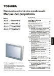
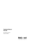
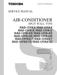
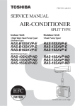
FILE NO. A00-0001 SUPPLEMENT SERVICE MANUAL AIR-CONDITIONER SPLIT WALL TYPE RAS-18YKH-E / RAS-18YAH-E RAS-18YKH-A / RAS-18YAH-A PRINTED IN THAILAND, Apr.,2000 CONTENTS 1. SPECIFICATIONS ....................................................................................... 3 2. CONSTRUCTION VIEWS............................................................................ 5 3. WIRING DIAGRAM ..................................................................................... 7 4. SPECIFICATIONS OF ELECTRICAL PARTS ............................................ 8 5. REFRIGERANT CYCLE DIAGRAM ............................................................ 9 6. CONTROL BLOCK DIAGRAM ................................................................. 10 7. OPERATION DESCRIPTION .................................................................... 12 8. INSTALLATION PROCEDURE ................................................................. 16 9. TROUBLESHOOTING CHART ................................................................. 20 10. EXPLODED VIEWS AND PARTS LIST .................................................... 37 –2– 1. SPECIFICATIONS Model Item Capacity *1 Power source Power consumption Power factor Running current Indoor Outdoor Starting current Moisture removal Noise Refrigerant Indoor (H/M/L) Outdoor Name of refrigerant Rated volume (kW) Phase (V) (Hz) (kW) (%) (A) (A) (A) (lit/h) (dB) (dB) (kg) Refrigerant control Gas side size (mm) Connection type Liquid side size (mm) Connection type Interconnection pipe Maximum length (of one way) *2 (m) Maximum height difference Indoor unit ↑ (m) Outdoor unit ↓ Codensate drain pipe Outer diameter (mm) INDOOR UNIT Height (mm) Dimension Width (mm) Depth (mm) Net weight (kg) Evaporator type Indoor fan type High fan (m³/h) Air volume Medium fan (m³/h) Low fan (m³/h) Fan motor output (W) Air filter OUTDOOR UNIT Height (mm) Dimension Width (mm) Depth (mm) Net weight (kg) Condenser type Outdoor fan type Airflow volume 6 16 RAS-18YKH-E / RAS-18YKH-A 298 1050 180 12 Finned tube Cross flow fan 750 650 550 31 Polypropylene net filter (Washable) RAS-18YAH-E RAS-18YAH-A 690 880 310 65 Finned tube Propeller 220V 240V 240V 3380 3560 3560 65 PH280X3-4MS 2000 Fuse, overload relay Yes 11 to 43 –10 to 21 11 to 43 –10 to 21 (m³/h) Fan motor output Compressor RAS-18YKH-E, RAS-18YAH-E RAS-18YKH-A, RAS-18YAH-A Cooling Heating Cooling Heating 220–240V 240V 5,0 6,35–6,50 5,0 6,50 Single 220–240V 240V 50 2,03–2,20 2,33–2,52 2,20 2,52 91–81 92–85 81 85 0,28–0,30 0,28–0,30 0,30 0,30 9,82–11,00 11,22–12,10 11,00 12,10 60 2,0 44/41/38 54–56 55–57 56 57 R-22 1,45 Capillary tube 12,7 Flare connection 6,35 Flare connection 15 (W) Model Output Safety device Auto louver Usable outdoor temperature range (W) (°C) Specifications are subject to change without notice. –3– * Note : 1 • Capacity is based on the following temperature conditions. JIS C9612-1994 Condition Cooling Heating (DB) 27°C 20°C (WB) 19°C — (DB) 35°C 7°C (WB) 24°C 6°C Temperature Indoor unit inlet air temperature Outdoor unit inlet air temperature * Notes : 2 CHARGELESS • No additional refrigerant required. • This air conditioner accepts a connection piping length of up to 15m and a head of up to 6m. • There is no need to add the refrigerant as long as the total length of the connection piping is up to 15m. –4– 2. CONSTRUCTION VIEWS 2-1. Indoor Unit RAS-18YKH-E, RAS-18YKH-A Indoor heat exchanger Deodorizing filter Dust collecting filter Air filter Air inlet 1050 298 180 Air outlet Power cord (1,7m) Front panel Rear plate 261 264 274 Hanger 136 Wireless remote control 1040 251 55 16 112.8 Remote control holder 59.6 Drain hose 0,60m Hanger Auxiliary pipe (0,49m) Flare Ø6,35 Auxiliary pipe (0,39m) Flare Ø12,7 Detail of installing dimensions of the indoor unit 30 990 44 or more 20 40 450 Minimum distance from ceiling Minimum distance from wall 10 40 123 Anchor bolt hole Ø8 ~ Ø10 Anchor bolt hole Ø6 Minimum distance from wall 130 or more 402 402 123 47 248 Hanger 30 264 80 or more 30 298 15 274 1050 Ø65 Piping hole Center line Installation plate –5– Ø65 Piping hole 5 2-2. Outdoor Unit RAS-18YAH-E, RAS-18YAH-A A Ø25 Drain outlet 340 63,8 68 52 120 140 600 4–Ø12 x 18 hole (for Ø8–Ø10 anchor bolt) 310 23 690 Electric Parts cover Handle Liquid side (Flare Ø6,35) Gas side (Flare Ø15,88) 88 Service port 880 74 340 (pitch) 364 12 12 Handle A Mounting dimension of anchor bolt Detail Drawing 600 600 or more Air inlet 100 or more Air outlet 27 50 Air inlet 340 340 100 or more 600 Ø12 x 18 hole 600 or more 4 x Ø12 x 18 for Ø8–Ø10 anchor bolt –6– 3. WIRING DIAGRAM WHI BRW BRW BRW BRW BRW BRW BRW BRW 1 2 3 4 5 6 7 8 9 1 2 3 4 5 6 7 8 9 WHI BLU BLU CN25 1 2 3 1 2 3 CN15 1 2 3 4 5 6 7 8 9 1 2 3 4 5 6 7 8 9 CN24 F01 Fuse C28 T5A 250V COLOR IDENTIFICATION 3 3 1 1 CN05 1 2 1 2 1 2 3 PJ18 1 2 3 3 BLK RED WHI T01 3 3 1 2 CN30 Transformer BLU 1 2 YEL RED 3 WHI BLK GRN & YEL GRN & YEL Chassis BLK BLK BLK RED WHI RED GRY 1 1 2 CN06 3 3 MAIN P.C. BOARD (MCC-1275) Discharge temperature sensor (TD) 1 1 1 1 BLK CN11 2 3 3 BLK CN05 3 3 DSA TNR R74 1 1 Heat exchanger sensor (TE) 3 3 5 5 T5A, 250V AC 1 1 BLK CN11 2 3 3 BLK TNR R73 CN01 7 7 9 9 1 1 RED Magnetic relay Fuse 3A BLK 22 WHI Buzzer parts Infrared rays receive parts Thermal fuse Thetmo. Heat exchanger 77˚C sensor sensor Ferrite core 21 YEL GRY BRW WHI BLU CN04 1 2 1 2 BLK BLK RED CN26 1 2 1 2 BLK BLK RED WHI BLK CN17 1 2 3 1 2 3 ORN ORN CN03 1 3 5 1 3 5 GRN & BLK WHI YEL 1 2 IC Transformer 1 1 2 RED 1 1 3 3 1 1 CN12 CN33 CN32 MCC-629 GRY 3 3 CN01 2 BLU 1 1 CN22 1 2 1 2 MAIN P.C. BOARD (MCC-1293) N Fuse 3A CN07 TH01 PTH Power supply 18YAH-E : 220–240V ~, 50Hz 18YAH-A : 240V ~, 50Hz 1 1 2 2 L01 Filter 3 3 Outdoor terminal block Crank case heater 6 5 4 3 2 1 6 5 4 3 2 1 CN10 CN13 1 1 2 2 CR01 TNR R98 C26 Running 3 3 TRIAC D04 capacity 5 5 C27 Indoor terminal block RED Fan motor TNR R106 Grand terminal L Thermal fuse 164˚C BLU PNK YEL ORN RED BRW CN16 1 2 3 BRW : BROWN RED : RED WHI : WHITE YEL : YELLOW BLU : BLUE BLK : BLACK GRY : GRAY PNK : PINK ORN : ORANGE GRN & YEL : GREEN & ORANGE Louver motor Indication parts Switch parts 5L3 6T3 3L2 4T2 3 3 1L1 2T1 A1 52C A2 BLK BLU YEL Capacitor Capacitor BLK RED RED WHI PNK BLK Compressor Fan motor CR11 1 1 RY07 CN11 3 3 1 1 BLK 3 3 Coil for 4-way valve 1 1 BLK BLU WHI RED CN04 5 CN02 RY05 TNR R96 CR12 CN03 3 –7– IC07 4. SPECIFICATIONS OF ELECTRICAL PARTS 4-1. Indoor Unit RAS-18YKH-E, RAS-18YKH-A No. Parts name Type Specifications Output (Rated) 31W, 2poles, DC35V, 19W 1 Fan motor (for indoor) AFP-220-31-4B 2 Thermo. sensor (TA-sensor) (microprocessor) 3 Transformer (T01) 4 Microcomputer TMP87CK40AN 5 Heat exchanger sensor (TC-sensor) (microprocessor) 6 Line filter (L01) 7 Diode (DB01) 8 Capacitor (C01) 9 Fuse (F01) 10 Varistor (R98, R106) 11 PTH (TH01) 12 Louver motor TTZ Winding resistance (Ω) (at 20°C) Red-Black White-Black 267,8 147,7 10kΩ at 25°C MCC-629 10kΩ at 25°C 25mH, AC 0,7A KBP06M ECAIEHG222E 220µF, 25V MT3 T5A, 250V 15G431K 430V 82Ω MP35EA7 Output (Rated) 2W, 10poles, 1phase DC12V 4-2. Outdoor Unit RAS-18YAH-E, RAS-18YAH-A No. Parts name Type Specifications Output (Rated) 2000W, 2poles, 1phase, 220–240V, 50Hz 1 Compressor PH280X3-4MS Winding resistance (Ω) (at 20°C) Red-Black White-Black 1,35 2,68 Output (Rated) 65W, 6poles, 1phase, 220–240V, 50Hz 2 Fan motor (for outdoor) MMF-230-65C Winding resistance (Ω) (at 20°C) 3 Running capacitor (for fan motor) SK45FMP AC 450V, 3,5µF 4 Running capacitor (for compressor) SK42CMP45U1 AC 420V, 45µF 5 Solenoid coil (for 4-way valve) 6 Thermo. sensor 7 Case heater 8 Magnetic switch FC2S 3a1b 9 Transformer FT67 220–240V 10 Microcomputer 11 Varistor (R73, 74, 86) 12 Fuse (F01) LB60012 AC 200/240V TE, TD 10kΩ at 25°C 240V, 28W TMP470840 15G471K 470V MT3 T5A, 250V –8– Red-Black White-Black 71,2 139,0 5. REFRIGERANT CYCLE DIAGRAM INDOOR UNIT A (Note) Maximum pipe length is 15m Maximum pipe head is 6m Indoor heat exchanger T1 Cooling 0,39m (Connecting pipe) Ø12,7 0,49m (Connecting pipe) Ø6,35 Heating Cross flow fan O.D. : 12,7mm O.D. : 6,35mm P Packed valve (Ø12,7) Gas container connection (Reinstall etc.) Cooling Packed valve (Ø6,35) Heating Liquid tank 550cc 4-way valve Heating Compressor PH280X3-4MS Cooling Capillary tube Ø1,2 x 700 Capillary tube Ø1,7 x 600 Accumulator Outdoor heat exchanger Refrigerant R-22 1,45kg Propeller fan OUTDOOR UNIT Cooling Heating Surface temp. of heat exchanger interchanging pipe T1 (°C) 18YKH-E, A Fan speed (indoor) 21,0 53,0 20,5 to 25,5 Low temperature Ambient temp. conditions DB/WB (°C) Indoor Outdoor High 20/– 7/6 52,0 to 61,0 Low 27/– 21/15 17,0 45,0 High 20/– –10/–10 Standard 3,0 9,0 High 27/19 35/24 High temperature 3,5 11,0 High 32/23 43/26 Low temperature 2,5 1,5 Low 21/15 21/15 Standard Cooling ) means check points of Gas Leak Standard pressure P (kg/cm²G) 18YAH-E, A 50Hz Heating Mark ( * High temperature 1 Note : • Measure the heat exchanger temperature at the center of U-bend. (By means of TC sensor.) *1 • During heating overload, the high temperature limit control operation is included. –9– Functions Heat Exchanger Sensor • 3-minute Delay at Restart for Compressor Infrared Rays Signal Receiver Operation (START/STOP) Initializing Circuit Clock Frequency Oscillator Circuit • Motor Revolution Control ECONO. Sign Display • Processing (Temperature Processing) 8MHz PRE DEF. Sign Display • Timer – 10 – Operation Mode Selection AUTO, COOL, DRY, FAN ONLY Thermo. Setting Timer Display • Serial Signal Communication Power Supply Circuit Fan Speed Selection ON TIMER Setting Indoor Fan Motor Photo Triac Louver ON/OFF Signal OFF TIMER Setting Noise Filter Louver AUTO Swing Louver Driver Louver Motor Louver Direction Setting Serial Signal Transmitter/Receiver ECONO. From Outdoor Unit Transformer Serial Signal Communication (outdoor unit) 6. CONTROL BLOCK DIAGRAM Infrared Rays CLOCK FREQUENCY 36,864kHz Remote Control Operation Display • Louver Control Temperature Sensor 6-1. Indoor Unit M.C.U Indoor Unit Control Panel 6-2. Outdoor Unit C.P.U TD Discharge Temperature Sensor 4-Way Valve ON/OFF Signal Relay RY05 4-Way Valve Relay RY07 Magnetic Switch Triac Outdoor Fan Motor Relay Driver TE Heat Exchanger Sensor Compressor ON/OFF Signal Outdoor Fan ON/OFF Signal Photo Coupler – 11 – Initializing Circuit Serial Signal Communication (Indoor Unit) Serial Signal Transmitter/ Receiver • • • • • Compressor Control 4-Way Valve Control Outdoor Fan Control Defrost Operation Serial Signal Communication Power Supply (for Indoor Unit) Clock frequency Oscillator Circuit 6MHz Power Supply Circuit Transformer RAS-18YAH-E : AC220–240V, 50Hz RAS-18YAH-A : AC240V, 50Hz Compressor 7. OPERATION DESCRIPTION 7-2. COOL Operation (MODE of the remote control : FAN ONLY) ON HIGH 27 MED 26 Fig. 7-2-1 LOW(+) 25 LOW 24 Outdoor fan (Room temp. – Set temp.) OFF ON OFF OFF ON Set 0 temp. 28 ON +1 OPERATION display Room temp. 2) When the FAN is set to LOW, MED, or HIGH, the indoor fan motor operates with a constant in volume as listed in Table 7-1-1. 4-way valve 1) When the FAN is set to AUTO, the indoor fan motor operates as shown in Fig 7-1-1. (MODE of the remote control : COOL) (1) Compressor, 4-way valve, outdoor fan and operation display are controlled as shown in Fig. 7-2-1. Common relay (1) Fan speed setting Compressor 7-1. FAN ONLY Operation (2) A cool operation is carried out when the indoor microcomputer sends the operation signal to the outdoor microcomputer. LOW 1) When the FAN is set to AUTO, the indoor fan motor operates as shown in Fig 7-2-2. Fig. 7-1-1 Auto setting of air volume 2) When the FAN is set to LOW, MED, or HIGH, the indoor fan motor operates with a constant in volume as listed in Table 7-1-1. Table 7-1-1 Manual setting of FAN SPEED HIGH Air volume (m3/h) LOW 550 MED 650 HIGH 750 (2) Once the setting is made, the operation mode is memorized in the microcomputer so that the same operation can be effected thereafter simply by pushing the START/STOP button. FAN (Room temp. – Set temp.) Indication of FAN SPEED AUTO Manual HIGH +1,5 MED (+) +1,0 MED +0,5 According to the set position LOW (+) +0 LOW Set –0,5 temp. RY01 OFF Fig. 7-2-2 (3) Once the setting is made, the operation mode is memorized in the microcomputer so that the same operation can be effected thereafter simply by pushing the START/STOP button. 7-2-1. Louver Control (1) By pushing the SET button of the remote control during the operation, the louver can be set to the desired position. And the louver position is stored in the microcomputer, the louvers will be set to the position automatically at the next operation. (2) When the AUTO button is pushed, the louver vertically swings within range of 25deg. – 12 – 7-3-1. Louver Control 7-3. HEAT Operation (MODE of the remote control : HEAT) (1) By pushing the SET button of the remote control during the operation, the louver can be set to the desired position. (2) When the AUTO button is pushed, the louver vertically swings within range of 25deg. And the louver position is stored in the microcomputer, and at the next operation, the louvers will be set to the stored position automatically at the next operation. 0 OFF ON ON OFF ON 7-3-2. Cool Airflow Control (1) If the indoor heat-exchanger temperature detected by the indoor heat-exchanger sensor is 16°C or below, the indoor fan stops and if the temperature rises to 26°C or above, the fan is restarted. –1 Outdoor fan OPERATION display 4-way valve ON Common relay ON Compressor (Room temp. – Set temp.) (1) Compressor, 4-way valve, outdoor fan and operation display are controlled as shown in Fig. 7-3-1. Details are in 7-8. Fig. 7-3-1 (2) A heat operation is carried out when the indoor microcomputer sends the operation signal to the outdoor microcomputer. The indoor fan motor operates as shown in Fig. 7-3-2, when the FAN is set to AUTO. The motor operates with a constant air volume as listed in Table 7-1-1, when the FAN is set to LOW, MED, or HIGH. RY01 OFF FAN AUTO (Room temp. – Set temp.) Set 10,5 temp. 0 Manual LOW LOW (+) –0,5 MED –1,0 MED (+) According to the set position –1,5 HIGH Fig. 7-3-2 (3) Once the setting is made, the operation mode is memorized in the microcomputer so that the same operation can be effected thereafter simply by pushing the START/STOP button. – 13 – 7-4-1. Temporary Auto 7-4. AUTO Operation (MODE of the remote control : AUTO) When the TEMPORARY button is pushed, the set temperature is fixed at 24°C and controlled in accordance with the chart shown in Fig. 7-4-1. (Room temp. – Set temp.) (1) One of the 3 modes, Cooling, Fan only and Heating is selected according to room temperature at which operation is to start, as shown in Fig. 7-4-1. The Fan mode will continue until room temperature reaches a level at which another mode is selected. +3 Cooling mode (The same cooling mode as the room temperature control is set at set temp. –3˚C) –3 Heating mode (The same heating mode as the room temperature control is set at set temp. +3˚C) Fig. 7-4-1 7-5. ECONO. Mode 7-5-2. Heating When the ECONO. button is pushed, during COOL, HEAT and AUTO operation, the OPERATION display is turned off and the ECONO. display is lit and the indoor unit operates quietly and mildly with controlling airflow. (1) In the ECONO. mode, the set temp. by the remote control is changed automatically as shown in Fig. 7-5-2. (2) Fan speed → LOW ECONO. button is pushed 7-5-1. Cooling (1) In the ECONO. mode, the set temp. by the remote control is changed automatically as shown in Fig. 7-5-1. 0H 1H 2H Set temp. (2) Fan speed → LOW -1 (˚C) Set temp. is changed Set temp. is changed -2 Set temp. is changed +2 Set temp. is changed (˚C) +1 Fig. 7-5-2 Set temp. 0H 1H 2H TIME ECONO. button is pushed Fig. 7-5-1 – 14 – TIME 7-6. High-Temperature Limit Control (Heating Operation) 7-8. Cool Airflow Prevention Control (Heating Operation) The microprocessor detects the indoor heat exchanger temperature so as to prevent exceeding the condensate pressure. (1) During the heating operation, the indoor fan speed is controlled automatically in accordance with the indoor heat exchanger temperature to prevent blowing the cool air. Control is performed as shown in Fig. 7-6-1. Control is performed as shown in Fig. 7-8-1. Heat exchanger temperature Heat exchanger temperature (˚C) 60 Compressor, Outdoor fan (˚C) 30 *1 54 Indoor fan speed 26 OFF According to the set position 20 52 L (Low) 16 ON OFF *1 ····· Only outdoor fan is turned off. Fig. 7-8-1 Fig. 7-6-1 7-7. Low-Temperature Limit Control (Cooling Operation) The microprocessor detects the indoor heat exchanger temperature so as to prevent freezing up the indoor heat exchanger. Control is performed as shown in Fig. 7-7-1. Heat exchanger temperature (˚C) 12 2 Compressor Outdoor fan ON Less than 2˚C continues for 6 minutes OFF (2) As soon as the defrost operation starts, the indoor fan stops. 7-9. Defrost Operation During heat operation, if the temperature (Evaporating temperature) detected by the outdoor heat exchange sensor (TE :Defrost) lowers by the set degree less than the temperature detected at start time, the operation enters the defrost operation. In this time, the 4-way valve relay and the outdoor fan are turned off. The indoor fan is turned off by the cool air blow-out preventing control of the indoor microcomputer at the indoor side, and "PRE.-DEF." on the remote control goes on. The defrost operation is automatically reset to the normal operation when the temperature detected by the above-mentioned TE sensor rises up to the set value, or when Max. 12 minutes of the operation time has passed. Fig. 7-7-1 – 15 – 8. INSTALLATION PROCEDURE 8-2. Installation Diagram of Indoor and Outdoor Units 8-1. Safety Cautions Anchor bolt arrangement of outdoor unit Power supply cord of parts of appliance for outdoor use shall be more than polychloroprene sheathed flexible cord (design H05 RN-F), or cord designation 245 IEC 57. To Disconnect the Appliance from the Mains Supply. This appliance must be connected to the mains by means of a circuit breaker or a switch with a contact separation of at least 3 mm. If this is not possible, a power supply plug with earth must be used. This plug must be easily accessible after installation. The plug must be disconnected from the power supply socket in order to disconnect the appliance completely from the mains. REQUIREMENT OF REPORT TO THE LOCAL POWER SUPPLIER Please make sure certainly that the installation of this air conditioner will be reported to the local power supplier before installation. If you have any obscure problems (or if the power supplier does not accept the installation) of this appliance, service agency will take adequate countermeasures. Mounting 6 screw 80m 340 mm 64 mm CAUTION Clip anchor (local part) 600 mm Air intlet 120 mm Air outlet During piping installation 44mm or more For general public use 1 Installation plate Wall mo r mo re Insert the remote control holder cushion between the indoor unit and wall, and lift the indoor unit to make work easier. Drain outlet • Secure the outdoor unit with the anchor bolts if the unit is likely to be exposed to a strong wind. • Use Ø8 or Ø10 anchor bolts. • If it is necessary to drain the defrost water from the outdoor unit, base pan attach the 9 drain nipple to the outdoor unit before installing it. The drain outlet is located as shown above. Do not allow the drain hose to get slack. 130 or mmm ore Cut the piping hole sloped slightly Air filters (for both sides) Make sure to run the drain hose sloped downward. 4 Pan head wood screws The auxiliary piping can be connected to the left, rear or down. DANGER 7 Deodorizing filter 8 Purifying filter 3 Remote control holder Left Down Rear left Before installing the wireless remote control 5 Batteries • With the remote control cover opened, load the supplied batteries correctly, observing their polarity. Saddle Cover CAUTION 8-2-1. Optional Installation Parts Parts name A B Pipe insulating material (Polyethylene foam, 6mm thick) C Putty, PVC tapes Extention drain hose (Option : RB-821SW) re r mo Refrigerant piping Liquid : Ø6,35 Gas side : Ø12,7 o or m Electric parts cover o mm 600 Part code 6 mm thick heat resisting polyethylene foam re mm 100 Drainage 9 100 or mmm ore • Never modify this unit by removing any of the safety guards or by by-passing any of the safety interlock switches. • Do not install in a place which cannot bear the weight of the unit. Personal injury and property damage can result if the unit falls. • Before doing the electrical work, attach an approved plug to the power supply cord. And make sure the equipment to be earthed. • Appliance shall be installed in accordance with national wiring regulations. Insulation of refrigerant pipes insulates the pipes separately, not together. Vinyl tape Apply after carrying out a drainage test. Wireless remote control 2 WARNING • Exposure of unit to water or other moisture before installation will result in an electrical short. Do not store in a wet basement or expose to rain or water. • After unpacking the unit, examine it carefully for possible damage. If you detect any damage, do not install the unit. Contact your Toshiba dealer immediately. • Do not install in a place that can increase the vibration of the unit. Do not install in a place that can amplify the noise level of the unit or where noise and discharged air might disturb user’s neighbors. • To avoid personal injury, be careful when handling parts with sharp edges. • Please read the installation manual carefully before installing the unit. It contains further important instructions for proper installation. Rear 2 Wireless remote control 600mm or more – 16 – • FOR USE BY QUALIFIED PERSONS ONLY. • TURN OFF MAIN POWER SUPPLY BEFORE ATTEMPTING ANY ELECTRICAL WORK. MAKE SURE ALL POWER SWITCHES ARE OFF. FAILURE TO DO SO MAY CAUSE ELECTRIC SHOCK. • CONNECT THE CONNECTING CABLE CORRECTLY. IF THE CONNECTING CABLE IS CONNECTED BY WRONG WAY, ELECTRIC PARTS MAY BE DAMAGED. • CHECK THE EARTH WIRE IS NOT BROKEN OR DISCONNECTED BEFORE INSTALLATION. • DO NOT INSTALL NEAR CONCENTRATIONS OF COMBUSTIBLE GAS OR GAS VAPORS. FAILURE TO FOLLOW THIS INSTRUCTION CAN RESULT IN FIRE OR EXPLOSION. • TO PREVENT OVERHEATING THE INDOOR UNIT AND CAUSING A FIRE HAZARD, PLACE THE UNIT WELL AWAY (MORE THAN 2M.) FROM HEAT SOURCES SUCH AS RADIATORS, HEAT REGISTORS, FURNACE, STOVES, ETC. Q’ty Each one 1 Each one 600 or mmm ore Drain nipple Ø25 Separately sold or market available drain hose. Bottom plate • Install the provided drain nipple in the hole of the bottom plate of the outdoor unit. (See figure at left.) • Perform proper drainage processing using a separately sold or market available drain hose. (16 mm inner diameter.) • Do not use an ordinary hose available at the market, since it tend to get flat, resulting in a clog of drain water. Loop the connective cable (about 100 mm in diameter and 300 – 350 mm long). 8-3. Indoor Unit 8-3-3. Cutting a Hole and Mounting Installation Plate 8-3-1. Installation Place • A place which provides the spaces around the indoor unit as shown in the above diagram. • A place where there is no obstacle near the air inlet and outlet. • A place which allows an easy installation of the piping to the outdoor unit. • A place which allows the front panel to be opened. CAUTION Remote control (Top view) Indoor unit 100mm 47mm Center of pipe hole is located on the line indicated by the arrow and 100 mm apart from the pipe hole center line. Indoor unit outline 45 ˚ ˚ 45˚ Reception Remote control range Reception range Remote control * : Axial distance Fig. 8-3-1 8-3-2. Installation Parts Part with an asterisk ( ) is packaged with outdoor unit. * Name of parts (Q'ty) 1 Part No. When installing the refrigerant pipes from the rear. Determine the pipe hole position using the installation plate, and drill the pipe hole Ø65 mm slightly downward. NOTE When using the drill to pierce the wall that contains a metal lath, wire lath or metal plate, be sure to use a pipe hole brim ring sold separately. For installation of the indoor unit, use the paper pattern on the back. Name of parts (Q'ty) 450mm n plate llatio 1 Insta 44mm or more it Indoore un outlin 40mm 21mm 4mm m 130m or more 80mm or more bolt hole Anchor 40mm 100mm Thread e hole rant pip Refrige Ø65mm 100mm Weight 47mm rant Refrige le pipe ho Ø65mm Fig. 8-3-3 When the installation plate is directly mounted on the wall 1. Securely fit the installation plate onto the wall by screwing it in the upper and lower parts to hook up the indoor unit. 2. To mount the installation Installation plate plate on a concrete wall with (Keep horizontal direction) anchor bolts, utilize the anchor bolt holes as illustrated in the above figure. 3. Install the installation plate Fig. 8-3-4 horizontally in the wall. 6 Mounting screw Ø4x 25 x 8 Installation plate x 1 Failure to firmly install the unit may result in personal injury and property damage if the unit falls. 7 2 Deodorizing filter x 1 Wireless remote control x 1 3 8 Remote control holder x 1 4 Purifying filter x 1 9 Pan head wood screw Ø3,1 x 16 x 2 Drain nipple *x1 Name Others 5 Batteries x 2 CAUTION Owner’s manual Installation manual 1. Adjust the lateral position of the installation plate without changing the height, so that each screw hole in the plate comes in the center of a pillar or stud. 2. Make pilot holes with a bit to prevent the studs from cracking, and then drive the screws into the holes and tighten. CAUTION When installing the installation plate with mounting screw, do not use the anchor bolt hole. Otherwise the unit may fall down and result in personal injury and property damage. Installation plate Hole in anchor Bolt Installation Concrete wall plate Mounting the installation plate CAUTION • Be sure to refer the wiring system diagram labeled inside the side panel. • Check local electrical codes and also any specific wiring instruction or limitation. How to remove the front panel (6) (6) (7) • There may be a wire conduit embedded in the wall. Confirm on the blue prints or ask the builder. • Install the installation plate using 4 to 8 pieces of mounting screw securing four corners with screws. • Make sure of the proper installation of the installation plate before mounting the indoor unit. Hole in anchor 5m * 7m 7m 5m (Side view) 75 – 17 – • A place where there are no obstacles such as a curtain that may block the signal from the indoor unit. • Do not install the remote control in a place exposed to direct sunlight or close to a heating source, such as a stove. • Keep the remote control at least 1 m apart from the nearest TV set or stereo equipment. (This is necessary to prevent image disturbances or noise interference.) • The location of the remote control should be determined as shown below. Indoor unit Refrigerant pipe hole Ø65mm Hooking section Fig. 8-3-2 • Direct sunlight to the indoor unit wireless receiver should be avoided. • The microprocessor in the indoor unit should not be too close to r-f noise sources. (For details, see the owner's manual.) Part No. Cutting a hole • In the case of a reinforced concrete wall (1) In the selected area on the reinforced concrete wall, bore holes at intervals of 450 mm, and drive clip anchors or hole in anchors into them. Anchor bolt (2) Attach the installation plate to the wall by screwing bolts or nuts into the anchors. Projection 15mm However, in the case where hole in or less anchors are used, the depth of the holes should be adjusted so that the nutheads extend no more than 15 mm. Fig. 8-3-5 Nut with threaded hole 8 mm dia. Less than 15 mm Concrete wall Fig. 8-3-6 • In the case of the pipe on the back Using the pattern, position the pipe hole, and bore the hole slightly downward. 8-3-4. Electrical Work Important items of indoor unit wiring 1. For electrical works the wiring and cables must be performed in compliance with national wiring standard or regulation. If incorrect and incomplete wiring is carried out, it will cause an electrical fire or electrical shock. 2. Do not use the inter-connecting cable. Never execute the connection of electrical wiring with other method than the approved one. (exp. use the terminal block etc.) 3. Prepare the interior power supply cord capacity sufficient for starting and usage current of air conditioner. 4. Connect the connecting cable to the terminal as identified with their respective matched numbers on the terminal block of outdoor unit. 5. Fix the cable securely with the cord clamps to the specified position. 6. Do not damage or scratch the conductive core & inner insulator of power supply and inter connecting cables when peeling them. 7. Do not deform or smash the surface of the cables. Do not press or fix the cord and cables firmly with staples, etc. (3) (4) (5) (3) (4) (1) (2) (1) (2) (1) (2) Screw caps and screws Fig. 8-3-8 (1) Open the screw caps and remove three front panel fixing screws. (2) Put the screw caps back as they were. (3) Press the part saying “PUSH” on the air inlet grille to open the air inlet grille. Remove three black front panel fixing screws. (4) Close the air inlet grille. (5) Manually open the vertical air flow louver directly below. (6) Open the front panel lower portion until it comes in contact with the vertical air flow louver. Lift up the front panel upper portion in a forward diagonal direction to unhook the clicks inside the front panel upper portion. (7) After unhooking the nails inside the main unit upper portion, rotate the front panel upper portion towards you to remove the front panel from the unit body. Front panel Rear plate Electrical component box cover Screws Cord clamp Rear plate bushing Wiring cover Screw Fig. 8-3-9 Stripping length of connecting cable 220 mm 10 mm 3 2 1 How to connect the cable 1. Remove the side panel. (2 screws) 2. Remove the electric parts cover and cord clamp. 3. Insert the connecting cable fully into the terminal block and secure it by screw tightly. Tightening torque : 1,2 N•m (0,12 kgf•m) 4. Secure the connecting cable with How to open the screw cap • Place your finger on the the cord clamp. lower part and push up to 5. Fix the electric open the screw cap. parts cover and side panel. Fig. 8-3-7 Screws (7) 50 mm 60 mm Fig. 8-3-10 NOTE • Use standard wire only • Wire type : More than H05 RN-F (1,3 mm² or more) • Insert the connecting cable fully into the terminal block and secure it by screw tightly. • Tightening torque : 1,2 N•m (12 kgf•cm) • Secure the connecting cable with the cord clamp. • Fix the wiring cover, rear plate bushing and front panel on the indoor unit. Underside connection with piping 1. Cut out the knock-out piece from the right below of the rear plate with a knife, etc. Smooth the cut edges. TEMPORARY Slit part REMOTE CONTROL AUTO TEST RUN (COOL) 8-3-7. Drainage 8-3-9. Check and Test Operation 1. Run the drain hose sloping downwards. ¨ NOTE • Hole should be made at a slight downward slant to the outdoor side. Do not rise the drain hose. Pipe holder Do not form the drain hose into the waved shape. ¨ 50 mm or more Pipe holder Cord clamp Screws 2 Terminal block 1 Grounding wire Connecting cable Fig. 8-3-14 Do not put the drain hose end into water. Indoor unit Wiring cover Screw Auxiliary pipes 8-3-5. Piping and Drain Hose Installation Left-hand connection with piping • After scribing slits of the rear panel by a knife or a markingoff pin, cut them by a pair of nippers or the like. – 18 – Slit (rear panel) Fig. 8-3-12 Bend the connecting pipe so that it is laid within 52 mm above the wall surface. If the connecting pipe is laid exceeding 52 mm above the wall surface, the indoor unit may unstably be set on the wall. When bending the connecting pipe, make sure to use spring bender so as not to crush the pipe. Bend the connecting pipe within a radius of 40 mm. NOTE If the pipe is bent incorrectly, the indoor unit would be unstably set on the wall and the air conditioner might be raised. 1. When the piping runs to the left, remove the left side body bushing of the rear panel. You may need the body bushing when you relocate the unit, so be sure to make customer keep it in a safe place. 2. After passing the connecting pipe through the pipe hole, connect the connecting pipe to the auxiliary pipes and wrap facing tape around them. 52 mm Outward form of indoor unit R 40mm (Use polisin (polyethylene core) or the like for bending pipe.) 80 ˚ Use the handle of screwdriver,etc. Fig. 8-3-13 Do not put the drain hose end in the drainage ditch. Fig. 8-3-18 • Bind the auxiliary pipes (two) and connecting cable with facing tape tightly. In case of leftward piping and rear-leftward piping, bind the auxiliary pipes (two) only with facing tape. Fig. 8-3-11 ¨ ¨ ¨ ¨ Rear plate CAUTION Connecting cable 2. Put water in the drain pan and make sure that the water is drained out of doors. 3. When connecting extension drain hose, insulate the connecting part of extension drain hose with shield pipe. Shield pipe Drain hose Inside the room Installation plate ¨ 1. Check the unit is firmly hooked up on the installation plate. 2. Check the connecting pipes tightened securely. Confirm that there is no gas leakage. 3. Confirm that all connecting cables are secured and correct. 4. Check the pipe insulation. 5. Check the drainage. 6. Connection of the grounding wire. 7. To switch the TEST RUN (COOL) mode, turn the switch on. Extension drain hose Fig. 8-3-19 TEMPORARY Fig. 8-3-15 • Carefully arrange pipes so that any pipe does not stick out of the rear plate of the indoor unit. • Carefully connect the auxiliary pipes and connecting pipes to each other and cut off the insulating tape wound on the connecting pipe to avoid double-taping at the joint, moreover, seal the joint with the vinyl tape, etc. • Since dewing results in a machine trouble, make sure to insulate both the connecting pipes. (Use polyethylene foam as insulating material.) • When bending a pipe, carefully do it not to crush it. 8-3-6. Indoor Unit Fixing 1. Pass the pipe through the hole in the wall, and hook the indoor unit on the installation plate at the upper hooks. 2. Swing the indoor unit to right and left to confirm that it is firmly hooked up on the installation plate. 3. While pushing the indoor unit onto the wall by the lower part, hook it up on the installation plate by the lower part. Hook here Pull the indoor unit 1 toward you by the 1 Installation plate lower part to confirm 2 Hook here that it is firmly hooked up on the installation plate. This air conditioner has the structure designed to drain water collected from dew, which forms on the back of the indoor unit, to the drain pan. Therefore, do not store the power cord and other parts at a height above the drain guide. Fig. 8-3-16 CAUTION TEST RUN (COOL) Arrange the drain pipe for proper drainage from the unit. Improper drainage can result in dew-dropping. How to install the front panel on the indoor unit Install the front panel through the opposite order of “How to remove the front panel”. When the panel is removed and mounted again, take the following action : After fastening the 6 screws, be sure to hook the inside clicks , , and of the front panel shown in the diagram, right gap is between the front panel and the rear plate. • If cooling (dry) operation is made without pushing the air outlet, dew can be deposited on the front panel surface. In addition, a gap between the front panel and the body will become wider, spoiling the appearance. Push Push Push 3 1 2 Fig. 8-3-22 Make sure to return the TEMPORARY switch to REMOTE CONTROL. Three-minutes protection feature A protection feature prevents the air conditioner from being active for about 3 minuets when it is restarted immediately after operation. ¨ Fig. 8-3-20 • Check the flare nut connections, valve stem cap connections and service Electric parts cap connections for gas cover D leak with a leak detector or soap water. Wall Flare nut connections (Outdoor unit) Drain guide Space for pipes Fig. 8-3-21 8. Operate the unit at cooling operation mode for fifteen minutes or more. Measure the temperature of the intake and discharge air. Ensure the difference between the intake temperature and the discharge one is more than 8°C. NOTE: Three-minutes protection feature 8-3-8. Gas Leak Test C Flare nut connections (indoor unit) Fig. 8-3-17 REMOTE CONTROL AUTO Valve stem cap connection A Service cap connection B Valve stem cap connection ¨ A protection feature prevents the air conditioner from being activated for about 3 minutes when it is restarted immediately after operation. 9. Check the remote control operation when it is at fixed position. When finished the check and test operation, make sure to return the TEMPORARY switch to REMOTE CONTROL. ¨ 10. Explain to the customer on the correct usage of air conditioner with simple layman’s terms. 8-4. Outdoor Unit 8-4-1. Installation Place • A place which provides the spaces around the outdoor unit as required above in the diagram. • A dry sunny place. If the place is exposed to direct sunlight use an awning for protection. • A place which can bear the weight of the outdoor unit and does not allow an increase in noise level and vibration. • A place where the operation noise and discharged air do not disturb your neighbors. • A place which is not exposed to a strong wind. • A place free of a leakage of combustible gases. • A place which does not block a passage. • When the outdoor unit is to be installed in an elevated position, be sure to secure its feet. • A place where the drain water does not raise any problem. • An allowable length of the refrigerant piping is up to 15 m. • An allowable heat level is up to 6 m. Outer dia. (mm) 6,35 12,7 Tightening torque 16 (1,6 kgf•m) 49 (5,0 kgf•m) Half union Internally threaded side Use a wrench to secure. Fig. 8-4-4 Roughness Outer dia. (mm) 6,35 12,7 A (mm) Thickness (mm) Imperial Rigid 1,3 0,7 0,8 1,8 1,0 to 1,1 1,0 A D B1 Tightening Connection Packed valve Charge hose (B) Charge hose (A) VP Liquid (Ø6,35) Fig. 8-4-5 • KEEP IMPORTANT 4 POINTS FOR PIPING WORK (1)Take away dust and moisture (Inside of the connecting pipes.) (2)Tight connection (between pipes and unit) (3)Evacuate the air in the connecting pipes using VACUUM PUMP. (4)Check gas leak (connected points) Packed Valve Handling Precautions Fig. 8-4-3 Align the centers of the connecting pipes and tighten the flare nut as far as possible with your fingers Then tighten the nut with a spanner and torque wrench as shown in the figure. • Open the valve stem all the way out; so not try to open it beyond the stopper. • Securely tighten the valve stem cap torque is as follows; Gas pipes side (ø12,7 mm) : 49 N•m (5,0 kgf•m) Liquid pipe side (ø6,35 mm) : 16 N•m (1,6 kgf•m) Hexagon wrench is required. Flare nut Stopper CAUTION • Do not apply excess torque. Otherwise, the nut may crack depending on the conditions. Screw Cord clamp Valve body Valve stem Valve stem cap Cord clamp Power supply cord Connecting cable Fig. 8-4-7 Stripping length of power cord 90mm Earth line 10mm N L NOTE 10mm 80mm Fig. 8-4-8 • Use standard wire only. • Wire type : 3,5 mm² or more AWG-12. WARNING To plug the cable in the plug receptacle, take the following precaution. THIS APPLIANCE MUST BE EARTHED. IMPORTANT THE WIRES IN THIS MAINS LEAD ARE COLORED IN ACCORDANCE WITH THE FOLLOWING CODE : L : Brown N : Blue : Green and Yellow CAUTION Pipe Earth line RAS-18YAH-E (RAS-18YKH-E) RAS-18YAH-A (RAS-18YKH-A) 50 Hz ~, 220 – 240V 50 Hz ~, 240V Maximum running current 16,8 A Plug socket & fuse rating Wiring 20 A 3,5 mm² (AWG-12) or more CAUTION If incorrect/incomplete wiring is carried out, it will cause an electrical fire or smoke. Prepare the power source for exclusive use with the air conditioner. This product can be connected to the mains. Connection to fixed wiring : A switch or circuit breaker which disconnects all poles and has a contect separation of at least 3 mm must be incorporated in the fixed wiring. An approved short circuit breaker or switches must be used. 8-4-5. Wiring Connection 1. Remove the electric parts cover from the outdoor unit. (4 screws) 2. Connect the connecting cable to the terminal as identified with their respective matched numbers on the terminal block of indoor and outdoor unit. (1,3 mm² AWG-16 or more) 3. When connecting the connecting cable to the outdoor unit terminal, make a loop as shown installation diagram, to prevent water coming in the outdoor unit. 4. Insulate the unused cords (conductors) with strip the sheath of connecting cable to prevent the shortage or electric leakage. Process them so that they do not touch any electrical or metal parts. Stripping length of connecting cable 10mm Terminal block 60mm Earth line 1 3 2 3 Terminal screw Screws 2 1 A Die Screw Use of vacuum pump Service port Fig. 8-4-2 Terminal block 3 Earth line Evacuate the air in the connecting pipes and in the indoor unit using vacuum pump. Do not use the refrigerant in the outdoor unit. For details, see the manual of vacuum pump. Gas (Ø12,7) 2. Insert a flare nut into the pipe, and flare the pipe. 1 2 AIR PURGE C Warp Terminal block L N Indoor unit 1. Cut the pipe with a pipe cutter. Model Power source For the air conditioner that has no power cord, connect a power cord to it as mentioned below. • Remove the electric parts cover from the outdoor unit. (4 screws) • After removing the electric parts cover, remove the cord clamp. • Connect and secure the power supply cord. 8-4-3. Evacuating 8-4-2. Refrigerant Piping Connection Obliquity Use a torque wrench to tighten. 5m m – 19 – 1. Install the outdoor unit without anything blocking the air discharging. 2. When the outdoor unit is installed in a place exposed always to a strong wind like a coast or on a high story of a building, secure the normal fan operation using a duct or a wind shield. 3. Specially in windy area, install the unit to prevent the admission of wind. 4. Installation in the following places may result trouble. Do not install the unit such places. • A place full of machine oil. • A saline-place such as coast. • A place full of sulfide gas. • A place where high-frequency waves are likely to be generated as from audio equipment, Strong wind welders, and medical Fig. 8-4-1 equipment. 90˚ Flare nut Externally threaded side 8-4-4. Electrical Work How to connect the power cord 1. Connect the charge hose (A) from the manifold valve to the charge inlet of the gas side packed valve. 2. Connect the charge hose (B) to the port of vacuum pump. 3. Open fully the low pressure side handle of the manifold valve. 4. Operate the vacuum pump. 5. Close the low pressure side handle of manifold valve after evacuating and stop the vacuum pump. Continue evacuating more than 15 minutes and check the pressure gage indicates –0,1 MPa (–76 cm Hg). 6. Open the stems of packed Pressure Manifold valve valves A and B1 all the way. gage High pressure 7. Securely tighten the stem Low pressure side side handle handle cap to each of the packed Lo Hi Outdoor unit valve stems. CAUTION Flaring (Unit : N•m) Additional tightening torque 18 (1,8 kgf•m) 54 (5,5 kgf•m) Fig. 8-4-6 -LIVE -NEUTRAL -EARTH L N Fig. 8-4-9 As the colors of the flexible cord of this appliance may not correspond with the colored markings, to identify terminals in your plug, as follows : Connect BROWN colored core to plug terminal marked letter “L”. Connect BLUE colored core to plug terminal marked letter “N”. Connect GREEN and YELLOW colored core to plug terminal marked Earth symbol “ ”. The installation of the cables has to be done in such a way that the basic insulated wires for the infrared sensor can not be touched. Use the power supply cord/cables with thickness, type, and protective devices specified in the installation manual. Prepare the interior power supply cord and cables wiring with current capacity sufficient for starting and usage of air conditioner. 10mm 50mm Connecting cable Fig. 8-4-10 Cord clamp CAUTION 1. Wrong wiring connection may cause some electrical parts burn out. 2. Be sure to use the cord clamps and the electric parts cover to the specified positions with attached to the product. Mount the electrical parts cover for cables of connecting section firmly with the screws. 3. Do not damage or scratch the conductive core and inner insulator of power supply and inter connecting cables when peeling them. 4. Be sure to comply with local cords on running the wire from indoor unit to outdoor unit (size of wire and wiring method etc.) Wire type : More than H05 RN-F 5. Use the power supply cord and inter-connecting cable with specified thickness, specified type, and protective devices specified. 6. No wire should touch refrigerant piping, compressor of any moving parts. 9. TROUBLESHOOTING CHART 9-1-2. Incorrect Cable Connection between Indoor and Outdoor Units Troubleshooting Procedures : • Following details of “What to be pre-checked first”, make sure of the basic items. The indoor unit is connected to the outdoor unit with 4 cables. Make certain that the indoor and outdoor units have been connected properly, with terminals assigned the same numbers wired to each other. If the connectors are not connected as specified, the outdoor unit will not operate normally, or OPERATION lamp and TIMER lamp will flash (5Hz). • When there is no trouble corresponding to above, check in detail the faulty parts following “How to judge faulty parts by symptoms” later. 9-1-3. Misleading but Good Operations (Program Controlled Operation) 9-1. What to be Prechecked First 9-1-1. Power Supply Voltage The line voltage must be AC 220–240V (RAS18YKH-E, RAS-18YAH-E), 240V (RAS-18YKH-A, RAS-18YAH-A). If the line voltage is not within this range, this air conditioner may not work normally. The microcomputer performs the operations listed in Table 9-1-1 to control the air conditioner. If a claim is made on the operation, check whether it corresponds to the contents in the Table 9-1-1. If it does, it is an indispensable operation for the control and maintenance of the air conditioner: it is not a failure of the unit. Table 9-1-1 No. Description Operation of air-conditioner 1 When the breaker is turned on, the OPERATION lamp on the setting indication part flashes. The OPERATION lamp flashes, indicating that power is turned on. If this happens, push the START/STOP button once to cause the lamp to stop flashing. A power outage also causes the lamp to flash. 2 Fan speed remains unchanged in the dry mode. Fan speed is automatically controlled in the dry mode. 3 Room temperature is in the range under which the compressor is turned off, but the compressor will not stop. The compressor will not stop while the compressor on hold timer (3-minutes timer) is actuated. 4 The compressor will not switch on or off even when the thermo control is operated in the dry operation. In the dry mode, the compressor goes on and off at regular intervals, independent of the thermo control. 5 The PRE-DEF. lamp comes on when the heating operation is started. The PRE-DEF. lamp comes on during defrost operation and when the indoor heat exchanger temperature is low when the heating operation is started. At this time, the indoor fan is stopped to prevent cold air from drifting into the room. 6 The outdoor fan stops once in the while during the heating operation. • When the indoor heat exchanger temperature is high, the outdoor fan may be stopped by the high-temperature limit control operation. 7 Compressor does not work though room temperature is in the range of turning the compressor on. Compressor does not work while the compressor restart delay (3-min.) timer is active. The same is true after power is turned on, as the time is still active. 8 During automatic operation, the operation mode changes. After selection of the cooling and heating operation, the operation mode is selected again when the compressor off mode continues for 15 min. according to the room temperature. 9 During automatic operation mode, the fan only operation continues. When the room temperature is within setting temperature ± 1°C the fan only mode is selected. – 20 – 9-2-2. Display of Abnormalities and Judgement of the Abnormal Spots 9-2. Primary Judgment of Trouble Sources The indoor unit of this machine observes the operation condition of the air conditioner and displays the contents of the self-diagnosis as block displays on the display panel of the indoor unit. 9-2-1. Role of Indoor Unit Control The indoor unit controller receives the operation commands from the remote control and assumes the following functions. • Measurement of the draft air temperature of the indoor heat exchanger by using the thermo sensor (TA). • Louver motor control • Control of the indoor fan motor operation • Control of the LED display • Sends the operation signal to the outdoor microcomputer. Table 9-2-1 Block display Block display A OPERATION display flashing (1 Hz) Power failure (when power is ON) B OPERATION display flashing (5 Hz) Thermo sensor (TA) short/break C OPERATION display flashing (5 Hz) Heat exchanger sensor (TC) short/break D OPERATION display flashing (5 Hz) Indoor fan lock, abnormality of indoor fan E OPERATION display flashing (5 Hz) Indoor P.C. board failure F OPERATION and TIMER display flashing (5 Hz) Wrong wiring of connecting cable G OPERATION, TIMER and PRE-DEF. display flashing (5 Hz) • Gas shortage, other refrigerant cycle trouble • Heat exchanger sensor open/break/short • Overload relay or thermostat for compressor trouble H OPERATION, TIMER and PRE-DEF. display flashing (5 Hz) Cycle abnormal (1) Judgement from defective operation or abnormal operation Table 9-2-2 Symptom No reaction on remote control operation The outdoor fan does not rotate Check Primary judgement Turn off the power once, turn it on again and try to operate the remote control again. Remote control is not possible. The indoor part (including the remote control) is defective. Remote control is possible. OK. The compressor operates. The outdoor part is defective. (outdoor fan motor) The compressor does not operate. The inside part is defective. – 21 – (2) Self-diagnosis with remote control 2) Selecting ordinary mode With the indoor unit control, self-diagnosis of protective circuit action can be done by turning the remote control operation into service mode, operating the remote control, observing the remote control indicators and checking whether TIMER lamp flashes (5 Hz). Note : Push the all clear button (ACL) on the rear bottom of the wireless remote control with a tip of pencil for more than 3 seconds. Make sure the operation mode display, wind volume display, clock display and setting temperature display are turned on and “ : ” of the clock display is flashing. <Cautions when doing service> • To perform this self-diagnosis, the remote control with the service code of 43069666 is required. 1) After completion of servicing, always push the all clear (ACL) button to return the operation mode to the normal mode. 2) After completion of servicing by the check code, turn off the power once and then turn on the power to reset memorized contents of the microcomputer to the initial status. <How to select remote control operation mode> 1) Selecting service mode Push the switch button provided on rear bottom of the wireless remote control with a tip of pencil for more than 3 seconds. is Make sure the setting temperature displayed on the display and other display is turned off. All clear button Switch for selecting service mode ACL CLOCK ACL CLOCK Rear bottom cover (Rear bottom of remote control) Fig. 9-2-1 – 22 – <Self-diagnosis by check codes> c) At the same time, also make sure the operation lamp is also flashing. This shows that the protection circuit on the indoor P.C. board is working. 1) The self-diagnosis by the check codes is conducted under the block displays of item B-H in Table 9-2-1. d) Operate the TEMP. 2) Remote control key operation under the service mode is conducted by ON/OFF or TEMP. The remote control display by each key operation is varied as shown below. Two digit number is displayed in a hexadecimal number. key and make sure the remote control display shows and flashing of the operation lamp. If the operation lamp is flashing, it shows the protection circuits for connecting cable is working or thermal fuse is blown. 3) The self-diagnosis by the check codes is conducted with procedures shown below. e) In the same way, operate the TEMP. a) Enter the service mode and make sure the off timer display of the remote control shows key so that the display is increased one by one to continue checks by the self-diagnosis . b) Operate the “ON/OFF” key and make sure the timer lamp on the display section is flashing (5 Hz). as shown in the next table. From check operations of protection circuits for each block, and to check operations of the typical protection circuits. Table 9-2-3 Operating key up to Indication after operation ON/OFF TEMP. (Up) 1 is added to data before operation. (Example) ➞ TEMP. (Down) 1 is subtracted from data before operation. (Example) ➞ “AUTO” LOUVER 10 is subtracted from data before operation. (Example) ➞ “SET” LOUVER Data before operation is directly transferred. (Example) ➞ – 23 – Table 9-2-4 Block level Check code Block Indoor P.C. board Diagnosis function Check code Air Judgment and action Conditioner Condition status Operation Displayed when 1. Check the indoor temp. sensor (TA). continues. error is detected. 2. Check the indoor P.C. board. Symptom Indoor temp. (TA) sensor is out of place. Disconnection or short-circuit Indoor temp. (TC) sensor is out of place. Disconnection or short-circuit Trouble on indoor fan Abnormal revolution speed of fan Operation Displayed when 1. Check the indoor temp. sensor (TC). continues. error is detected. 2. Check the indoor P.C. board. All off Indoor unit or other part is defective. EEPROM access error Outdoor temp. sensor is out of place. Disconnection or short-circuit Outdoor temp. sensor is out of place. Disconnection or short-circuit Discharge temp. error Detection of discharge temp. over the set value High-pressure switch operation IOL operation Displayed when 1. Check the connector circuit for error is detected. revolution speed input (CN13). 2. Check the indoor fan. 3. Check the indoor P.C. board. Operation Displayed when 1. Check the indoor P.C. board. continues. error is detected. (EEPROM and peripheral circuits) All off Displayed when 1. Check the outdoor temp. sensor (TE). error is detected. 2. Check the P.C. board. All off Displayed when 1. Check the outdoor temp. sensor (TD). error is detected. 2. Check the P.C. board. All off Displayed when 1. Check the refrigerating cycle error is detected. (Gas leak). 2. Check the pipe sensor (TD). Displayed when 1. Check the high-pressure switch. error is detected. 2. Check the circuits of high-pressure switch line. • Disconnection and contact failure of CN04 connector • Check the P.C. board. 3. Overload operation of the refrigerating cycle Displayed when 1. In case that the outdoor unit does not error is detected. operate at all, • Check crossover wire./Correct miswiring. • Check the outdoor P.C. board. 2. In case that the outdoor unit operates normally, While the outdoor send Serial LED (Green) on the indoor P.C. board flashes, If the receive Serial LED (Orange) Flashes : Check the indoor P.C. board. Does not flash : Check the outdoor P.C. board. Displayed when 1. Check the four-way valve. error is detected. 2. Check the indoor heat exchanger sensor (TC). 3. Check the indoor P.C. board. All off Cable connection Serial signal is not sent from the outdoor unit to the indoor unit. • Miswiring of crossover wire • Serial send circuit of the outdoor P.C. board is defective. • Serial receive circuit of the indoor P.C. board is defective. Operation continues. Refrigerant system Trouble on the four-way valve system • After cooling operation has started, the indoor heat exchanger temp. rises. • After heating operation has started, the indoor heat exchanger temp. lowers. Trouble on other cycle line • After cooling/heating operation has started, the indoor heat exchanger temp. (TC) does not vary. Operation continues. Operation Displayed when 1. Inner overload relay operation of continues. error is detected. compressor case thermostat (Electromagnetic contact OFF-STOP) 2. Indoor heat exchanger sensor sensing part out of place 3. Check the indoor heat exchanger sensor (TC). 4. Check the indoor P.C. board. • When the compressor stop Operation Displayed when 1. Check the charged amount of command is sent by freeze- continues. error is detected. refrigerant gas. preventing control. Compres• Gas shortage → sor stops. Gas refilling, gas leak check Indoor fan 2. Check the indoor fan. (Lock) LOW Compressor break down. All off Indicated when 1. Check compressor. detected 2. If it is OK, check P.C. board. abnormal Contents detected by the check codes to are stored in memory of the microcomputer even if the power supply is turned off. Therefore, contents of operations in the past are all displayed. – 24 – Details of Table 9-2-2 Judgment of Trouble by Every Symptom [04 Serial signal error] Does outdoor unit operate? NO YES NO Are 1, 2, and 3 crossover wires normal? Correct crossover wires. YES Is connection of connector normal? YES NO Does LED (Orange) on outdoor P.C. board flash? NO Correct connection of connector. YES Does LED (Orange) on indoor P.C. board flash? NO YES NO Does LED (Green) on outdoor P.C. board flash? Check outdoor P.C. board. Failure Replace P.C. board. Check indoor P.C. board. Failure Replace P.C. board. Four-way valve check Failure Replace YES [08 Four-way valve error] Is operation of four-way valve normal? NO YES Satisfied Has coil terminal 220–240V in heating? Unsatisfied Are circuit wires normal? NO Circuit check/modification YES Outdoor P.C. board check? YES Is characteristic of TC sensor resistance value normal? NO NO Outdoor P.C. board check Failure Replace P.C. board. (CN11 220–240V) YES Indoor P.C. board check Failure Replace P.C. board. • Refer to the Characteristic diagram. 10k at 25˚C Replace TC sensor. – 25 – [09 Other cycle error] (1) Does compressor operate? NO YES Does compressor tune off halfway? YES NO Doesn't inner over-relay (in compressor) operate? YES Check charged amount of refrigerant. Check abnormal overload. Trouble on compressor NO NO Is characteristic of TC sensor resistance value normal? YES • Refer to the Characteristic diagram. 10k at 25˚C Replace TC sensor. Replace compressor NO Is circuit wiring normal? Wiring check/modification YES YES Isn't TC sensor disconnected from the sensing part? Failure Outdoor P.C. board check? NO Replacement failure of outdoor P.C. board Replace P.C. board. Indoor P.C. board check Failure Replace P.C. board. Normal Correct connection [09 Other cycle error] (2) NO Does indoor fan operate? YES NO Is connection of connector normal? YES Modify connection of connector Is condenser normal? YES Replace condenser. NO Is indoor fan motor normal? YES YES Clean filter. NO Is characteristic of TC sensor resistance value normal? NO Replace fan motor. Isn't filter clogged? YES NO Refer to Characteristic diagram. 10k at 25˚C NO Freeze-preventing Is charged amount operation of refrigerant normal? YES Amount (1,45kg) charged in factory. Is outside air low load? NO Indoor P.C. board check Failure – 26 – YES Replace TC sensor. Addition of refrigerant Freeze-preventing operation Replace P.C. board. [0C Indoor TA sensor error] Is connection of CN04 TA sensor connector normal? NO Modify connection of connector. NO Replace TA sensors. YES Is characteristic of TA sensor resistance value normal? YES • Refer to Characteristic diagram. 10k at 25˚C Indoor P.C. board check Failure Replace P.C. board. [0d Indoor TC sensor error] Is connection of CN05 TC sensor connector normal? NO Modify connection of connector. NO Replace TC sensors. YES Is characteristic of TC sensor resistance value normal? YES • Refer to Characteristic diagram. 10k at 25˚C Indoor P.C. board check Failure Replace P.C. board. [18 Outdoor TE sensor error] Is connection of TE sensor connector normal? NO Modify connection of connector. NO Replace TE sensors. YES Is characteristic of TE sensor resistance value normal? YES • Refer to Characteristic diagram. 10k at 25˚C Outdoor P.C. board check Failure – 27 – Replace P.C. board. [19 Outdoor TD sensor error] Is connection of TD sensor connector normal? NO Modify connection of connector. NO Replace TL/TD sensors. YES Is characteristic of TD sensor resistance value normal? YES • Refer to Characteristic diagram 4 and 5. 10k at 25˚C Outdoor P.C. board check Failure Replace P.C. board. [1E Discharge temp. error] Is protective control such as discharge thermostat normal? NO Are wiring/connector connection normal? NO Modify wiring/connector connection. YES Is charged amount of refrigerant normal? NO Check and modify charged amount of refrigerant. YES Isn't it abnormal overload? 1,45kg YES Make better/delete the cause. NO Is characteristic of TD sensor resistance value normal? YES NO • 10k Replace TD sensor. at 25˚C Outdoor P.C. board check Failure – 28 – Replace P.C. board. 9-3. Troubleshooting Flowcharts 9-3-1. Power cannot be Turned on (No Operation at All) < Preliminary checks > Operations (1) Is the supply voltage normal? Check items (2) Is the connection to the AC output OK? Probable main causes (3) Are the connection of the primary side and the secondary side of the power transformer inserted into the P.C. board? Remedies (4) Is the FUSE (F01) blown? Item by symptoms Turn the power off for about 5 seconds and then turn it on again. YES Does the OPERATION lamp flash? Does operation start when you push the ON/OFF button of the remote control? NO YES (Normal) NO Does the transmission indicator of the remote control flash normally, and is the transmission really performed? NO Remote control failure Replace YES Is the lead wire disconnected from the infrared rays receive parts? YES Connect the wire properly NO Infrared rays receive parts or P.C. board failure Is 50Hz 220–240V AC supplied to the primary side of the power source transformer? YES Refer to above “Preliminary checks”. Or there is a defect before the power transformer. Refer to the figure below. Is 12V AC supplied to the secondary side of the power transformer? YES NO Replace Power transformer is failure Replace transformer Microcomputer is failure Replace the P.C. board NO Refer to the figure below. Is the voltage display on the rear YES panel of the P.C. board normal? (12V DC or 5V DC) NO Replace the P.C. board 12V DC, 5V DC power supply circuit failure (DB01, C01, Q03, D01, Q01, Q02, lC03) Primary side Secondary side CN32 CN33 Transformer P.C. board (MCC-629) CN01 CN12 Main P.C. board (MCC-1293) Fig. 9-3-1 Power transformer connection diagram – 29 – 9-3-2. Only the Indoor Fan does not Operate < Preliminary checks > Does it neither work in COOL or FAN ONLY operation? < Checking procedure > Turn OFF the power (“REMOTE CONTROL” position) Turn ON the power (“REMOTE CONTROL” position) Does the fan stop at the operation stop condition? NO Control P.C. board failure Replace the P.C. board Does 120V AC or higher voltage apply to between red and black lead of the motor? Motor control circuit failure (lC01, 05, D04) or 12V power circuit (Q03, D01) or thermal fuse failure. YES Start operation at HIGH cooling NO Does the fan rotate? YES NO YES Turn OFF the power Is it possible to rotate the cross flow fan by hand? Change the setting to LOW cooling NO Repair the cross flow fan NO Replace the fan motor YES Turn ON the power Does the rotating speed of the fan lower? NO Stop the operation YES When rotating the cross flow fan by hand at the operation stop condition, is the rotation signal (+12VDC 0V) detected between (2) (gray lead) and (3) (brown lead) of the motor connector (PJ13 or CN13)? (1 pulse/1 revolution) YES Normal Motor circuit (D03, Q06, IC01) or 12V power circuit (Q03, D01) failure – 30 – Replace the control P.C. board 9-3-3. Wiring Failure (Interconnecting and Serial Signal Wire) (1) Outdoor unit does not operate 1) Is the voltage between and of the indoor terminal block varied? Confirm that transmission from indoor to outdoor is correctly performed based upon the following diagram. NOTE: • Measurement should be performed 2 minutes and 30 seconds after starting of the operation. • Be sure to prepare a diode for judgment. Terminal block at indoor side Red 3 S5277G or equivalent (G or J type) (Diode with rated voltage of 400V or more is acceptable.) S5277G White 2 1 Terminal block Tester Fig. 9-3-2 Normal time : Voltage swings between DC15 and 60V. Abnormal time : Voltage does not vary. (2) Outdoor unit stops in a little while after operation started <Check procedure> Select phenomena described below. (1) The outdoor unit stops 10 to 20 minutes after operation started, and 10 minutes or more are required to restart the unit. Gas circulation amount is down. Gas shortage Gas leak Measure gas pressure. Pipe clogging Thermo. operation of compressor Fig. 9-3-3 (2) If the unit stops once, it does not operate until the power will be turned on again. To item of Compressor does not operate. Fig. 9-3-4 (3) The outdoor unit stops 10 minutes to 1 hour after operation started, and an alarm is displayed. (Discharge temp. error check code 03, 1E Sensor temp. error check code 02, 1C) Gas leak Miswiring of connecting wires of indoor/outdoor units Clogging of pipe and coming-off of TC sensor Fig. 9-3-5 – 31 – Refer to the chart of outdoor unit. a. Main P.C. board part: 9-3-4. How to Check the P.C. Board Power relay, indoor fan motor drive circuit and control circuit, C.P.U. and peripheral circuits, buzzer drive circuit and buzzer. (1) Operating precautions 1) When removing the front panel or the P.C. board, be sure to disconnect the power plug from the AC outlet. b. Infrared rays receive parts: Infrared rays receiving circuit 2) When removing the P.C. board, hold the edge of the P.C. board and do not apply force to the parts. c. Display: LED 3) When connecting or disconnecting the connectors on the P.C. board, hold the whole housing. Do not pull at the lead wire. d. Switch P.C. board: Wireless-control, TEMPORARY switch e. Buzzer P.C. board: (2) lnspection procedures Buzzer 1) When a P.C. board is judged to be failure, check for disconnection, burning, or discoloration of the copper foil pattern or this P.C. board. f. Transformer P.C. board: Transformer Check the defects of the P.C. board following the list below. (Referring to Table 9-3-1) 2) The P.C. board consists of the following 4 parts: (3) Checking procedure Table 9-3-1 No. Procedure 1 Disconnect the power plug from the AC outlet and remove the P.C. board assembly from the elec tronic parts base. Check point (Symptom) ls the fuse blown? Trouble cause 1. Application of shock voltage 2. Short-circuit of the indoor fan motor Remove the flat cable from the terminal plate. 2 Turn the power ON. If the OPERATION lamp flash (0.5 sec. ON, 0.5 sec. OFF), steps 1–3 in the right column are not necessary. Check power supply voltage. 1. Between CN12 1 and 3 (220–240V AC) 2. Between CN01 1 and 3 (12V AC) 3. Between TP6 (+5V) and GND (5V AC) 3 4 1. Defective power cord, power switch, fuse or line filter, or wrong wiring 2. Defective power transformer 3. Defective power circuit or short-circuited load 4. Same as 3 4. Between TP7 (+12V) and GND (12V DC) 5. Thermal fuse operation Push the START/STOP button once to set in operation mode. Check power supply voltage. 1. Miswiring 1. Between terminals 2 and 3 2. PF terminal is failure. (Do not set to the fan only or ontimer mode.) 2. Between terminals 1 and 2 Start operation by using the antirestart timer. 1. All LEDs of the OPERATION lamp, the TIMER lamp, PRE DEF. lamp, ECONO. lamp and AUTO lamp light up. 2. After 3 seconds, normal display does not appear. – 32 – Display is failure or defect in the 9P housing assembly. No. Procedure 5 Push the START/STOP button once to set in operation mode. Check point (Symptom) Trouble cause 1. The compressor does not operate. 1. Setting the anti-restart timer 1. The temperature of the indoor heat exchange unit is extremely low. 2. Cooling operation 2. Defective control P.C. board. 2. The OPERATION lamp flashes. 3. Fan speed : AUTO 4. Set the temperature sufficiently lower than the room temperature. 5. Continuous operation 6 Connect the motor connector to “MOTOR” and turn the power ON. Start operation as follows: 1. There is a voltage of 120V or more between the red and black motor connector leads. 1. Set the operation mode to “FAN ONLY''. 2. Set the fan speed to “HIGH”. 2. The motor does not rotate. (But the key operation of the remote control is accepted.) 3. Continuous operation 3. Motor rotates but vibrates hard. 1. Indoor fan motor is failure. 2. Contact of the motor connector is defective. 3. Main P.C. board is failure. Table 9-3-2 Approximate value of the sensor (thermistor) resistance (TA, TC) (•=• kW) Temperature Sensor Thermo. Sensor 0°C 10°C 20°C 25°C 30°C 35,8 20,7 12,6 10,0 7,92 9-3-5. How to Reduce the Operation Time of the Anti-restart Timer Wireless remote control • Drill 2 holes on the rear of the wireless remote control unit. Attach the diode (1S1555 or equivalent) to the rivet inside the unit. • Push the START/STOP button to start operation with the diode attached. Timer short diode Fig. 9-3-6 – 33 – Indoor Printed Circuit Board (P.C.B.) B MMC-1293 5V-power source transistor (emitter pin) A 12V-power source transistor (emitter pin) D Reset input (Pin 7) C Switch board Watchdog timer output (CPU Pin 28) Power source (R.S.SER) Transformer primary side Temp. fuse Transformer secondary side Light-receiving unit Buzzer board Louver Fan revolution pulse input J Serial input LED (Orange) from outdoor K Serial output LED (Green) to outdoor MMC-1275 – 34 – E TA sensor input F TC sensor input 9-3-6. Judgment by LED Display on Outdoor P.C. Board When the check code is checked at the outdoor unit side, the following indications are available by LED and Dip switch (DSW01). Table 9-3-3 LED display and check code LED Dip switch 2 Yellow 1 Red 1 1E Pipe sensor (TD) temp. up protection 21 High-pressure switch line circuit 20 Power line protective circuit Timer short ON Table 1 2 18 Heat exchanger sensor (TE) circuit, 19 Heat exchanger sensor (TL) and pipe sensor (TD) circuit ON Table 2 1 2 4 Yellow 3 Yellow Protective operation frequency of sensor circuit error ON 2 D18 1 2 1 SW01 • When LED 1 to 4 is indicated with light in order, the phase detect protection circuit operates regardless of setting of Dip switch. D23 D40 Indication exchange Dip switch (SW01) D44 D41 Schematic Diagram of Outdoor Control Board D45 D24 D42 D20 D25 D22 D26 D46 Q60 8 D43 CN16 R91 CN28 CN29 CN17 CN18 CN19 22 D07 R65 C64 008 10X R93 R92 D04 Orange Serial receive LED +5V R64 C R90 RB03 D47 D05 Green Serial send LED 007 1 2 3 D08 D09 R22 R23 D10 4 LED Fig. 9-3-7. Dip switch and LED position < Table 1 > Dip switch < Table 2 > LED Dip switch Check contents 1 2 3 4 LED Check contents 1 2 3 4 Normal operation Normal operation Timer short operation Protective operation : Once 20 Power line protective circuit ON 1 Protective operation : Twice ON 1E Pipe sensor (TD) temp. up protection 21 High-pressure switch line circuit 2 Protective operation : Three times All off 1 2 As follows. Protective operation : Four times (Emergency stop) 18 Heat exchanger (TE) circuit 19 Pipe sensor (TD) circuit Check 18 and 19. <See Table 2> Check 1E and 21. <See Table 1> LED status : Goes on : Fast flashing : Slow flashing – 35 – : Goes off All off 9-4. How to Check the Remote Control (Including the Indoor P.C. Board) There is no beep from the indoor unit. The operation lamp of the air conditioner main unit does not light. Push the START/STOP button. Does the transmission indicator flash? NO YES Is there direct sunlight on the receptor of the air conditioner? Short-circuit the metal terminal at the side of the battery compartment (all-clear terminal) with a pencil. (wait about 10 seconds) NO YES Is there any thyristor fluorescent light near by? NO NO YES Is operation possible when the transmitter is moved nearer to the infrared signal receiver of the air conditioner? Push the START/ STOP button YES Battery life NO Does the transmission indicator light? Is operation possible when setting the temporary switch of the air conditioner main unit to "TEST RUN" or "TEMPORARY AUTO"? NO YES NO YES Is there any beep and operation? YES Can any signal tone be heard in a transistor radio when transmitting within 5cm distance from the radio? NO YES Remote control is failure. P.C. board is failure. Avoid direct sunlight. Keep the air conditioner away from thyristor fluorescent light. Replace P.C. board. Replace the batteries Normal Note: After battery replacement, shortcircuit the metal terminal at the side of the battery compartment (all-clear terminal) with a pencil. – 36 – Replace remote control. 10. EXPLODED VIEWS AND PARTS LIST 10-1. Indoor Unit (1) 402 430 431 404 407 429 417 416 401 403 415 411 414 410 432 405 408 413 412 406 Location No. Part No. 401 402 43061192 43T69022 403 404 405 406 407 408 410 43T61003 43T60001 43T60002 43T08105 43T63020 43T69021 43T69019 411 412 43T60032 73T63021 Description Base, E-Parts P.C. Board Assembly, Transformer MCC-602 Base, Display Terminal Block, 2P Terminal Block, 3P Plate, Switch Holder, P.C. Board Display Assembly, LED Receiver, Infrared Rays, DK12 Lead Assembly, Display, 9P P.C. Board, Assembly, Switch, MCC-577 – 37 – Location No. Part No. 413 414 43T60060 43T37002 415 416 417 43T69004 43T69005 43T69056 429 430 43T60041 43T60059 431 432 43T60058 43T62028 Description Cable Assembly, 3P P.C. Board, Assembly, Buzzer, MCC460 Sensor, Heat Exchanger Sensor, Thermostat P.C. Board, Assembly, MCC-1293 Fuse Set, Thermal Housing Assembly, Secondary Housing Assembly, Primary Sheet Switch Indoor Unit (2) 202 220 222 223 208 213 232 221 233 205 224 215 201 214 204 217 218 212 207 225 219 230 235 216 203 206 210 236 228 209 229 226 234 211 231 Location No. Part No. 201 202 203 204 205 206 207 208 209 210 211 212 213 214 215 216 217 43T03009 43T03003 43007181 43T19015 43T19016 43T07019 43T07013 43009535 43T09030 43T09031 43T11002 43T11001 43T07010 43T49033 43T20013 43T07012 43T21026 218 227 Description Panel Assembly, Front Body, Back, Assembly Latch, Plastic Bushing, Body (Right) Bushing, Body (Left) Arm Cap, Screw Grille assembly Grille Grille, Sub Pipe, Shield Pipe, Seald Bushing Holder, Pipe Fan, Cross Flow, CJ952 Arm, Grille, Assembly Motor, Fan, AC200V240V, 50Hz, AFP-220-31-4B 43T39001 Band, Motor (Right) – 38 – Location No. Part No. Description 219 220 221 222 223 224 225 226 227 228 229 230 231 232 233 234 235 236 43T39013 43T39014 43T44019 43T47006 43T47016 43T22008 43T19003 43T62025 43T63002 43T69058 43T70005 43070168 43T80008 43T19017 43T82006 43T85060 43080401 43080402 Band, Motor (Left) Base, Bearing Evaporator Pipe, Delivery Pipe, Suction Bearing Holder, Sensor Cover, Electorical Parts Holder, Remote Control Remote Control Hose, Drain, 3M Hose, Drain Air, Filter Frame, Main Plate, Assembly, Installation Owner's Manual Frame, A, Filter Frame, B, Filter 10-2. Outdoor Unit 40 31, 32 7 38 36 37 28 27 39 26 5 42 17, 25 401 18 41 31,32 35 33 10 34 8 3 9 43 1 6 11, 13 12, 14 4 46 23 Location No. Part No. 01 02 03 04 05 06 07 08 09 10 11 12 13 14 15 16 17 18 19 20 21 22 23 43T00024 43T00025 43T00026 43T42002 43T19012 43T19011 43T91001 43T42005 43T15001 43T43023 43T46027 43T46016 43T47020 43T47018 43T47007 43T47014 43146482 43T46005 43141301 43T49011 43T49012 43T49019 43T21013 29, 30 20 22 24 9 19 44 21 2 Location No. Description Panel, Air Outlet Panel, Front Panel, Side Base Assembly Guard, Fin Guard, Fan Plate, Roof Plate, Valve, Packed Handle Condenser Assembly Valve, Packed 12,7 Valve, Packed 6,35 Bonnet Bonnet Tube, Capillary, 1,2DIA Tube, Capillary, 1,7DIA Valve, 4 Way Valve, Checked Compressor, PH280X3-4MS Base, Spring, A Base, Spring, B Spring, Buffer Motor, Fan, AC220–240V, 50Hz 24 25 26 27 28 29 30 31 32 33 34 35 36 37 38 39 40 41 42 43 44 46 401 – 39 – Part No. Description 43T20010 Fan, Propeller, 490 43T46018 Coil, V-4 Way AC220–240V, LB6 43T69059 Sensor 43T69060 Sensor, TD 43T52004 Switch, Magnet, FC-2S 43157238 Heater, Crank case 43193065 Spring 43T60071 Fuse 43T60029 Fuse Set, 30A, 250V 43T55021 Capacitor, 45MFD, 420V 43T55014 Capacitor, 3,5MFD, 450V 43T58008 Transformer, FT-67 43T60035 Terminal Block, 4P 43T60036 Terminal Block, 3P, 30A 43T60037 Filter, Clamp 43T62014 Protector, Cord 43T62015 Protector, Cord 43T96003 Clip, Cable 43T96001 Bushing 43T96004 Bushing, Cord 43T62013 Cover, E-Parts 43T79004 Nipple, Drain 43T69057 P.C. Board Assembly, MCC-1275 TOSHIBA CARRIER CORPORATION 336 TADEWARA FUJI-SHI, SHIZUOKA-KEN, 416-8521, JAPAN