1
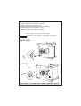
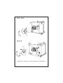
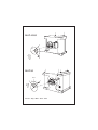
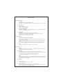
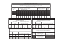
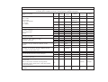
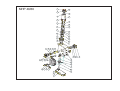
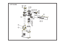
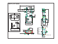
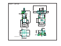
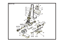
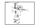
Cam Driven Systems
divisione della Bettinelli F.lli S.p.A.
Via Leonardo da Vinci, 56 - I - 26010
Bagnolo Cremasco (CR)
Tel. +39 0373 237311
Fax +39 0373 648303
E-mail: [email protected]
Internet: www.bettinelli.it
ISO 9001 - Cert. n° 1022
MANUALE PER USO E MANUTENZIONE MANIPOLATORI
SERIE MHP - LHP
MHP - LHP SERIES OPERATING
INSTRUCTIONS AND MAINTENANCE
GEBRAUCHS-UND WARTUNGSANLEITUNG FÜR
SCHEIBENKURVENGETRIEBE DER SERIE MHP - LHP
MANUEL D’UTILISATION ET D’ENTRETIEN
DES MANIPULATEURS SERIE MHP - LHP
MANUAL DE UTILIZACIÒN Y DE MANTENIMIENTO
DE LOS MANIPULADORES SERIE MHP - LHP
Prima edizione 10/99
MHP - LHP
FUM MHP-LHP
Controllo del ciclo con marcia / arresto
Check of the cycle with run / stop
Zyklunscontrolle mit start und stop das motore
Contrôle du cycle avec marche / arrêt
Control del ciclo con marcha / parada
Pausa - Dwell - Rast - Période d'arrêt - Pausa
Movimento - Index - Bevegung - Mouvement - Movimiento
MHP 40/60
=
=
á
H.D.
MHP 80
H.D.
=
=
á
H.D.( Half Dwell ) = Partenza - Start - Starten - Démarrage - Marcia
MHP 40/60
=
á
H.D.
=
MHP 80
H.D.
=
=
á
Spostamento - Displacement - Schalt - Déplacement - Desplazamento
MHP 40/60
=
á
=
H.D.
MHP 80
H.D.
=
=
á
Arresto - Stop - Halt - Arrêt - Paro
I
1. Avvertenze generali
1.1
Divieto di riproduzione
Il presente manuale è di proprietà della Bettinelli F.lli S.p.A. E' vietata la riproduzione o la
cessione a terzi del contenuto del presente documento. Tutti i diritti sono riservati.
1.2
Norme di riferimento
98/37/CE Direttiva Macchine
UNI EN 292 Sicurezza del Macchinario
1.3
Disposizioni a carico del cliente
Per una corretta installazione del Manipolatore fare riferimento alle norme sopra citate.
1.4
Indicazioni per interventi manutentivi
Per richiesta d'interventi manutentivi e per l'eventuale ordine di particolari di ricambio fare
riferimento a:
Cam Driven Systems divisione della Bettinelli F.lli S.p.A., Via Leonardo da Vinci, 56
26010 BAGNOLO CREMASCO (CR) - ITALIA
Tel. +39 0373 237311
Fax. +39 0373 648303
2. Caratteristiche tecniche
2.1
Dimensioni, baricentro e masse
Nella tabella Tab.01 vengono riportati le dimensioni d'ingombro, le quote indicative per la
determinazione del baricentro e le masse.
I valori del baricentro riportati in tabella si riferiscono a Manipolatori rotanti e/o lineari
standard. Nel caso di Manipolatori speciali (Es. predisposti per la motorizzazione, con alberi
speciali o con altri accessori) i valori riportati devono essere riconsiderati tenendo conto dei
singoli casi specifici.
2.2
Rumore
Il livello di pressione acustica continuo equivalente ponderato A, è inferiore a 70
3. Installazione
3.1
Immagazzinamento
I Manipolatori devono essere immagazzinati in ambiente asciutto e le superfici non verniciate
devono essere cosparse con olio protettivo antiossidante.
3.2
Movimentazione
La movimentazione dei Manipolatori avviene sollevando il gruppo tramite golfari conformi
alla norma UNI ISO 2947. Nella tabella Tab.02 vengono riportati il numero dei golfari, la
grandezza e la disposizione dei fori filettati necessari all'attacco dei dispositivi di sollevamento.
Il sollevamento avviene applicando i golfari nei fori filettati posizionati sulle superfici laterali.
3.3
Messa in servizio
Il Manipolatore deve essere fissato ad un supporto rigido e stabile tramite viti poste sul lato
inferiore della carcassa come da tabella Tab.03.
Inoltre i Manipolatori sono dotati di prefori spina posti nella parte inferiore della carcassa,
come da tabella Tab.03a per un migliore posizionamento e ancoraggio dello stesso.
3.4
Messa in funzione
3.4.1
Condizioni ambientali
Temperatura compresa tra 0° e 60°
3.4.2
Sostituzione tappo per olio
Prima della messa in servizio, sostituire il tappo per il foro di carico olio (colore nero), con
l'apposito tappo a sfiato fornito allegato al Manipolatore.
3.4.3
Trasmissione del moto
Particolare attenzione deve essere posta per il collegamento dell'albero in entrata al dispositivo
di moto. Quest'ultimo (riduttore, corona dentata etc..) deve essere collegato in modo tale da
garantire una totale assenza di giochi angolari e perfetta coassialità della trasmissione.
Un moto non omocinetico causa un'irregolare funzionamento dell'unità (urti, vibrazioni).
3.5
Messa fuori servizio
Togliere il lubrificante dal Manipolatore e provvedere all'eliminazione secondo la normativa di
riferimento relativa allo smaltimento degli oli (AGIP BLASIA 320).
4. Funzionamento
4.1
Destinazione e finalità per cui la macchina è stata prevista
I Manipolatori rotanti (serie MHP) sono componenti meccanici in cui il moto rotatorio
uniforme dell'albero in entrata viene trasformato in un moto intermittente od oscillatorio
combinato con una corsa verticale dello stelo.
Per quanto concerne i Manipolatori Lineari (LHP) sono componenti che trasformano il moto
rotatorio dell' MHP in moto orizzontale combinato con una corsa verticale della piastra
mobile.
4.2
Carichi statici
Il Manipolatore è fornito di una propria cuscinetteria ed è in grado di sostenere, carichi assiali e
momenti ribaltanti.
E' necessario che i valori di carico assiale e momento ribaltante propri dell'applicazione,
risultino inferiori ai valori massimi ammissibili che compaiono nella tabella Tab.04.
4.3
Momento torcente/Forza Assiale
Elemento determinante per un uso corretto e sicuro del Manipolatore è il rispetto del momento
torcente e della forza assiale ammissibili dovuti all'inerzia delle masse in movimento, all'attrito
ed alla presenza di forze di lavoro considerate come forze esterne al sistema.
Il momento torcente espresso in Nm e la forza assiale espressa in N, proprie d'ogni
Manipolatore, sono riportati nelle caratteristiche tecniche dell'unità assieme ai coefficienti
delle legge di moto Ca, Cv e Ck.
4.4
Rischi per usi impropri
Utilizzi del Manipolatore con valori di carico statico eccessivi (vedere 4.2) provocano:
- Non rispetto delle tolleranze di precisione
- Precoce usura della cuscinetteria
- Cedimento strutturale della cuscinetteria
Utilizzi del Manipolatore con valori di momento torcente e/o forza massima eccessivi
(vedere 4.3) provocano:
- Precoce usura del congegno (soprattutto perni folli)
- Danneggiamento o rottura dell'unità (perni folli e camma/divisore)
4.5
Rischi residui
I Manipolatori sono progettati al fine di rispondere ai requisiti di sicurezza della norma
UNI EN 292, rimangono alcuni rischi eliminabili unicamente all'atto dell'installazione del
Manipolatore nell'impianto di destinazione.
In particolare in funzione degli elementi mobili si possono presentare i seguenti rischi:
Elemento mobile Albero entrata moto
lato motorizzazione
Tipo di rischio:
Impigliamento
Trascinamento
Albero entrata moto
lato opposto mot.
Schiacciamento (*)
Cesoiamento (*)
Impigliamento
Trascinamento
Stelo d'alzata
Impigliamento
Trascinamento
Piastra Mobile
Schiacciamento (*)
Cesoiamento (*)
Impigliamento (**)
Trascinamento (**)
(*) L'insorgere di questo tipo di rischio è legato all'applicazione del micro e della camma di fase
(**) L'insorgere di questo tipo di rischio è relativo al Manipolatore Lineare
All'atto dell'installazione devono pertanto essere previste opportune protezioni per eliminare i
rischi sopra menzionati.
La scelta tecnica del tipo di protezione deve essere in funzione dell'applicazione e comunque
rispondente alle normative di riferimento.
4.6
Usi non consentiti.
L'uso corretto del Manipolatore, prevede l'avvio e l'arresto del ciclo nella fase di fermo.
Condizioni diverse di funzionamento possono provocare un aumento delle sollecitazioni con le
conseguenze riportate al punto 4.4.
Inoltre il Manipolatore viene fornito con ripari fissi che devono rimanere solidali al
Manipolatore durante il funzionamento dello stesso.
5. Manutenzione ordinaria
5.1
Manutenzione programmata
Per assicurarsi una buona efficienza del Manipolatore si raccomanda ogni 2.000 ore di
funzionamento ed a macchina ferma, il controllo del livello dell'olio lubrificante.
Si raccomanda inoltre di effettuare ogni 10.000 ore di funzionamento, sempre a macchina
ferma, la verifica di tutti i pezzi soggetti ad usura e la sostituzione dell'olio lubrificante (per le
unità lubrificate a grasso tale operazione non è necessaria).
Olio
AGIP BLASIA 320
Vedere disegni e tabella Tab.05.
6. Manutenzione straordinaria
6.1
Riparazione
Interventi di riparazione si rendono necessari in caso si avverta la presenza di gioco angolare in
una o più stazioni oppure si avverta un gioco superiore ai 0,3mm lungo il movimento verticale.
Tali inconvenienti sono dovuti al danneggiamento dei rulli/cuscinetti a causa di presenza di
sovraccarichi oppure arresto di emergenza e/o fuori pausa.
Per la sostituzione dei rulli/cuscinetti procedere nel seguente modo:
-
Portare l'albero entrata moto (12) a metà della fase di fermo ruotare l'albero (12) fino a non
rilevare il movimento dello stelo di alzata (90)
Caso A) problema di giochi in una o più stazioni; sostituzione permi/rulli (88/87) sul gruppo
MHP
- Allentare la vite di serraggio della ruota dentata (140) e svitare la vite del supporto pinzato
- Allentare la vite di serraggio del pinzato (223) ed estrarre verso l'alto il componente (fase
non previste per il gruppo MHP)
- Svitare le viti (211) ed estrarre verso l'alto la boccola di estremità (191)(8) con i rispettivi
commerciali
- Togliere il lubrificante della camera superiore del Manipolatore MHP40 e 60 (MHP80
comunicante)
- Svincolare il cappellotto (151) dalla carcassa (1) svitando le viti (216)
- Svitare le n.3 viti (116) di fissaggio del disco tenuta colonne (99) alle colonne per castello
(103)
MHP 40/60:
- Svitare le n.3 viti (182) di tenuta della colonna di alzata (176) al disco mobile (101)
- Svitare la ghiera (122) ed estrarre verso l'alto il disco mobile (101)
- Svitare le n.8 viti (61) e togliere verso l'alto il gruppo solidale alla boccola superiore (8);
prima di effettuare l'operazione descritta prendere nota della posizione dei rulli rispetto
alla fase di fermo della camma (4)
- Estrarre il perno (88) dal divisore (11); successivamente sfilare il rullo (87)
- Sostituire i perni (88) e rulli (87) danneggiati controllando che i fori di alloggiamento dei
perni nel divisore (11) siano ancora circolari e mantengano la loro precisione dimensionale.
In caso contrario è necessario sostituire anche l'intero divisore
- Per il riassemblaggio procedere in ordine inverso; nella fase descritta prestare attenzione
sia a fare alloggiare correttamente il rullo nella rispettiva sede presente sul disco di alzata
(97), sia di ingranare i rulli (87) nella corretta fassatura con la camma (4).
MHP 80:
-
Allentare le n.2 viti presenti nei rispettivi blocchetti fulcro leva (155) ed estrarre il perno
fulcro leva (156)
Svitare le n. 12 viti (68) di fissaggio del cuscinetto (27)(28); nell'eseguire l'operazione
prestare attenzione a lasciare avvitate le n.4 viti (66)(più corte delle altre) di fissaggio
della ralla superiore (27) per cuscinetto con la ralla inferiore (28) per cuscinetto.
Prendere nota della posizione della fase di fermo camma (4) sul disco divisore (11)
Svincolare il cuscinetto (27)(28) dall'alloggiamento della carcassa (1); nell'eseguire
l'operazione prestare attenzione ad estrarre i rulli dalla loro sede presente sul disco di alzata
(97)
Sfilare il disco di alzata (97) dalle rispettive n.3 colonne (103)
Estrarre il perno (88) dal divisore (11) svitando la rispettiva vite di tenuta del perno;
successivamente sfilare il rullo (87)
Sostituire i perni (88) e rulli (87) danneggiati controllando che i fori di alloggiamento dei
perni nel divisore (11) siano ancora circolari e mantengano la loro precisione dimensionale.
In caso contrario è necessario sostituire anche l'intero divisore
Per il riassemblaggio procedere in ordine inverso; nella fase descritta prestare attenzione
sia a fare alloggiare correttamente i n.2 rulli nella rispettiva sede presente sul disco di
alzata (97), sia ad inserire i rulli (87) solidali al divisore (11) nella posizione annotata
Caso B) Problema di giochi lungo il movimento verticale- intervento sui perni della leva;
sostituzione perni (88) sul gruppo LHP.
- Verificare il serraggio delle viti di fissaggio dei cuscinetti (232) e nel caso risultano
allentate
- Provvedere al loro serraggio; viceversa provvedere ad eseguire le fasi descritte di seguito
- Svitare la ghiera (230) ed estrarre il perno eccentrico (225) dalla rispettiva guida (226)
- Estrarre il perno (88) dalla sede presente sulla guida (226); successivamente sfilare il
cuscinetto (232)
- Sostituire il perno e cuscinetto danneggiato controllando che il foro di alloggiamento del
perno presente nella guida (226) sia ancora circolare e mantenga la precisione
dimensionale
- Procedere nell'ordine inverso per il riassemblaggio; durante la fase prestare attenzione a
riportare il medesimo valore di precarica dei rulli di guida dell'asta agendo sulla rotazione
del perno eccentrico (224).
N.B. Ripetere le fasi descritte anche per le restanti n.3 guide della piastra mobile (227)
Per quanto concerne gli interventi di sostituzione o manutenzione di parti meccaniche non
descritti nel presente fascicolo devono essere eseguiti nell'officina CDS.
GB - USA
1. General Information
1.1
Copyright
This manual is copyright of Bettinelli F.lli S. p. A.
Reproduction or assignment to third parties of this manual, in whole or in part, is forbidden
All rights reserved
1.2
Reference rules
98/37/EC Machinery Directive
UNI EN 292 Machinery Safety
1.3
Purchaser responsibilities
Purchaser is responsible for a correct installation of the rotating parts handler in conformity
with the above mentioned reference rules.
1.4
Manteinance
For manteinance and spare parts address the purchase order to:
Cam Driven Systems division of Bettinelli F.lli S.p.A. Via Leonardo da Vinci, 56
26010 BAGNOLO CREMASCO (CR) -ITALY
Phone +39 0373 237311 Fax +39 0373 648303
2. Technical features
2.1
Dimensions, center of gravity and weights
Please refer to the schedule (tab.01) for overall dimensions, approximate positions of the
center of gravity and weights
The values indicated in the above table correspond to the standard rotary and linear parts
handlers.
In case of special execution or parts handlers with accessories (e.g. part handlers with
special shafts or equipped with motoreducers) they must be considered time by time.
2.2
Noise
The level of continuous acoustic pressure is lower than 70 dBA
3. Installation
3.1
Storage
Rotating parts handlers must be stored in a dry room and the surfaces which have not been
painted must be protected to prevent oxiding.
3.2
Handling
The handling can be made by lifting eye bolts in conformity with UNI ISO 2947.
In the schedule (tab. 02) are indicated the quantity of eye bolts necessary per each type, the
size of thread and their position referred to sides of the part handler.
Lifting is done when all lifting eye bolts are in the screw holes.
3.3
Setup
The part handler must be fixed to a rigid support by bolts on the lower side of the housing, as
from schedule (tab. 03). For accurate positioning these units are supplied with pre-holes for
dowels on the bottom of the housing.
3.4
Starting
3.4.1
Ambient temperature
Working temperature range is from 0 to 60 C°
3.4.2
Oil plug replacement
The part handler is delivered with a plug to close the oil filling port.
Before to put in operation the part handler it is necessary to replace this plug (black color)
with the breather plug supplied with the parts handler.
3.4.3
Power transmission
Be sure to connect the input shaft to the driving gear properly. Power transmission (gearmotor,
sprocket etc...) connection must ensure absence of angular backlash and accurate aligment.
Unregular motion on the input shaft generates discontinuity of the motion ot the parts handler
as well as dangerous vibrations and shocks.
3.5
Out of service
Drain the lube oil (AGIP BLASIA 320) from the parts handler and discharge it according to the
oil waste disposal rules.
4. Running
4.1
Parts handlier performances
Rotating Parts Handlers (MHP) are mechanical units where uniform rotation of the input shaft
is transformed in an intermittent oscillating rotation of the output shaft combined with
lowering/rising stroke of the shaft.
Linear Parts Handlers ( LHP) are mechanical units transforming the motion characteristics of
the rotative type (MHP) in a combination of horizonthal stroke with lowering/rising of the
slide rail.
4.2
Static loads
The parts handler is equipped with bearings to support radial loads, axial loads and overturning
moments.
It is necessary that axial load, radial load and overturning moment values applied to the parts
handler are less than maximum allowable values shown in schedule (tab. 04).
4.3
Torque and Axial load
To use correctly and safely the parts handler is necessary that torque to overcome mass
inertia, friction and other external forces acting onto the system is less than the the output
torque capacity of the part handler istself.
Output torque in (Nm), axial load in (N), motion law coefficients Ca, Cv, Ck, of each parts
handler are indicated in the technical features.
4.4
Risks due to uncorrect use
If static loads applied to the parts handler are too high (see point 4.2), the risks are:
- Repeatability out of the tolerance
- Bearings early wear
- Bearing structural failure
If torque to overcome inertia, friction, other forcer, is too high (see point 4.3), the risks are:
- Parts handler early wear (cam followers in particular);
- Parts handler damage or breaking (cam followers and index mechanism).
4.5
Residual risks
Although the parts handlers are designed in conformity with UNI EN 292 standard safety
requirements, there are still some residual risks which can be eliminated only during parts
handler assembly on End User machine.
Particular caution is recommended when assembling movable parts to prevent the following
risks:
Movable part
Type of risk:
Input shaft
(transmission side)
Entangling
Dragging
Input shaft
(rear side)
Squashing (*)
Shearing (*)
Entangling
Dragging
Output shaft
Entangling
Dragging
Movable plate
Squashing (*)
Shearing (*)
Entangling (**)
Dragging (**)
(*) This type of risk is related to the cycle on demand actuated by microswitch and trip cam.
(**) This risk is related to the Linear Manipulator (LHP).
To prevent the above mentioned risks, it is recommended that the End User provides for
suitable safety protection devices. Type of safety protection devices is related to the type of
application and however shall be in accordance with the official Norms.
4.6
Unauthorized uses
To use correctly the parts handler is necessary start and stop in dwell. Different operation
conditions generates higher stress with consequences as indicated in section 4.4.
In addition, the parts handler is supplied with fixed safety protection that must remain fixed
during the running.
5. Ordinary maintenance
5.1
Scheduled maintenance
To ensure long machine life of the parts handler, every 2000 working hours or when it is in
stand by, it is recommended that the user checks the lube oil level.
In addition, every 10000 working hours, it is recommended that the user checks all parts
subject to wear and to replaces the lube oil.
Oil
AGIP BLASIA 320
See drawing and schedule (tab. 05).
6. Special maintenance
6.1
Repair
Repair is necessary when there is angular backlash in the positioning at the working stations or
in case that the mechanism of lowering /rising has backlash higher than 0.3 mm
Generally, the presence of backlash means that followers and bearings are damaged due to
overloading or emergency stops out of dwell.
To replace followers and bearings operate as follows:
- Bring the input cam shaft (12) up to the middle of the dwell phase (the cam shaft (12) is in
dwell when its rotation doesn't generate any movement of the output shaft (90) )
Case A) Backlash on one or more stations; replacement of the cam followers (88/87) of an
MHP
- Loosen the locking screw of the gear (140) and loosen the screw of the clamp.
- Loosen the screw of the clamp (223) and draw out upward the component (not to be
considered for the MHP)
- Unscrew the the screws (211) and draw out upward the flanges (191) (8) with hardware.
- Drain the lubricant from the upper chamber of the Parts Handler MHP 40 and MHP 60 (in
MHP 80 the two chanbers are connected together)
- Unlock the cap (151) from the housing (1) by unscrewing the screws (216)
- Unscrew the 3 screws (116) fixing the upper holding flange to the columns (103)
MHP 40/60:
- Unscrew the 3 screws (182) fixing the lowering/rising stem (176) to the mobile dial plate
(101)
- Unscrew the iron ring (122) and draw out upward the mobile dial plate (101)
- Unscrew the 8 screws (61) and draw out upward the the part connected with the support
flange (8); before to make this operation identify the reference assembly position of the
followers in relation to the dwell phase of the cam (4).
- Draw out the stud (88) from the turrett (11) and disassemble the follower (87).
- Replace the damaged studs (88) and rollers (87), check the roundness of the seat holes and
the geometry of their axis. If seat holes are deformated or geometric position of their axis
is uncorrect the turret and the follower wheel must be replaced.
- To reassemble you can proceed in the same way in opposed order.
Care specifically that the follower will be correctly inserted in seat in the lifting ring (97)
as well as to locate in the right position the followers (87) in the cam profile (4).
MHP 80:
- Loosen the 2 screws of the lever pivot blocks (155) and draw out the pin (156)
- Unscrew the 12 fixing screws (68) of the bearing (27)(28). During this operation be
careful to leave screwed the 4 fixing screws (66) (these screws are shorter than the others)
connecting the 2 rings ( the upper and the lower (27-28)) of the bearing.
- Identify the reference assembly position of the cam dwell phase (4) on the followers wheel
(11).
- Draw out the bearing (27)(28) from its seat on the housing; during this operation be
careful to draw out the rollers from their seat in the lifting ring (97).
- Draw out the lifting ring (97) from the 3 columns (103)
- Disassemble the pin (88) from the follower wheel (11) unscrewing the rear locking screw
then draw out the follower (87)
- Replace the pins (88) and rollers (87) damaged. Check the roundness of the seat holes and
the geometry of their axis. If seat holes are deformated or geometric position of their axis
is uncorrect the turret and the follower wheel must be replaced.
- To reassemble you can proceed in the same way in opposed order.
Care specifically to insert correctly the 2 rollers in their seat of the lifting ring (97) and to
insert the followers (87) of the follower wheel (11) in the reference position previously
identified.
Caso B) Backlash of the output lowering/rising shaft - manteinance of the pins on the lever replacement of the followers (88) - parts handler LHP
- Check the tightening of the assembly bolts of the bearing (232); if they are loosen lock
them. If not follow the operations explained below.
- Unscrew the locking nut (230) and draw out the eccentric pin (225) from guide (226).
- Draw out the pin (88) from its seat on the guide (226); then disassemble the bearing (232)
- Replace the pin and the damaged follower checking the roundnes of its seat on the guide
(226).
- To reassemble you can proceed in the same way in opposed order. During this phase care
specifically to preload equally all the followers on the rail. Preload force is regulated by the
rotation of the eccentric stem of the follower.
N.B.: Act in the same way for the remaining 3 guides to the rail (227)
Different tuning or maintenance of other mechanical parts must be done in CDS workshop
or authorized repair center.
D
1. Allgemeine Hinweise
1.1
Vervielfältigungsverbot
Die vorliegende Anleitung ist Eigentum der Bettinelli F.lli S.p.A.
Vervielfältigung oder Weitergabe an Dritte des Inhalts der vorliegenden Veröffentlichung
sind verboten. Alle Rechte vorbehalten.
1.2
Bezugsnormen
98/37/EG Maschinenrichtlinie
UNI EN 292 Sicherheit der Maschinenanlagen
1.3
Auflagen für den Kunden
Zur korrekten Installation des Schwenk-Übergabegeräts müssen die obengenannten
Normen beachtet werden.
1.4
Hinweise für Wartungseingriffe
Um Wartungseingriffe oder Ersatzteile anzufordern, setzen Sie sich in Verbindung mit:
Bettinelli F.lli S.p.A. Abteilung Cam Driven Systems, Via Leonardo da Vinci, 56
26010 BAGNOLO CREMASCO (CR) - ITALY
Tel + 39 0373 237311
Fax +39 0373 648303
2. Technische Daten
2.1
Außenmaße, Schwerpunkt und Gewicht
In der Tabelle 01 sind die Außenmaße, die Positionen zur Bestimmung des
Schwerpunkts und das Gewicht angegeben.
Obengenannte Werte beziehen sich auf Standardausführungen; im Falle von
Sonderausführungen (z.B für Motorisierung vorgesehene, mit besonderen Wellen oder
anderen Besonderheiten) müssen diese Werte für jede einzelne Ausführung neu
durchdacht werden.
2.2
Geräuschpegel
Der anhaltende Geräuschpegel liegt unter 70 dB.
3. Installation
3.1
Lagerung
Die Schwenk-Übergabegeräte müssen in trockener Umgebung gelagert werden.
Unlackierte Oberflächen müssen mit Rostschutzmittel bestrichen werden.
3.2
Versetzung
Die Versetzung der Schwenk-Übergabegeräte erfolgt, indem die Einheiten mittels
Ösenschrauben gemäß UNI ISO 2947 angehoben werden. In der Tabelle 02 sind die Anzahl
Ösenschrauben, die Größe und die Anordnung der Gewindebohrungen zur Verankerung der
Hubvorrichtungen angegeben. Zum Anheben müssen die Ösenschrauben in den
Gewindebohrungen auf den Seiten befestigt werden.
3.3
Instandsetzen
Das Schwenk-Übergabegerät muß mittels der Schrauben an der Unterseite des Gehäuses
an einer festen und stabilen Tragevorrichtung gemäß Tabelle 03 befestigt werden.
Um besser aufgestellt und verankert zu werden, verfügen die Schwenk-Übergabegeräte an der
Unterseite des Gehäuses außerdem über Vorbohrungen für Bolzen, wie in der Tabelle 03a
angegeben.
3.4
Ingangsetzen
3.4.1
Arbeitsumgebung
Temperatur muß zwischen 0° und 60° begriffen sein.
3.4.2
Austausch des Öldeckels
Bei den durch Öl geschmierten Schwenk-Übergabegeräten muß vor dem Ingangsetzen der
Deckel mit dem Einfülloch für das Öl (schwarz) durch den besonderen, mit dem SchwenkÜbergabegerät mitgelieferten Entlüfterdeckel ersetzt werden.
3.4.3
Bewegungsübertragung
Beim Anschließen der Eingangswelle an die Bewegungsvorrichtung ist besondere
Aufmerksamkeit gefordert. Letztere (Untersetzungsgetriebe oder Zahnkranz) müssen so
angeschlossen werden, daß jeglicher Torsionsspielraum ausgeschlossen und die perfekte
Koaxialität der Übertragung garantiert ist. Ist dieBewegung nicht gleichlaufend, kann sie eine
ungleichmäßige Bewegung der Einheit (Stöße, Vibrationen) hervorrufen.
35
Außer Betrieb setzen
Das Schmiermittel aus dem Schwenk-Übergabegerät entfernen und es gemäß den Normen zur
Entsorgung von Mineralölen (AGIP BLASIA 320) vernichten.
4. Funktionsweise
4.1
Anwendungsgebiete der Maschine
Die rotierenden Schwenk-Übergabegeräte (Serie MHP) sind mechanische Komponenten, in
denen die gleichförmige Drehbewegung der Eingangswelle in eine intermittierende oder
oszillatorische Bewegung der Ausgangswelle mit senkrechtem Hub des Schafts umgewandelt
wird. Die linearen Schwenk-Übergabegeräte (Serie LHP) sind mechanische Komponenten, in
denen die rotierende Bewegung der MHP in eine horizontale Bewegung mit senkrechtem Hub
der beweglichen Platte umgewandelt wird.
4.2
Statische Belastungen
Die Schwenk-Übergabegeräte sind mit eigenen Lagern versehen, wodurch sie axialen
Belastungen sowie Kippmomenten ausgesetzt werden können. Es ist notwendig, daß die der
einzelnen Ausführung eigenen Werte an axialer Belastung und Kippmoment niedriger sind als
die höchst zulässigen Werte, wie sie in Tabelle 04 aufgeführt sind.
4.3
Drehmoment
Ein ausschlaggebendes Element für die korrekte und sichere Benutzung der SchwenkÜbergabegeräte ist die Einhaltung des zulässigen Drehmoments und der axialen Belastung, die
von der Trägheit der bewegten Massen, von der Reibung und von systemfremden
Arbeitskräften abhängt.
Das Drehmoment in Nm und die axiale Belastung in N sind für jede Ausführung spezifisch und
werden in den Betriebsdaten der Einheit zusammen mit den Koeffizienten des
Bewegungsgesetzes Ca, Cv und Ck angegeben.
4.4
Risiken bei unsachgemäßem Gebrauch
Das Betreiben der Schwenk-Übergabegeräte mit zu hohen statischen Belastungen (siehe 4.2)
führt zu:
- Nicht-Einhaltung der Präzisionsabweichungen
- Vorzeitigem Verschleiß der Lager
- Beschädigung der Lager
Das Betreiben der Schwenk-Übergabegeräte mit zu hohen Drehmomenten und/oder
übermäßiger Höchstbelastung (siehe 4.3) führt zu:
- Vorzeitigem Verschleiß der Vorrichtung (v.a. Zapfen)
- Schaden oder Bruch des Schwenk-Übergabegerätes (v.a. Zapfen und Nocken)
4.5
Sonstige Risiken
Die Schwenk-Übergabegeräte sind so entworfen, daß sie den Sicherheitsanforderungen der
UNI EN 292-Norm entsprechen. Es bleiben einige Risiken, die nur im Moment der Installation
im Zielwerk behoben werden können.
Insbesondere können in bezug auf die beweglichen Teile folgende Risiken auftreten:
BewegIiches
TeiI
Risikotyp:
Antriebswelle
Seite des Motors
Verhaken
Mitnahme
Antriebswelle
Seite gegenüber Motor
Quetschung (*)
Schnitt (*)
Verhaken
Mitnahme
Schaft
Bewegliche Platte
Verhaken
Mitnahme
Quetschung (*)
Schnitt (*)
Verhaken (**)
Mitnahme (**)
(*) Das Auftreten dieses Risikotyps ist an die Anwendung des Mikro und des Phasennockens
gebunden.
(**) Das Auftreten dieses Risikotyps bezieht sich auf das lineare Schwenk-Übergabegerät.
Infolgedessen müssen bei der Installation geeignete Schutzmaßnahmen gegen obengenannte
Risiken vorgesehen werden.
Die Auswahl der Schutzmaßnahmen muß unter technischen und anwendungsspezifischen
Gesichtspunkten geschehen, wobei auf jeden Fall die Bezugsnormen beachtet werden
müssen.
4.6
Unerlaubte Anwendungen
Der korrekte Gebrauch der Schwenk-Übergabegeräte sieht Anlassen und Ausschalten des
Zyklus im Rastzustand vor.
Andere Betriebsbedingungen können eine Zunahme der Beanspruchung mit den in Punkt 4.4
aufgeführten Folgen hervorrufen.
Außerdem wird das Schwenk-Übergabegerät mit festen Schutzplatten geliefert, die während
des Betriebs daran befestigt bleiben müssen.
5. Gewöhnliche Wartung
5.1
Vorgesehene Wartung
Um sich der reibungslosen Betriebsweise des Schwenk-Übergabegeräts zu versichern, ist es
empfehlenswert, alle 2000 Betriebsstunden bei stehender Einheit, den Ölstand zu überprüfen.
Weiterhin wird empfohlen, alle 10 000 Betriebsstunden, wiederum bei stehender Einheit, alle
Verschleißteile zu kontrollieren und das Schmieröl auszuwechseln (bei SchwenkÜbergabegeräten. die mit Fett geschmiert werden, ist das nicht nötig).
Öl
AGIP BLASIA 320
Siehe Zeichnungen und Tabelle 05.
6. Außergewöhnliche Wartung
6.1
Reparatur
Reparaturen sind dann notwendig, wenn man an einer oder mehreren Stationen Winkelspiel
bzw. längs des senkrechten Hubs ein Spiel von mehr als 0,3 mm bemerkt.
Diese Unannehmlichkeiten sind auf die Schädigung der Laufrollen/Lager zurückzuführen
aufgrund einer zu hohen Belastung oder eines Nothalts und/oder Anhalten außer der
Rastphase. Zum Austausch der Laufrollen/Lager wird empfohlen, wie folgt vorzugehen:
-
Drehen Sie die Eingangswelle (12) bis zur Mitte der Rastphase. Die Welle (12) drehen bis
keine Bewegung des Schafts (90) mehr wahrgenommen wird.
Fall A) Tritt Spiel an einer oder mehreren Stationen auf, müssen die defekten
Bolzen/Laufrollen (88/87) an den MHP ausgetauscht werden.
- Klemmschraube vom Zahnrad lösen (140) und Schraube von der Zwinge losschrauben.
- Klemmschraube von der Zwinge (223) lösen und Komponenten nach oben herausziehen
(bei MHP nicht zu berücksichtigen)
- Schrauben (211) lösen und den Endflansch (191) (8) mit den zugehörigen Handelsteilen
nach oben herausziehen.
- Schmiermittel von der oberen Kammer des Übergabegeräts MHP40 und 60 entfernen.
(Beim MHP 80 sind zwei Kammern miteinander verbunden.)
- Schrauben (216) des oberen Deckels (151) lösen, anschließend kann der Deckel vom
Gehäuse (1) abgenommen werden.
- 3 Schrauben (116) zur Befestigung der Platte (99) an der Säule (103) lösen.
MHP 40/60:
- 3 Schrauben (182) zur Befestigung der festsitzenden Säule (176) an der beweglichen
Platte (101) lösen.
- den Ring (122) abschrauben und die bewegliche Platte (101) nach oben herausziehen.
-
8 Schrauben (61) lösen und das mit der Büchse (8) verbundene Teil nach oben
herausnehmen. Bevor man diese Operation durchführt, sollte man sich die Position der
Laufrollen im Zusammenhang zur Position der Schaltkurve (4) (Rastphase) notieren.
Bolzen (88) vom Schaft (11) herausnehmen, anschließend die Laufrolle (87) abziehen.
defekte Bolzen (88) und Laufrolle (87) austauschen, Überprüfung der
Aufnahmebohrungen im Schaft (11) auf Genauigkeit und Maßhaltigkeit. Andernfalls den
Schaft (11) komplett austauschen.
Zur Montage dieselben Schritte in umgekehrter Reihenfolge ausführen. Dabei beachten,
daß die Seite und Position/Phase der Laufrollen zur Hubscheibe (97) im Zusammenhang
mit den Schaltkurven (4) und den Laufrollen (87) stimmen.
MHP 80:
- 2 Schrauben vom Drehhebel (155) lösen und zugehörigen Bolzen herausnehmen.
- 12 Befestigungsschrauben (68) vom Lager (27) (28) lösen. Bei dieser Operation darauf
achten, die 4 kürzeren Schrauben (66) zur Befestigung der oberen Spurpfanne (27) mit
der unteren Spurpfanne (28) nicht abzuschrauben.
- Die Position der Rastphase der Schaltkurve (4) am Abtriebsflansch (11) notieren.
- Lager (27) (28) aus dem Sitz des Gehäuses herausnehmen, während dieser Operation
vorsichtig die Laufrollen vom Sitz der Hubscheibe (97) abziehen.
- Hubscheibe (97) von den 3 Führungssäulen (103) abnehmen
- Den Bolzen (88) durch Abschrauben der entsprechenden Befestigungsschraube vom
Abtriebsflansch (11) lösen, dann die Laufrolle (87) herausnehmen.
- Defekte Bolzen (88) und Laufrolle (87) austauschen, Überprüfung der
Aufnahmebohrungen im Abtriebsflansch (11) auf Genauigkeit und Maßhaltigkeit.
Andernfalls den Abtriebsflansch (11) komplett austauschen.
- Zur Montage dieselben Schritte in umgekehrter Reihenfolge ausführen. Dabei sowohl
darauf achten, daß die 2 Laufrollen in der richtigen Seite in der Hubscheibe (97) sitzen
als auch, daß die am Abtriebsflansch (11) befestigten Laufrollen (87) in der notierten
Position einrasten.
Fall B) Tritt Spiel bei der Hubbewegung auf (Austausch der Hebelbolzen; Austausch der
Bolzen (88) am LHP).
- Befestigungsschrauben der Lager (232) überprüfen; haben sich die Schrauben gelöst,
festziehen.
- Sind nicht die Laufrollen die Ursache hierfür, folgen Sie der unten angegebenen
Erklärung.
- Nutmutter (230) lösen und Exzenterbolzen (225) von der Führung (226) herausnehmen.
- Den Bolzen (88) von seinem Sitz in der Führung (226) lösen und das Lager (232)
abziehen.
- Defekte Bolzen und Lager austauschen, Überprüfung der Aufnahmebohrung in der
Führung (226) auf Genauigkeit und Maßhaltigkeit.
- Zur Montage dieselben Schritte in umgekehrter Reihenfolge ausführen. Dabei darauf
achten, daß die Führungsrollen des Hebels denselben Spannungswert einhalten, indem
auf die Drehung des Exzenterbolzens (224) eingewirkt wird.
N.B. Selbe Vorgehensweise mit den 3 Führungen der beweglichen Platte (227).
Etwaige Reparaturen oder Instandhaltungen von Ersatzteilen, die nicht in der vorliegenden
Anleitung beschrieben sind, müssen dann in der CDS Reparaturwerkstatt erledigt werden.
F
1. Généralités
1.1
Reproduction interdite
Ce manuel est propriété de la société Bettinelli F.lli S.p.A.
Toute reproduction ou transmission du contenu de ce document est interdite.
Tous droits réservés.
1.2
Normes de référence
98/37/CE Directive Machines
UNI EN 292 Normes de sécurité pour les machines
1.3
Responsabilités du client
L' installation du manipulateur rotatif est sous la responsabilité du client. Voir normes de
référence ci-dessus.
1.4
Service d'entretien
Pour une demande d'entretien et pour la commande de pièces de rechange s'adresser à:
Cam Driven Systems division de la société Bettinelli F.lli S.p.A. Via Leonardo da Vinci, 56
26010 BAGNOLO CREMASCO (CR) -ITALY
Tel. +39 0373 237311 Fax +39 0373 648303
2. Caractéristiques techniques
2.1
Dimensions, barycentre et poids
Dans le tableau 01 sont indiqués les dimensions des manipulateurs et les positions indicatives
qui permettent de calculer le barycentre et les différents poids.
Les valeurs indiquées ci-dessus se réfèrent aux manipulateurs rotatifs et/ou linéaires standard.
Dans le cas de manipulateurs spécifiques (par ex .prédisposés à la motorisation ou déjà
motorisés, équipés d'arbres spéciaux, ou d'autres accessoires) les valeurs ci-dessus doivent être
adaptées à chaque cas en particulier.
2.2
Bruit
Le niveau de pression acoustique continue est inférieur à 70dB.
3. Installation
3.1
Stockage
Les manipulateurs doivent être stockés dans un environnement sec et les surfaces non-peintes
doivent être protégées par une couche d'huile protectrice antirouille.
3.2
Manipulation
Pour déplacer les manipulateurs, soulever le groupe tout entier à l'aide de vis à oeillets
conformes aux normes UNI ISO 2947.
La référence et la grandeur des vis à oeillet ainsi que la position des trous filetés nécessaires à
l'accrochage des dispositifs de soulèvement sont indiqués dans le tableau 02.
Pour cette opération enfiler les vis à oeillets dans les trous filetés se trouvant sur les surfaces
latérales.
3.3
Mise en service
Le manipulateur doit être fixé à un support rigide et stable à l'aide de vis se trouvant sur le côté
inférieur de la carcasse et suivant les indications du tableau 03.
Par ailleurs, les manipulateurs sont pourvus de prè-trous situés sur la partie inférieure de
la carcasse, voir tableau 03 pour un ancrage et un positionnement correct.
3.4
Mise en fonctionnement
3.4.1
Conditions de température
Température comprise entre 0 et 60 C°.
3.4.2
Changement du bouchon de l'huile
Avant de mettre en service le manipulateur, remplacer le bouchon de l'huile (couleur noire) par
le bouchon ventouse fourni avec le manipulateur.
3.4.3
Transmission du mouvement
Faire particulièrement attention au dispositif de mouvement lors du montage de l'arbre
d'entrée. Ce dispositif (réducteur, couronne dentée, etc.) doit être monté de façon à garantir une
absence totale de jeu angulaire et une parfaite transmission concentrique.
Un mouvement non homocinétique pourrait provoquer un fonctionnement irrégulier du groupe
(chocs, vibrations, etc...)
3.5
Mise hors service
Retirer le lubrifiant du manipulateur et réaliser la vidange selon les normes de référence
relatives à l'évacuation des huiles (AGIP BLASIA 320).
4. Fonctionnement
4.1
Performances du manipulateur
Les manipulateurs (série MHP) rotatifs sont des composants mécaniques qui, grâce au
mouvement rotatif uniforme de l'arbre d'entrée, engendrent un mouvement rotatif intermittent
ou oscillant accompagné d'une course verticale de la tringle. Les manipulateurs linéaires (LHP)
eux, ont la fonction de transformer le mouvement rotatif de l'MHP en un mouvement
horizontal avec un développement de course du disque mobile verticale.
4.2
Charges statiques
Le manipulateur est équipé d'un ensemble de roulements afin de pouvoir supporter des charges
axiales et des couples de renversement.
Les valeurs de charge axiale et du couple de renversement doivent être inférieures aux
valeurs maxi admises et indiquées dans le tableau 04.
4.3
Couple de torsion / force axiale
Une utilisation correcte et sûre des manipulateurs nécessite le respect de couple de torsion et de
la force axiale admis et dus à l'inertie des poids en mouvement, au frottement et à la présence
de forces de travail considérées externes au système.
Dans les caractéristiques techniques de chaque manipulateur se trouvent les valeurs de couple
de torsion et la force axiale exprimées en Nm, ainsi que les coefficients des lois de mouvement
Ca, Cv et Ck.
4.4
Risques par utilisation impropre
L'utilisation des manipulateurs avec des valeurs excessives de charge statique (voir 4.2)
provoque:
- Le non-respect des tolérances de précision;
- Une usure précoce du roulement;
- Une rupture des roulements.
L'utilisation des manipulateurs avec des valeurs excessives de couple de torsion et/ou de
force maxi (voir 4.3) provoque:
- Une usure précoce du manipulateur (spécialement pour les galets de came)
- Des dommages au manipulateur, voir rupture totale du groupe (des galets de came et
came/diviseur)
4.5
Risques qui subsistent encore
Les manipulateurs répondent aux exigences de sécurité de la norme UNI EN 292.
Toutefois, quelques risques demeurent encore et sont à éliminer lors du montage du
manipulateur dans son implantation finale.
Il est donc recommandé de faire attention lors du montage des éléments mobiles afin d'éviter
les risques suivants:
Elément mobile Arbre d'entrée
mouvement côté
motorisation
Type de risque:
Accrochage
Traînée
Arbre d'entrée
mouvement côté
opposé motor.
Ecrasement (*)
Coupure (*)
Accrochage
Traînée
Tringle de
soulèvement
Disque mobile
Accrochages
Traînée
Ecrasement (*)
Coupure (*)
Accrochages (**)
Traînée (**)
(*) Ce type de risque est lié à l'application du micro-switch et de la came de phase.
(**) Ce type de risque concerne les manipulateurs linéaires
Afin d'éviter les risques mentionnés ci-dessus, lors du montage il faut prévoir l'installatione
protections. Le choix technique du type de protections doit être effectué en
fonction de leur application et doit répondre aux normes de référence mentionnées
antérieurement.
4.6
Usages interdits
L'usage correct du manipulateur prévoit le démarrage et l'arrêt du cycle en phase de période
d'arrêt. Des conditions différentes de fonctionnement peuvent provoquer une augmentation des
contraintes avec les conséquences citées au paragraphe 4.4 ci-avant.
Le manipulateur est équipé de protections fixes devant rester fixées au manipulateur pendant
son fonctionnement.
5. Entretien ordinaire
5.1
Entretien préventif
Afin d'assurer le bon rendement du manipulateur, il est conseillé de contrôler le niveau de
l'huile lubrifiant toutes les 2.000 heures de fonctionnement et avec unité arrêtée.
Il est également conseillé de vérifier l'état de toutes les pièces soumises à usure et de changer
l'huile lubrifiant toutes les 10.000 heures de fonctionnement. Réaliser ces opérations avec
machine arrêtée. Pour les manipulateurs lubrifiés à la graisse, de telles opérations ne sont pas
nécessaires.
Huile
AGIP BLASIA320
Voir croquis et tableau 05.
6. Entretien supplémentaire
6.1
Réparation
Lorsque se vérifie le présence de jeu angulaire dans une ou plusieurs stations, ou lorsque le jeu
dépasse les 0,3 mm long du mouvement vertical, une réparation se doit d'être effectuée.
De tels inconvénients sont dus à l'usure des galets/roulements engendrée soit par la présence
de surcharges, soit par un arrêt d'urgence hors période d'arrêt.
Pour remplacer les galets/roulements procéder de la façon suivante:
-
Amener l'arbre d'entrée mouvement (12) jusqu'à la moitié de la période d'arrêt, faire
tourner l'arbre 12 jusqu'à ce que la tringle de soulèvement (90) soit fixe
Cas A) - Problème de jeu dans une ou plusieurs stations: remplacer les galets/roulements (88/
87) du groupe MHP
- Desserrer la vis de serrage de la roue dentée (140) et dévisser la vis du groupe de coinçage
- Desserrer la vis de serrage du groupe de coinçage (223) et extraire le composant (étape non
prévue pour le groupe MHP)
- Dévisser les vis (211) et extraire la douille d'embout (191) (8) à l'aide d'outils appropriés.
- Effectuer la vidange de l'huile de la chambre supérieure du manipulateur MHP 40 et 60
(MHP 80 communiquant)
- Dégager la capuche (151) de la carcasse (1) en dévissant les vis (216)
- Dévisser les trois vis (116) de fixage du disque de soutien de la colonne (99)
MHP-40/60:
- Dévisser les trois vis (182) du disque de retenue de la colonne de soulèvement (176)
- Dévisser la frette (122) et extraire le disque mobile (101)
- Dévisser les huit vis (61) et extraire le groupe solidaire de la douille supérieure (8): avant
d'effectuer cette opération repérer la position des galets par rapport à la phase de
verrouillage de la came (4)
- Extraire le galet (88) du diviseur (11); ensuite faire défiler le roulement (87)
- Remplacer les galets (88) et les galets (87) détériorés en vérifiant si les enceintes des galets
dans le diviseur sont encore arrondies et si leurs dimensions sont encore correctes; dans le
cas contraire il faudra remplacer le diviseur
-
Procéder en sens inverse pour remonter le tout; faire bien attention à fixer correctement le
galet dans le trou situé sur le disque de soulèvement (97) et à bien engager les galets (87)
par rapport à la came (4)
MHP-80:
- Desserrer les deux vis des sabots de point d'appui (155) et extraire le galet de point d'appui
(156)
- Dévisser les deux vis (68) de fixage du roulement (27) (28); faire bien attention à laisser
fixes les quatre vis (66) (plus courtes que les autres) de fixage de la butée supérieure de
roulement (27) avec la butée inférieure de roulement (28)
- Repérer la position de la phase de verrouillage de la came (4) sur le disque diviseur (11)
- Dégager le roulement (27) (28) de l'enceinte de la carcasse (1); faire attention à bien
extraire les galets de leurs enceinte du disque de soulèvement (97)
- Faire défiler le disque de soulèvement (97) le long des trois colonnes (103)
- extraire le galet (88) du diviseur (11) en dévissant la vis de soutien; ensuite enlever le galet
(87)
- Remplacer les galets (88) et les galets (87) détériorés en contrôlant si les trous de fixage
du diviseur (11) ont encore une forme arrondie et s'ils ont encore des dimensions correctes.
Dans le cas contraire remplacer également l'intérieur du diviseur.
- Pour remonter le tout procéder en sens inverse; faire très attention à bien installer les deux
galets dans leur enceinte et à bien placer les galets (87) solidaires au diviseur (11) dans la
position indiquée
Cas B) - Problèmes de jeu le long du mouvement vertical - intervention sur les galets de
soulèvement; remplacement des galets (88) sur le groupe LHP
- Contrôler que les vis de fixage des roulements (232) soient bien serrées et dans le cas
contraire les revisser;
- Dévisser la frette (230) et extraire le galet décentré (225) hors de son guidage (226)
- Extraire le galet (88) hors de son guidage (226); ensuite faire défiler le roulement (232)
- Remplacer le galet et le roulement détérioré en contrôlant que le trou de logement du galet
soit encore arrondi et que ses dimensions soient encore correctes;
- Procéder en sens inverse pour remonter le tout; pendant cette phase reporter la même
valeur de précharge des galets de guidage de la tringle en intervenant sur la rotation du
galet décentré (224)
N.B. Répéter les étapes décrites ci-avant pour les 3 guidages restants du disque mobile (227)
En ce qui concerne la substitution et l'entretien des parties mécaniques qui ne sont pas
signalées dans ce fascicule, elle devront être réalisées aux ateliers CDS.
S
1. Informaciones generales
1.1
Reproducción prohibida
Este manual es propiedad de la empresa Bettinelli F.lli S.p.A.
Se prohibe copiar o transmitir a terceros el contenido del presente manual.
Todos los derechos reservados.
1.2
Normas de referencia
98/37/CE Direcriva Máquinas
UNI EN 292 Normas de seguridad de las máquinas
1.3
Responsabilidades del cliente
La instalación del manipulador giratorio está bajo la responsabilidad del cliente.
Ver las normas de referencia citadas arriba.
1.4
Servicios de mantenimiento
Para solicitar un servicio de mantenimiento o bien para el pedido de piezas de recambio
dirigirse a:
Cam driven Systems divisione de la Bettinelli F.lli S.p.A. Via Leonardo da Vinci, 56
26010 BAGNOLO CREMASCO (CR) -ITALY
Tel. +39 0373 237311 Fax +39 0373 648303
2. Características técnicas
2.1
Dimensiones, baricentro y pesos
En el cuadro 01 se indican las dimensiones totales del manipulador y las posiciones indicativas
para determinar el baricentro y los pesos.
Los valores arriba indicados se refieren a manipuladores standard; en caso de manipuladores
especiales (por ej predispuestos a la motorización o ya motorizadod, con ejes especiales o con
otros accesorios) estos valores tienen que ajustarse a cada caso específico.
2.2
Ruido
El nivel de presión acústica continua es inferior a 70dB.
3. Instalación
3.1
Almacenamiento
Los manipuladores tienen que almacenarse en un lugar seco y las superficies sin pintar
tienen que recubrirse con un aceite protecior antioxidante.
3.2
Movimentacion
La movimentacion de los manipuladores sucede levantando la unidad por medio de los
“golfaros”, estrumento conforme a la norma UNI ISO 2947. En cuadro tab.2 se riporta el
numero de “golfaros”, el tamano y la disposicion de los agujeros roscados que necesitan por
fijar los dispositivos de levantamiento.
El levantamiento sucede ponendo los “golfaros” en los apositos agujeros roscados que esta
posicionados en angulos de las caras laterales.
3.3
Puesta en servicio
El manipulador ha de ser fijado sobre un soporte rigido y firme por medio de tornillos
posiccionados sobre el lado inferior de la caja come se ver en cuadro tab.03.
Ademas los manipuladores estan provistos de preagujeros por enchufes puestos en el lado
inferior de la caja, como se ver en cuadro tab.03a por una mejor posiccion fija y firma de lo
mismo.
3.4
Puesta en funcionamiento
3.4.1
Condiciones de temperatura
Temperatura comprendida entre 0° y 60 C°.
3.4.2
Cambio del tapón de aceite
Antes de poner en servicio los manipuladores lubrificados con aceite hay que sustituir el tapón
de llenado (color negro) por el tapón purgador adecuado suministrado con el manipulador.
3.4.3
Transmisión del movimiento
Hacer mucha atención al ensamblar el eje de entrada con el dispositivo de movimiento.
Este útimo (reductor o corona dentada) tiene que acoplarse perfectamente afin de evitar juegos
angulares y garantizar una perfecta concentricidad en la transmisión. Un movimiento no
omocinetico provoca un funcionamento no regular de la unidad (choques, vibraciones).
3.5
Puesta fuera de servicio
Sacar el labrificante del manipulador y efectuar el vaciado según las normas de referencia
relativas a la evacuación de aceites ( AGIP BLASIA 320).
4. Funcionamiento
4.1
Prestaciones de la mesa
Los manipuladores giratorios son componentes mecánicos en los cuales el movimiento
rotatorio del eje de entrada se transforma en un movimiento rotatorio intermitente u oscilatorio
con recorrido vertical del disco divisor móvil.
En riferimento a los manipuladores lineales (LHP) se intiende componentes que trasforman el
movimiento giratorio de MHP en movimineto orizontal combinado con una carrera vertical
de la plancia movil.
4.2
Cargas estáticas
El manipulador lleva sus propios cojinetes lo cual le permite soportar cargas axiales y
momentos de vuelco. Es necesario que los valores de carga axial, de momentos de vuelco
aplicados sean inferiores a los valores máximos admitidos indicados en el cuadro 04.
4.3
Momento de torsión / Fuerza axial
Para una correcta y segura utilización del manipulador hay que respetar el momento de torsión
y la fuerza axial, admitido y debido a la inercia de los pesos en movimiento, al rozamiento y a
la presencia de fuerzas de trabajo consideradas como fuerzas externas al sistema.
El momento torsor expreso en Nm y la fuerza axial expresa en N, caracteristica esta de cada
manipulador, se puedon ver en las caracteristica tecnicas de la unidad juntas los coeficientes
por lejes de movimiento Ca, Cv, y Ck.
4.4
Riesgos por utilización indebida
Utilizar los manipuladores con valores de carga estática excesivos (ver 4.2) provoca:
- El no respetar las tolerancias de precisión;
- El desgaste precoz de los cojinetes;
- La rotura de los cojinetes;
Utilizar los manipuladores con valores de momento de torsión y fuerza maxima excesivos
(ver 4.3) provoca:
- El desgaste precoz del manipulador (especialmente de los ejes de rodillos);
- Deterioro o rotura del manipulador (ejes de rodillos y leva/divisor);
4.5
Riesgos residuales
Los manipuladores han sido proyectados teniendo en cuenta los requisitos de seguridad de la
norma UNI EN 292. Sin embargo, algunos riesgos persisten y solo pueden eliminarse al
efectuar el montaje del manipulador en su instalación Final.
En función del montaje de los elementos móviles el operador corre los siguientes riesgos:
Elemento móvil
Tipo de riesgo:
Eje de entrada
movimien to lado
motorización
Rozamiento
Arrastre
Eje de entrada
movimien to lado
opuesto a la mot.
Compresion (*)
Cortadura (*)
Rozamiento
Arrastre
Eje de alzamiento Plancha movil
Rozamiento
Arrastre
Compresion (*)
Cortadura (*)
Rozamiento (**)
Arrastre (**)
(*) Este tipo de riesgo depende de la instalación del microinterruptor y de la excéntrica de fase.
(**) El crearse de esto tipo de riesgo es relativo al manipulador lineal
A fin de evitar estos riesgos preveer protecciones adecuadas durante el montaje.
La elección técnica del tipo de protecciones depende de la aplicación y en cualquier caso
deben ser conformes a las normas de referencia.
4.6
Usos no permitidos
Para un uso correcro del manipulador hay que poner en marcha o parar el cicio siempre en fase
de pausa. Condiciones de funcionamiento diferentes pueden provocar un aumento de la
tensión provocando los riesgos indicados en el párrafo 4.4
El manipulador está equipado con cubiertas de protección fjas que tienen que permanecer
fjadas al manipulador durante su funcionamiento.
5. Mantenimiento ordinario
5.1
Mantenimiento programado
Para asegurarse un buen rendimiento del manipulador, controlar el nivel de aceite lubrificante
cada 2.000 horas de funcionamiento, con el manipulador parado.
Para los manipuladores lubrificados con grasa este control no es necesario.
Cada 10.000 horas de funcionamiento controlar también todas las piezas de la máquina
sometidas a desgaste y cambiar el aceite lubrificante.
Realizar estas operaciones con el intermitente parado. Estas operaciones no son necesarias con
los manipuladores lubrificados con grasa.
Aceite
AGIP BLASIA 320
Ver también debujo y recuadro 05.
6. Mantenimiento extraordinario
6.1
Reparación
Cuando se adviertan holguras en una o varias estaciones o bien cusando se advierta una
holgura superior a los 0,3 mm al realizar el movimiento vertical, será necesario efectuar una
reparación. Estos inconvenientes son causados por un deterioro de los rodillos y ejes a causa
de sobrecargas o de bloqueo de mecanismo.
Para cambiar los rodillos y ejes proceder como sigue:
-
Portar el eje de entrada (12) de movimiento en posicion de media fase de paro, girar el eje
(12) tanto que no se ver el movimiento de el eje de alzamiento (90)
Caso A) Problema de juegos en una o mas estaciones; sustitucion pernos/rodillos (88/87) en
grupo MHP
- Aflojar el tornillo que fija la rueda dentada (140) y destornillar el tornillo de soporte que
esta pinzado
- Aflojar el tornillo que fija el pinzado (223) y extraer hacia lo alto el componente (fase no
prevista por la unidad MHP)
- Destornillar los tornillos (211) y extraer hacia lo alto la brujula de extremidad (191)(8)
con los rispectivos componentes comerciales
- Sacar el producto lubrificante da la caja que esta puesta arriba el manipulador MHP 40/60
(MHP 80 tiene una caja arriba comunicante con la caja baja)
- Desempenar el tapon (151) de la caja (1) destornillando los tornillos (216)
- Destornillar los n.3 tornillos (116) que fijan el disco de contenimiento columnas (99) a las
columnas per el castillo (103)
MHP 40/60:
- Destornillar los n.3 tornillos (182) de contenimiento de la columna de alzamiento (176) al
disco movil (101)
- Destornillar la brida (122) y extraer hacia lo alto el disco movil (101)
- Destornillar los n.8 tornillos (61) y extraer hacia lo alto el grupo solidal a la brujula puesta
arriba (8); antes de efectuar la accion aqui indicada tomar nota de la posiccion de los
rodillos repecto la fase de paro de la leva (4)
- Extraer el perno (88) da el divisor (11); despues extraer el rodillo (87)
- Sustituir los pernos (88) y los rodillos (87) perjudicados verificando que los agujeros
donde estan puestos los pernos en el divisor (11) se presentan siempre de forma
perfectemente circular y mantengon la corecta precision dimensional
-
Por armar nuevamente la unidad, avanzar en ordine contrario; en la fase aqui indicada se
pone atencion por hacer entrar corectamente el rodillo en la respectiva sede puesta arriba
el disco de alzamiento (97), y poner atencion por engranar los rodillos (87) en la corecta
fase con la leva (4)
MHP 80:
- Aflojar los n.2 tornillos puestas en los respectivos bloque punto de apoyo palanca (155) y
extraer el perno punto de apoyo palanca (156)
- Destornillar los n.12 tornillos (68) que fijan el cojinete (27)(28); durante la accion poner
atencion a dejar fije (tornillade)los n.4 tornillos (66)(mas cortos de los otros) que fijan la
pista superior (27) de el cojinete unida al la pista inferior (28)
- Tomar nota de la posiccion de la fase de paro leva (4) en disco divisor (11)
- Sacar el cojinete (27)(28) de la posiccion en la caja (1); durante esta accion poner mucha
atencion a sacar los rodillos de la rispectiva sede puesta en el disco de alzamiento (97)
- Sacar el disco de alzamiento (97) de las respectivas columnas (103)
- Hacer salir el perno (88) de el divisor (11) destornillando el respectivo tornillo que fija el
perno; despues sacar el rodillo (87)
- Sustituir los pernos (88) y los rodillos (87) perjudicados verificando que los agujeros donde
estan puestos los pernos en el divisor (11) se presentan siempre de forma perfectemente
circular y mantengon la corecta precision dimensional. En esfavorable caso es necesario
sustituir el divisor completo
- Por armar nuevamente la unidad, avanzar en ordine contrario; en la fase aqui indicada se
pone atencion por hacer entrar corectamente los n.2 rodillos en la respectiva sede puesta
arriba el disco de alzamiento (97), y poner atencion por enchufar los rodillos (87) fijados en
el divisor (11) en la posiccio antes puesta en nota
Caso B) Problema de juegos relativo a movimiento vertical - intervento a pernos de la palanca;
sustitucion de los pernos (88) en la unidad LHP
- Verificar si los tornillos que fijan los cojinetes (232) estan corectamente serrados y si
risultan aflojados serrar completamente
- Por otra condicion ejecutar las fases aqui de bajo indicadas
- Detornillar la tuerca (230) y extraer el perno excentrico (225) de la respectiva guia (226)
- Sacar el perno (88) en la sede puesta en la guia (226); despues extraer el cojinete (232)
- Sustituir el perno y cojinete perjudicados verificando que el agujero donde esta puesto el
perno se presente siempre de forma perfectamente circular y de corecta precision
dimensional
- Por armar nuevamente la unidad, avanzar en ordine contrario; en la fase aqui indicada se
pone atencion por verificar valor de precarga de los rodillos de guia de eje hacendo en la
rotacion de el perno excentrico (224)
N.B. Repetir las fases aqui indicadas tambien por los otros n.3 guies de la plancha mevil (227)
Por el que concerne los interventos de sustituccion o mantenimiento de partes mecanicas no
aqui indicadas en el presente documento es necesario entregar la unidad en la fabrica CDS.
Tabella - Table - Tabelle - Tableau - Tab.01
Dimensioni, baricentro e masse / Dimensions, centre of gravity, weights
Außenmaße, Schwerpunkt und Gewicht / Dimensions, barycentre et poids
Dimensiones, baricenro y pesos
Tipo / Type
Typ / Type
Tipo
A
Tipo/ Type
Typ / Type
Tipo
MHP40
MHP60
MHP80
B
C
C1
D
100
E
F
G
Y
T
ø90
-
-
40
ø25h7
-
-
60
70
70
70
80
40
60
80
MHP40
450 203
230
-
MHP60
520 216
285
330
130 ø130
MHP80
LHP40
LHP60
LHP80
500 296
450 203
520 216
610 296
260
230
285
260
330
-
190
100
130
190
ø145 ø90 455
ø130 510
ø145 510
MHP40
MHP60
MHP80
Dx1
Dy
Dy1
Kg.
125
-
50
-
16.5
ø35h7
130
-
65
-
32
ø35h7
ø25h7
ø35h7
ø35h7
120
-
110
98
-
47
62
24
102
72
120
Tabella - Table - Tabelle - Tableau - Tab.03
Movimentazione / Handling / Versetzung
Manipulation / Manipulación
Fori di posizione/Positioning holes/ Positionsbohrung /
Trous de positionnement/ Agujeros por posicion
Golfari / Eyebolts/
Ösenschrauben /
Chevilles à oeillet /
Cáncamos
Nr. / No.
Dim. / Size
Nr. / No.
Maß / Taille
No
Tam.
4
4
4
M8
M8
M8
Posizione dei fori filettati / Position of
threaded holes /Anordnung Gewindelöcher /
Disposition Trous filetés /
Disposición angujeros fileteados
Prefori Spina/ Prehole
pin/ Paßstifte /
Pré-trous pour ergot /
Preagujero senchufe
Disposizione prefori spina /Prehole pin disposition /
Paßstitanordnung / Positionnement des pré-trous
pour ergot / Disposición preagujeros enchufe
Lx
Ly
Lz
Tipo/ Type
Typ / Type
Tipo
Nr. / No.
Nr. / No.
No
Dim. / Size
Maß /
Taille/ Tam.
Fx
Fy
180
220
180
10
10
175
146
MHP40
MHP60
MHP80
2
2
2
ø5
ø6
ø 7.5
85
110
170
160.5
195
203
Tabella - Table - Tabelle - Tableau - Tab.03a
Tabella - Table - Tabelle - Tableau - Tab.04
Messa in servizio / Setup / Instandsetzen /
Mise en service / Puesta en servicio
Carichi statici / Static loads / Statische Belastungen /
Charges statiques / Datos de carga estática
Nr. / No.
Nr. / No.
No
4
4
4
Dx
Tabella - Table - Tabelle - Tableau - Tab.02
Vite / Screw / Schraube Disposizione fori x vite /Position of screw holes /
Vis / Tornillo
Anordnung Löcher für Schrauben / Disposition trous
par vis / Disposición agujeros para tornillos
Tipo/ Type
Typ / Type
Tipo
Posizione baricentro/ Gravity
Massa
centre position / Position des
Weight/
Schwerpunkts/ Position barycentre Gewicht
/Posicón baricentro
Poids/ Peso
Dimensione di ingombro / Overall dimensions /
Außenmaße / Dimensions générales
Dimensiones totales
Dim. / Size
Maß / Taille
Tam.
ø 6.5
ø 8.5
ø 8.5
Ix
Iy
Iy1
85
110
170
215
265
203
310
-
Tipo / Type
Typ / Type
Tipo
Carico Assiale / Axial Load
Axial kraft /Charge Axial e
Carga Axial X 0 (N)
MHP40
V edi dic hiara zione fabbricante
See Manufacturer statement
Siehe Erklärung des Herstellers
Voir Déclaration du fabricant
Ve r declaración del fa brica nte
MHP60
MHP80
Momento ribaltante / Overturing
moment/ Kippmoment/
Couple de renversement /
Momento de vuelco MR (Nm)
70
114
100
Tabella - Table - Tabelle - Tableau - Tab.05
Elenco dei pezzi soggetti ad usura / List of parts subject to wearing / Verschleißteilliste /
Liste des pièces soumises à l'u sure / Lista de piezas sometidas a desgaste
Denominazione / Descript ion
Benennung / Désignati on
Nombre
Ri fer / Ref.
Bez. / Réf.
Ref.
Q.tà / Q.ty
Menge
Qt è /c.dad
87 / 88
Perno e rullo
Pin and roller
Bolzen und Laufrolle
Axe et galet
Eye y rodillo
Perno / Pin / Bolzen / Axe / Eye
Cuscinetto / Bearing/
Lager / Roulement/
Cojinete
Guarnizione SM / SM Seal / Dichtring SM/
Joint SM / Junta SM
Guarnizione 'OR' / O-Ring / O- Ring
Joint 'OR' / Junta 'OR'
Raschiatore/ Scraper /Nutmutten/ Râclette /Labio
rascador
Raschiatore doppio effetto/duble acting scraper/
Abschaber mit zweifacher Wirkung / Râclette double
effet / Labio rascador boble efecto
Bussole / Colletts/ Buchsen/ Galets / Brujulas
Boccola/ Bushing/ Buschse/ Flasque/ Brujula
Gabbia porta Sfere/ ballcage/ Kugelkafig/Cage portebilles /Cana porta bolas/
Cux assiale/ Axial bearing /Axial-lager /Coussinett axial
Cojinete axial
Ralla cux assiale AS- LS/Axial trust ring AS-LS/
Axialscheibe AS-LS / Butée couss. Axial AS-LS /Pista
cojinete axial AS-LS
Olio quantità/ Oli quantity/ Ölmenge / Qtè d'Huile/ Aceite
quantidad
MHP40
MHP60
LHP40
LHP60
MHP80
LHP80
Bettinelli
Bettinelli
-
-
-
73-8369
73B08369
-
-
-
Bettinelli
-
-
-
-
-
Bettinelli
SM25427
OR4850
OR3475
OR3475
Bettinelli
Bettinelli
-
Bettinelli
Bettinelli
-
-
-
-
Bettinelli
-
-
124
91
1
1
164/158
163
153
91
158
30
31
232
35
37
39
160
42
43
2
2
2
2
1
2
1
16
2
2
1
1
2
1
280
1
40
1
73-12387
73-01115
73M27054
Bettinelli
Bettinelli
SM2035
SM25427
OR2325
OR3200
OR3237
DEP825162
24434
-
118
1
Bettinelli
-
-
-
157
121
231
1
1
1
Bettinelli
-
Bettinelli
-
Bettinelli
Bettinelli
234
1
-
-
Bettinelli
Bettinelli
2
2
2
-
-
Bettinelli
Bettinelli
Kg.
1,2
4,5
1,2
4,5
34
36
233
MHP 40/60
211
191
118
121
43
151
216
99
116
182
103
176
280
122
108
35
61
160
273
101
100
111
8
24
158 12
55
117
30 42
1
59
248
159
4
39
11
87
88
91 153
94 115
284
97
107
7
90
17
37
LHP 40/60
231
234
137
140
31
229
230
226
225
235
88
107
222
224
233
34
36
139
223
141
232
227
228
MHP-LHP 40/60
F
G
Y
T
Ix
A
Ly
E
Iy1
Lx
D
C
B
A
Fy
Iy
C1
Dy/Dy1
Dx/Dx1
Ix-Fx
VISTA DA “A”
MHP - LHP 80
F
G
Y
T
Ly
A
E
Lz
Lx
D
C
B
Dx/Dx1
VISTA DA “A”
Ix-Fx
Dy/Dy1
Iy
Fy
A
MHP 80
8
40
211
116
157
43
99
151
103
90
121
97
160
68
66
27
11
88
24
59
87
163
155
156
164
55 12 166 165 1
154
37
17 42 30
221
94
117
124
91
153
95
4
7
63
152
68
93 92
162
167
LHP 80
140
234
231
230
226
225
235
31
232
137
88
233
34
36
224
223
222
139
141
229
228