1
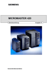
MICROMASTER 420/430/440 Getting Started Guide ޕ䰘ᤷই English Deutsch Français EspaĔol Italiano Warnings, Cautions and Notes The following Warnings, Cautions and Notes are provided for your safety and as a means of preventing damage to the product or components in the machines connected. Specific Warnings, Cautions and Notes that apply to particular activities are listed at the beginning of the relevant sections. Please read the information carefully, since it is provided for your personal safety and will also help prolong the service life of your inverter and the equipment you connect to it. Warnungen, Vorsichtshinweise und Hinweise Die nachstehenden Warnungen, Vorsichtshinweise und Hinweise sind für die Sicherheit des Benutzers vorgesehen sowie als Hilfsmittel, um Schaden an dem Erzeugnis oder an Teilen der angeschlossenen Maschine zu verhindern. Spezifische Warnungen, Vorsichtshinweise und Hinweise, die für bestimmte Tätigkeiten gelten, sind am Anfang der jeweiligen Abschnitte zusammengestellt. Bitte diese Informationen sorgfältig lesen, da sie für Ihre persönliche Sicherheit bestimmt sind und auch eine längere Lebensdauer des Umrichters und der daran angeschlossenen Geräte unterstützen. Avertissements et remarques Les avertissements et remarques figurant dans la suite sont donnés pour assurer la sécurité de l’utilisateur ainsi que pour prévenir des dommages sur le produit ou sur des éléments de la machine raccordée. Les avertissements et remarques spécifiques, applicables à certaines activités, sont regroupés au début du chapitre correspondant. Prière de lire attentivement ces informations car elles sont importantes pour votre sécurité personnelle ainsi que pour assurer une longue durée de vie du variateur ainsi que des appareils raccordés. Advertencias, precauciones y notas Las presentes advertencias, precauciones y notas están pensadas para su seguridad y como medio para prevenir daños en el producto o en componentes situados en las máquinas conectadas. Advertencias, precauciones y notas específicas aplicables en actividades particulares figuran al comienzo de los capítulos o apartados correspondientes. Rogamos leer cuidadosamente la información ya que se entrega para su seguridad personal y le ayudará a prolongar la vida útil de su convertidor y el equipo que conecte al mismo. Avvertenze tecniche di sicurezza La presente guida operativa contiene avvertenze tecniche relative alla sicurezza delle persone ed alla prevenzione dei danni materiali che vanno assolutamente osservate. Le avvertenze, contrassegnate da un triangolo, a seconda del grado di pericolo, sono chiamate Pericolo, Attenzione, Avvertenze e sono di solito riportate all’inizio dei vari capitoli. Si raccomanda di leggere con attenzione le informazioni fornite, in quanto sono state stilate per garantire l’incolumità personale e per contribuire a prolungare la durata di funzionamento sia dell'Inverter sia delle apparecchiature ad esso collegate. MICROMASTER 420/430/440, Getting Started Guide 10/14 - A5E02779537A3 1 ! Warnings ¾ This equipment contains dangerous voltages and controls potentially dangerous rotating mechanical parts. Noncompliance with Warnings or failure to follow the instructions contained in this manual can result in loss of life, severe personal injury or serious damage to property. ¾ Only suitably qualified personnel should work on this equipment, and only after becoming familiar with all safety notices, installation, operation and maintenance procedures contained in this manual. The successful and safe operation of this equipment is dependent upon its proper handling, installation, operation and maintenance. ¾ The DC link of all MICROMASTER modules remains at a hazardous voltage level for 5 minutes after all voltages have been disconnected. Therefore always wait for 5 minutes after disconnecting the inverter from the power supply before carrying out work on any MICROMASTER modules. ¾ This equipment is capable of providing internal motor overload protection in accordance with UL508C section 43. Refer to P0610 (level 3) and P0335. Motor overload protection can also be provided using an external PTC via a digital input. ¾ Integral solid state short circuit protection does not provide branch circuit protection. Branch circuit protection must be provided in accordance with the national and local electrical codes. This drive is intended for connection to single motor circuits only (not suitable for group installation). ¾ This equipment is designed for field installation in an enclosure. ¾ The opening of a branch circuit protective device may be an indication of a fault; to reduce the risk of fire or electrical shock components of the drive must be examined and replaced. ¾ This equipment is suitable for use on a circuit capable of delivering not more than 10 kA (standard) or 100 kA (high) rms symmetrical, 600 V ac maximum or 65 kA (Frame Sizes D to GX) symmetrical amperes (rms), for a maximum voltage of: –MM420 = 230 V / 460 V –MM430 = 460 V –MM440 = 230 V / 460 V / 575 V ¾ When in the case of Frame Size A to C is protected by a J type fuse (for more details see Operating Instructions). In case of Frame Size D to GX when it is protected by R/C JFHR2 line fuses, which are specified in the Operating Instructions . ¾ Class 1 60/75 °C copper wire only. 2 ! Warnungen ¾ Das vorliegende Gerät führt gefährliche Spannungen und steuert umlaufende mechanische Teile, die gegebenenfalls gefährlich sind. Die Missachtung der Warnungen oder das Nichtbefolgen der in dieser Anleitung enthaltenen Anweisungen kann Lebensgefahr, schwere Körperverletzung oder schwerwiegenden Sachschaden bewirken. ¾ An diesen Geräten darf nur geeignetes, qualifiziertes Personal arbeiten, und nur, nachdem es sich mit allen Sicherheitshinweisen, Installations-, Betriebs- und Wartungsanweisungen, die in dieser Anleitung vorhanden sind, vertraut gemacht hat. Der erfolgreiche und gefahrlose Betrieb des Gerätes hängt von seiner ordnungsgemäßen Handhabung, Installation, Bedienung und Wartung ab. ¾ Der Zwischenkreis aller MICROMASTER-Geräte behält nach dem Abtrennen sämtlicher Spannungen 5 Minuten lang eine gefährliche Spannung bei. Deshalb vor dem Durchführen von Arbeiten an einer der MICROMASTER-Baugruppen nach dem Abtrennen des Umrichters von der Stromversorgung 5 Minuten abwarten. ¾ Dieses Gerät kann inneren Motorüberlastungsschutz gemäß UL508C, Abschnitt 43, herstellen. Siehe P0610 (Stufe 3) und P0335. Motorüberlastungsschutz kann auch durch Verwendung eines externen PTC (Kaltleiters) über einen Digitaleingang hergestellt werden. ¾ Der integrierte Halbleiter-Kurzschlussschutz bietet keinen Schutz für Abzweigstromkreise. Der Schutz für Abzweigstromkreise ist gemäß den lokalen Normen und Sicherheitsstandards für Elektroinstallationen vorzusehen. Dieser Antrieb ist ausschließlich für den Anschluss an einzelne Motorschaltungen vorgesehen (nicht geeignet für die Gruppeninstallation). ¾ Dieses Gerät ist für die Installation beim Kunden in einem Gehäuse vorgesehen. ¾ Das Öffnen einer Abzweigschutzeinrichtung kann auf einen Fehler hinweisen; um die Gefahr eines Brands oder elektrischen Schlags zu reduzieren, müssen die Bauteile des Antriebs überprüft und ersetzt werden. ¾ Dieses Gerät eignet sich für den Einsatz in Stromkreisen mit maximal 10 kA (Standard) oder 100 kA (hoch) symmetrisch/Effektivwert, max. 600 V AC oder 65 kA (Baugrößen D bis GX) symmetrisch/Effektivwert mit einer maximalen Spannung von: - MM420 = 230 V / 460 V - MM430 = 460 V - MM440 = 230 V / 460 V / 575 V Baugröße A bis C wird durch eine Sicherung des Typs J abgesichert (nähere Informationen siehe Betriebsanleitung). Baugröße D bis GX wird durch Sicherungen des Typs R/C JFHR2 abgesichert, die in der Betriebsanleitung spezifiziert sind. ¾ Klasse 1 60/75 °C, nur Kupferdraht. ! Attention ¾ Le présent appareil est le siège de tensions dangereuses et pilote des pièces mécaniques rotatives qui peuvent présenter une source de danger. Le non-respect des avertissements ainsi que des consignes de sécurité figurant dans cette notice peuvent entraîner la mort, des blessures graves ou des dommages matériels importants. ¾ Seules des personnes qualifiées sont habilitées à intervenir sur cet appareil, et cela uniquement après qu’elles se soient familiarisées avec toutes les consignes de sécurité, les instructions d’installation, d’exploitation et de maintenance mentionnées dans cette notice. ¾ Le fonctionnement correct et sûr de cet appareil présuppose une manipulation, une installation, une utilisation et une maintenance conformes aux règles de l’art. Sur tous les MICROMASTER, il subsiste une tension élevée dans le circuit intermédiaire pendant les 5 minutes qui suivent la mise hors tension. Après coupure du variateur, il faudra par conséquent attendre le temps nécessaire avant d’intervenir sur les modules du MICROMASTER. ¾ Cet appareil est capable d ‘offrir une protection interne de la surcharge thermique du moteur conforme à UL 508C section 43 . Se reporter à P0610 (Niveau 3) et P0335. La protection de surcharge thermique du moteur peut également être assurée par une sonde CTP montée sur le moteur. ¾ La protection intégrale contre les courts-circuits n'assure pas la protection des circuits terminaux. La protection des circuits terminaux doit être assurée conformément aux codes de l'électricité nationaux et locaux. Cet entraînement est uniquement destiné au raccordement à des circuits monomoteurs (ne convient pas pour une installation groupée). ¾ Cet équipement est conçu pour une installation de terrain dans une enveloppe. ¾ L'ouverture d'un dispositif de protection de circuit terminal peut indiquer la présence d'un défaut. Pour réduire les risques d'incendie ou de choc électrique, les composants de l'entraînement doivent être examinés et remplacés. ¾ Cet équipement convient pour une utilisation sur un circuit capable de fournir un courant ne dépassant pas 10 kA (standard) ou 100 kA (élevé) ampères symétriques efficaces, 600 V CA au maximum ou de 65 kA (tailles D à GX) ampères symétriques efficaces, pour une tension maximale de : - MM420 = 230 V / 460 V - MM430 = 460 V - MM440 = 230 V / 460 V / 575 V ¾ Pour les tailles A à C, s'il est protégé par un fusible de type J (pour plus de détails voir Instructions de service). Pour les tailles D à GX, s'il est protégé par des fusibles de ligne homologués UL JFHR2, tels que spécifiés dans les Instructions de service. ¾ Seulement cable de cuivre Classe 1 60/75 °C. MICROMASTER 420/430/440, Getting Started Guide 10/14 - A5E02779537A3 ! Advertencias ¾ Este equipo incluye piezas bajo tensión peligrosa y controla órganos mecánicos en rotación potencialmente peligrosos. El no respeto de las Advertencias o la no observación de las instrucciones contenidas en esta Guía pueden provocar la muerte, lesiones graves o daños materiales considerables. ¾ En este equipo sólo deberá trabajar personal adecuadamente cualificado y sólo una vez familiarizado con todas las consignas de seguridad, procedimientos de instalación, operación y mantenimiento contenidos en este Manual. El funcionamiento exitoso y seguro de este equipo depende de si ha sido manipulado, instalado, operado y mantenido adecuadamente. ¾ En el circuito intermedio de todos los módulos MICROMASTER permanece un nivel de tensión peligroso durante 5 minutos tras que hayan sido desconectadas todas las tensiones. Por ello, una vez desconectado el convertidor de la fuente de alimentación, esperar 5 minutos antes de efectuar trabajos en cualquier módulo MICROMASTER. ¾ Este equipo suministra internamente la protección contra sobrecarga del motor de acuerdo a la UL508C sección 43. Referirse al P0610 (nivel 3) y P0335. Puede conseguirse también protección contra sobrecargas del motor utilizando una PTC externa a través de una entrada digital. ¾ La protección contra cortocircuitos por semiconductores integral no protege al circuito de derivación. Los circuitos de derivación deben protegerse según los códigos (normativas) y reglamentos del país en cuestión. Este convertidor está concebido solo para la conexión a circuitos monomotor (no es apto para alimentar varios motores). ¾ Este equipo ha sido diseñado para instalación en campo dentro de una envolvente. ¾ La apertura de un dispositivo protector de derivación puede ser síntoma de defecto; los componentes del accionamiento deben examinarse y repararse para reducir el riesgo de choques eléctricos. ¾ Este equipo es apto para su uso en circuitos con una corriente de cortocircuito máxima de 10 kA (estándar) o 100 kA (alta) eficaz simétrica y una tensión máxima de 600 V AC, o 65 kA (tamaños D a GX) simétrica (eficaz) y un tensión máxima de: - MM420 = 230 V / 460 V - MM430 = 460 V - MM440 = 230 V / 460 V / 575 V ¾ Si un equipo de tamaño A a C está protegido con un fusible de tipo J (para más detalles, ver las instrucciones de servicio). Si un equipo de tamaño D a GX está protegido con un fusible de línea de tipo R/C JFHR2 como el que se especifica en las instrucciones de servicio. ¾ Sólo cableado de cobre Clase 1 60/75 ºC. ! Pericolo ¾ La presente apparecchiatura contiene tensioni pericolose e controlla parti meccaniche rotanti potenzialmente pericolose. L'inosservanza delle relative misure di sicurezza può causare la morte, gravi lesioni alle persone e ingenti danni materiali. ¾ Sulla presente apparecchiatura dovrà operare esclusivamente personale appositamente qualificato e solamente dopo che abbia acquisito piena dimestichezza in merito a tutte le informazioni di sicurezza ed alle procedure di installazione, uso e manutenzione riportate in questa guida. Il corretto e sicuro funzionamento della presente apparecchiatura dipende dall'idoneità degli interventi di installazione, uso e manutenzione. ¾ Il circuito intermedio di tutti i moduli MICROMASTER rimane caricato a livelli pericolosi di tensione per 5 minuti dopo aver disattivato tutte le alimentazioni elettriche. Di conseguenza, prima di effettuare qualsiasi intervento sui moduli MICROMASTER, si raccomanda di attendere almeno 5 minuti dopo aver disattivato l’inverter. ¾ Questo apparecchio è in grado di provvedere internamente alla protezione per sovraccarico del motore in accordo con UL508C parte 43. Riferimento a P0610 (livello 3) e P0335. La protezione per sovraccarico del motore può essere realizzata anche usando una PTC esterna tramite ingresso digitale. ¾ La protezione integrale a stato solido contro i circortocircuiti non assicura la protezione del circuito derivato. La protezione del circuito derivato deve avvenire nel rispetto delle normative elettriche nazionali e locali. Questo azionamento è progettato per il collegamento a singoli circuiti motore (non è adatto per installazioni di gruppo). ¾ Questa apparecchiatura è destinata all'installazione sul campo all'interno di un cabinet. ¾ L'apertura di un dispositivo di protezione del circuito derivato può indicare un guasto; per ridurre il rischio di incendio o folgorazione è necessario esaminare i componenti dell'azionamento ed eventualmente sostituirli. ¾ Questa apparecchiatura può funzionare in un circuito che eroghi max. 10 kA rms simmetrici (Standard) o 100 kA (High), AC 600 V max., oppure 65 kA rms simmetrici (grandezze costruttive da D a GX) per una tensione massima di: - MM420 = 230 V / 460 V - MM430 = 460 V - MM440 = 230 V / 460 V / 575 V ¾ Per le grandezze costruttive da A a C la protezione avviene tramite un fusibile tipo J (per ulteriori dettagli vedere le Istruzioni operative). Per le grandezze costruttive da D a GX la protezione è costituita da fusibili di rete R/C JFHR2, specificati nelle Istruzioni operative. ¾ Classe 1 60/75 °C solo filo di rame. MICROMASTER 420/430/440, Getting Started Guide 10/14 - A5E02779537A3 Note Before carrying out any installation and commissioning procedures, you must read all safety instructions and warnings, including all warning labels attached to the equipment. Make sure that the warning labels are kept in a legible condition and ensure missing or damaged labels are replaced. Hinweise Vor der Durchführung von Installations- und Inbetriebnahmearbeiten unbedingt alle Sicherheitsanweisungen und Warnungen bitte sorgfältig lesen, ebenso alle am Gerät angebrachten Warnschilder. Darauf achten, dass Warnschilder in leserlichem Zustand gehalten werden und dafür sorgen, dass fehlende oder beschädigte Schilder gegebenenfalls ausgetauscht werden. Remarques Avant de procéder à l’installation et à la mise en service, il faut lire attentivement les consignes de sécurité et les avertissements ainsi que toutes les marques d’avertissement apposées sur l’appareil. Veillez à maintenir la lisibilité des marques d’avertissement et à remplacer celles qui manquent ou qui ont été dégradées. Notas Antes de efectuar cualquier tipo de trabajo de instalación y puesta en servicio es necesario leer todas las instrucciones y advertencias de seguridad, incluyendo los rótulos de advertencia fijados al equipo. Asegurarse de que dichos rótulos y advertencias sean siempre legibles y tomar las medidas necesarias para sustituir inmediatamente los rótulos perdidos o dañados. Avvertenza Prima di procedere all'installazione ed alla messa in esercizio, è necessario leggere attentamente le istruzioni di sicurezza e le avvertenze, incluse tutte le targhette di avvertimento applicate alle apparecchiature. Accertarsi che le targhette di avvertimento siano conservate in condizioni leggibili e si abbia cura di sostituire le targhette mancanti o danneggiate. 3 Environmental conditions Keep free from dust and dirt! (Degree of protection = IP20) Von Staub und Schmutz fernhalten! (Schutzart IP20) Tenir libre de poussière et saleté (Degrée de protection = IP20) Mantener libre de polvo y suciedad! (Grado de Protección IP20) Tenere a distanza di polvere ed ambiente sporco (grado di protezione IP20)! ᵜ䇮༷ᓄᐕ൘ᰐ⚠ቈ઼ަԆ⊑⢙Ⲵ⧟ຳѝ(䱢ᣔㅹ㓗 = IP20) . Keep away from water, solvents and chemicals! Von Wasser, Lösungsmitteln und Chemikalien fernhalten! Éviter de l’eau, solvants et des produits chimiques ! Evitar agua, disolventes y productos químicos! Utilizzo a distanza di acqua, materiali chimici! ᵜ䇮༷ᗵ享䘌≤,ⓦࡲ઼ॆᆖ⢙䍘 ! Keep within max./min. operating temperatures! (See manual!) Nur im zulässigen Temperaturbereich betreiben! (Siehe Anleitung!) Usage seulement dans la portée de températures autorisée ! (Cfr. Manuel !) Operar a temperaturas de servicio autorizadas! (Ver manual de operación!) Utilizzo solo nelle temperature di servizio specificate (vedi istruzioni d’operazione) ᵜ䇮༷Ⲵ䘀㹼ᓖᗵ享䲀ᇊ൘ަᴰབྷ / ᴰሿݱ䇨㤳തԕ (䈧৲ⴻޣ)! >50ºC >40ºC <-10ºC Ensure correct ventilation/air flow Ausreichende Entlüftung der Geräte im Schaltschrank sicherstellen Assurez une ventilation sufficante de l’appariel. Garantizar ventilación suficiente de los equipos Garantire una ventilazione sufficiente degli apparecchi ᵜ䇮༷䘀㹼ᰦᗵ享؍䇱䏣ཏⲴ䙊仾 / ߧতオ≄⍱䟿. Ensure good earthing/grounding practices for each inverter and the cabinet Stellen Sie eine gute Erdung untereinander und im Schrank sicher Assurez une bonne mise à la terre entre les appariels et dans l’armoire. Garantice una buena puesta a tierra entre equipos y armarios Mettere bene a terra gli apparecchi sia entrambi sia nel quadro elettrico ⺞؍䇮༷㇡փⲴᡰᴹ䇮༷᧕ൠ⛩䜭㜭ᗇࡠ㢟ྭⲴ᧕ൠ. Contact Local Technical Support: LokaleTechnische Unterstützung Contacter le Support Technique Servicio Téchnico en España Supporto tecnico in Italia Please get in touch with the local contact partners for Technical Support in your local Region for questions and advice concerning any of the installation environment and conditions as shown in the drawings above. Bitte fragen Sie ihre lokalen Partner nach technischem Support in ihrer Region, insbesondere wenn es um die Einhaltung und Sicherstellung der oben dargestellten und erforderlichen Betriebsbedingungen geht Veuillez demander votre partner local vers support technique dans votre région, Consulte al soporte técnico local en su zona, especialmente cuando se trate de asegurar el cumplimiento de las condiciones de servicio enunciadas arriba. Per supporto tecnico da mettersi in contatto con gli indirizzi indicati, sopratutto per domande riguardante l’utilizzo sicuro nelle condizioni sopracitate. surtout pour des questions et conseils concernant les conditions functionelles décrit sur cette page. Europe / Africa America Asia / Pacific Rim Tel: +49 (0) 180 5050 222 Tel: +1 423 262 2522 Fax. +1 423 262 2289 E-Mail: [email protected] Tel: + 86 1064 75 75 75 Fax: +49 (0) 180 5050 223 E-Mail: [email protected] 4 Fax. +86 1064 74 74 74 E-Mail [email protected] www.ad.siemens.com.cn www.ad.siemens.com.cn/service Phone: +86-(0)-10-6471-9990 Fax: +86-(0)-10-6471-9991 Email: [email protected] MICROMASTER 420/430/440, Getting Started Guide 10/14 - A5E02779537A3 Dimension Drawings Maßbilder Encombrements Dibujos acotados Disegni qotati Frame Size A Frame Size B Ø 4.8 mm 0.19" 55 mm 2.2" 160 mm 6.30" MM420 MM440 Frame Size D MM430 MM440 Ø 5.5 mm 0.22" Operator Panel MM420 MM440 Ø 17.5 mm 0.68" 204 mm 8.03" 174 mm 6.85" Frame Size E Operator Panel Operator Panel MM420 MM430 MM440 174 mm 6.85" 138 mm 5.43" Ø 4.5 mm 0.17" Ø 17.5 mm 0.68" Frame Size C Frame Size F Operator Panel Operator Panel Ø 15 mm 0.59" 486 mm 19.13" MM430 MM440 616.4 mm 24.27" MM430 MM440 810 mm 31.89" With Filter 1110 mm 43.70" 235 mm 9.25" 235 mm 9.25" 300 mm 11.81" MICROMASTER 420/430/440, Getting Started Guide 10/14 - A5E02779537A3 5 Frame Size FX 356 mm Ø 30 mm14" 1.2" MM430 MM440 Frame Size GX 125 mm 125 mm 4.9" 4.9" Ø 20 mm 0.8" 1321 mm 52 " 12 mm 0.5" MM430 MM440 1376 m 54 " 125 mm 125 mm 4.9" 4.9" 12 mm 0.5" 326 mm 12.8" 125 mm 125 mm 4.9" 4.9" 545 mm 21"" Ø 28 mm 1.1" MM430 MM440 Ø 20 mm 0.8" 1459 mm 57 " MM430 MM440 125 mm 125 mm 4.9" 4.9" 12 mm 0.5" 1506 m 52.3" 12 mm 0.5" 326 mm 12.8" 6 MICROMASTER 420/430/440, Getting Started Guide 10/14 - A5E02779537A3 Connecting Power Terminals Frame Size A Frame Size B, C Leistungsanschlüsse Connexions de puissance Conectores de carga Connessioni 1 2 4 3 5 6 MM430 MM440 L3 L3 L2 L2 L1 L1 U V W MICROMASTER 420/430/440, Getting Started Guide 10/14 - A5E02779537A3 U V W 7 Frame Sizes D, E Frame Size F 1 1 2 2 19 mm AF 3 3 R+ L N L1 L2 DC- B+ L3 DC- DC+ U V PE Ground DC+ W L N L1 L2 L3 U V W Ground PE Ground 8 Ground MICROMASTER 420/430/440, Getting Started Guide 10/14 - A5E02779537A3 Frame Size FX, GX PE W1/L3 V1/L2 U1/L1 PE U2/T1 V2/T2 W2/T3 Motor Motor Moteur Motor Motore PE U V W U V W = Ground MICROMASTER 420/430/440, Getting Started Guide 10/14 - A5E02779537A3 9 Connecting Control Terminals Anschließen der Steuerklemmen Connexions de commande Conectores para líneas de control Connessione die morsetti di comando 10 Motor Frequency Motorfrequenz Fréquence moteur Frecuencia del motor Frequenza motore MICROMASTER 420/430/440, Getting Started Guide 10/14 - A5E02779537A3 MM420 Specifications Frame Size Dimensions A WxHxD B WxHxD C WxHxD mm inch mm inch mm inch 73 x 173 x 149 2.87 x 6.81 x 5.87 149 x 202 x 172 5.87 x 7.95 x 6.77 185 x 245 x 195 7.28 x 9.65 x 7.68 Tightening torque for power connections Nm 1.1 lbf.in 10 Nm 1.5 lbf.in 13.3 Nm 2.25 lbf.in 20 Input voltage range 1 AC 200 V – 240 V, ± 10 % (with built in Class A Filter) Order No. 6SE64202AB112AB122AB132AB152AA1 5AA1 7AA1 5AA1 Fuse [A] 10 10 10 10 Recommended 3NA 3803 3803 3803 3803 For UL specified * * * * [mm2] 1.0 1.0 1.0 1.0 Input Cable, min. [awg] 18 18 18 18 [mm2] 2.5 2.5 2.5 2.5 Input Cable, max. [awg] 14 14 14 14 [mm2] 1.0 1.0 1.0 1.0 Output Cable, min. [awg] 18 18 18 18 [mm2] 2.5 2.5 2.5 2.5 Output Cable, max. [awg] 14 14 14 14 2AB175AA1 16 3805 * 1.0 18 2.5 14 1.0 18 2.5 14 2AB211BA1 20 3807 * 2.5 16 6.0 10 1.0 18 6.0 10 2AB215BA1 20 3807 * 2.5 16 6.0 10 1.0 18 6.0 10 2AB222BA1 32 3812 * 4.0 12 6.0 10 1.0 18 6.0 10 2AB230CA1 40 3817 * 6.0 10 10.0 8 1.5 16 10.0 8 Input voltage range 1 AC 200 V – 240 V, ± 10 % (Unfiltered) Order No. 6SE64202UC112UC122AA1 5AA1 Fuse [A] 10 10 Recommended 3NA 3803 3803 For UL specified * * [mm2] 1.0 1.0 Input Cable, min. [awg] 18 18 [mm2] 2.5 2.5 Input Cable, max. [awg] 14 14 [mm2] 1.0 1.0 Output Cable, min. [awg] 18 18 [mm2] 2.5 2.5 Output Cable, max. [awg] 14 14 2UC175AA1 16 3805 * 1.0 18 2.5 14 1.0 18 2.5 14 2UC211BA1 20 3807 * 1.0 18 6.0 10 1.0 18 6.0 10 2UC215BA1 20 3807 * 1.0 18 6.0 10 1.0 18 6.0 10 2UC222BA1 32 3812 * 1.0 18 6.0 10 1.0 18 6.0 10 2UC230CA1 40 3817 * 2.5 14 10.0 8 1.5 16 10.0 8 2UC137AA1 10 3803 * 1.0 18 2.5 14 1.0 18 2.5 14 2UC155AA1 10 3803 * 1.0 18 2.5 14 1.0 18 2.5 14 Input voltage range 3 AC 200 V – 240 V, ± 10 % (with built in Class A Filter) Order No. 6SE64202AC23 2AC24 2AC25 -0CA1 -0CA1 -5CA1 Fuse [A] 25 32 35 3810 3812 3814 Recommended 3NA For UL specified * * * [mm2] 2.5 2.5 4.0 Input Cable, min. [awg] 14 14 12 [mm2] 10.0 10.0 10.0 Input Cable, max. [awg] 8 8 8 [mm2] 1.5 2.5 4.0 Output Cable, min. [awg] 16 14 12 [mm2] 10.0 10.0 10.0 Output Cable, max. [awg] 8 8 8 *UL listed fuses, such as those stated in the warnings on page 2 are required for use in America. *UL-gelistete Sicherungen, wie in den Warnhinweisen auf Seite 2 angegeben, sind für den Einsatz in Amerika vorgeschrieben. *Des fusibles homologués UL, tels que ceux mentionnés dans les avertissements à la page 2 sont requis pour une utilisation en Amérique. *I fusibili omologati UL, come quelli indicati nelle avvertenze a pagina 2, sono richiesti per l'utilizzo sul territorio americano. *Para uso en Norteamérica se requieren fusibles conformes a UL, como los que figuran en las advertencias de la página 2. MICROMASTER 420/430/440, Getting Started Guide 10/14 - A5E02779537A3 11 Input voltage range 3 AC 200 V – 240 V, ± 10 % (Unfiltered) Order No. 6SE64202UC112UC122AA1 5AA1 Fuse [A] 10 10 Recommended 3NA 3803 3803 For UL specified * * [mm2] 1.0 1.0 Input Cable, min. [awg] 18 18 2 [mm ] 2.5 2.5 Input Cable, max. [awg] 14 14 [mm2] 1.0 1.0 Output Cable, min. [awg] 18 18 [mm2] 2.5 2.5 Output Cable, max. [awg] 14 14 Order No. 6SE6420- Fuse Recommended For UL specified [A] 3NA 2UC137AA1 10 3803 * 1.0 18 2.5 14 1.0 18 2.5 14 2UC155AA1 10 3803 * 1.0 18 2.5 14 1.0 18 2.5 14 2UC232UC242UC250CA1 0CA1 5CA1 25 32 35 3810 3812 3814 * * * [mm2] 2.5 2.5 4.0 Input Cable, min. [awg] 14 14 12 2 [mm ] 10.0 10.0 10.0 Input Cable, max. [awg] 8 8 8 1.5 2.5 4.0 [mm2] Output Cable, min. [awg] 16 14 12 2 [mm ] 10.0 10.0 10.0 Output Cable, max. [awg] 8 8 8 Input voltage range 3 AC 380 V – 480 V, ± 10 % (with built in Class A Filter) Order No. 6SE64202AD222AD232AD242AD252BA1 0BA1 0BA1 5CA1 Fuse [A] 16 16 20 20 Recommended 3NA 3805 3805 3807 3807 For UL specified * * * * [mm2] 1.0 1.0 1.5 2.5 Input Cable, min. [awg] 18 18 16 14 6.0 6.0 6.0 10.0 [mm2] Input Cable, max. [awg] 10 10 10 8 [mm2] 1.0 1.0 1.0 1.5 Output Cable, min. [awg] 18 18 18 16 [mm2] 6.0 6.0 6.0 10.0 Output Cable, max. [awg] 10 10 10 8 12 2UC175AA1 10 3803 * 1.0 18 2.5 14 1.0 18 2.5 14 2AD275CA1 25 3810 * 4.0 12 10.0 8 2.5 14 10.0 8 2UC211BA1 16 3805 * 1.0 18 6.0 10 1.0 18 6.0 10 2UC215BA1 16 3805 * 1.0 18 6.0 10 1.0 18 6.0 10 2UC222BA1 20 3807 * 1.0 18 6.0 10 1.0 18 6.0 10 2AD311CA1 35 3814 * 6.0 10 10.0 8 4.0 12 10.0 8 MICROMASTER 420/430/440, Getting Started Guide 10/14 - A5E02779537A3 Input voltage range 3 AC 380 V – 480 V, ± 10 % (Unfiltered) Order No. 6SE64202UD13 2UD15 -7AA1 -5AA1 Fuse [A] 10 10 Recommended 3NA 3803 3803 For UL specified * * [mm2] 1.0 1.0 Input Cable, min. [awg] 18 18 2 [mm ] 2.5 2.5 Input Cable, max. [awg] 14 14 [mm2] 1.0 1.0 Output Cable, min. [awg] 18 18 [mm2] 2.5 2.5 Output Cable, max. [awg] 14 14 Order No. Fuse Recommended For UL specified Input Cable, min. Input Cable, max. Output Cable, min. Output Cable, max. 6SE6420[A] 3NA [mm2] [awg] [mm2] [awg] [mm2] [awg] [mm2] [awg] 2UD25 -5CA1 20 3807 * 2.5 14 10.0 8 1.5 16 10.0 8 2UD27 -5CA1 25 3810 * 4.0 12 10.0 8 2.5 14 10.0 8 2UD17 -5AA1 10 3803 * 1.0 18 2.5 14 1.0 18 2.5 14 2UD21 -1AA1 10 3803 * 1.0 18 2.5 14 1.0 18 2.5 14 2UD21 -5AA1 10 3803 * 1.0 18 2.5 14 1.0 18 2.5 14 2UD22 -2BA1 16 3805 * 1.0 18 6.0 10 1.0 18 6.0 10 2UD23 -0BA1 16 3805 * 1.0 18 6.0 10 1.0 18 6.0 10 2UD24 -0BA1 20 3807 * 1.5 16 6.0 10 1.0 18 6.0 10 2UD31 -1CA1 35 3814 * 6.0 10 10.0 8 4.0 12 10.0 8 *UL listed fuses, such as those stated in the warnings on page 2 are required for use in America. *UL-gelistete Sicherungen, wie in den Warnhinweisen auf Seite 2 angegeben, sind für den Einsatz in Amerika vorgeschrieben. *Des fusibles homologués UL, tels que ceux mentionnés dans les avertissements à la page 2 sont requis pour une utilisation en Amérique. *I fusibili omologati UL, come quelli indicati nelle avvertenze a pagina 2, sono richiesti per l'utilizzo sul territorio americano. *Para uso en Norteamérica se requieren fusibles conformes a UL, como los que figuran en las advertencias de la página 2. MICROMASTER 420/430/440, Getting Started Guide 10/14 - A5E02779537A3 13 MM430 Specifications Frame Size Dimensions C BxHxT D BxHxT E BxHxT F BxHxT FX BxHxT GX BxHxT mm inch mm inch mm inch mm inch mm inch mm inch 185 u 245 u 195 7,28 u 9,65 u 7,68 275 u 520 u 245 10,82 u 20,47 u 9,65 275 u 650 u 245 10,82 u 25,59 u 9,65 350 u 850 mm u 320 (Height with filter 1150) 13,78 u 33,46 u 12,60 (Height with filter 45,28) 326 u 1400 u 356 12,80 u 55,12 u 12,83 326 u 1533 u 545 12,80 u 60,35 u 21,46 Input voltage range 3 AC 380 V … 480 V, ± 10 % (with built in Class A Filter) Order No. 6SE64302AD27 2AD31 2AD31 2AD31 -5CA0 -1CA0 -5CA0 -8DA0 [A] 20 32 35 50 Recommended Fuse 3NA 3807 3812 3814 3820 [A] 50 Fuses recommended for UL applications 3NE * * * 1817-0 2,5 4,0 6,0 10,0 [mm2] Input Cable Min. [AWG] 14 12 10 8 [mm2] 10,0 10,0 10,0 35,0 Input Cable Max. [AWG] 8 8 8 2 [mm2] 2,5 4,0 6,0 10,0 Output Cable Min. [AWG] 14 12 10 8 2 [mm ] 10,0 10,0 10,0 35,0 Output Cable Max. [AWG] 8 8 8 2 Order No. Recommended Fuse Fuses recommended for UL applications Input Cable Min. Input Cable Max. Output Cable Min. Output Cable Max. 6SE6430[A] 3NA [A] 3NE [mm2] [AWG] [mm2] [AWG] [mm2] [AWG] [mm2] [AWG] 2AD33 -7EA0 100 3830 100 1021-0 25,0 3 35,0 2 25,0 3 35,0 2 2AD34 -5EA0 125 3832 125 1022-0 25,0 3 35,0 2 25,0 3 35,0 2 2AD35 -5FA0 160 3836 160 1224-0 35,0 2 150,0 300 50,0 1/0 150,0 300 2AD37 -5FA0 200 3140 200 1225-0 70,0 2/0 150,0 300 70,0 2/0 150,0 300 Tightening torques for power terminals Nm 2,25 1,7 lbf-ft Nm 10 (max.) 7,4 (max.) lbf-ft Nm 10 (max.) 7,4 (max.) lbf-ft Nm 50 lbf-ft 36,9 Nm 25 lbf-ft 18,4 Nm 25 18,4 lbf-ft 2AD32 -2DA0 63 3822 63 1818-0 10,0 8 35,0 2 10,0 8 35,0 2 2AD33 -0DA0 80 3824 80 1820-0 16,0 6 35,0 2 16,0 6 35,0 2 2AD38 -8FA0 250 3144 250 1227-0 70,0 2/0 150,0 300 95,0 4/0 150,0 300 *UL listed fuses, such as those stated in the warnings on page 2 are required for use in America. *UL-gelistete Sicherungen, wie in den Warnhinweisen auf Seite 2 angegeben, sind für den Einsatz in Amerika vorgeschrieben. *Des fusibles homologués UL, tels que ceux mentionnés dans les avertissements à la page 2 sont requis pour une utilisation en Amérique. *I fusibili omologati UL, come quelli indicati nelle avvertenze a pagina 2, sono richiesti per l'utilizzo sul territorio americano. *Para uso en Norteamérica se requieren fusibles conformes a UL, como los que figuran en las advertencias de la página 2. 14 MICROMASTER 420/430/440, Getting Started Guide 10/14 - A5E02779537A3 Input voltage range 3 AC 380 V … 480 V, ± 10 % (Unfiltered) Order No. 6SE64302UD27 2UD31 -5CA0 -1CA0 [A] 20 32 Recommended Fuse 3NA 3807 3812 [A] Fuses recomnended for UL applications 3NE * * [mm2] 2,5 4,0 Input Cable Min. [AWG] 14 12 [mm2] 10,0 10,0 Input Cable Max. [AWG] 8 8 [mm2] 2,5 4,0 Output Cable Min. [AWG] 14 12 [mm2] 10,0 10,0 Output Cable Max. [AWG] 8 8 Order No. 6SE6430- Recommended Fuse Fuses recomnended for UL applications Input Cable Min. Input Cable Max. Output Cable Min. Output Cable Max. [A] 3NA [A] 3NE [mm2] [AWG] [mm2] [AWG] [mm2] [AWG] [mm2] [AWG] 2UD33 -7EA0 100 3830 100 1021-0 25,0 3 35,0 2 25,0 3 35,0 2 2UD34 -5EA0 125 3832 125 1022-0 25,0 3 35,0 2 25,0 3 35,0 2 2UD31 -5CA0 35 3814 * 6,0 10 10,0 8 6,0 10 10,0 8 2UD31 -8DA0 50 3820 50 1817-0 10,0 8 35,0 2 10,0 8 35,0 2 2UD32 -2DA0 63 3822 63 1818-0 10,0 8 35,0 2 10,0 8 35,0 2 2UD35 -5FA0 160 3836 160 1224-0 35,0 2 150,0 300 35,0 2 150,0 300 2UD37 -5FA0 200 3140 200 1225-0 70,0 2/0 150,0 300 70,0 2/0 150,0 300 2UD38 -8FA0 250 3144 250 1227-0 70,0 2/0 150,0 300 95,0 4/0 150,0 300 2UD33 -0DA0 80 3824 80 1820-0 16,0 6 35,0 2 16,0 6 35,0 2 Input voltage range 3 AC 380 V … 480 V, ± 10 % (Unfiltered) Order No. Recommended Fuse Input Cable Min. Input Cable Max. Output Cable Min. Output Cable Max. Pipe cable shoe to DIN 46235 6SE6430[A] [mm2] [AWG] or [kcmil] [mm2] [AWG] or [kcmil] [mm2] [AWG] or [kcmil] [mm2] [AWG] or [kcmil] [mm] 2UD41-1FA0 250 3NE1227-0 1 x 95 or 2 x 35 2UD41-3FA0 315 3NE1230-0 1 x 150 or 2 x 50 2UD41-6GA0 400 3NE1332-0 1 x 185 or 2 x 70 2UD42-0GA0 450 3NE1333-0 1 x 240 or 2 x 70 2UD42-5GA0 560 3NE1435-0 2 x 95 1 x 4/0 or 2 x 2 1 x 300 or 2 x 1/0 1 x 400 or 2 x 2/0 1 x 500 or 2 x 2/0 2 x 4/0 1 x 185 or 2 x 120 1 x 185 or 2 x 120 2 x 240 2 x 240 2 x 240 1 x 350 or 2 x 4/0 1 x 350 or 2 x 4/0 2 x 400 2 x 400 2 x 400 1 x 95 or 2 x 35 1 x 150 or 2 x 50 1 x 185 or 2 x 70 1 x 240 or 2 x 70 2 x 95 1 x 4/0 or 2 x 2 1 x 300 or 2 x 1/0 1 x 400 or 2 x 2/0 1 x 500 or 2 x 2/0 2 x 4/0 1 x 185 or 2 x 120 1 x 185 or 2 x 120 2 x 240 2 x 240 2 x 240 1 x 350 or 2 x 4/0 1 x 350 or 2 x 4/0 2 x 400 2 x 400 2 x 400 10 10 10 10 10 *UL listed fuses, such as those stated in the warnings on page 2 are required for use in America. *UL-gelistete Sicherungen, wie in den Warnhinweisen auf Seite 2 angegeben, sind für den Einsatz in Amerika vorgeschrieben. *Des fusibles homologués UL, tels que ceux mentionnés dans les avertissements à la page 2 sont requis pour une utilisation en Amérique. *I fusibili omologati UL, come quelli indicati nelle avvertenze a pagina 2, sono richiesti per l'utilizzo sul territorio americano. *Para uso en Norteamérica se requieren fusibles conformes a UL, como los que figuran en las advertencias de la página 2. MICROMASTER 420/430/440, Getting Started Guide 10/14 - A5E02779537A3 15 MM440 Specifications Frame Size Dimensions A WxHxD B WxHxD C WxHxD D WxHxD E WxHxD F WxHxD FX WxHxD GX WxHxD Tightening torque for power connections mm inch mm inch mm inch mm inch mm inch mm inch mm inch mm inch 73 u 173 u 149 2.87 u 6.81 u 5.87 149 u 202 u 172 5.87 u 7.95 u 6.77 185 u 245 u 195 7.28 u 9.65 u 7.68 275 u 520 u 245 10.82 u 20.47 u 9.65 275 u 650 u 245 10.82 u 25.59 u 9.65 350 u 850 Height with filter 1150 13.78 u 33.46 u 12.60 Height with filter 45.28 326 u 1400 u 356 12.80 u 55.12 u 12.83 326 u 1533 u 545 12.80 u 60.35 u 21.46 Nm 1.1 Nm 1.5 Nm 2.25 Nm 10 (max.) Nm 10 (max.) Nm 50 Nm 25 Nm 25 Input voltage range 1 AC 200 V – 240 V, ± 10 % (with built in Class A Filter) Order No. 6SE64402AB11 2AB12 2AB13 2AB15 -2AA1 -5AA1 -7AA1 -5AA1 Fuse [A] 10 10 10 16 Recommended 3NA 3803 3803 3803 3805 for UL specified * * * * [mm2] 1.0 1.0 1.0 1.5 Input Cable Min. [awg] 18 18 18 16 [mm2] 2.5 2.5 2.5 2.5 Input Cable Max. [awg] 14 14 14 14 [mm2] 1.0 1.0 1.0 1.0 Output Cable Min. [awg] 18 18 18 18 [mm2] 2.5 2.5 2.5 2.5 Output Cable Max. [awg] 14 14 14 14 2AB17 -5AA1 16 3805 * 1.5 16 2.5 14 1.0 18 2.5 14 2AB21 -1BA1 20 3807 * 2.5 14 6.0 10 1.0 18 6.0 10 2AB21 -5BA1 20 3807 * 2.5 14 6.0 10 1.0 18 6.0 10 2AB22 -2BA1 32 3812 * 4.0 12 6.0 10 1.0 18 6.0 10 2AB23 -0CA1 40 3817 * 6.0 10 10.0 8 1.5 16 10.0 8 Input voltage range 1 AC 200 V – 240 V. ± 10 % (Unfiltered) Order No. 6SE64402UC11 2UC12 -2AA1 -5AA1 Fuse [A] 10 10 Recommended 3NA 3803 3803 for UL specified * * [mm2] 1.0 1.0 Input Cable Min. [awg] 18 18 [mm2] 2.5 2.5 Input Cable Max. [awg] 14 14 [mm2] 1.0 1.0 Output Cable Min. [awg] 18 18 [mm2] 2.5 2.5 Output Cable Max. [awg] 14 14 2UC17 -5AA1 16 3805 * 1.5 16 2.5 14 1.0 18 2.5 14 2UC21 -1BA1 20 3807 * 2.5 14 6.0 10 1.0 18 6.0 10 2UC21 -5BA1 20 3807 * 2.5 14 6.0 10 1.0 18 6.0 10 2UC22 -2BA1 32 3812 * 4.0 12 6.0 10 1.0 18 6.0 10 2UC23 -0CA1 40 3817 * 6.0 10 10.0 8 1.5 16 10.0 8 2UC13 -7AA1 10 3803 * 1.0 18 2.5 14 1.0 18 2.5 14 2UC15 -5AA1 16 3805 * 1.5 16 2.5 14 1.0 18 2.5 14 *UL listed fuses, such as those stated in the warnings on page 2 are required for use in America. *UL-gelistete Sicherungen, wie in den Warnhinweisen auf Seite 2 angegeben, sind für den Einsatz in Amerika vorgeschrieben. *Des fusibles homologués UL, tels que ceux mentionnés dans les avertissements à la page 2 sont requis pour une utilisation en Amérique. *I fusibili omologati UL, come quelli indicati nelle avvertenze a pagina 2, sono richiesti per l'utilizzo sul territorio americano. *Para uso en Norteamérica se requieren fusibles conformes a UL, como los que figuran en las advertencias de la página 2. 16 MICROMASTER 420/430/440, Getting Started Guide 10/14 - A5E02779537A3 Input voltage range 3 AC 200 V – 240 V. ± 10 % (with built in Class A Filter) Order No. 6SE64402AC23 2AC24 2AC25 -0CA1 -0CA1 -5CA1 Fuse [A] 25 32 35 Recommended 3NA 3810 3812 3814 for UL specified * * * [mm2] 2.5 4.0 4.0 Input Cable Min. [awg] 14 12 12 2 [mm ] 10.0 10.0 10.0 Input Cable Max. [awg] 8 8 8 [mm2] 1.5 4.0 4.0 Output Cable Min. [awg] 16 12 12 [mm2] 10.0 10.0 10.0 Output Cable Max. [awg] 8 8 8 Input voltage range 3 AC 200 V – 240 V. ± 10 % (Unfiltered) Order No. 6SE64402UC11 2UC12 2UC13 -2AA1 -5AA1 -7AA1 Fuse [A] 10 10 10 Recommended 3NA 3803 3803 3803 for UL specified * * * [mm2] 1.0 1.0 1.0 Input Cable Min. [awg] 18 18 18 2 [mm ] 2.5 2.5 2.5 Input Cable Max. [awg] 14 14 14 [mm2] 1.0 1.0 1.0 Output Cable Min. [awg] 18 18 18 [mm2] 2.5 2.5 2.5 Output Cable Max. [awg] 14 14 14 2UC15 -5AA1 16 3805 * 1.5 16 2.5 14 1.0 18 2.5 14 2UC17 -5AA1 16 3805 * 1.5 16 2.5 14 1.0 18 2.5 14 2UC21 -1BA1 20 3807 * 2.5 14 6.0 10 1.0 18 6.0 10 2UC21 -5BA1 20 3807 * 2.5 14 6.0 10 1.0 18 6.0 10 2UC22 -2BA1 25 3810 * 2.5 14 6.0 10 1.0 18 6.0 10 2UC23 -0CA1 25 3810 * 4.0 12 10.0 8 1.5 16 10.0 8 2UC24 2UC25 2UC27 2UC31 -0CA1 -5CA1 -5DA1 -1DA1 [A] 32 35 50 80 3NA 3812 3814 3820 3824 3NE * * 1817-0 1820-0 [mm2] 4.0 4.0 10.0 16.0 Input Cable Min. [awg] 12 12 8 6 [mm2] 10.0 10.0 35.0 35.0 Input Cable Max. [awg] 8 8 2 2 [mm2] 4.0 4.0 10.0 16.0 Output Cable Min. [awg] 12 12 8 6 2 [mm ] 10.0 10.0 35.0 35.0 Output Cable Max. [awg] 8 8 2 2 Input voltage range 3 AC 380 V – 480 V. ± 10 % (with built in Class A Filter) Order No. 6SE64402AD22 2AD23 2AD24 2AD25 -2BA1 -0BA1 -0BA1 -5CA1 Fuse [A] 16 16 20 20 Recommended 3NA 3805 3805 3807 3807 for UL specified 3NE * * * * [mm2] 1.5 1.5 2.5 2.5 Input Cable Min. [awg] 16 16 14 14 [mm2] 6.0 6.0 6.0 10.0 Input Cable Max. [awg] 10 10 10 8 [mm2] 1.0 1.0 1.0 2.5 Output Cable Min. [awg] 18 18 18 14 [mm2] 6.0 6.0 6.0 10.0 Output Cable Max. [awg] 10 10 10 8 2UC31 -5DA1 80 3824 1820-0 16.0 6 35.0 2 16.0 6 35.0 2 2UC31 -8EA1 100 3830 1021-0 25.0 3 35.0 2 25.0 3 35.0 2 2UC32 -2EA1 125 3832 1022-0 25.0 3 35.0 2 25.0 3 35.0 2 2UC33 -0FA1 200 3140 1225-0 70.0 2/0 150.0 300 50.0 1/0 150.0 300 2UC33 -7FA1 224/200 3142 1225-0 70.0 2/0 150.0 300 70.0 2/0 150.0 300 2AD27 -5CA1 32 3812 * 4.0 12 10.0 8 4.0 12 10.0 8 2AD31 -1CA1 35 3814 * 6.0 10 10.0 8 6.0 10 10.0 8 2AD31 -5DA1 50 3820 1817-0 10.0 8 35.0 2 10.0 8 35.0 2 Order No. Fuse Recommended for UL specified 6SE6440- MICROMASTER 420/430/440, Getting Started Guide 10/14 - A5E02779537A3 2UC34 -5FA1 250 3144 1227-0 95.0 3/0 150.0 300 95.0 3/0 150.0 300 17 Order No. 6SE6440- 2AD31 2AD32 2AD33 -8DA1 -2DA1 -0EA1 [A] 63 80 100 3NA 3822 3824 3830 3NE 1818-0 1820-0 1021-0 [mm2] 10.0 16.0 25.0 Input Cable Min. [awg] 8 6 3 2 [mm ] 35.0 35.0 35.0 Input Cable Max. [awg] 2 2 2 [mm2] 10.0 16.0 25.0 Output Cable Min. [awg] 8 6 3 2 [mm ] 35.0 35.0 35.0 Output Cable Max. [awg] 2 2 2 Input voltage range 3 AC 380 V – 480 V. ± 10 % (Unfiltered) Order No. 6SE64402UD13 2UD15 2UD17 -7AA1 -5AA1 -5AA1 Fuse [A] 10 10 10 Recommended 3NA 3803 3803 3803 for UL specified * * * [mm2] 1.0 1.0 1.0 Input Cable Min. [awg] 18 18 18 2 [mm ] 2.5 2.5 2.5 Input Cable Max. [awg] 14 14 14 [mm2] 1.0 1.0 1.0 Output Cable Min. [awg] 18 18 18 [mm2] 2.5 2.5 2.5 Output Cable Max. [awg] 14 14 14 Fuse Recommended for UL specified Order No. 6SE6440- 2UD31 -1CA1 [A] 35 3NA 3814 3NE * [mm2] 6.0 Input Cable Min. [awg] 10 [mm2] 10.0 Input Cable Max. [awg] 8 [mm2] 6.0 Output Cable Min. [awg] 10 [mm2] 10.0 Output Cable Max. [awg] 8 Input voltage range 3 AC 380 V – 480 V ± 10 % Order No. 6SE6440[A] Recommended Fuse 3NE Pipe cable shoe to [mm] DIN 46235 Fuse Recommended for UL specified Input Cable Min. Input Cable Max. Output Cable Min. Output Cable Max. 18 [mm2] [awg] or [kcmil] [mm2] [awg] or [kcmil] [mm2] [awg] or [kcmil] [mm2] [awg] or [kcmil] 2AD33 -7EA1 125 3832 1022-0 25.0 3 35.0 2 25.0 3 35.0 2 2UD21 -1AA1 10 3803 * 1.0 18 2.5 14 1.0 18 2.5 14 2AD34 -5FA1 160 3836 1224-0 35.0 2 150.0 300 50.0 1/0 150.0 300 2UD21 -5AA1 10 3803 * 1.0 18 2.5 14 1.0 18 2.5 14 2AD35 -5FA1 200 3140 1225-0 70.0 2/0 150.0 300 70.0 2/0 150.0 300 2AD37 -5FA1 250 3144 1227-0 95.0 3/0 150.0 300 95.0 3/0 150.0 300 2UD22 -2BA1 16 3805 * 1.5 16 6.0 10 1.0 18 6.0 10 2UD31 2UD31 2UD32 2UD33 2UD33 -5DA1 -8DA1 -2DA1 -0EA1 -7EA1 50 63 80 100 125 3820 3822 3824 3830 3832 1817-0 1818-0 1820-0 1021-0 1022-0 10.0 10.0 16.0 25.0 25.0 8 8 6 3 3 35.0 35.0 35.0 35.0 35.0 2 2 2 2 2 10.0 10.0 16.0 25.0 25.0 8 8 6 3 3 35.0 35.0 35.0 35.0 35.0 2 2 2 2 2 (Unfiltered) 2UD38-8FA1 2UD41-1FA1 2UD41-3GA1 250 315 400 1227-0 1230-0 1332-0 2UD23 -0BA1 16 3805 * 1.5 16 6.0 10 1.0 18 6.0 10 2UD24 -0BA1 20 3807 * 2.5 14 6.0 10 1.0 18 6.0 10 2UD25 -5CA1 20 3807 * 2.5 14 10.0 8 2.5 14 10.0 8 2UD34 -5FA1 160 3836 1224-0 35.0 2 150.0 300 35.0 2 150.0 300 2UD35 -5FA1 200 3140 1225-0 70.0 2/0 150.0 300 70.0 2/0 150.0 300 2UD37 -5FA1 250 3144 1227-0 95.0 3/0 150.0 300 95.0 3/0 150.0 300 2UD41-6GA1 450 1333-0 2UD27 -5CA1 32 3812 * 4.0 12 10.0 8 4.0 12 10.0 8 2UD42-0GA1 560 1435-0 10 10 10 10 10 1 x 95 or 2 x 35 1 x 4/0 or 2 x 2 1 x 185 or 2 x 120 1 x 350 or 2 x 4/0 1 x 95 or 2 x 35 1 x 4/0 or 2 x 2 1 x 185 or 2 x 120 1 x 350 or 2 x 4/0 1 x 150 or 2 x 50 1 x 300 or 2 x 1/0 1 x 185 or 2 x 120 1 x 350 or 2 x 4/0 1 x 150 or 2 x 50 1 x 300 or 2 x 1/0 1 x 185 or 2 x 120 1 x 350 or 2 x 4/0 1 x 185 or 2 x 70 1 x 400 or 2 x 2/0 2 x 240 2 x 400 1 x 185 or 2 x 70 1 x 400 or 2 x 2/0 2 x 240 2 x 400 1 x 240 or 2 x 70 1 x 500 or 2 x 2/0 2 x 240 2 x 400 1 x 240 or 2 x 70 1 x 500 or 2 x 2/0 2 x 240 2 x 400 2 x 95 2 x 4/0 2 x 240 2 x 400 2 x 95 2 x 4/0 2 x 240 2 x 400 MICROMASTER 420/430/440, Getting Started Guide 10/14 - A5E02779537A3 Input voltage range 3 AC 500 V – 600 V ± 10 % (Unfiltered) Order No. 6SE64402UE17 2UE21 -5CA1 -5CA1 Fuse [A] 10 10 Recommended 3NA 3803-6 3803-6 for UL specified 3NE * * [mm2] 1.0 1.0 Input Cable Min. [awg] 18 18 2 [mm ] 10.0 10.0 Input Cable Max. [awg] 8 8 [mm2] 1.0 1.0 Output Cable Min. [awg] 18 18 [mm2] 10.0 10.0 Output Cable Max. [awg] 8 8 Order No. Fuse Recommended for UL specified Input Cable Min. Input Cable Max. Output Cable Min. Output Cable Max. 6SE6440[A] 3NA 3NE [mm2] [awg] [mm2] [awg] [mm2] [awg] [mm2] [awg] 2UE31 -8DA1 50 3820-6 1817-0 10.0 8 35.0 2 6.0 10 35.0 2 2UE32 -2DA1 63 3822-6 1818-0 10.0 8 35.0 2 10.0 8 35.0 2 2UE22 -2CA1 10 3803-6 * 1.0 18 10.0 8 1.0 18 10.0 8 2UE33 -0EA1 80 3824-6 1820-0 16.0 6 35.0 2 16.0 6 35.0 2 2UE24 -0CA1 16 3805-6 * 1.5 16 10.0 8 1.0 18 10.0 8 2UE33 -7EA1 80 3824-6 1820-0 25.0 3 35.0 2 16.0 6 35.0 2 2UE25 -5CA1 16 3805-6 * 1.5 16 10.0 8 1.0 18 10.0 8 2UE34 -5FA1 125 3132-6 1022-0 25.0 3 150.0 300 25.0 3 150.0 300 2UE27 -5CA1 25 3810-6 * 2.5 14 10.0 8 2.5 14 10.0 8 2UE35 -5FA1 160 3136-6 1224-0 50.0 1/0 150.0 300 35.0 2 150.0 300 2UE31 -1CA1 32 3812-6 * 4.0 12 10.0 8 4.0 12 10.0 8 2UE31 -5DA1 35 3814-6 1803-0 6.0 10 35.0 2 4.0 12 35.0 2 2UE37 -5FA1 160 3136-6 1224-0 50.0 1/0 150.0 300 50.0 1/0 150.0 300 *UL listed fuses, such as those stated in the warnings on page 2 are required for use in America. *UL-gelistete Sicherungen, wie in den Warnhinweisen auf Seite 2 angegeben, sind für den Einsatz in Amerika vorgeschrieben. *Des fusibles homologués UL, tels que ceux mentionnés dans les avertissements à la page 2 sont requis pour une utilisation en Amérique. *I fusibili omologati UL, come quelli indicati nelle avvertenze a pagina 2, sono richiesti per l'utilizzo sul territorio americano. *Para uso en Norteamérica se requieren fusibles conformes a UL, como los que figuran en las advertencias de la página 2. MICROMASTER 420/430/440, Getting Started Guide 10/14 - A5E02779537A3 19 Use of the RS485 Bus Terminator Fig. 1 Fig. 2 Using MICROMASTER 420/430/440 with RS485 communication requires a proper termination at both ends of the bus (between P+ and N-), and correct pull up/ pull down resistors at at least one end of the bus (e.g. from P+ to P10, and N- to 0V). ŹWhen the MICROMASTER drive inverter is the last slave on the bus (Fig 2 on the right), and there are no other pull up/pull down resistors on the bus, the supplied terminator must be connected shown in Fig.1. Ź When the MICROMASTER is the first slave on the bus (Fig. 2) the RS485 Terminator may be used to terminate the bus by using P+ and N- only, for the bus is powered by the last drive as explained. Note: The supply for the pull up/ pull down resistors must be available whenever RS485 communication is in progress! Further information is available in FAQ : ID 12462284 of the Siemens Drive Support in the Net: http://support.automation.siemens.com (type 12462284 in the search box). Der Einsatz des MICROMASTER 420/430/440 in einer RS485-Bus-Kommunikation erfordert 1. eine Stromversorgung und 2. an beiden Bus-Enden einen Abschlusswiderstand zwischen P+ und N-). Ź Ist der Umrichter der letzte Slave auf dem Bus (im Bild 2), so ist dort P+ und N- des beiliegenden RS485 Terminators mit den RS485 Klemmen wie gezeigt (Bild 1) zu verbinden. P10 und 0V können zur Stromversorgung mit Klemme 1 und 2 verbunden werden. Ź Ist der Umrichter der erste Slave (Bild 2, links), so braucht man dort nur den Bus mit P+ N- zu terminieren. Zu beachten: Die Stromversorgung mittels Pull-Up-/Pull-down-Widerständen muss immer zur Verfügung stehen, wenn die RS485 Kommunikation läuft! Weitere Informationen finden Sie in der FAQ Nr. (ID) 12462284 vom Siemens Drive Support unter http://support.automation.siemens.com 20 MICROMASTER 420/430/440, Getting Started Guide 10/14 - A5E02779537A3 L’utilisation des MICROMASTER 420/430/440 dans un réseau de communication RS485 exige : 1. Une alimentation de courant et 2. À chaque terminaison de réseau une résistance entre P+ et N-). Ź Si le convertisseur est le dernier esclave du réseau (Image 2), il faut connecter P+ et N- du „RS485 terminator“ avec les bornes RS485 (voyez image 1). P10 et 0V peuvent être connecté avec les bornes 1 et 2 pour obtenir une alimentation Ź Si le convertisseur est le premier esclave du réseau . (image 2, la gauche), il ne faut que terminer le réseau avec P+ N-. Attention : L’alimentation avec des résistances pull-up / pull-down doit toujours être disponible quand la communication RS485 fonctionne. Vous trouvez des informations supplémentaires sous le „FAQ numéro 12462284“ de Siemens Drive Support : http://support.automation.siemens.com Comunicando en un bus RS485 requiere una terminación apropiada en ambos extremos del bus (entre P + y N-), y unas resistencias pull up/ pull down adecuadas al menos en un extremo del bus (por ejemplo de P + a P10, y de N- a 0V). Ź Cuando el MICROMASTER es el último esclavo del bus (Fig. 2), y no hay ninguna resistencia pull up/ pull down en el bus, el terminador debe conectarse tal y como se muestra en la Fig. 1. Ź Cuando el MICROMASTER es el primer esclavo del bus (Fig. 2) el terminador RS485 se usa para terminar el bus conectando sólo P+ y N-, ya que el bus es alimentado por el último convertidor. Nota: ¡Las resistencias pull up/ pull down deben alimentarse siempre que la comunicación RS485 esté en el progreso! Para más información consulte el FAQ Nr. (ID) 12462284 en la página del Customer Support de Siemens en la red: http://support.automation.siemens.com Il collegamento dei MICROMASTER 420/430/440 attraverso una connessione RS485 richiede una opportuna terminazione del bus ad entrambe le estremitá (fra P+ e N-) e le corrette resistenze di pull up/down almeno ad una estremitá del bus ( p.e. da P+ e P10 e fra N- e 0V). ŹQuando il MICROMASTER é l´ultimo slave sul bus (fig. 2), e non ci sono altre resistenze di pull up/down, i terminatori forniti devonoessere collegati come in fig. 1. ŹQuando il MICROMASTER é il primo slave sul bus (fig. 2), il terminatore deve essere usato solo per connettere P+ e NNota: Quando la comunicazione é attiva, l´alimentazione per le resistenze di pull up/down deve essere sempre presente. Ulteriori informazioni sono disponibili nella FAQ ID 12462284 sul sito Support: http://support.automation.siemens.com ֯⭘ MICROMASTER 420/430/440 ਈ仁ಘⲴRS485 Ѣ㹼䙊䇟ᰦ, ᗵ享൘ ᙫ㓯ᵛㄟⲴєњㄟᆀ(P+઼N-) ѻ䰤䘎᧕ᓄⲴ㓸ㄟ⭥䱫,㘼ф㠣ቁ ᓄ൘ᙫ 㓯Ⲵаㄟᆹ㻵䘲ᖃⲴк / л⭥䱫(ֻྲ, P+оP10(+10V)ѻ䰤,N-о0V ѻ䰤). i ྲ᷌MICROMASTERਈ仁ಘᱟᙫ㓯кⲴᴰਾањӾㄉ(ྲമ2ѝਣ䶒Ⲵаਠਈ仁ಘ),㘼фᙫ㓯к⋑ᴹަԆⲴк/л⭥䱫ᰦ,㓸ㄟಘᗵ 享᤹➗മ1ᡰ⽪Ⲵᯩ⌅䘋㹼䘎᧕. i ྲ᷌MICROMASTERਈ仁ಘᱟᙫ㓯кⲴㅜањӾㄉ(ྲമ2ѝᐖ䶒Ⲵаਠਈ仁ಘ)ᰦ, RS485ⲴєњㄟᆀਟԕѪᙫ㓯Ⲵ㓸ㄟ, ਚ֯⭘ P+ ઼N-, ޣҾᙫ㓯⭡ᴰਾ аਠਈ仁ಘⲴ⭥ᛵߥ, 䈧৲ⴻк䶒Ⲵ䈤᰾. 䈤᰾:ᰐ䇪RS485ᱟ൘䘋㹼䙊䇟, к/л⭥䱫Ⲵ⭥Ⓚ䜭ᱟᗵ享᧕䙊Ⲵ,䈖 㓶Ⲵ䈤᰾䍴ᯉ䈧৲ⴻFAQ ID 12462284, 㾯䰘ᆀޜਨՐࣘ㻵㖞Ⲵ ᇒᡧ᭟ᤱ 䍴ᯉ. 㖁൰: http://support.automation.siemens.com MICROMASTER 420/430/440, Getting Started Guide 10/14 - A5E02779537A3 21 English Deutsch Français EspaĔol Italiano 22 Commissioning The MICROMASTER comes with a Status Display Panel (SDP) and default parameters settings to cover the following: ¾ Motor rating data; voltage, current and frequency are all compatible with the inverter data ¾ Linear V/f motor speed, controlled by an analog potentiometer ¾ Maximum speed 3000 rpm with 50 Hz (3600 rpm with 60 Hz); controllable using a potentiometer via the inverter’s analogue inputs ¾ Ramp-up time / Ramp-down time = 10 s Inbetriebnahme Der MICROMASTER wird mit einem Zustands-Anzeigefeld (Status Display Panel, SDP) und mit Parametereinstellungen geliefert, die folgende Anforderungen abdecken: ¾ Die Motordaten, Spannung, Strom und Frequenz sind sämtlich mit den Daten des Umrichters kompatibel ¾ Lineare U/f-Kennlinie für Motordrehzahl, durch ein analoges Potentiometer gesteuert ¾ Höchstdrehzahl 3000/min bei 50 Hz (3600/min bei 60 Hz); steuerbar über ein an die Analogeingänge des Umrichters angeschlossenes Potentiometer ¾ Rampenhochlaufzeit / Rampenrücklaufzeit = 10 s Mise en service Le MICROMASTER est fourni avec un panneau d’affichage SDP et avec un préréglage des paramètres couvrant les exigences suivantes : ¾ Les caractéristiques nominales du moteur, la tension, le courant et la fréquence sont compatibles avec les caractéristiques du variateur ¾ Caractéristique linéaire de vitesse U/f avec commande par potentiomètre ¾ Vitesse maximale 3000 tr/min à 50 Hz (3600 tr/min à 60 Hz) ; regable par un potentiomètre raccordé à une entrée analogique du variateur ¾ Temps de montée et temps de descente de 10 s Puesta en servico El MICROMASTER se entrega equipado con un panel SDP (Status Display Panel) y parámetros ajustados por defecto que cubren los requisitos siguientes: ¾ Los datos nominales del motor – tensión, corriente y frecuencia – son todos compatibles con los datos del convertidor ¾ Característica V/f lineal de variación de velocidad en el motor, controlada por un potenciómetro analógico ¾ Velocidad máxima 3000/min con 50 Hz (3600/min con 60 Hz), controlable con un potenciómetro a través de las entradas analógicas del convertidor ¾ Tiempo de aceleración / tiempo de deceleración = 10 s Messa in servizio L MICROMASTER è fornito con un display (Status Display Panel) per la visualizzazione e l’impostazione di parametri di default con il quale si può verificare: ¾ Compatibilità dei dati di targa del motore, della tensione, della corrente e della frequenza ai dati dell'inverter ¾ Velocità lineare V/f del motore controllata da un potenziometro analogico ¾ Velocità massima di 3000/min a 50 Hz (3600/min a 60 Hz); controllabile tramite potenziometro attraverso gli ingressi analogici dell'inverter ¾ Tempo di accelerazione / Tempo di decelerazione = 10 s MICROMASTER 420/430/440, Getting Started Guide 10/14 - A5E02779537A3 Additional documentation support On-line documentation All Standard Drives documentation is available on-line at the following site: http://support.automation.siemens.com All documents are available for download, including Operating Instructions and Parameter Lists. Device description files (GSD) The device description files (GSD) are used to integrated an Inverter into a higher level control device, for example, SIMATIC S7. The required GSD files can be downloaded from the internet at the following site: http://support.automation.siemens.com Commissioning file for DeviceNet (EDS file) EDS file for the DeviceNet module for the MICROMASTER 420, 430 and 440. This is required to operate the MICROMASTER 4 via DeviceNet and to allow the configuration tools to recognise the inverter. The required EDS files can be downloaded from the internet at the following site: http://support.automation.siemens.com Zusätzlicher Dokumentations Support On-line Dokumentation Die gesamte Standard Drive Dokumentationen sind On-line auf der folgender Webseite verfügbar: http://support.automation.siemens.com Alle Dokumente können heruntergeladen werden, inbegriffen sind Bedienungsanleitungen und Parameterlisten. Generic Station Description Dateien (GSD) Die Generic Station Description Dateien (GSD) werden benützt, um einen Frequenzumrichter an eine übergeordnerte Steuerung einzubinden, zum Beispiel SIMATIC Step7. Die erforderlichen GSD Dateien können von der folgenden Webseite heruntergelanden werden. http://support.automation.siemens.com Projektierungsdatei für DeviceNet (EDS Datei) EDS Datei für die DeviceNet-Baugruppe für die MICROMASTER-Geräte 420, 430 und 440. Diese wird benötigt, um den MICROMASTER 4 als Teilnehmer am DeviceNet zu betreiben und das Gerät dem Projektierungstools bekannt zumachen. Die erforderlichen EDS Dateien können von der folgenden Webseite heruntergelanden werden. http://support.automation.siemens.com MICROMASTER 420/430/440, Getting Started Guide 10/14 - A5E02779537A3 23 English Deutsch P0010 1 = Quick Commissioning Start Quick Commissioning P0010 must always be set back to ‘0’ before operating the motor. However if P3900 = 1 is set after commissioning this is done automatically Start Schnellinbetriebnahme P0010 muss vor der Betrieb des Motors auf ‘0’ zurückgesetzt werden. Wird nach der Inbetriebnahme P3900 = 1 eingestellt, dann erfolgt dies automatisch. P0100 0 = kW / 50 Hz 1 = hp / 60 Hz 2 = kW / 60 Hz Operation for Europe / N. America For setting 0 and 1 use DIP Switch 2. For setting 2 use P0100 Betrieb für Europa / Nordamerika Die Einstellungen 0 und 1 sind über DIP-Schalter 2 herzustellen. Einstellung 2 über P0100 P0304 10 V - 2000 V Rated Motor Voltage Nominal motor voltage (V) from rating plate Motornennspannung Motornennspannung (V) vom Typenschild des Motors P0305 0 ... 2 * Inom Rated Motor Current Nominal motor current (A) from rating plate Motornennstrom Inom = Motornennstrom (A) vom Typenschild P0307 Rated Motor Power 0 kW - 2000 kW Nominal motor power (kW) from rating plate. If P0100 = 1, values will be in hp P0310 12 Hz - 650 Hz 24 Rated Motor Frequency Nominal motor frequency (Hz) from rating plate Motornennleistung Motornennleistung (kW) vom Typenschild. Bei P0100 = 1, sind die Werte in hp Motornennfrequenz Motornennfrequenz (Hz) vom Typenschild MICROMASTER 420/430/440, Getting Started Guide 10/14 - A5E02779537A3 Français EspaĔol Italiano Mise en service rapide A noter qu’avant la mise en service du moteur, P0010 doit toujours être réglé sur ‘0’. Ceci s’effectue automatiquement si P3900 = 1 après la mise en service Puesta en servicio rápida Recuerde que P0010 debe retornarse siempre a ‘0’ antes de poner en marcha el motor. Sin embargo, si tras la puesta en servicio se ajusta P3900 = 1, esto se hace automáticamente Avvio messa in servizio rapida Si tenga presente che il parametro P0010 deve sempre essere riportato a ‘0’ prima di azionare il motore. Tuttavia, se dopo la messa in servizio il parametro P3900 viene impostato a 1, questa operazione verrà eseguita automaticamente. Exploitation en Europe / Amérique du Nord Pour les réglages 0 et 1, utiliser l'interrupteur DIP 2 Le réglage 2 s'établit par le par. P0100. Europa / Norteamérica Para los ajustes 0 y 1, use interruptor DIP 2 Para el ajuste 2, use P0100 Funzionamento per Europa / N. America Impostare 0 e 1 mediante DIP Switch 2. Impostare 2 mediante P0100 Tension nom. du moteur Tension nominale du moteur (V) relevée sur la plaque signalétique Tensión nom. del motor Tensión nominal del motor (V) tomada de la placa de características Tensione nominale motore Tensione nominale del motore (V) ricavata dai dati di targa caratteristici. Courant nom. du moteur Courant nominal du moteur (A) relevé sur la plaque signalétique Corriente nom. del motor Corriente nominal del motor (A) tomada de la placa de características Corrente nominale motore Corrente nominale del motore (A) ricavata dai dati di targa caratteristici. Puissance nom. moteur Puissance nom. du moteur (kW) relevée sur la plaque signalétique. Pour P0100 = 1, valeurs en hp Potencia nom. del motor Potencia nominal del motor (kW) tomada de la placa de características. Si P0100 = 1, los valores deberán ser en hp Potenza nominale motore Potenza nominale del motore (kW) ricavata dai dati di targa caratteristici. Se il parametro P0100 = 1, i valori saranno in hp. Fréquence nom. moteur Fréquence nominale du moteur (Hz) relevée sur la plaque signalétique Frecuencia nominal del motor Frecuencia nominal del motor (Hz) tomada de la placa de características Frequenza nominale motore Frequenza nominale del motore (Hz) ricavata dai dati di targa caratteristici. MICROMASTER 420/430/440, Getting Started Guide 10/14 - A5E02779537A3 25 English Deutsch P0311 0 - 40000 1/min Rated Motor Speed Nominal motor speed (rpm) from rating plate Motornenndrehzahl Motornenndrehzahl (1/min) vom Typenschild P0700 Selection of Command Source (on / off / reverse) 1 = BOP 2 = Terminal / Digital Inputs (default) Wahl von Befehlsquellen (EIN / AUS / Richtungsumkehr) 1 = BOP 2 = Klemmen (Werkseinstellung) P1000 Selection of Frequency Setpoint 1 = BOP 2 = Analogue Setpoint (default) Wahl des Frequenzsollwerts 1 = BOP 2 = Analogsollwert (Werkseinstellung) P1080 Min. Motor Frequency Sets minimum motor frequency (0 - 650 Hz) at which the motor will run irrespective of the frequency setpoint. The value set here is valid for both clockwise and anticlockwise rotation Minimal Motorfrequenz Stellt die minimale Motorfrequenz (0 - 650 Hz) ein, mit der der Motor unabhängig vom Frequenzsollwert läuft. Der hier eingestellte Wert gilt für beide Drehrichtungen P1082 Max. Motor Frequency Sets maximum motor frequency (0 - 650 Hz) at which the motor will run at irrespective of the frequency setpoint. The value set here is valid for both clockwise and anti-clockwise rotation. Maximal Motorfrequenz Stellt die höchste Motorfrequenz (0 - 650 Hz) ein, mit der der Motor unabhängig vom Frequenzsollwert läuft. Der hier eingestellte Wert gilt für beide Drehrichtungen. Now limited to 550 Hz, see FAQ 101935922. Jetzt auf 550 Hz begrenzt, siehe FAQ 101935922. 26 MICROMASTER 420/430/440, Getting Started Guide 10/14 - A5E02779537A3 Français EspaĔol Italiano Vitesse nom. du moteur Vitesse nominale du moteur (tr/min) relevée sur la plaque signalétique Velocidad nominal del motor Velocidad nominal del motor (rpm) tomada de la placa de características Velocità nominale motore Velocità nominale del motore (giri/minuto) ricavata dai dati di targa del motore. Sélection de la source de commande (marche/arrêt/inversion de sens) 1 = BOP 2 = bornes (réglage usine) Selección de la fuente de órdenes (on / off / inverso) 1 = BOP 2 = Bornes/terminales (Ajuste de fábrica) Selezione della sorgente di comando (on / off / inversione) 1 = BOP 2 = Terminale (Default) Sélection de la consigne de fréquence 1 = BOP 2 = consigne analogique (réglage usine) Selección de la consigna de frecuencia 1 = BOP 2 = Consigna analógica (Ajuste de fábrica) Selezione del valore di riferimento frequenza 1 = BOP 2 = Valore di riferimento analogico (Default) Fréquence moteur min. Réglage de la fréquence minimale du moteur (0 - 650 Hz) indépendamment de la consigne de fréquence. Cette valeur est valable pour les deux sens de rotation. Frecuencia mín. del motor Ajuste del mínimo de la frecuencia del motor (0 - 650 Hz) a partir de la cual girará el motor con indiferencia de la consigna de frecuencia ajustada. El valor aquí ajustado es válido tanto para giro horario (a derechas) como antihorario (a izquierdas) Frequenza min. motore Imposta la frequenza minima (0 - 650 Hz) di funzionamento del motore, indipendentemente dal valore di riferimento frequenza. Il valore qui impostato è valido per il senso di rotazione sia orario sia antiorario. Fréquence moteur max. Réglage de la fréquence maximale du moteur (0 - 650 Hz) indépendamment de la consigne de fréquence. Cette valeur est valable pour les deux sens de rotation. Maintenant limitée à 550Hz , voir FAQ 101935922. Frec. máx. del motor Frequenza max. motore Ajuste del máximo de la frec. del motor (0 - 650 Hz) a partir de la cual girará el motor con indiferencia de la consigna de frec. ajustada. El valor aquí ajustado es válido tanto para giro horario como antihorario. Ahora limitado a 550 Hz, ver FAQ 101935922. Imposta la frequenza massima (0 - 650 Hz) di funzionamento del motore, indipendentemente dal valore di riferimento frequenza. Il valore qui impostato è valido per il senso di rotazione sia orario sia antiorario. Attualmente limitato a 550Hz, vedere FAQ 101935922. MICROMASTER 420/430/440, Getting Started Guide 10/14 - A5E02779537A3 27 English Deutsch P1120 0 - 650 s Ramp-Up Time Time taken for the motor to accelerate from standstill up to maximum motor frequency. Rampenhochlaufzeit Zeit für das Beschleunigen vom Stillstand bis zur maximalen Motorfrequenz. P1121 0 - 650 s Ramp-Down Time Time taken for motor to decelerate from maximum motor frequency down to standstill Rampenrücklaufzeit Zeit zum Verzögern von höchster Motorfrequenz bis zum Stillstand P3900 End Quick Commissioning 0 = End Quick Commissioning without motor calculation or factory reset. 1 = End Quick Commissioning with motor calculation and factory reset (Recommended). 2 = End Quick Commissioning with motor calculation and with I/O reset. 3= End Quick Commissioning with motor calculation but without I/O reset. Ende Schnellinbetriebnahme 0 = Beendet die Schnellinbetriebnahme auf Basis der aktuellen Einstellungen (ohne Motorberechnung). 1 = Beendet die Schnellinbetriebnahme auf Basis der Werkseinstellung (mit Motorberechnung) (empfohlen). 2 = Beendet die Schnellinbetriebnahme auf der Basis der aktuellen Einstellungen (mit Motorberech-nung und E/A-Rücksetzung). 3= Beendet die Schnellinbetriebnahme auf der Basis der aktuellen Einstellungen (mit Motorberechnung, ohne E/A-Rücksetzung). 28 MICROMASTER 420/430/440, Getting Started Guide 10/14 - A5E02779537A3 Français EspaĔol Italiano Temps de montée Temps de rampe pour accélérer de l’arrêt à la fréquence moteur maximale. Tiempo de aceleración Tiempo que lleva al motor acelerar de la parada a la frecuencia máxima ajustada Tempo di accelerazione Tempo richiesto dal motore per accelerare da fermo sino alla frequenza massima. Temps de descente Temps de rampe nécessaire à la décélération de la fréquence moteur maximale jusqu’à l’arrêt. Tiempo de deceleración Teimpo que lleva al motor decelerar de la frecuencia máx. del motor a la parada Tempo di decelerazione Tempo richiesto dal motore per decelerare dalla frequenza massima sino alla condizione di fermo Fin de la mise en service rapide 0 = Termine la mise en service rapide sur la base des réglages actuels (sans calcul du moteur). 1 = Termine la mise en service rapide sur la base des réglages usine (avec calcul du moteur) (recommandé). 2 = Termine la mise en service rapide sur la base des réglages actuels (avec calcul du moteur et remise à zéro des E/S). 3 = Termine la mise en service rapide sur la base des réglages actuels (avec calcul du moteur, sans remise à zéro des E/S). Fin de p. e. s. rápida 0 = Finaliza la puesta en servicio rápida basándose en los ajustes actuales (sin cálculo del motor). 1 = Finaliza la puesta en servicio rápida basándose en los ajustes de fábrica (con cálculo del motor) (recomendado). 2 = Finaliza la puesta en servicio rápida basándose en los ajustes actuales (con cálculo del motor y reseteo de E/S). 3 = Finaliza la puesta en servicio rápida basándose en los ajustes actuales (con cálculo de motor, sin reseteo de E/S). Fine messa in servizio rapida 0 = Termina la messa in servizio rapida in base alle impostazioni attuali (senza calcolo motore). 1 = Termina la messa in servizio rapida in base all'impostazione di fabbrica (con calcolo motore) (Raccomandato) 2 = Termina la messa in servizio rapida in base alle impostazioni attuali (con calcolo motore e ripristino I/O). 3 = Termina la messa in servizio rapida in base alle impostazioni attuali (con calcolo motore, senza ripristino I/O). MICROMASTER 420/430/440, Getting Started Guide 10/14 - A5E02779537A3 29 Changes to the motor thermal protection feature of the MICROMASTER inverters Änderung zum Thermischen Motor Schutz bei den MICROMASTER Frequenzumrichtern Changement de la fonction protection thermique du moteur des variateurs de vitesse MICROMASTER Cambios en la función de protección térmica del motor de los convertidores MICROMASTER Modifiche della funzione di protezione termica del motore dei convertitori di frequenza MICROMASTER English Parameter P0610 has been changed to reflect this new requirement as follows: The default value of parameter p0610 is now 6 and the following settings have been added: x Value 4 = Warning Only, no reaction, no trip, save temperature on power down. x Value 5 = Warning, Imax reduction, trip F0011, save temperature on power down. x Value 6 = Warning, no reaction, trip F0011, save temperature on power down. Deutsch Parameter P0610 hat sich geändert wie folgt: Die Standardeinstellung des Wertes von Parameter p0610 ist jetzt 6, und folgende Einstellungen sind dazugekommen: x Wert 4 = nur Warnung, keine Reaktion, Temperaturwert beim Ausschalten speichern. x Wert 5 = Warnung, Imax reduzieren, Abschaltung mit F0011, Temperaturwert beim Ausschalten speichern. x Wert 6 = Warnung , keine Reaktion, Abschaltung mit F0011, Temperaturwert beim Ausschalten speichern (neue Werkseinstellung) Français Le paramètre P0610 a été modifié afin de refléter ces changements, comme indiqué ci dessous : La valeur par défaut du paramètre P610 est désormais 6, et les réglages suivants ont été ajoutés : x Value 4 = Avertissement uniquement, température sauvegardée lors de la mise hors tension. x Value 5 = Avertissement et réduction Imax, arret F0011, température sauvegardée lors de la mise hors tension. x Value 6 = Avertissement, pas réaction, arret F0011, température sauvegardée lors de la mise hors tension. Español El parámetro P0610 se ha modificado para reflejar este nuevo requisito de la forma siguiente: El valor predeterminado del parámetro P0610 ahora es 6, y se han añadido los siguientes ajustes: x Valor 4 = Solo aviso, sin reacción, sin disparo, guardar temperatura al apagar. x Valor 5 = Aviso, reducción Imáx, disparo F0011, guardar temperatura al apagar. x Valor 6 = Aviso, sin reacción, disparo F0011, guardar temperatura al apagar. Italiano Il parametro P0610 è stato modificato come segue per tenere conto di questo nuovo requisito: Il valore predefinito del parametro P0610 è diventato 6 e sono state aggiunte le seguenti impostazioni: x Valore 4 = solo avviso, nessuna reazione, nessuna disinserzione, memorizzazione della temperatura allo spegnimento. x Valore 5 = solo avviso, riduzione Imax, disinserzione F0011, memorizzazione della temperatura allo spegnimento. x Valore 6 = solo avviso, nessuna reazione, disinserzione F0011, memorizzazione della temperatura allo spegnimento. 30 MICROMASTER 420/430/440, Getting Started Guide 10/14 - A5E02779537A3 Mains not present Keine Netzspannung Pas de tension réseau Red no presente Alimentazione di rete non presente Ready to run Betriebsbereit Variateur prêt au service Preparado para funcionar Pronto ad entrare in funzione Inverter fault - other than the ones listed below Andere Umrichterstörung als unten aufgezählt Autre défaut du variateur que ci-dessous Fallo en convertidor, uno de los listados abajo Errore inverter - diverso da quelli sotto elencati Inverter running Umrichter in Betrieb Variateur en fonctionnement Convertidor en marcha Inverter in funzione Fault overcurrent Störung Überstrom Défaut surintensité Fallo sobrecorriente Errore sovracorrente Fault overvoltage Störung Überspannung Défaut surtension Fallo sobretensión Errore sovratensione Fault motor overtemperature Störung Motorübertemperatur Défaut surchauffe moteur Fallo sobretemperatura motor Errore surriscaldamento motore LEDs for indicating the drive state Anzeige des Umrichterzustands LED d'état du variateur LEDs indicadores estado de accionamiento Led di visualizzazione dello stato del convertitore On Ein Marche On On Off Aus Arrêt Off Off ca. 0,3 s Flashing Flackernd Papillotement Parpadeo Sfarfallante ca. 1 s Twinkling Blinkend Clignotement Intermitencia Intermittente MICROMASTER 420/430/440, Getting Started Guide 10/14 - A5E02779537A3 31 Fault inverter temperature Störung Umrichterübertemperatur Défaut surchauffe variateur Fallo sobretemperatura convertidor Errore surriscaldamento inverter Warning current limit - both LEDs twinkling same time Warnung Stromgrenzwert - Beide LEDs blinken gleichzeitig Seuil d’alarme de courant - les deux LED clignotent en phase Alarma límite corriente - Ambos LEDs intermiten al mismo tiempo Segnalazione limite corrente - Lampeggio intermittente contemporaneo di entrambi i LED Other warnings - both LEDs twinkling alternatively Sonstige Warnungen - Beide LEDs blinken abwechselnd Autres alarmes - les deux LED clignotent en alternance Otras alarmas - Ambos LEDs intermiten alternativamente Altre segnalazioni - Lampeggio intermittente alternato di entrambi i LED Undervoltage trip / undervoltage warning Unterspannungsabschaltung/-warnung Coupure/alarme de sous tension Disparo/alarma por minima tension Scatto per sottotensione / segnalazione sottotensione Drive is not in ready state - Display state > 0 Umrichter nicht bereit - Anzeige > 0 Variateur non prêt - affichage > 0 Accionamento no listo - Estado display > 0 Azionamento non in stato pronto - Stato display > 0 ROM failure - Both LEDs flashing same time ROM Störung - Beide LEDs flackern gleichzeitig Défaut ROM - les deux LED papillotent en phase Fallo en ROM -Ambos LEDs parpadean al mismo tiempo Errore ROM - Sfarfallio contemporaneo di entrambi i LED RAM failure - Both LEDs flashing alternatively RAM Störung - Beide LEDs flackern abwechselnd Défaut RAM - les deux LED papillotent en alternance Fallo en RAM - Ambos LEDs parpadean alternativamente Errore RAM - Sfarfallio alternato di entrambi i LED 32 MICROMASTER 420/430/440, Getting Started Guide 10/14 - A5E02779537A3 MICROMASTER 420/430/440 ޕ䰘ᤷই 䆖, ⌘઼ᨀ⽪ ԕлⲴ"䆖", "⌘" ઼ "ᨀ⽪" ᱟѪҶᛘⲴᆹޘ㘼ᨀࠪⲴ, ᱟѪҶ䱢→ਈ仁ಘᡆоަ䘎᧕Ⲵ䜘Ԧਇࡠᦏൿ㘼䟷ਆⲴ а Ӌ ᧚ᯭ . ⢩↺Ⲵ"䆖", "⌘" ઼ "ᨀ⽪" 䘲⭘Ҿ⢩ᇊⲴ, ᭮൘ᴹޣㄐ㢲Ⲵᔰ䜘࠶. 䈧ᛘԄ㓶䰵䈫䘉Ӌؑ, ഐѪᆳԜѪᛘ ᨀ ҶӪ䓛ᆹ؍Ⲵޘ䳌, ᒦфᴹࣙҾᔦ䮯ਈ仁ಘԕ৺оѻ䘎᧕Ⲵ䇮༷Ⲵ֯⭘ሯભ. ! ¾ ¾ ¾ ¾ ¾ ¾ ¾ 䆖 ᵜ䇮༷ᑖᴹড䲙⭥, 㘼фᆳᡰ᧗ࡦⲴᱟᑖᴹড䲙⭥Ⲵ䖜ࣘᵪԦ.ྲ᷌н䚥ᆸ"䆖"Ⲵ㿴ᇊ, ᡆн᤹ᵜⲴ㾱≲䘋 㹼, ቡਟ㜭Պ䙐ᡀ↫ӑ, ѕ䟽ⲴӪ䓛Քᇣᡆ䟽བྷⲴ䍒ӗᦏཡ. ਚᴹ㓿䗷䇔䇱ਸṬⲴуъӪઈݱ䇨ᵜ䇮༷,㘼ф൘֯⭘䇮༷ѻࡽ㾱⟏ᚹᵜѝᡰᴹⲴᆹޘ䈤᰾઼ᴹޣᆹ 㻵, ઼㔤ᣔⲴ㿴ᇊ. ↓⺞ൠ䘋㹼ᩜ䘀㻵ন, ቡսᆹ㻵઼㔤ᣔ, ᱟᇎ⧠ᵜ䇮༷ᆹ઼ޘᡀ࣏ൠᣅޕ䘀㹼Ⲵਟ䶐؍䇱 . ൘⭥Ⓚ⭥࠷ᯝ5࠶䫏ԕ, MICROMASTERਈ仁ಘⲴⴤ⍱എ䐟кӽ❦ᑖᴹড䲙⭥.ഐ↔,࠷ᯝਈ仁ಘⲴ⭥⭥Ⓚ 5࠶䫏ԕਾ, ݱ䇨᧕䀖 MICROMASTER ਈ仁ಘⲴԫօ䜘࠶. ᵜ䇮༷ਟԕ᤹➗ UL508C (䍘䟿؍䇱ḷ߶)ㅜ 43 㢲Ⲵ㾱≲, ൘ਈ仁ಘ䜘ᨀࣘ⭥ᵪⲴ䗷䖭؍ᣔ࣏㜭 . 䈧৲ⴻ৲ᮠ P0610 (ㅜ 3䇯䰞㓗) ઼ P0335Ⲵ䈤᰾ . ⭥ࣘᵪⲴ䗷䖭؍ᣔ࣏㜭ҏਟԕ䟷⭘ሶཆ䜘PTC(↓ᓖ㌫ᮠ⭥䱫) ؑਧ᧕ࡠਈ 仁ಘⲴᮠᆇ䗃ޕㄟᶕᇎ⧠ . 䇮༷䳶ᡀⲴപᘱ⸝䐟؍ᣔнᨀ᭟䐟؍ᣔDŽ᭟䐟؍ᣔᗵ享ṩᦞഭᇦ઼ᖃൠⲴ⭥≄ъ㿴ᇊ㠚㹼ᇎ⧠DŽ傡ࣘಘ䇮䇑⭘Ҿ䘎᧕ࡠঅ⤜Ⲵ⭥ᵪഎ 䐟кˈн䘲ਸᡀ㓴ᆹ㻵DŽ ᵜ䇮༷䇮䇑⭘Ҿ⧠൪ᆹ㻵൘ᵪ༣DŽ ᭟䐟؍ᣔ㻵㖞ᢃᔰ㺘᰾ᴹਟ㜭ᆈ൘᭵䳌DŽѪ䚯⚮⚛ݽᡆ⭥ࠫˈᗵ享Ựḕ傡ࣘಘ㓴Ԧˈᗵ㾱ᰦ࣐ԕᴤᦒDŽ ᵜ䇮༷Ⲵḷ߶ර䘲⭘Ҿ䖭⍱н䎵䗷 10 kA ሩ〠⭥⍱˄rms˅ǃ⭥н䎵䗷 600 V AC Ⲵ⭥䐟DŽ ᵜ䇮༷Ⲵ儈⭥⍱ර䘲⭘Ҿ䖭⍱н䎵䗷 100 kA ሩ〠⭥⍱˄rms˅ǃ⭥н䎵䗷 600 V AC Ⲵ⭥䐟DŽ 䇮༷Ⲵཆᖒቪረ D ࡠ GX 䘲⭘Ҿ䖭⍱н䎵䗷 65 kA ሩ〠⭥⍱˄rms˅ǃ⭥н䎵䗷ԕл٬Ⲵ⭥䐟˖ -MM420 = 230 V / 460 V -MM430 = 460 V -MM440 = 230 V / 460 V / 575 V к䘠䈤᰾䪸ሩⲴᱟཆᖒቪረ A ࡠ C 䟷⭘ J 㓗⟄ᯝಘǃཆᖒቪረ D ࡠ GX 䟷⭘ R/C JFHR2 ⭥Ⓚ⟄ᯝಘ࣐ԕ؍ᣔⲴᛵߥˈࡽ㘵䈖㓶䈤᰾৲㿱 䈤᰾䱴ᖅ Fˈਾ㘵৲㿱䈤᰾䱴ᖅ F ઼ㅜ 5-5 㢲DŽ 䘎᧕ሬ㓯ਚ㜭䟷⭘ 1 㓗, 60/75°Ⲵ䬌㓯. ⌘: ൘䘋㹼ԫօᆹ㻵઼䈳䈅ѻࡽ,䈧࣑ᗵ䰵䈫ԕлⲴᆹޘ㿴ࡉ઼䆖,ԕ৺䇮༷к㋈䍤ⲴⲴᡰᴹ䆖⽪ḷᘇ.⺞؍䆖⽪ḷᘇ 㖞Ҿ䟂ⴞⲴൠᯩ, ᒦᴤᦒᐢ㓿㝡㩭ᡆᦏൿⲴḷᘇ . MICROMASTER 420/430/440, Getting Started Guide 10/14 - A5E02779537A3 33 ཆᖒቪረമ ཆᖒቪረ A 55 mm 2.2" MM420 MM440 160 mm 6.30" Ø 4.5 mm 0.17" 34 ཆᖒቪረ B Ø 5.5 mm 0.22" Ø 4.8 mm Operator Panel 0.19" MM420 MM440 138 mm 5.43" ཆᖒቪረ C 174 mm 6.85" MM420 MM430 MM440 Operator Panel 204 mm 8.03" 174 mm 6.85" MICROMASTER 420/430/440, Getting Started Guide 10/14 - A5E02779537A3 ཆᖒቪረ D Ø 17.5 mm 0.68" MM430 MM440 ཆᖒቪረ E Operator Panel Ø 17.5 mm 0.68" ཆᖒቪረ F Operator Panel Operator Panel Ø 15 mm 0.59" 486 mm 19.13" MM430 MM440 616.4 mm 24.27" MM430 MM440 810 mm 31.89" 1110 mm 43.70" 235 mm 9.25" 235 mm 9.25" 300 mm 11.81" ཆᖒቪረ FX ཆᖒቪረ GX MICROMASTER 420/430/440, Getting Started Guide 10/14 - A5E02779537A3 35 125 mm 125 mm 4.9" 4.9" 356 mm Ø 30 mm14" 1.2" MM430 MM440 Ø 20 mm 0.8" 1321 mm 52 " 12 mm 0.5" MM430 MM440 1376 mm 54 " 125 mm 125 mm 4.9" 4.9" 12 mm 0.5" 326 mm 12.8" 125 mm 125 mm 4.9" 4.9" 545 mm 21"" Ø 28 mm 1.1" MM430 MM440 Ø 20 mm 0.8" 1459 mm 57 " MM430 MM440 125 mm 125 mm 4.9" 4.9" 12 mm 0.5" 1506 mm 52.3" 12 mm 0.5" 326 mm 12.8" 36 MICROMASTER 420/430/440, Getting Started Guide 10/14 - A5E02779537A3 ࣏⦷ㄟᆀⲴ䘎᧕ ਈ仁ಘ 1 2 4 3 5 6 MM430 MM440 ཆᖒቪረ A ཆᖒቪረ B, C L3 L3 L2 L2 L1 L1 U V W MICROMASTER 420/430/440, Getting Started Guide 10/14 - A5E02779537A3 U V W 37 ཆᖒቪረ D, E ཆᖒቪረ F 1 1 2 2 19 mm AF 3 L N L1 L2 3 R+ B+ L3 DC- DC+ U V DC- W PE Ground DC+ L N L1 L2 L3 U V W Ground PE Ground 38 Ground MICROMASTER 420/430/440, Getting Started Guide 10/14 - A5E02779537A3 ཆᖒቪረ FX, GX PE W1/L3 V1/L2 U1/L1 PE U2/T1 V2/T2 W2/T3 ⭥ࣘᵪ U V W PE = Ground U V W MICROMASTER 420/430/440, Getting Started Guide 10/14 - A5E02779537A3 39 ᧗ࡦㄟᆀⲴ䘎᧕ 40 ⭥Ⓚ⭥仁⦷Ⲵ䇮ᇊ MICROMASTER 420/430/440, Getting Started Guide 10/14 - A5E02779537A3 䈳䈅 MICROMASTER ਈ仁ಘ൘䍗ᰦᑖᴹ⣦ᘱᱮ⽪ᶯ (SDP) ઼⏥ⴆԕлᇩⲴ㕪ⴱ৲ᮠ䇮㖞: ¾ ⭥ࣘᵪⲴ仍ᇊᮠᦞ; ⭥,⭥⍱઼仁⦷оਈ仁ಘⲴᮠᦞᆼޘ३䝽 . ¾ ⭥ࣘᵪⲴ䙏ᓖ⢩ᙗѪ㓯ᙗ V/f ᧗ࡦ, ⭡⁑ᤏᔿ⭥ս䇑䘋㹼᧗ࡦ. ¾ 50 Hz ᰦᴰབྷ䙏ᓖѪ3000 䖜/࠶ (60 Hz ᰦѪ3600 䖜/࠶); ਟ䟷⭘⭥ս䇑䙊䗷ਈ仁ಘⲴ⁑ᤏ䗃ޕㄟ䘋㹼᧗ࡦ. ᯌඑкॷᰦ䰤 / ᯌඑл䱽ᰦ䰤 = 10 s ྲ᷌䴰㾱ሩᴤ༽ᵲⲴᓄ⭘ሩ䊑䘋㹼䇮㖞, 䈧৲ⴻ “䈤᰾Җ”઼“৲ᮠ㺘”, ᆳԜ൘ਈ仁ಘ䍗 ᰦԕⲴⴈݹᖒᔿᨀ㔉⭘ ᡧ. ᵜ“ޕ䰘ᤷই” ѝ, ᨀҶ࡙⭘BOP䘋㹼ᘛ䙏䈳䈅Ⲵ䈤᰾. ᴹޣBOPⲴ䈤᰾, ਟḕ䰵 "䈤᰾Җ". P0010 1 = ᘛ䙏䈳䈅 P0100 0 = kW / 50 Hz 1 = hp / 60 Hz 2 = kW / 60 Hz P0304 10 V - 2000 V ᔰᘛ䙏䈳䈅 ൘⭥ࣘᵪᣅޕ䘀㹼ѻࡽ, P0010 ᗵ享എࡠ‘0’. նᱟ,ྲ᷌䈳䈅㔃ᶏਾ䘹ᇊ P3900 = 1 , 䛓Ѹ, P0010 Ⲵഎ '0' ᱟ㠚ࣘ䘋㹼Ⲵ. 䘹ᤙᐕൠ४ᱟ⅗⍢ / े㖾 ⭘ DIPᔰޣ2 䇮ᇊѪ 0 ᡆ 1, ᡆ ᢺ৲ᮠ P0100䇮ᇊѪ2. P0305 0 ... 2 *Inom P0307 0 kW - 2000 kW ⭥ࣘᵪⲴ仍ᇊ⭥ ṩᦞ䬝⡼䭞ࣘ⭥Ⲵޕᵪ仍ᇊ⭥ (V) ⭥ࣘᵪⲴ仍ᇊ⭥⍱ ṩᦞ䬝⡼䭞ࣘ⭥Ⲵޕᵪ仍ᇊ⭥⍱ (A) ⭥ࣘᵪⲴ仍ᇊ࣏⦷ ṩᦞ䬝⡼䭞ࣘ⭥Ⲵޕᵪ仍ᇊ࣏⦷. ྲ᷌ P0100 = 1, ࣏⦷অսᓄᱟ hp P0310 12 Hz - 650 Hz ⭥ࣘᵪⲴ仍ᇊ仁⦷ ṩᦞ䬝⡼䭞ࣘ⭥Ⲵޕᵪ仍ᇊ仁⦷ (Hz) P0311 0 - 40000 1/min ⭥ࣘᵪⲴ仍ᇊ䙏ᓖ ṩᦞ䬝⡼䭞ࣘ⭥Ⲵޕᵪ仍ᇊ䙏ᓖ (rpm) 䘹ᤙભԔⓀ (on (᧕䙊)/ off(ᯝᔰ) / reverse(৽䖜)) 1 = สᵜ䶒ᶯBOP 2 =⁑ޕㄟᆀ/ ᮠᆇ䗃( ޕ㕪ⴱ䇮㖞) 䘹ᤙ仁⦷䇮ᇊ٬Ⓚ 1 = ⭘BOP㔉ᇊ仁⦷ 2 = ⁑ᤏ䇮ᇊ٬ (㕪ⴱ䇮 㖞) P0700 P1000 MICROMASTER 420/430/440, Getting Started Guide 10/14 - A5E02779537A3 41 P1080 P1082 P1120 0 - 650 s P1121 0 - 650 s P3900 ⭥ࣘᵪⲴᴰሿ仁⦷ ᵜ৲ᮠ䇮㖞⭥ࣘᵪⲴᴰሿ仁⦷(0-650Hz) ,䗮ࡠ䘉а仁⦷ᰦ, ⭥ࣘᵪⲴ䘀㹼䙏ᓖሶ о仁⦷Ⲵ䇮 ᇊ٬ᰐޣ. 䘉䟼䇮㖞Ⲵ٬ሩ⭥ࣘᵪⲴ↓䖜઼৽䖜䜭ᱟᴹ᭸Ⲵ ⭥ࣘᵪⲴᴰབྷ仁⦷ ᵜ৲ᮠ䇮㖞⭥ࣘᵪⲴᴰབྷ仁⦷(0-650Hz) ,䗮ࡠ䘉а仁⦷ᰦ, ⭥ࣘᵪⲴ䘀㹼䙏ᓖሶ о仁⦷Ⲵ䇮 ᇊ٬ᰐޣ. 䘉䟼䇮㖞Ⲵ٬ሩ⭥ࣘᵪⲴ↓䖜઼৽䖜䜭ᱟᴹ᭸ⲴDŽ ᴰ儈䗃ࠪ仁⦷䲀ࡦѪ550 HzDŽ 䈖㿱ᑨ㿱䰞ㆄ䳶 101935922DŽ ᯌඑкॷᰦ䰤 ⭥ࣘᵪӾ䶉→ڌ䖖࣐䙏ࡠᴰབྷ⭥ࣘᵪ仁⦷ᡰ䴰Ⲵᰦ䰤. ᯌඑл䱽ᰦ䰤 ⭥ࣘᵪӾަᴰབྷ仁⦷߿䙏ࡠ䶉→ڌ䖖ᡰ䴰Ⲵᰦ䰤. 㔃ᶏᘛ䙏䈳䈅 0 = 㔃ᶏᘛ䙏䈳䈅, н䘋㹼⭥ࣘᵪ䇑㇇ᡆ༽սѪᐕল㕪ⴱ䇮㖞٬. 1 =㔃ᶏᘛ䙏䈳䈅, 䘋㹼⭥ࣘᵪ䇑㇇ᡆ༽սѪᐕল㕪ⴱ䇮㖞٬ (᧘㦀Ⲵᯩᔿ) . 2 = 㔃ᶏᘛ䙏䈳䈅, 䘋㹼⭥ࣘᵪ䇑㇇઼I/O༽ս 3 =㔃ᶏᘛ䙏䈳䈅, 䘋㹼⭥ࣘᵪ䇑㇇, նн䘋㹼 I/O༽ս. 0,&520$67(5ਈ仁ಘⲴ⭥ᵪ䗷✝؍ᣔ࣏㜭Ⲵਈॆ Ѫ┑䏣ᯠⲴ㾱≲ˈ৲ᮠ3Ⲵ䇮㖞ᐢਈᴤྲл 3Ⲵ㕪ⴱ٬⧠ᴤ᭩Ѫᒦᯠ໎Ҷԕл䇮ᇊ٬˖ x ӵᣕ䆖ˈਈ仁ಘᰐަԆᓄሩ᧚ᯭǃᰐ䐣䰨ǃ൘ᯝ⭥ᰦ؍ᆈᓖ٬DŽ x ᣕ䆖ᒦ䱽վᴰབྷ⭥⍱˄,PD[˅ǃ䐣䰨˄)˅ǃ൘ᯝ⭥ᰦ؍ᆈᓖ٬DŽ x ᣕ䆖ˈਈ仁ಘᰐަԆᓄሩ᧚ᯭǃ䐣䰨˄)˅ǃ൘ᯝ⭥ᰦ؍ᆈᓖ٬DŽ 42 MICROMASTER 420/430/440, Getting Started Guide 10/14 - A5E02779537A3 ᭵䳌઼ᣕ䆖 䗷⭥᭵䳌 ᤷ⽪ਈ仁ಘ⣦ᘱⲴਁݹ Ҽᶱ㇑(LED)ᤷ⽪⚟ ⭥ࣘᵪ䗷✝᭵䳌 ਈ仁ಘ䗷᭵䳌 ⚟Ӟ 㓖 0,3 。, 䰚ݹ ⚟⚝ 㓖 1 。, 䰚ݹ ⭥⍱ᶱ䲀ᣕ䆖ˉєњLED਼ᰦ䰚ݹ ⋑ᴹ⭥Ⓚ ަᆳᣕ䆖ˉєњLEDӔᴯ䰚ݹ 䘀㹼߶༷ቡ㔚 ⅐⭥䐣䰨 / ⅐⭥ᣕ䆖 ਈ仁ಘ᭵䳌ˉնнᱟл䶒ࡇࠪⲴ᭵䳌 ਈ仁ಘн൘߶༷ቡ㔚⣦ᘱˉᱮ⽪ " > 0 " ਈ仁ಘ↓൘䘀㹼 ROM᭵䳌ˉєњLED਼ᰦ䰚ݹ 䗷⭥⍱᭵䳌 RAM᭵䳌ˉєњLEDӔᴯ䰚ݹ MICROMASTER 420/430/440, Getting Started Guide 10/14 - A5E02779537A3 43 European Low Voltage Directive Europäische Niederspannungsrichtlinie Directive europeenne basse tension Directiva europea “Baja tension” Direttiva europea sulla bassa tensione ⅗⍢վ⭥㿴㤳 Underwriters Laboratories UL and CUL LISTED POWER CONVERSION EQUIPMENT for use in a pollution degree 2 䍘䟿؍䇱ᇎ傼ᇔ(UL)ḷ߶ UL ઼ CUL 㕆ⴞⲴ࣏⦷䖜ᦒ䇮༷ ḷ߶䘲 ⭘Ҿ 2 㓗⊑ḃⲴ⧟ຳ. ISO 9001 Siemens plc operates a quality management system, which complies with the requirements of ISO 9001. 㾯䰘ᆀޜਨ᤹➗. ISO 9001ḷ߶Ⲵ㾱≲ሩަ䍘䟿㇑⨶փ㌫䘋㹼㇑⨶. http://support.automation.siemens.com ൘ԕл㖁൰ਟԕḕࡠަԆ䍴ᯉ: http://support.automation.siemens.com MM420/430/440 Multi-Language Pack *A5E02779537A3* 44 MICROMASTER 420/430/440, Getting Started Guide 10/14 - A5E02779537A3