1
- OPERATION AND MAINTENANCE
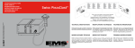
PICJET®
GUNJET
- BETRIEBS- UND WARTUNGSANLEITUNG
- UTILISATION ET ENTRETIEN
- USO E MANUTENZIONE
06.04
2
OL.3001-3002 M. 6
E3) GUNJET INSTALLATION
E3) GUNJET EINBAU
E3) INSTALLATION GUNJET
E3) INSTALLAZIONE GUNJET
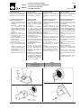
A) Area of installation
- Provide a bore of approx. 75
mm in the indicated position.
- Thoroughly clean the area
around the hole
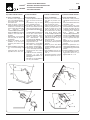
B) Insert the spout in the bore
made and weld the plate connected to it to the wall of the
silo or hopper with a Rutil Basic
electrode
DIN
1913E5153B(R10)AVSE7016,
taking care NOT to ground the
welder to the stud bolts of
the plate.
- Weld the bolt “7” in a position
near the plate as shown in
the diagram.
C) Mount the gasket “2” and
GUNJET “3” on the corresponding stud bolts of the
plate.
D) Fasten GUNJET using washers “4” and self-locking nuts
“5”
- Attach the chain “9” with appropriate nuts “8” and “10”.
A) Einbaubereich
- An der empfohlenen Stelle ein
Loch von circa 75 mm bohren.
- Den Bereich rings um das
Loch sorgfältig reinigen.
B) Die Düse in das vorher gebohrte Loch stecken und die
daran angeschlossene Platte mit der Elektrode Rutil Basico
DIN
1913E5153B(R10)AVSE7016
an der Silo- oder Trichterwand anschweißen, wobei
darauf zu achten ist, dass
das
Massekabel
des
Schweißgeräts NICHT an
die Stiftschrauben der Platte
angeschlossen wird.
- Die Schraube „7" in der Nähe
der Platte in der angegebenen Position anschweißen.
C) Die Dichtung „2" und GUNJET
„3" auf die entsprechenden
Stiftschrauben der Platte
montieren.
D) GUNJET mit den Unterlegscheiben „4" und den
selbstsichernden Muttern „5"
befestigen.
- Die Kette „9" mit den Muttern
„8" und „10" einhaken.
A) Zone d’installation
- Réaliser un trou d’environ 75
mm dans la position conseillée.
- Nettoyer soigneusement la
zone qui entoure le trou.
B) Insérer la buse dans l’orifice
réalisé précédemment, et
souder la plaque qui lui est
relié sur la partoi du silo ou
de la trémie avec une électrode Rutil Basico DIN
1913E5153B(R10)AVSE7016
en prenant soin de NE PAS
relier les fils de masse de la
machine à souder aux goujons de la plaque.
- Souder la vis “7” à proximité
de la plaque, dans la position
indiquée.
C) Monter le joint “2” et le désagrégateur GUNJET “3” sur les
goujons correspondants de
la plaque.
D) Fixer GUNJET avec les rondelles “4” et les écrous de sûreté “5”.
- Accrocher la chaîne “9” avec
les écrous prévus “8” et “10”.
A) Zona d’installazione
- Realizzare nella posizione
consigliata un foro di circa 75
mm
- Pulire accuratamente la zona
circostante il foro.
B) Inserire l’ugello entro il foro
precedentemente realizzato
e saldare la piastra ad esso
collegata sulla parete del silo
o tramoggia con elettrodo
Rutil
Basico
DIN
1913E5153B(R10)AVSE7016,
avendo cura di NON collegare il filo di massa della saldatrice ai prigionieri della piastra.
- Saldare la vite “7” nei pressi
della piastra, nella posizione
indicata.
C) Montare la guarnizione “2” e
il disgregatore GUNJET “3” sui
corrispondenti prigionieri della
piastra.
D) Fissare il GUNJET con rondelle “4” e dadi autobloccanti “5”.
- Agganciare catena “9” con
appositi dadi “8” e “10”