1
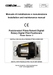
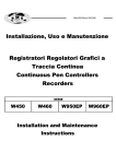
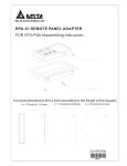
ManR01ne 07/2008
www.omcsrl.com
Installazione
Uso e Manutenzione
Installation, Operation and Maintenance
Instructions
RP01
RE01
POSIZIONATORI PER VALVOLE DI
REGOLAZIONE
CONTROL VALVE POSITIONERS
OMC s.r.l. Industrial Automation Equipment
Our products are manufactured under ISO-9001 Quality Assurance System, approved by CSQ certified under
nr.9190.OMC2 - FIRST ISSUE 1994/08/04
INDICE
INDEX
1. DESCRIZIONE
1. DESCRIPTION
2. DATI TECNICI
2. TECHNICAL DATA
2.1 MATERIALI
2.1 MATERIALS
2.2 PORTATA ARIA RP01 E RE01
2.2 RP01 & PR01 AIR DELIVERY
2.3 PORTATA ARIA RP01HP E RE01HP
2.3 RP01HP & RE01HP AIR DELIVERY
2.4 CONSUMO D'ARIA RP01 E PR01
2.4 RP01 & PR01 AIR CONSUMPTION
2.5 DIMENSIONI DI INGOMBRO
2.5 DIMENSIONS
3. ACCOPPIAMENTO
POSIZIONATORE - VALVOLA
3.1 FUNZIONAMENTO
3. POSITIONER - ACTUATOR
COUPLING
3.1 OPERATION
3. INSTALLAZIONE
3. INSTALLATION
3.1 MONTAGGIO SU ATTUATORE CON
CASTELLO A COLONNE (IEC 534)
3.1 FITTING THE POSITIONER TO PILLAR
TYPE ACTUATOR (IEC 534)
3.2 MONTAGGIO SU ATTUATORE CON
CASTELLO INTEGRALE (IEC 534)
3.2 FITTING THE POSITIONER TO YOKE TYPE
ACTUATOR (IEC 534)
3.3 MONTAGGIO SU ALTRI TIPI DI ATTUATORE
3.3 AVAILABLE FIXING KITS
5. CONNESSIONI ELETTRICHE E
PNEUMATICHE
5. AIR AND ELECTRICAL CONNECTIONS
6. MESSA IN FUNZIONE
6. COMMISSIONING
7. REGOLAZIONE VELOCITÀ
VALVOLA
7. VALVE SPEED
ADJUSTMENT
8. FUNZIONAMENTO IN SPLIT RANGE
8. SPLIT RANGE OPERATION
9. INVERSIONE DELL'AZIONE
9. ACTION REVERSAL
10. MANUTENZIONE
10. MAINTENANCE
11. MALFUNZIONAMENTO: SINTOMI,
CAUSE E RIMEDI
11. TROUBLE CHART: SYMPTOMS,
CAUSES AND ACTION TO TAKE
12. RICAMBI
12. SPARE PARTS
12.1 RE01 e RE01.1
12.1 RE01 & RE01.1
12.2 RP01
12.2 RP01
13. NOTE DI SICUREZZA
13. SAFETY NOTES
14. VERSIONE CON TRASMETTITORE DI
POSIZIONE
14. POSITIONER WITH POSITION
TRANSMITTER
OMC s.r.l. - Via Galileo Galilei, 18 - 20060
Cassina de Pecchi (MI) - ITALY
Tel.: (+39) 02.95.28.468 - Fax: (+39) 02.95.21.495 - [email protected]
Pag.2
1. DESCRIZIONE
1. DESCRIPTION
RP01, RE01 e RE01.1 sono posizionatori a semplice con
segnale in entrata 3÷15 psi o 4÷20 mA per il controllo
proporzionale di attuatori lineari. Gli apparecchi
confrontano il segnale proveniente dall'unità regolante
con la posizione della leva di feedback collegata
all'attuatore. La comparazione tra queste due forze genera
una pressione di uscita che agisce direttamente sulla
membrana dell'attuatore.
The single acting positioners RP01 RE01 and RE01.1
require an input signal of 3÷15 psi / 4÷20 mA for
proportional control valves. The Positioner compares the
output signal from a controller with the position feedback,
and varies a pneumatic output signal to the actuator
accordingly. The valve position is therefore guaranteed
for any controller output signal and the effects of varying
differential pressure, stem friction and diaphragm
hysteresis are overcome.
2. DATI TECNICI
2. TECHNICAL DATA
GRADO DI PROTEZIONE
MONTAGGIO
IEC 534 (NAMUR)
da 3 a 7 mm con molla tipo 1
da 6 a 18 mm con molla tipo 2
da 9 a 33 mm con molla tipo 3
da 14 a 53 mm molla tipo 5
da 35 a 100 mm molla tipo 6
da 100 mm a infinito (*)
CORSA NOMINALE
CONNESSIONI PNEUMATICHE
ARIA DI ALIMENTAZIONE
USCITA
RP01
ERRORE DI
RIPETIBILITA'
RE01 /.1
ERRORE DI ISTERESI
PESO
TEMPERATURA
AMBIENTE
RP01
RE01 /.1
RP01
RE01 /.1
RP01
RE01 /.1
TEMPERATURA
STOCCAGGIO
SEGNALE DI
COMANDO
IP55
IP65 (*)
1/4" NPT
2…10 bar
0....100 % della pressione di
alimentazione
< 0,1 % del campo
< 0,2 % del campo
< 0,6 % del campo
< 1 % del campo
≅1,3 Kg
≅1,4 Kg
-20....+80 °C
-20....+70 °C
-30....+80 °C
RP01
RE01 /.1
CONNESSIONI ELETTRICHE
(R01E / R01E.1)
3÷15 Psi (0,2÷1 bar)
altri segnali (*)
4 ÷ 20 mA
altri segnali (*)
Pressacavo PG9
altre misure (*)
≤ 30 V
Ui
IP55
IP65 (*)
PROTECTION CLASS
MOUNTING
IEC 534 (NAMUR)
NOMINAL TRAVEL RANGE
PNEUMATIC CONNECTIONS
SUPPLY AIR PRESSURE
OUTPUT
RP01
REPEATIBILITY
RE01 /.1
RP01
HYSTERESIS
RE01 /.1
RP01
WEIGHT
RE01 /.1
RP01P
AMBIENT
TEMPERTURE
RE01 /.1
STORAGE
TEMPERATURE
from 3 to 7 mm (spring type 1)
from 6 to 18 mm (spring type 2)
from 9 to 33 mm (spring type 3)
from 14 to 53 mm (spring type 5)
from 35 to 100 mm (spring type 6)
from 100 to >100 mm (*)
1/4" NPT
2…10 bar
0....100 % of the supply air
pressure
< 0,1 % of full range
< 0.2 % of full range
< 0,6 % of full range
< 1 % of full range
≅1,3 Kg
≅1,4 Kg
-20....+80 °C
-20....+70 °C
-30....+80 °C
RP01
INPUT
RE01 /.1
ELECTRIC CONNECTIONS
(R01E / R01E.1)
3÷15 Psi (0,2÷1 bar)
other input (*)
4 ÷ 20 mA
other input(*)
Cable gland PG9
other connections (*)
≤ 30 V
Ui
Ii
≤ 150 mA
Ii
≤ 150 mA
PI
≤ 0,80 W
Pi
≤ 0,80 W
Max 250 Ω
Impedenza
Max 250 Ω
Impedance
Ci
≈ 0 (trascurabile)
Ci
≈ 0 (negligible)
Li
≈ 0 (trascurabile)
Li
≈ 0 (negligible)
* su richiesta
* on request
2.1 MATERIALI
2.1 MATERIALS
CORPO
COPERCHIO
RP01 / RE01
RE01.1
CASSETTO DISTRIBUTORE
MEMBRANA RICEVITORE
In alluminio pressofuso
verniciatura antiacido
Policarbonato
Alluminio
Cassetto: Lega di Rame
Perno: Acciaio INOX
Gomma nitrilica
BODY
COVER
RP01 / RE01
RE01.1
SLIDE VALVE
RECEIVER DIAPHRAGM
Die cast aluminium with anti
corrosive paint
Polycarbonate
Aluminium
Box: Copper Alloy
Pivot: Stainless Steel
Nitrile Rubber
Pag. 3
2.2 PORTATA ARIA RP01 E RE01
2.2 RP01 & PR01 AIR DELIVERY
Prova effettuata con tubo 6 x 8 mm
Test effected with pipe 6 x 8 mm
ALIMENTAZIONE 2 BAR
regolabile da 1 a 10 Nm³/h
2 BAR SUPPLY
adjustable from 1 to 10 Nm³/h
ALIMENTAZIONE 4 BAR
regolabile da 1 a 16 Nm³/h
4 BAR SUPPLY
adjustable from 1 to 16 Nm³/h
ALIMENTAZIONE 6 BAR
regolabile da 1 a 22 Nm³/h
6 BAR SUPPLY
adjustable from 1 to 22 Nm³/h
ALIMENTAZIONE 8 BAR
regolabile da 1 a 28 Nm³/h
8 BAR SUPPLY
adjustable from 1 to 28 Nm³/h
ALIMENTAZIONE 10 BAR
regolabile da 1 a 34 Nm³/h
10 BAR SUPPLY
adjustable from 1 to 34 Nm³/h
2.4 CONSUMO D'ARIA RP01 E RE01
2.4 RP01 & PR01 AIR CONSUMPTION
Prova effettuata con tubo 4 x 6 mm
Test effected with pipe 4 x 6 mm
ALIMENTAZIONE 2 BAR
max 0,2 Nm³/h
2 BAR SUPPLY
max 0,2 Nm³/h
ALIMENTAZIONE 3 BAR
max 0,4 Nm³/h
3 BAR SUPPLY
max 0,4 Nm³/h
ALIMENTAZIONE 4 BAR
max 0,5 Nm³/h
4 BAR SUPPLY
max 0,5 Nm³/h
ALIMENTAZIONE 5 BAR
max 0,6 Nm³/h
5 BAR SUPPLY
max 0,6 Nm³/h
ALIMENTAZIONE 6 BAR
max 0,7 Nm³/h
6 BAR SUPPLY
max 0,7 Nm³/h
ALIMENTAZIONE 7 BAR
max 0,8 Nm³/h
7 BAR SUPPLY
max 0,8 Nm³/h
ALIMENTAZIONE 8 BAR
max 1,0 Nm³/h
8 BAR SUPPLY
max 1,0 Nm³/h
ALIMENTAZIONE 10 BAR
max 1,5 Nm³/h
10 BAR SUPPLY
max 1,5 Nm³/h
Portata - Air Delivery (Nm³/h)
DIAGRAMMA CONSUMI - AIR CONSUMPTION DIAGRAM
1,6
1,4
1,2
1
0,8
0,6
0,4
0,2
0
2
3
4
5
6
7
8
9
10
Alimentazione - Supply (bar)
2.5 DIMENSIONI DI INGOMBRO
2.5 DIMENSIONS
* con prolunga "PSN"
su richiesta
* with "PSN" adapter
on request
181 (226)*
86
70 (115)*
112
180
142
Fig. 2.5
Pag. 4
3. ACCOPPIAMENTO
POSIZIONATORE - VALVOLA
3. POSITIONER - ACTUATOR
COUPLING
3.1 FUNZIONAMENTO
3.1 OPERATION
I posizionatori vengono forniti per il funzionamento in
azione diretta a semplice effetto.
Qualora si voglia invertire l'azione è sufficiente
togliere il tappo dall'uscita "A" (Fig.3 Pag.5) del
posizionatore e chiudere l'uscita "OUT1".
The positioner are normally supplied for single acting
operations and direct action.
In case the reverse action is required then remove
the plug from "A " (Fig.3 Pag.5) and close the
output "OUT1".
ACCOPPIAMENTO POSIZIONATORE - VALVOLA
POSITIONER - ACTUATOR COUPLING
POSIZIONE LEVA DI FEEDBACK
FEEDBACK LEVER POSITION
Fig. 3.1.A
15 PSI / 20 mA
3 PSI / 4 mA
OUT 1
OUT 1
Fig. 3.1.B
3 PSI / 4 mA
15 PSI / 20 mA
AZIONE
ACTION
Posizionatore con
azione diretta:
il
segnale
in
ingresso
cresce,
l'asta dell'otturatore
si muove verso
l'alto
(molle
compresse).
Positioner
with
direct action:
Input signal rises,
plug stem goes up
(actuator
springs
compressed)
Posizionatore con
azione diretta:
il
segnale
in
ingresso
cresce,
l'asta dell'otturatore
si muove verso il
basso
(molle
compresse).
Positioner
with
direct action:
Input signal rises,
plug stem goes
down
(actuator
springs
compressed)
Pag. 5
OPEN
APRIRE
A
Fig. 3
OUT 1
ACCOPPIAMENTO POSIZIONATORE - VALVOLA
POSITIONER - ACTUATOR COUPLING
POSIZIONE LEVA DI FEEDBACK
FEEDBACK LEVER POSITION
CLOSED
CHIUDERE
AZIONE
ACTION
Posizionatore con
azione inversa:
il
segnale
in
ingresso
cresce,
l'asta dell'attuatore
si muove verso il
basso
(molle
decompresse).
Fig. 3.1.C
3 PSI / 4 mA
Positioner
with
reverse action:
Input signal rises,
plug stem goes
down
(actuator
springs
decompressed)
15 PSI / 20 mA
Fig. 3.1.D
15 PSI / 20 mA
3 PSI / 4 mA
Posizionatore con
azione inversa:
il
segnale
in
ingresso
cresce,
l'asta dell'attuatore
si muove verso
l'alto
(molle
decompresse).
Positioner
with
reverse action:
Input signal rises,
plug stem goes up
(actuator
springs
decompressed)
Pag. 6
4. INSTALLAZIONE
4. INSTALLATION
4.1 MONTAGGIO SU ATTUATORE CON CATSTELLO 4.1 FITTING THE POSITIONER TO PILLAR TYPE
1. Per il corretto orientamento del posizionatore controllare la
Fig. 4.1
N.B.: Le istruzioni che seguono si riferiscono alle condizioni
rappresentate nelle Fig. 3.1.A, 3.1.D, 3.2.A e 3.2.A
2. Montare la staffa di fissaggio in posizione centrale sul
castello dell'attuatore, fissandola con i 4 dadi in dotazione
come in Fig. 4.1
3. Fissare il posizionatore sulla staffa utilizzando la vite in
dotazione.
4. Alloggiare il perno di feedback come in Fig. 3.3
1. Check Fig. 4.1 for correct orientation of positioner.
Note: The following instructions assume that the positioner
is to be fitted as Fig. 3.1.A, 3.1.D, 3.2.A e 3.2.A
2. Place the two halves of the mounting bracket either side
of the pillar and hand tighten the 4 bolts. Slide the bracket to
halfway up the pillar.
3. Mount the feedback lever bracket (Fig. 3.3)
4.2 MONTAGGIO SU ATTUATORE CON CASTELLO
INTEGRALE (IEC 534)
4.2 FITTING THE POSITIONER TO YOKE TYPE
ACTUATORS (IEC 534)
1. Per il corretto orientamento del posizionatore controllare la
Fig. 4.2
N.B.: Le istruzioni che seguono si riferiscono alle condizioni
rappresentate nelle Fig. 3.1.A, 3.1.D, 3.2.A e 3.2.A
2. Montare il posizionatore direttamente sul castello
dell'attuatore utilizzando la vite in dotazione.
3. Alloggiare la leva di feedback come in Fig. 3.3
1. Check Fig. 4.2 for correct orientation of positioner.
Note: The following instructions assume that the positioner
is to be fitted as Fig. 3.1.A, 3.1.D, 3.2.A e 3.2.A
2. For yoke type actuators the positioner fits directly to the
yoke via a central bolt. Using the longer of the two bolts
supplied, locate the positioner and tighten.
3. Mount the feedback lever bracket (Fig. 3.3)
Fig. 4.1
Fig. 4.2
4.3 MONTAGGIO SU ALTRI TIPI DI ATTUATORE
4.3 AVAILABLE FIXING KITS
Sono disponibili diversi tipi di staffe che consentono il Different solution of fittings are also available to mount the
fissaggio del posizionatore su qualsiasi tipo di valvola come positioner to any type of valve actuator. See Fig. 4.3.1, 4.3.2
illustrato nelle Fig. 4.3.1, 4.3.2 e 4.3.3
and 4.3.3.
Fig. 4.3.1
Fixing kit 072-55
Kit di fissaggio 072-55
Fig. 4.3.2
Fixing kit 973SUP
Kit di fissaggio 973SUP
Fig. 4.3.3
Valve spindle adaptor 180-23
Adattatore perno di feedback 180-23
Pag. 7
5. CONNESSIONI PNEUMATICHE E
ELETTRICHE
5. AIR AND ELECTRICAL CONNECTIONS
Tutti i collegamenti pneumatici sono facilmente accessibili
(Fig. 5). Per le connessioni elettriche (solo RE01 e RE01.1)
inserire i due fili nel passacavo e collegarli alla morsettiera
interna contrassegnata con "+" e "-" (Fig. 5.1).
Per assicurare il corretto funzionamento del Posizionatore,
l'aria di alimentazione deve essere libera da ogni impurità
quali polveri, ecc. utilizzando un filtro riduttore installato in
linea.
All pneumatic connections are easily accessible externally
(see Fig. 5). Connect two wires to the terminal board "+" and
"-" (RE01 only) (see Fig.5.1).
To ensure trouble free use of this positioner, the air supply
should be conditioned to remove dirt and moisture. A filter
regulator should be fitted upstream of the device.
Electrical connections are made by moving the lid.
ATTENZIONE!
CAUTION!
I posizionatori modello RE01.1
(sicurezza intrinseca) devono essere
alimentati da costruzioni elettriche
associate certificate in conformità alle
norme 60079 che rispettino i limiti delle
caratteristiche elettriche indicate nel
paragrafo 2.
OUTPUT 1
The positioners type RE01.1 (intrinsic
safety) must be feed by electric devices
certificated in conformity with EN 60079
standards. The devices must comply the
electric features mentioned on technical
specification (see chapter 2).
Fig. 5
SEGNALE DI COMANDO (RE01)
INPUT SIGNAL (RE01 / RE01.1)
SUPPLY / ALIMENTAZIONE
SEGNALE DI COMANDO 3 ÷ 15 PSI (RP01)
3 ÷ 15 PSI INPUT SIGNAL (RP01)
Fig. 5.1
INPUT SIGNAL
(RE01 / RE01.1)
4÷20mA IN
6. MESSA IN FUNZIONE
6. COMMISSIONING
1. Controllare che tutti i collegamenti siano corretti e che il
posizionatore sia montato secondo la funzione richiesta (vedi
sezione 3).
2. Inviare un segnale di 4mA (o 3psi) e agire sulla vite di
zero (Fig. 6.1) sino far partire la valvola. A questo punto
girare la vite molto lentamente in senso contrario riportando
l'asta dell'otturatore in posizione di riposo. Controllare
l'indicatore di corsa dell'attuatore.
1. Check that all pneumatic and electrical connections are
correct and that the positioner is mounted according to the
function you require. Refer to section 3.
2. Inject a signal of 4 mA (or 3psi) and adjust the start screw
as per fig. 6.1 such that the position of the valve is at the
fully extended position. At this point the valve plug should
just be touching its seat and any counter rotation of the start
screw causes the valve to retract. Set the valve position
indicator.
Pag. 8
3. Inviare un segnale di 20mA (o 15psi) e controllare che
l'asta dell'otturatore compia la corsa desiderata. In caso
contrario agire sul perno scorrevole (vedi Fig. 6.2).
Controllare l'indicatore di corsa dell'attuatore.
4. E' possibile che nell'esecuzione dell'operazione "3" si
verifichi uno spostamento del punto zero. Se questo accade
è sufficente ripetere le operazioni "2" e "3" per ristabilire le
condizioni volute.
5. Con un segnale di 20mA (o 15psi) controllare che la corsa
compiuta dalla valvola corrisponda a quella indicata
sull'etichetta della valvola stessa.
6. Come controllo finale, inviare un segnale di 12 mA (o 9psi)
e verificare che l'asta dell'otturatore della valvola compia il
50% della corsa.
7. Quando il posizionatore è in funzione è possibile regolare
la portata (vedi Capitolo 7), modificando così la velocità di
intervento dell'attuatore.
3. Inject a signal of 20 mA (or 15psi)and slide the feedback
lever pin such that the valve is in the fully retracted position
(moving the pin towards the end of the lever increases the
movement see fig. 6.2). Set the valve position indicator.
4. Adjustment of the feedback pin will effect slightly the
adjustment of the start screw so steps 2 and 3 will need to
be repeated.
5. With a signal of 20 mA (or 15psi), check that the distance
from the lower valve po<sition indicator and the travel
indicator corresponds to the travel marked on the label of
the valve.
6. As a final check ensure that the valve moves to 50% open
with a signal of 12 mA (or 9psi).
CORREZIONE CORSA
SPAN ADJUSTMENT
Fig. 6.1
Fig. 6.2
CORREZIONE ZERO
ZERO ADJUSTMENT
7. REGOLAZIONE VELOCITÀ VALVOLA
7. VALVE SPEED ADJUSTMENT
Con i posizionatori RP01 e RE01 è possibile regolare le
velocità di apertura e chiusura della valvola.
Per regolare la velocità dell'attuatore agire sulla vite "B"
(fig.7)
A splitted opening / closing speed adjustment of
the valve should be made on RP01 and RE01.
To control the actuator speed: operate on screws "B" (see
fig. 7).
Fig. 7
B
Pag. 9
8. FUNZIONAMENTO IN SPLIT RANGE
8. SPLIT RANGE OPERATION
Parecchie applicazioni richiedono che la valvola esegua il
100% della corsa con il segnale in ingresso ridotto del 50%
(3÷9psi o 9÷15psi per RP01 ; 4÷12mA o 12÷20mA per RE01
e RE01.1). Nel caso sia richiesta questa operazione è
sufficiente correggere la corsa, come descritto nel capitolo
6.
Many applications require the 100% of valve stroke with a
50% reduced input signal (3÷9 psi or 9÷15 psi for RP01;
4÷12mA or 12÷20mA for RE01 & RE01.1). In case this
application is required then the stroke span must be
adjusted as described on item 6.
9. INVERSIONE DELL'AZIONE
9. ACTION REVERSAL
I posizionatori vengono forniti per il funzionamento in azione Positioners are provided to operate on a single acting
diretta a semplice effetto. Per invertire l'azione è sufficiente actuator with direct action mode. To reverse the action see
seguire le indicazioni del capitolo 3.
the description on item 3.
10. MANUTENZIONE (solo RE01 e RE01.1)
10. MAINTENANCE (only RE01 and RE01.1)
Le impurità contenute nell'aria di alimentazione (olii, polveri,
acqua, ecc...), sono la principale causa delle anomalie di
funzionamento del posizionatore.
Esse si depositano all'interno del posizionatore stesso
ostruendone le parti vitali.
L'utilizzo di un filtro sull'aria di alimentazione diminuisce, ma
non vieta, il formarsi di depositi.
Periodicamente occorre quindi
rimuovere le eventuali
impurità come segue:
1) Chiudere l'alimentazione al posizionatore.
2) Svitare la vite "A" (vedi Fig.8)
3) Estrarre il particolare "B"
4) Pulire il foro calibrato con c'apposito pulitore "C" posto
all'interno del coperchio
The incoming air impurities (oil, dust, water etc..) are the
main cause of positioner failures.
These impurities seep into the internal parts of the
equipment which get occluded consequently.
The use of an air filter upstream reduces the internal
sediments but it does not exclude them completely.
To avoid any failure caused by the impurities then clean
periodically the nozzle as follow:
1) Stop the air feed
2) Unloose the screw "A" (see fig.8)
3) Pull out the nozzle plate "B"
4) Clean the calibrated orifice with the nozzle cleaner "C"
which is located on the positioner cover
The frequency of such cleaning operation depends on the
La periodicità di tali operazioni dipende dalla qualità dell'aria air feed quality.
di alimentazione.
Fig. 8
B
A
C
Pag. 10
11. MALFUNZIONAMENTO: SINTOMI, CAUSE E
RIMEDI
11. TROUBLE: SYMPTOMS, CAUSES AND
ACTION TO TAKE
ATTENZIONE!
CAUTION!
Prima di compiere questa manovra,
assicurarsi che il posizionatore non sia
alimentato.
Before be over this operate, make sure
that the positioner has not in pressure.
Prima di mettere mano allo strumento, verificare quanto Before operating the unit, please check:
segue:
- the unit proper supply
- corretta alimentazione dello strumento
- the pneumatic and process connections
- collegamenti pneumatici e di processo
- the good operating conditions and status of the valve
- buon funzionamento e stato della valvola
SINTOMO
CAUSA
RIMEDIO
SYMPTOM
CAUSE
Velocità di apertura e
L'attuatore pendola e
Diminuire la velocità.
chiusura della valvola
non si stabilizza.
Vedi capitolo 7
elevata.
Actuator hunting
Opening/Closing
Reduce the speed. See
valve speed too high chapter 7
Velocità di apertura e
L'attuatore si muove
Aumentare la velocità.
chiusura della valvola
molto lentamente.
Vedi capitolo 7
bassa.
Actuator motion is
too slow.
Opening/Closing
valve speed too low
Increase the speed.
See chapter 7
Strozzatura ostruita Correggere.
da depositi di impurità Vedi capitolo 10
The orifice is
obstruct from
impurity
Reverse its position
See chapter 10
Connessioni
pneumatiche tra
posizionatore e
attuatore invertite
Pneumatic
connection between
Reverse its position
actuator and
See chapter 3
positioner has been
inverted
Correggere.
Vedi capitolo 3
Il posizionatore non Coordinamento tra
Correggere.
regola correttamente attuatore e
Vedi capitolo 3
apertura e chiusura posizionatore errato.
dell'attuatore.
ACTION TO TAKE
Actuator and
Adjust.
positioner coupling is
Positioner with
See chapter 3
wrong control action not correct
Collegamenti elettrici
Correggere.
invertiti. (RE01 e
Vedi capitolo 5
RE01.1)
Electric connections
has been inverted
(RE01& RE01.1 only)
Adjust.
See chapter 5
Mancanza del
Controllare e correggere
segnale di comando
Control signal
missing
Check and adjust
Mancanza aria di
alimentazione
Supply air missing
Check and adjust
Controllare e correggere
Velocità di apertura e
L'attuatore si muove
Diminuire la velocità.
chiusura della valvola
troppo velocemente.
Vedi capitolo 7
elevata.
Actuator motion is
too high.
Opening/Closing
Reduce the speed. See
valve speed too high chapter 7
L'attuatore non
compie il campo
desiderato
Correggere.
Vedi capitolo 6
Actuator span
inadequate
Span adjustment is
wrong
Adjust.
See chapter 6
Correggere.
Vedi capitolo 6
Actuator start point
shifted
Zero adjustment
missing
Adjust.
See chapter 6
Regolazione di
campo errata
L'attuatore non parte
Regolazione di zero
dalla posizione
errata
desiderata
Pag. 11
12. RICAMBI
12. SPARE PARTS
12.1 RE01 e RE01.1
12.1 RE01 and RE01.1
072-46
200-25
MOLLA
SPRING
200-32
988SRE
200-30
180-20
180-12
988DLE
110-145
110-164
R01E
R01E.1
180-19
972GMZ
180-22
180-21
200-31
200-44
073-105
073-106
RE01.1
RE01.1
RE01
RE01
INPUT mA
INPUT Volt
INPUT mA
INPUT Volt
Pag. 12
12.2 RP01
12.2 RP01
072-46
200-25
MOLLA
SPRING
988SRP
200-30
180-20
180-12
988DLP
180-19
972GMZ
180-22
180-21
13. NOTE DI SICUREZZA (SOLO RE01.1)
13. SAFETY NOTES (ONLY RE01.1)
ATTENZIONE!
CAUTION!
I posizionatori modello RE01.1 (sicurezza intrinseca)
devono essere alimentati da costruzioni elettriche
associate certificate in conformità alle norme EN
60079 che rispettino i limiti delle caratteristiche
elettriche indicate nel paragrafo 2.
The positioners type RE01.1 (intrinsic safety) must be
feed by electric devices certificated in conformity with
EN 60079 standards. The devices must comply the
electric features mentioned on technical specification
(see chapter 2).
Pag. 13
14. VERSIONE CON TRASMETTITORE DI
POSIZIONE
14. POSITIONER WITH POSITION
TRANSMITTER
Per la messa in funzione del trasmettitore di posizione
seguire la seguente procedura:
1) Eseguire i collegamenti come in Fig. 5.
2) Portare la valvola in condizione di riposo
3) Agire sulla leva "A" portando il segnale di ritrasmissione a
4 mA.
4) Far compiere alla valvola la corsa desiderata.
5) Verificare che il trasmettitore di posizione invii un segnale
di 20 mA. In caso contrario agire sul trimmer "C".
6) E' possibile che nell'esecuzione dell'operazione "4" si
verifichi uno spostamento del punto zero. Se questo accade
è sufficente ripetere l'operazione "4" agendo unicamente sul
trimmer "B".
Start the position transmitter as follows:
1) Perform the connections as shown in Fig. 5.
2) Put the valve in non-working position.
3) Check that the position transmitter emits a 4mA signal.
If the signal is superior to 4mA use the lever "A", if it is
inferior to 1mA use the trimmer "C" to eliminate the
difference.
4) Let the valve perform the stroke required.
5) Check that the position transmitter emits a 20mA signal.
If it does not, use the trimmer "C".
6) When performing the procedure at par.4, a zero shift
may occur. In this case, simply repeat the procedure at
par.4 by only using the trimmer "B".
Segnale di comando
24 V c.c.
IN
LOAD
Segnale di ritrasmissione
1 2 3 4 5
B
C
A
B = Zero
C = Campo
B = Zero adjustment
C = Span adjustment
Pag. 14