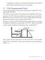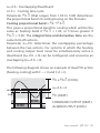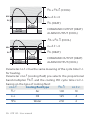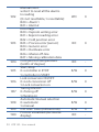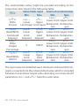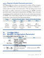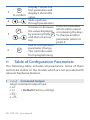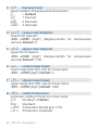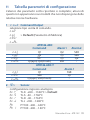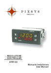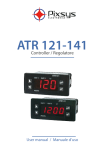
1
User’s Guide Shop online at omega.com ® e-mail: [email protected] For latest product manuals: www.omegamanual.info MADE IN ITALY CN142 Controller omega.com [email protected] Servicing North America: U.S.A.: Omega Engineering, Inc., One Omega Drive, P.O. Box 4047 Stamford, CT 06907-0047 USA Toll-Free: 1-800-826-6342 (USA & Canada only) Customer Service: 1-800-622-2378 (USA & Canada only) Engineering Service: 1-800-872-9436 (USA & Canada only) Tel: (203) 359-1660 Fax: (203) 359-7700 e-mail: [email protected] For Other Locations Visit omega.com/worldwide The information contained in this document is believed to be correct, but OMEGA accepts no liability for any errors it contains, and reserves the right to alter specifications without notice. WARNING: These products are not designed for use in, and should not be used for, human applications. Summary 1 2 3 4 5 6 7 8 Model Identification......................................................................... 7 Technical Data................................................................................... 7 2.1 General Features...................................................................... 7 2.2 Hardware Features.................................................................. 8 2.3 Software Features................................................................... 9 Dimensions and Installation.......................................................... 9 Electrical wirings ...........................................................................10 4.1 Wiring diagram......................................................................10 Configuration EASYUP...................................................................14 Display and Keys Functions..........................................................15 6.1 Numeric Indicators (Display)..............................................15 6.2 Meaning of Status Lights (Led)..........................................15 6.3Keys........................................................................................16 Controller Functions.......................................................................16 7.1 Modifying Main Setpoint and Alarm Setpoint Values.. 16 7.2Auto-Tune................................................................................17 7.3 Manual Tuning.......................................................................17 7.4 Automatic Tuning ................................................................17 7.5 Soft Start..................................................................................18 7.6 Automatic/Manual Regulation for % Output Control.18 7.7 Pre-Programmed Cycle........................................................19 7.8 Memory Card (optional)......................................................20 7.9 Loading default values........................................................21 7.10 LATCH ON Functions.............................................................21 7.11 Digital Input Functions........................................................23 7.12 Dual Action Heating-Cooling.............................................24 Timer operation...............................................................................27 8.1 Single Timer............................................................................27 User manual - ATR 142 3 8.2 Dual Timer..............................................................................28 8.3 Dual Sequential Timer.........................................................28 8.4 Dual Timer Loop...................................................................29 8.5 Relating Timers to Alarms..................................................30 9 Serial Communication...................................................................31 9.1Slave ........................................................................................31 9.2Master......................................................................................37 9.2.1Master Mode in retransmission.........................................37 9.2.2Master Mode Remote process............................................39 10Configuration..................................................................................39 10.1 Modify Configuration Parameter......................................39 11 Table of Configuration Parameters............................................40 12 Alarm Intervention Modes............................................................55 13 Table of Anomaly Signals.............................................................60 14 Summary of Configuration parameters....................................61 4 ATR 142 - User manual Sommario 1 2 3 4 5 6 7 Identificazione del modello..........................................................64 Dati tecnici.......................................................................................64 2.1 Caratteristiche generali.......................................................64 2.2 Caratteristiche hardware....................................................65 2.3 Caratteristiche software......................................................66 Dimensioni e installazione...........................................................66 Collegamenti elettrici ...................................................................67 4.1 Schema di collegamento.....................................................67 Configurazione EASYUP................................................................71 Funzione dei visualizzatori e tasti...............................................72 6.1 Indicatori numerici (display)...............................................72 6.2 Significato delle spie di stato (led).....................................72 6.3Tasti........................................................................................73 Funzioni del regolatore.................................................................73 7.1 Modifica valore setpoint principale e setpoint di allarme.........................................................................73 7.2Auto-tune................................................................................74 7.3 Lancio del Tuning Manuale................................................74 7.4 Tuning Automatico ..............................................................74 7.5 Soft Start..................................................................................75 7.6 Regolazione automatico/manuale per controllo % uscita....................................................................75 7.7 Ciclo pre-programmato.......................................................76 7.8 Memory Card (opzionale)...................................................77 7.9 Caricamento valori di default............................................78 7.10 Funzione LATCH ON..............................................................78 7.11 Funzioni da Ingresso digitale.............................................80 7.12 Funzionamento in doppia azione (caldo-freddo).........81 Manuale d’uso - ATR 142 5 8 Funzioni Timer.................................................................................84 8.1 Singolo Timer.........................................................................84 8.2 Doppio Timer.........................................................................85 8.3 Doppio Timer Sequenziale..................................................86 8.4 Doppio Timer Loop...............................................................87 8.5 Associazione Timer - Allarmi..............................................87 9 Comunicazione Seriale..................................................................89 9.1Slave ........................................................................................89 9.2Master......................................................................................94 9.2.1Modalità master in ritrasmissione....................................94 9.2.2Modalità master processo remoto....................................96 10Configurazione................................................................................97 10.1 Modifica parametro di configurazione............................97 11 Tabella parametri di configurazione..........................................98 12 Modi d’intervento allarme......................................................... 114 13 Tabella segnalazioni anomalie................................................ 119 14 Promemoria configurazione..................................................... 120 6 ATR 142 - Manuale d’uso Introduction Thank you for choosing a Omega controller. With the CN142 model Omega makes available in a single device multiple options related to sensor input and actuators command in addition to the extended power range 24…230 as relay or SSR command, the user or retailer can reduce stock by rationalising investment and device availability. The series includes a version equipped with serial communication Memory cards which are provided with internal battery and therefore do not require cabling to power the controller. Refer to the table below to easily select preferred model. Technical Data General Features Display Operating temperature Sealing Material Weight User manual - ATR 142 7 Hardware Features via software. Thermocouple type: K, S, R, J. Automatic compensation of cold Analogue input Thermoresistance: scale) for thermocouple input, thermo- resistance and V/mA. Cold junction accuracy Impedance: NTC2252 ohm Linear Potentiometers: Relay output SSR output (CN142-ABC) (CN142-ABC-T) Contacts: for resistive loads command and/or alarm for resistive loads output command output and/ or alarm output. Power supply Supply 8 ATR 142 - User manual Power consumption Software Features Regulation ON-OFF with hysteresis. algorithms P, PI, PID, PD with proportional time Proportional band Integral time Derivative time Controller functions alarms, protection of command and alarm setpoints, activation of functions via digital input, preset cycle with Start/Stop. Dimensions and Installation Frontal panel cut-out Dima di foratura 28.5 x 70.5 mm Suggested thickness Spessore suggerito 2 ÷ 8 mm Guarnizione per 32x74 Cod. 1600.00.082 (optional) Gasket for 32x74 Memory Card (optional) Cod. MEMORY 2100.30.005 42mm inserimento Memory Card 42mm insert Memory Card 1 CN1 6 Memory Card (optional) with battery Cod. MEMORY 2100.30.003 U1 C1 6 35 mm CN1 2 1 1 3 77 mm 7 53 mm User manual - ATR 142 9 Electrical wirings Although this controller was designed to resist electromagnetic interferences in industrial environments, please observe following safety guidelines: • Separate the control line from the power wires. • Avoid proximity of remote control switches, electromagnetic contactors, powerful engines and in all instances • Avoid proximity of power groups, especially those with phase control Wiring diagram CNxxx-xxT CNxxx-xx 2 wire 2 wire 4/20mA Power 3A 230V Cosf 0.8 1A 230V Cosf 0.8 Q1 SUPPLY 7 8 9 10 11 SUPPLY Tc - 12 1 1 Memory CN142-ABC 2 Q1 3 4 +VDC PTC/NTC RS485 5 6 SSR - 7 8 9 10 11 Memory CN-ABC-T Power Supply 2 24...230V AC/DC 1 Switching power supply with extended range 10 ATR 142 - User manual Tc + 6 + 5 + 4 + 3 - PT/NI100/1K 3A 230V Cosf 0.8 + 2 + 1 +VDC PTC/NTC SSR 1 V/I 10A 23a0V Cosf 1 PT/NI100/1K Q2 + - V/I - + 5A 230V Cosf 1 + 10A 230V Cosf 1 4/20mA I I Power 12 - 11 AN1 Analogue Input For thermocouples K, S, R, J. • Comply with polarity • For possible extensions, use Shield/Schermo compensated cable and terminals suitable for the thermocouples used(compensated) • When shielded cable is used, it should be grounded at one side only For thermoresistances PT100, NI100 Shield/Schermo • For the three-wire connection use A wires with the same section • For the two-wire connection shortB circuit terminals 10 and 12 • When shielded cable is used, it should be grounded at one side only C Tc + 12 11 PT/NI100 10 12 RED 10 WHITE 11 RED 12 Shield/Schermo 11 PTC/NTC 10 For thermoresistances NTC, PTC, PT500, PT1000 e potentiometers • When shielded cable is used, it should be grounded at one side only to avoid ground loop currents 9 +VDC 10 Shield/Schermo - 11 V/I + 12 For linear signals V/mA • Comply with polarity • When shielded cable is used, it should be grounded at one side only User manual - ATR 142 11 Examples of Connection for linear input 12 For signals 0….10V • Comply with polarity 0...10V 11 12 For signals 0/4….20mA with three-wire sensor • Comply with polarity C = Sensor output B = Sensor ground A = Sensor power supply (12V/30mA) C 0/4...20mA 11 B 9 A PRESSURE TRANSMITTER SENSORE DI PRESSIONE 12 C For signals 0/4..20mA with external power of sensor • Comply with polarity C = Sensor output B = Sensor ground 0/4...20mA 11 B EXTERNAL SUPPLY ALIMENTAZIONE ESTERNA PRESSURE TRANSMITTER SENSORE DI PRESSIONE 12 C For signals 0/4...20mA with two-wire sensor • Comply with polarity C = Sensor output A = Sensor power supply (12V/30mA) 4...20mA 9 A PRESSURE TRANSMITTER SENSORE DI PRESSIONE Serial input - RS485 Modbus RTU communication 6 RS485 + 7 Shield/Schermo 11 Do not use LT (line termination) resistors • For networks with more than five instruments supply in low voltage 12 ATR 142 - User manual Relay Q1 Output 7 Q2 6 Capacity: Q1: 8A, 250Vac,resistive loads,10 5 operations. 30/3A, 250Vac, cosφ=0.3, 10 5 operations. Q2: 5A, 250Vac, resistive loads, 105 operations. 20/2A, 250Vac, cosφ=0.3, 10 5 operations. 5 4 Q1 3 SSR output 8 SSR command output 12V/30mA SSR 9 Digital Input 10 11 Digital input according to parameter DGT.i. The use of digital input in this version is possible only with TC sensors or 0…10V, 0/4…20mA and 0…40mV signals User manual - ATR 142 13 To simplify the setting of parameters and the integration of Omega introduces the EASY-UP coding which allows to set sensors and/or command outputs in a single step. By means of the code listed in the data sheet enclosed to the sensor or actuator (SSR, motorized valve etc..) the EASY-UP coding will set the relevant main parameters on the controllers (ex. selection of PT100 on parameter “Sensor” and the corresponding measuring range on parameters “Lower and Upper limits of setpoint”) signal. 14 ATR 142 - User manual 6 Display and Keys Functions 1 ATR 142 9 12 1 2 3 M T R 10 3 6.1 1 2 6.2 4 5 6 11 7 8 2 Numeric Indicators (Display) Normally displays the process. During the 1234 configuration phase, it displays the parameter being inserted. Normally displays the setpoint. During the 1234 configuration phase, it displays the parameter value being inserted. Meaning of Status Lights (Led) 2 ON when the output command is on. For motorised valve command, led is ON when valve is opening and blinks when closing. ON when alarm 1 is on. 5 3 ON when alarm 2 is on. 6 M 7 T 8 R ON when the “Manual” function is on. ON when the controller is running an “Autotuning” cycle. ON when the controller communicates via serial port. 3 1 4 User manual - ATR 142 15 6.3 Keys 9 10 11 SET 12 FN C 7 7.1 • Allows to decrease main setpoint. • During configuration phase, allows to slide through parameters. Together with SET key it modifies them. • Pressed after SET key it allows to decrease alarm setpoint. • Allows to increase main setpoint. • During configuration phase, allows to slide through parameters. Together with SET key it modifies them. • Pressed after SET key it allows to increase alarm setpoint. • Allows to display alarm setpoint and runs the autotuning function. • Allows to modify configuration parameters. • Allows to run the autotuning function and to select Manual/automatic operation. • Allows to enter/exit for configurator procedure. Controller Functions Modifying Main Setpoint and Alarm Setpoint Values Setpoint value can be changed by keyboard as follows: Press Effect Do Value on display 2 Increase or decrease 9 or changes main setpoint Visualize alarm 10 SET setpoint on display 1 Increase or decrease Value on display 2 11 the alarm set point or changes value 16 ATR 142 - User manual 7.2 Auto-Tune Tuning procedure calculates the controller parameters and can be manual or automatic according to selection on parameter 46 tune. 7.3 Manual Tuning Manual procedure allows the user greater flexibility to decide when to update PID algorithm parameters. The procedure can be activated in two ways. • Running Tuning by keyboard: Press FNC key until display 1 shows the writing tune with , display 2 shows on. The display 2 showing oFF, press T led switches on and the procedure begins. • Running Tuning by digital input: Select tune on parameter 50 dGt.i. At first activation of digital input (commutation on front panel) T led switches on and at second activation switches off. 7.4 Automatic Tuning Automatic tuning activates whenever the controller is switched on or when the setpoint is modified to a value over 35%. To avoid an overshoot, the threshold where the controller calculates new PID parameters is determined by the setpoint value minus the “Set Deviation Tune” (Parameter 47 s.d.tu.). To exit Tuning and keep PID values unchanged, just press the FNC key until display 1 shows the writing tune with the display , display 2 shows off. showing on, press The T led switches off and the procedure finishes. User manual - ATR 142 17 7.5 Soft Start To reach the setpoint the controller can follow a gradient expressed in units (e.g. degree/hour). Enter this gradient on parameter 51 Grad. with the chosen units/hour; only on subsequent activation the controller uses soft start function. Automatic/manual tuning cannot be enabled if the Soft start is active. 7.6 Automatic/Manual Regulation for % Output Control This function allows to select automatic functioning or manual command of the output percentage. Parameter 49 Au.ma., can select two methods. • First selection en. pressing the FNC key display 1 shows p.---, while display 2 shows Auto. key to select man. mode; it is now possible, to Press the and change the output percentage using the keys . To return to automatic mode, using the same procedure, select auto on display 2: M led switches off and functioning returns to automatic mode. • Second selection en.st. same functioning, but with two important variants: • If there is a temporary power failure or after switch-off, manual functioning as well as the previous output percentage value will be maintained at restarting. • If the sensor breaks during automatic functioning, controller moves to manual mode while maintaining the 18 ATR 142 - User manual output percentage command unchanged as generated by the PID immediately before breakage. 7.7 Pre-Programmed Cycle Setpoint Pre-programmed cycle function activates by setting pr.cY. on parameter 48 op.Mo. Controller reaches setpoint1 basing on the gradient set on parameter 51 Grad., then it reaches max. power up to setpoint2. When the process reaches max. power, this setpoint is maintained for the time set on parameter 52 ma.t.i. At expiry, process will reach ambient temperature according to gradient entered on parameter 64 fa.Gr., then command output will be disabled and display will visualize Stop. Setpoint 2 Max Power Max Potenza Maintenance time Mantenimento Cooling Raffreddamento Setpoint 1 Rising gradient Gradiente di salita Time Cycle starts at each activation of the controller, or via digital input if it is enabled for this type of functioning (parameter 50 dGt.i.). User manual - ATR 142 19 7.8 Memory Card (optional) Parameters and setpoint values can be duplicated from one controller to another using the Memory card. There are two methods: • With the controller connected to the power supply Insert the memory card when the controller is off. On activation display 1 shows memo and display 2 show ---- (Only if the correct values are saved in the memory card). By pressing the key display 2 shows Load, then confirm using the FNC key. The controller loads the new data and starts again. • With the controller not connected to power supply. The memory card is equipped with an internal battery with an autonomy of about 1000 operations. Insert the memory card and press the programming button . When writing the parameters, the led turns to red and on completing the procedure it turns to green. It is possible to repeat the procedure without any particular attention. Updating Memory Card To update the memory card values, follow the procedure described for the first method, setting display 2 to ---- so as not to load the parameters on controller1. Enter configuration level and change at least one parameter. Exit configuration. Changes are saved automatically. WARNUNG 1 If on activation the controller does not display memo it means no data have been saved on the memory card, but it is possible to update values. 20 ATR 142 - User manual 7.9 Loading default values This procedure allows to restore factory settings of the device Press Effect Do Display 1 shows 0000 with the 1st digit FN C 1 for 3 sec. flashing, while display 2 shows pass Change the flashing digit and move to the 2 Enter password 9999 or next one using the SET key. 3 Instrument loads SET to confirm default settings Turn off and restart the instrument 7.10 LATCH ON Functions For use with input Pot.1 (potentiometer 6KΩ) and Pot.2 (potentiometer 150KΩ) and with linear input (0…10V, 0...40mV, 0/4…20mA), it is possible to associate start value of the scale (parameter 6 Lo.L.i.) to the minimum position of the sensor and value of the scale end (parameter 7 up.L.i.) to the maximum position of the sensor (parameter 8 Latc. configured as std.). It is also possible to fix the point in which the controller will display 0 (however keeping the scale range between Lo.L.i. and up.L.i.) using the “virtual zero” option by setting u.0st. or u.0in. in parameter 8 Latc. If you set u.0in. the virtual zero will reset after each activation of the device; if you set u.0st. the virtual zero remains fixed once tuned. To use the LATCH ON function, configure according to required operation the parameter Latc.2 2 The tuning procedure starts by exiting the configuration after changing the parameter. User manual - ATR 142 21 For the calibration procedure refer to the following table: Press Effect Do Place the sensor on the Exit parameters minimum operating 1 FNC configuration. Display 2 position (associated with shows the writing Latc. Lo.L.i.) Place the sensor on the Set the value to maximum operating 2 minimum. position The display shows Low (associated with up.L.i.) To exit standard Set the value to procedure press FNC . maximum. For “virtual zero” 3 The display shows HiGt settings place the sensor on zero point. Set the virtual zero value. The display shows uirt. NB: for selection To exit the procedure 4 SET of u.0in. the procedure press FNC . on point 4 should be followed at each re-activation. Min 22 ATR 142 - User manual Max Zero 7.11 Digital Input Functions On ATR142 model, digital input can be enabled by using parameters 48 op.mo. and 50 dGt.i. • Parameter 48 op.mo. cont.: Operating as controller. NB: When using this settings, parameter 50 dGt.i. is ignored. 2t.s.: Switch two thresholds setpoint: with open contact ATR142 regulates on SET1; with closed contact regulates on SET2; 2t.s.i.: Switch two thresholds setpoint: setpoint selection is done by an impulse on digital input; 3t.s.i.: Switch three thresholds setpoint by an impulse on digital input; 4t.s.i: Switch four thresholds setpoint by an impulse on digital input; p.r.c.Y.: Pre-programmed cycle (par. 7.7). key. Setpoints values can be modified any time pressing • Parameter 50 dGt.i. NB: Settings on this parameter are available only if cont. or pr.cY. are selected on parameter 48 op.mo. st.st.: Start / Stop; operating on digital input the controller switches alternatively from start to stop; rn.n.o.: Run N.O. Controller is in start only with closed input; rn.n.c. : Run N.C. Controller is in start only with open input; L.c.n.o.: With closed input allows to lock the reading of sensors; Lc.n.c.: With open input allows to lock the reading of sensors; tune: Enables/disables Tuning function if parameter 46 User manual - ATR 142 23 tune is selected as man.; a.ma.i.: If parameter 49 au.ma. is selected as en. or en.st. controller switch from automatic to manual functioning; a.ma.c.: If parameter 49 au.ma. is selected as en. or en.st. ATR142 works in automatic mode if input is open or in manual mode if input is closed. t.1.s.s.: timer 1 Start/Stop, (par. 8.) NB: digital input functions are not available with sensors PT100, NI100, NTC, PTC, PT500, PT1000 and potentiometers. 7.12 Dual Action Heating-Cooling ATR142 is suitable also for systems requiring a combined heating-cooling action. Main command output must be configured foe hearting PID ( act.t. = Heat and p.b. must be greater than 0), and one of the alarms (AL.1 or AL. 2) must be configured as cooL. Command output must be connected to the actuator responsible for heat, while the alarm output will control cooling action. Parameters to configure for the Heating PID are: act.t. = Heat Command output type (Heating) p.b. : Heating proportional band t.i. : Integral time of heating and cooling t.d. : Derivative time of heating and cooling t.c. : Heating time cycle The parameters to configure for the Cooling PID are the following (example: action associated to alarm1): AL. 1 = cooL Alarm1 selection (cooling) p.b.m. : Proportional band multiplier 24 ATR 142 - User manual ou.d.b. : Overlapping/Dead band co.t.c. : Cooling time cycle Parameter p.b.m. (that ranges from 1.00 to 5.00) determines the proportional band of cooling basing on the formula: Cooling proportional band = p.b. * p.b.m. This gives a proportional band for cooling which will be the same as heating band if p.b.m. = 1.00, or 5 times greater if p.b.m. = 5.00. The integral time and derivative time are the same for both actions. Parameter ou.d.b. determines the overlapping percentage between the two actions. For systems in which the heating and cooling output must never be simultaneously active a dead band ( ou.d.b. ≤ 0) can be configured, and viceversa an overlapping ( ou.d.b. > 0). The following diagram shows an example of dual PID action (heating-cooling) with t.i. = 0 and t.d. = 0. P.b. x P.b.m. (COOL) ou.d.b < 0 SPV P.b. (HEAT) PV ATTIVO ACTIVE ATTIVO ACTIVE COMMAND OUTPUT (HEAT) ALARM OUTPUT (COOL) User manual - ATR 142 25 P.b. x P.b.m. (COOL) SPV ou.d.b = 0 PV P.b. (HEAT) ATTIVO ACTIVE COMMAND OUTPUT (HEAT) ALARM OUTPUT (COOL) ATTIVO ACTIVE P.b. x P.b.m. (COOL) ou.d.t > 0 SPV P.b. (HEAT) PV ATTIVO ACTIVE COMMAND OUTPUT (HEAT) ALARM OUTPUT (COOL) ATTIVO ACTIVE Parameter co.t.c. has the same meaning of the cycle time t.c. for heating. Parameter coo.F. (cooling fluid) pre-selects the proportional band multiplier P.b.m. and the cooling PID cycle time co.t.c. basing on the type of cooling fluid: coo.f. P.b.m. co.t.c. Cooling fluid type Air 1.00 10 Air oiL H2o 26 ATR 142 - User manual Oil 1.25 4 Water 2.50 2 8 Timer operation Timer operation is enabled by parameter 63 tmr.f. To modify duration of counting time, follow the steps below: Press Effect Do Press until tim. 1 or 1 tim. 2 visualized on SET display 1. Increase or decrease Digits on display 2 time value for the 2 or changes. selected timer. Below a description of available options for Timer operation. 8.1 Single Timer This option enables one single Timer and the time is selectable by the operator. To achieve this operation set parameter 63 tmr.f. as follows: • s.tm.s. (Single Timer Seconds) time-basis in seconds (mm.ss) • s.tm.m. (Single Timer Minutes) time-basis in minutes (hh.mm) To start/stop the Timer, press FNC for 1 “. During the counting, Led R is On and display2 shows decrementing time. At elapsing of Timer, led R switches off and display 2 flashes, visualising the programmed time until any key is pressed. Start/Stop of Timer is possibile also by digital input, selecting t.1.s.s. on parameter 50 dGt.i. User manual - ATR 142 27 8.2 Dual Timer This option enables two Timers and the time is selectable by the operator: timers cannot be started at same time. To achieve this operation set parameter 63 as follows: • d.tm.s. (Double Timer Seconds) time-basis in seconds (mm.ss) • d.tm.m. (Double Timer Minutes) time-basis in minutes (hh.mm) Check the table below for the Start procedure: Press Effect Do Press until tim. 1 or tim. C N 1 F 2 visualized on display 1. Start the Timer. Display 2 Back to point 1, after shows decrementing time selection of running Timer and Led R switches on 2 to stop counting. press (fixed for timer 1, flashing Led R switches off. for timer 2). At elapsing of Timer the led R switches off and display 2 flashes, showing the programmed time until any key is pressed. Start/Stop of Timer by digital input is NOT available for Dual Timer mode. 8.3 Dual Sequential Timer This option enables two Timers and the time is selectable by the operator. At elapsing of Timer 1, counting of Timer 2 will automatically start . At elapsing of Timer 2, counting will stop. To achieve operation of dual sequential Timer set the parameter 63 tmr.f. as follows: • d.s.t.s. (Double Sequential Timer Seconds) time-basis in seconds (mm.ss) • d.s.t.m. (Double Sequential Timer Minutes) time-basis in minutes (hh.mm) 28 ATR 142 - User manual To start/stop the Timer, press key FNC for 1“. During the counting, Led R is On (fixed for Timer 1, flashing for Timer 2) and display2 shows decrementing time. Start is always made on Timer 1. At elapsing of Timer, led R is switched off and display 2 shows setpoint value. Start/Stop of Timer is possibile also by digital input, selecting t.1.s.s. on parameter 50 dGt.i. 8.4 Dual Timer Loop This option enables 2 Timers and the time value is selectable by the operator. At elapsing of one Timer, the other one will automatically start and this sequence is repeated cycling. To achieve operation of dual timer loop set the parameter 63 tmr.f. as follows: • d.t.L.s. (Double Timer Loop Seconds) time-basis in seconds (mm.ss) • d.t.L.M. (Double Timer Loop Minutes) time-basis in minutes (hh.mm) To start/stop the Timer, press FNC for 1 “. During the counting, Led R is On (fixed for Timer1, flashing for Timer 2) and display2 shows decrementing time. Start is always made on Timer 1. Start/Stop of Timer is possibile also by digital input, selecting t.1.s.s. on parameter 50 dGt.i. User manual - ATR 142 29 8.5 Relating Timers to Alarms It is possible to associate the alarms (relay or SSR outputs) to the timers by parameters 23 aL. 1 and 31 aL. 2. The table below is showing the combined operation of alarms and Timers. Selection Description par. 23 or 31 Alarm active as long as Timer 1 is in t.1.s.a. Timer 1 Start Alarm Start mode (Timer active) Alarm active at elapsing of Timer1 until any key is pressed. Option not available t.1.E.a. Timer 1 End Alarm for Dual sequential Timer and Dual Timer Loop. t.1.W.a. Timer 1 Warning Expiring Alarm active for the last 5” of Timer1 Alarm active as long as Timer 2 is in t.2.s.a. Timer 2 Start Alarm Start mode (Timer active) Alarm active at elapsing of Timer2 until any key is pressed. Option not available t.2.e.a. Timer 2 End Alarm for Dual sequential Timer and Dual Timer Loop. t.2.w.e. Timer 2 Warning Expiring Alarm active for the last 5” of Timer2 Alarm active as long as Timers 1 and 2 t.1.2.s. Timer 1-2 Start Alarm are in Start mode (Timers active) Alarm active at elapsing of Timers 1 and 2 until any key is pressed. Option not t.1.2.e. Timer 1-2 End Alarm available for Dual sequential Timer and Dual Timer Loop. 30 ATR 142 - User manual t1 . . 2. w. expiring Serial Communication Slave CN142-ABC-T is equipped with RS485, it can receive and broadcast data via serial communication using MODBUS RTU is protocol. The device operates as slave if parameter 59 . This function enables the control of multiple devices set as connected to a supervisory system (SCADA). Each controller will answer to a master query only if the query The permitted contains same address as on parameter addresses range from 1 to 254 and there should not be controllers with the same address on the same line. Address 255 can be used by the master to communicate with all the connected equipment (broadcast mode), while with 0 all the devices receive the command, but no answer is expected. CN142 can introduce an answer delay (in milliseconds) to ma ster request. This delay has to be set on parameter 58 values in the EEPROM memory (100000 writing cycles), while setpoints are stored with a delay of 10 seconds after last NB those described in the following table can lead to instrument malfunction. User manual - ATR 142 31 Modbus RTU protocol features Modbus RTU protocol features Selectable on parameter 56 4.8 k 4800bit/sec 9.6 k 9600bit/sec 19.2k 19200bit/sec Baud-rate 28.8k 28800bit/sec 38.4k 38400bit/sec 57.6k 57600bit/sec Format 8, N, 1 (8bit, no parity, 1 stop) Supported functions WORD READING (max 20 word) (0x03, 0x04) SINGLE WORD WRITING (0x06) MULTIPLE WORDS WRITING (max 20 word) (0x10) The list below includes all available addresses: RO = Read Only R/W = Read/Write Modbus address Modbus Description address 0 Device type 1 Software version 5 Slave Address 6 Boot version 50 Automatic addressing 51 System code comparison 32 ATR 142 - User manual WO = Write Only Read Write RO RO R/W RO WO WO Reset value EEPROM EEPROM EEPROM EEPROM - 500 1000 1001 1002 1003 1004 1005 1006 1007 1008 1009 1010 1011 Loading default values: 9999 restore all values 9998 restore all values except for baud-rate and slave address 9997 restore all values except for slave address 9996 restore all values except for baud-rate Process (with tenths of degree for temperature sensors; digits for linear sensors) Setpoint1 Setpoint2 Setpoint3 Setpoint4 Alarm1 Alarm2 Setpoint gradient Outputs status (0=off, 1=on) Bit 0 = Q1 relay Bit 1 = Q2 relay Bit 2 = SSR Heating output percentage (0-10000) Cooling output percentage (0-10000) Alarms status (0=none, 1=active) Bit0 = Alarm 1 Bit1 = Alarm 2 WO 0 RO - R/W R/W R/W R/W R/W R/W RO EEPROM EEPROM EEPROM EEPROM EEPROM EEPROM EEPROM RO 0 RO 0 RO 0 RO 0 User manual - ATR 142 33 1012 1013 1014 1015 1016 1017 1018 1019 1100 Manual reset: write 0 to reset all the alarms. In reading (0=not resettable, 1=resettable): Bit0 = Alarm 1 Bit1 = Alarm 2 Error flags Bit0 = Eeprom writing error Bit1 = Eeprom reading error Bit2 = Cold junction error Bit3 = Process error (sensor) Bit4 = Generic error Bit5 = Hardware error Bit6 = Master off-line Bit7 = Missing calibration data Cold junction temperature (tenths of degree) Start/Stop 0=controller in STOP 1=controller in START Lock conversion ON/OFF 0=Lock conversion off 1=Lock conversion on Tuning ON/OFF 0=Tuning off 1=Tuning on Automatic/manual selection 0=automatic 1=manual OFF LINE* time (milliseconds) Process visualized (decimal as display) 34 ATR 142 - User manual WO 0 RO 0 RO - R/W 0 R/W 0 R/W 0 R/W 0 R/W 0 RO - 1101 1102 1103 1104 1105 1106 1107 1108 1109 1110 1111 2001 ... 2064 3000 3001 * Visualized Setpoint 1 (decimal as display) Visualized Setpoint 2 (decimal as display) Visualized Setpoint 3 (decimal as display) Visualized Setpoint 4 (decimal as display) Visualized Alarm 1 (decimal as display) Visualized Alarm 2 (decimal as display) Setpoint gradient (decimal as display) Heating output percentage (0-1000) Heating output percentage (0-100) Cooling output percentage (0-1000) Cooling output percentage (0-100) Parameter 1 ... Parameter 64 Disabling serial control of machine** First word display1 (ASCII) R/W EEPROM R/W EEPROM R/W EEPROM R/W EEPROM R/W EEPROM R/W EEPROM RO EEPROM RO 0 RO 0 RO 0 RO 0 R/W EEPROM ... ... R/W EEPROM WO 0 R/W 0 If value is 0, the control is disabled. If different from 0, it is the max. time which can elapse between two pollings before the controller goes offline. If it goes off-line, the controller returns to Stop mode, the control output is disabled but the alarms are active. ** By writing 1 on this word, the effects of the writing are cancelled on all the Modbus addresses from 3001 to 3022. Control therefore returns to the controller. User manual - ATR 142 35 ... 3008 3009 ... 3016 3017 3018 3019 3020 3021 ….. Eighth word display1 (ASCII) First word display2 (ASCII) ….. Eighth word display2 (ASCII) Word LED Bit 0 = LED 1 Bit 1 = LED 2 Bit 2 = LED 3 Bit 3 = LED MAN Bit 4 = LED TUN Bit 5 = LED REM Word keys (write 1 to command keys) Bit 0 = Bit 1 = Bit 2 = SET Bit 3 = FNC Word serial outputs Bit 0 = Q1 relay Bit 1 = Q2 relay Bit 2 = SSR Word serial outputs state if off-line Bit 0 = Q1 relay Bit 1 = Q2 relay Bit 2 = SSR Word serial process 36 ATR 142 - User manual R/W R/W R/W R/W R/W 0 0 0 0 0 R/W 0 R/W 0 R/W 0 R/W 0 R/W 0 Master The device works as master if value selected on parameter 59 mast. is other than dis. Master Mode in retransmission Selecting this mode, the device will write the value to be retransmitted to the address selected on parameter 60 ADD.R on the slave devices having same ID as value selected on parameter 57 SL.AD. Regarding retransmission of setpoint values, after writing the value on slaves, CN142 starts reading the corresponding automatically updated also on the Master. Two successive pollings will be delayed for the time selected on parameter 57 SE.DE. The following table includes the options allowing the Master mode in retransmission and the relevant retransmitted value. mast. Description w. pro. Write Process Write process value r. w. co. Write and read command setpoint value Read/Write Command Setpoint w. o u. p. Write Output Percentage Write output percentage rated by P.I.D. r. w. a1 . User manual - ATR 142 37 The read/written value might be rescaled according to the proportion described in the following table: Value limits input Limits of rescaled value mast. Min Max Min Max w.pro. Write Process r.w.co. Read/Write Command Setpoint w.ou.p. Write Output Percentage r.w.a.1 Read/Write Alarm 1 Lo.L.i. up.L.i. Lo.L.r. up.L.s. Lo.L.r. up.L.r. Lower Limit Upper Limit Lower Upper Retransmis- RetransmisLimit Input Limit Input sion sion Lo.L.s. Lower Limit Setpoint Lo.L.r. 0 10000 Lo.L.s. up.L.s. Lower Limit Setpoint up.L.r. Upper Lower Limit Upper Limit Limit Retransmis- RetransmisSetpoint sion sion up.L.r. Lower Limit Upper Limit Retransmis- Retransmission sion Lo.L.r. up.L.r. Upper Lower Limit Upper Limit Limit Retransmis- RetransmisSetpoint sion sion The input value (included between minimum and max limit) is linearly converted into the retransmitted value which is included between min and max output value. Rescaling is not executed if parameters Lo.L.r. and up.L.r. have the same value. 38 ATR 142 - User manual Master Mode Remote process To enable this function it is necessary to select r. pro. on parameter 59 mast. In this mode the process value on CN142 is a value read via serial communication. The ID of the slave must be same as value selected on parameter 57 sL. ad. and the word to read is selected on parameter 60 add. r. Two successive pollings will be delayed for the time selected on parameter 57 se. d e. The read value might be rescaled according to the proportion described in the following table: Limits of read value Limits of rescaled value mast. Min Max Min Max Lo.L.r. r. pro. Read Process up.L.r. Lower Upper Lo.Li. . up.Li. . Limit Re- Limit Re- Lower Limit Upper Limit Input Input transmis- transmission sion Press Do 0000 FN C pass. or digit and move to the Enter password 1234 next one using the SET key. User manual - ATR 142 39 3 4 5 Display 1 shows the first parameter and to confirm display 2 shows the value. Slide up/down or through parameters SET SET + or 6 11 FN C Increase or decrease the value displayed by pressing firstly SET and then an arrow key. End of configuration parameter change. The controller exits from programming. Enter the new data which will be saved on releasing the keys. To change another parameter return to point 4. Table of Configuration Parameters The following table includes all parameters. Some of them will not be visible on the models which are not provided with relevant hardware features. 1 c.out Command Output select command output type. c.o2 c.o1> Default (Factory setting) c.ssr c.uaL. 40 ATR 142 - User manual ATR142-ABC Command Q1 Q2 c.o1 c.o2 c.ssr c.uaL. Q1(opens) Q2(closes) c.o1 c.ssr c.uaL. ATR142-ABC-T Command Q1 SSR Q1(opens) SSR(closes) SSR Alarm 1 Q2 Q1 Q1 SSR Alarm 2 SSR SSR Q2 - Alarm 1 SSR Q1 - 2 SEN. Sensor analogue input configuration. Tc. k Tc-K -260…1360°C > Default Tc. s Tc-S -40…1760°C Tc. r Tc-R -40…1760°C Tc. J Tc-J -200…1200°C pt PT100 -200…600°C pt 1 PT100 -200…140°C ni NI100 -60…180°C ntc NTC10K -40…125°C ptc PTC1K -50…150°C pts PT500 -100…600°C pt1k PT1000 -100…600°C 0.100…10Volt 0.200…20mA 4.204…20mA 0.400…40mVolt pot.1 Potenz. Max 6KΩ F.S. pot.2 Potenz. Max 150KΩ F.S. User manual - ATR 142 41 3 d.p. Decimal Point select number of displayed decimal points. 0> Default 0.0 1 Decimal 0.00 2 Decimals 0.000 3 Decimals 4 Lo.L.s. Lower Limit Setpoint lower limit setpoint. -999…+9999 [digit3] (degrees.tenths for temperature sensors) Default: 0. 5 UP.L.S. Upper Limit Setpoint upper limit setpoint. -999…+9999 [digit3] (degrees.tenths for temperature sensors) Default: 1750. 6 Lo.L.i. Lower Linear Input lower range limit AN1 only for linear input. -999…+9999 [digit3] Default: 0. 7 up.L.i. Upper Linear Input upper range limit AN1 only for linear input. -999…+9999 [digit3] Default: 1000. 8 Latc. Latch On Function automatic setting of limits for Linear input. dis. Disabled > Default std.Standard v.0.st. Virtual Zero Stored (par. 7.10) v.0.i n. Virtual Zero Initialized 42 ATR 142 - User manual 9 o.caL. Offset Calibration number added/subtracted to process value visualized on display (usually correcting the ambient temperature value). -999…+1000 [digit3] for linear sensors and potentiometers. -99.9…+100.0 (degrees.tenths for temperature sensors). > Default: 0.0. 10 G.caL. Gain Calibration this % is multiplied with displayed value to calibrate the process value. -99.9%…+100.0% > Default: 0.0 11 act.t. Action type regulation type heat Heating (N.A.) > Default cooL, Cooling (N.C.) H.o.o.s.If process is above setpoint, output is disabled (Heating). 12 c. re. Command Reset type of reset for state of command contact (always automatic in PID functioning). a.re. Automatic Reset > Default m.re. Manual Reset m.re.s. Manual Reset Stored 13 c. s.e. Command State Error state of contact for command output in case of error. c.o.> Default c.c. 14 c. Ld. Command Led state of OUT1 led corresponding to the relevant contact. c.o. c.c. > Default User manual - ATR 142 43 15 c. HY. Command Hysteresis hysteresis in ON/OFF or dead band in P.I.D. -999…+999 [digit3], (degrees.tenths for temperature sensors) > Default: 0.0 16 c. de. Command Delay (only in ON/OFF functioning).(In case of servo valve it also functions in PID and represents the delay between the opening and closure of the two contacts). -180…+180 seconds, tenths of second in case of servo valve. Negative: delay in switching off phase. Positive: delay in activation phase. Default: 0. 17 c. s.p. Command Setpoint Protection allow/deny modifications of command setpoint by frontal keyboard. free> Default Lock.Locked 18 p.b. Proportional Band process inertia in units (°C if temperature). 0 on/off if t.i. equal to 0. > Default 1-9999 [digit3], (degrees for temperature sensors). 19 t.i. Integral Time process inertia in seconds 0.0-999.9 sec. (0 excludes integral) > Default: 0. 20 t.d. Derivative Time normally ¼ of integral time. 0.0-999.9 sec. (0 excludes derivative) > Default: 0. 3 The display of decimal point depends on the setting of parameter sen. and the parameter d.p. 44 ATR 142 - User manual 21 t.c. Cycle Time Cycle time for time-proportioning output (10/15sec for PID contactors, 1 sec for PID on SSR or value declared by manufacturer for motorised valves) 0.1-300.0 sec. > Default: 10.0. For motorised valve min. time is 1.0 sec 22 o.po.L. Output Power Limit limit of output power %. 10-100 % > Default: 100 23 aL. 1Alarm operating mode for Alarm 1. Intervention of the alarm is associated to AL1. dis. Disabled > Default a. aL. Absolute Alarm (par. 12) b. aL. Band Alarm (par. 12) H.d.aL. High Deviation Alarm (par. 12) L.d.aL. Low Deviation Alarm (par. 12) a.c.aL. Absolute Command setpoint Alarm st.aL. Start Alarm, Active in Run cooL.Cooling t.1.s.a. Timer 1 Start Alarm t.1.e.a. Timer 1 End Alarm t.1.w.e. Timer 1 Warning Expiring t.2.s.a. Timer 2 Start Alarm t.2.e.a. Timer 2 End Alarm t.2.w.e. Timer 2 Warning Expiring t.1.2.s. Timer 1-2 Start Alarm t.1.2.e. Timer 1-2 End Alarm t.1.2.w. Timer 1-2 Warning Expiring User manual - ATR 142 45 24 a.1.s.o. Alarm 1 State Output alarm 1 output contact and intervention type n.o. s. (n.o. start) Normally open, active at start > Default n.c. s. (n.c. start) Normally closed, active at start. n.o. t. (n.o. threshold) Normally open, active on reaching alarm4. n.c. t. (n.c. threshold) Normally closed on reaching alarm4. 25 a.1.re. Alarm 1 Reset type of Reset for contact of alarm 1. a.re. Automatic Reset > Default m.re. Manual Reset m.re.s. Manual Reset Stored 26 a.1.s.e. Alarm 1 State Error state of contact for alarm 1 output in case of error. c.o.> Default c.c. 27 a.1.Ld. Alarm 1 Led state of OUT2 led corresponding to the relative contact. c.o. c.c. > Default 28 a.1.HY. Alarm 1 Hysteresis -999…+999 [digit5], (degrees.tenths for temperature sensors). 29 a.1.de. Alarm 1 Delay -180…+180 Sec. > Default: 0. Negative: delay at exit from alarm Positive: delay at starting of alarm 4 5 On activation the output is inhibited if the controller is in alarm mode. Activates only if alarm condition reappers after that it was restored. The display of decimal point depends on the setting of parameter sen. and the parameter d.p. 46 ATR 142 - User manual 30 a.1.s.p. Alarm 1 Setpoint Protection does not allow the user to modify setpoint. Free> Default Lock.Locked Hide Locked and hidden 31 aL. 2 Alarm 2 Alarm 2 selection. Alarm intervention is associated to AL2. dis. Disabled > Default a. aL. Absolute Alarm b. aL. Band Alarm H.d.aL. High Deviation Alarm L.d.aL. Low Deviation Alarm a.c.aL. Absolute Command setpoint Alarm st.aL. Start Alarm, Attivo in Run CooLCooling t.1.s.a. Timer 1 Start Alarm t.1.e.a. Timer 1 End Alarm t.1.w.e. Timer 1 Warning Expiring t.2.s.a. Timer 2 Start Alarm t.2.e.a. Timer 2 End Alarm t.2.w.e. Timer 2 Warning Expiring t.1.2.s. Timer 1-2 Start Alarm t.1.2.e. Timer 1-2 End Alarm t.1.2.w. Timer 1-2 Warning Expiring 32 a.2.s.o. Alarm 2 State Output alarm 2 output contact and intervention type. n.o. s. (n.o. start) Normally open, active at start. > Default n.c. s. (n.c. start) Normally closed, active at start. n.o. t. (n.o. threshold) Normally open, active on reaching alarm6 n.c. t. (n.c. threshold) Normally closed, active on reaching alarm6 6 On activation the output is inhibited if the controller is in alarm mode. Activates only if alarm condition reappers, after that it was restored. User manual - ATR 142 47 33 a.2.re. Alarm 2 Reset type of Reset for contact of alarm 2. a.re. Automatic Reset > Default m.re. Manual Reset m.re.s. Manual Reset Stored 34 a.2.s.e. Alarm 2 State Error state of contact for alarm 2 output in case of error. n.o.> Default n.c. 35 a.2.Ld. Alarm 2 Led state of OUT2 led corresponding to relative contact. n.o. n.c.> Default 36 a.2.HY. Alarm 2 Hysteresis -999…+999 [digit7], (degrees.tenths for temperature sensors). > Default: 0. 37 a.2.de. Alarm 2 Delay -180…+180 Sec. > Default: 0. Negative: delay in alarm output phase. Positive: delay in alarm entry phase. 38 a.2.s.p. Alarm 2 Setpoint Protection Alarm 2 set protection. Does not allow operator to change setpoint value. free> Default Lock.Locked Hide Locked and hidden 48 ATR 142 - User manual 39 coo.f. Cooling Fluid select type of cooling fluid for Heating/Cooling PID (par. 7.12) air Air > Default oiLOil H2oWater 40 p.b.m. Proportional Band Multiplier 1.00-5.00 > Default: 1.00. (par. 7.12) 41 ov.d.b. Overlap/Dead Band overlapping/Dead band (par. 7.12) -20.0-50.0% > Default: 0. 42 co.t.c. Cooling Cycle Time cycle time for cooling output. 1-300 sec. > Default: 10. 43 c.fLt. Conversion Filter ADC filter, number of means on analogue-digital conversions. dis.Disabled 2. s.m. 2 Samples Mean 3. s.m. 3 Samples Mean 4. s.m. 4 Samples Mean 5. s.m. 5 Samples Mean 6. s.m. 6 Samples Mean 7. s.m. 7 Samples Mean 8. s.m. 8 Samples Mean 9. s.m. 9 Samples Mean 10.s.m. 10 Samples Mean > Default 11.s.m. 11 Samples Mean 12.s.m. 12 Samples Mean 13.s.m. 13 Samples Mean User manual - ATR 142 49 14.s.m. 14 Samples Mean 15.s.m. 15 Samples Mean 44 c.frn. Conversion Frequency Frequency of sampling for analogue-digital converter. 242H. 242 Hz Max ADC conversion frequency 123H. 123 Hz 62 H. 62 Hz 50 H. 50 Hz 39 H. 39 Hz 33.2H. 33.2 Hz 19.6H. 19.6 Hz 16.7H. 16.7 Hz > Default 12.5H. 12.5 Hz 10 H. 10 Hz 8.33H. 8.33 Hz 6.25H. 6.25 Hz 4.17H. 4.17 Hz Min. ADC conversion frequency 45 v.fLt. Visualization Filter slow down the refresh of display in order to simplify the reading (keeping unchanged the ADC conversion frequency) dis.Disabled ptcH Pitchfork filter > Default fi.or. First Order f.or.p. First Order with Pitchfork 2. s.m. 2 Samples Mean 3. s.m. 3 Samples Mean 4. s.m. 4 Samples Mean 5. s.m. 5 Samples Mean 6. s.m. 6 Samples Mean 7. s.m. 7 Samples Mean 50 ATR 142 - User manual 8. s.m. 8 Samples Mean 9. s.m. 9 Samples Mean 10.s.m. 10 Samples Mean 46 tuneTune tuning type selection dis. Disabled > Default auto Automatic. PID parameters are calculated at each activation and/or change of setpoint. man. Manual. Launch by keyboard or by digital input. 47 s.d.tu. Setpoint Deviation Tune select the deviation from the command setpoint as threshold used by Autotuning to calculate PID parameters. 0-5000 [digit7], (degrees.tenths for temperature sensors) > Default: 10. 48 op.mo. Operating Mode select operating mode (par. 7.11) cont. Controller > Default pr.cY. Programmed Cycle 2t.s. 2 Thresholds Switch 2t.s.i. 2 Thresholds Switch Impulsive 3t.s.i. 3 Thresholds Switch Impulsive 4t.s.i. 4 Thresholds Switch Impulsive 49 au.ma.Automatic/Manual enable automatic/manual selection. (par. 7.6) dis. Disabled > Default en.Enabled en.st. Enabled Stored User manual - ATR 142 51 50 dGt.i. Digital Input Digital input functioning. (par. 7.11) Par. 48 selection must be cont. or Pr.cy. dis. Disabled > Default st.st.Start/Stop rn.n.o. Run n.o. rn.n.c. Run n.c. L.c.n.o. Lock Conversion n.o. (Lock visualisation on display with N.O. contact) L.c.n.c. Lock Conversion n.c. (Lock visualisation on display with N.C. contact) tune Tune > Manual a.ma.i. Automatic Manual impulse a.ma.c. Automatic Manual Contact t.1.s.s. Timer 1 Start Stop 51 Grad.Gradient Rising gradient for soft start or pre-programmed cycle 0 Disabled > Default: 0. 1-9999 Digit/time7 (degrees/hours with display of tenths if temperature) 52 ma.ti. Maintenance Time maintenance time for pre-programmed cycle 00.00-24.00 hh.mm > Default: 00.00 53 u.m.c.p. User Menu Cycle Programmed Allows the rising/falling gradient and the maintenance time to be changed from the user menu in pre-programmed cycle functioning. (par. 7.7) dis. Disabled > Default ri.Gr. Rising Gradient (modify gradient) 7 The display of decimal point depends on the setting of parameter sen. and the parameter d.p. 52 ATR 142 - User manual ma.t.i. r.G.m.t. fa.Gr. r.f.Gr. Maintenance Time (modify time) Rising Gradient and Maintenance Time (modify both) Falling Gradient (modify cooling gradient) Rising and Falling Gradient (modify rising and cooling gradient) f.G.m.t. Falling Gradient and Maintenance Time aLL. All (modify all parameters for pre-programmed cyle) 54 vi.tY. Visualization Type select visualization for display 1 and 2 1.p.2.s. 1 Process, 2 Setpoint > Default 1.p.2.H. 1 Process, 2 Hide after 3 sec. 1.s.2.p. 1 Setpoint, 2 Process. 1.s.2.H. 1 Setpoint, 2 Hide after 3 sec. 55 deGr.Degree select degree type c Celsius > Default FFahrenheit 56 bd.rt. Baud Rate select baud rate for serial communication 4.8 k 9.6 k 19.2k> Default 28.8k 38.4k 57.6k 57 sL.ad. Slave Address select slave address for serial communication 0 – 255 > Default: 254. User manual - ATR 142 53 58 se.de. Serial Delay select serial delay 0 – 100 milliseconds > Default: 20. 59 mast.Master select master mode. (par. 9.2) dis. Disable > Default w.pro Write Process r.w.co. Read Write Command Setpoint w.ou.p. Write Output Percentage r.w.a.1 Read Write Alarm 1 Setpoint r.pro. Read Process 60 add.r. Address Retransmission select address for retransmission. 0x0000 – 0xFFFF hexadecimal > Default: 0x03E9. 61 Lo.L.r. Lower Limit Retransmission lower limit retransmission range. -999 - 9999 [digit8], (degrees for temperature sensors) > Default: 0. 62 up.L.r. Upper Limit Retransmission upper limit retransmission range. -999 – 9999 [digit9], (degrees for temperature sensors) > Default: 0. 8 9 The display of decimal point depends on the setting of parameter sen. and the parameter d.p. If parameter 61 Lo.L.r. and 62 up.L.r. have the same value, retransmitted value is not rescaled. 54 ATR 142 - User manual 63 tmr.f. Timer Function enable 1 or 2 Timers which may be set from user menu and which can be related to alarms. (par. 8) dis. Disable > Default s.tm.s. Single Timer Seconds d.tm.s. Double Timer Seconds d.s.t.s. Double Sequential Timer Seconds d.t.L.s. Double Timer Loop Seconds s.tm.m. Single Timer Minutes d.tm.m. Double Timer Minutes d.s.t.m. Double Sequential Timer Minutes d.t.L.m. Double Timer Loop Minutes 64 Fa.Gr. Falling Gradient cooling gradient for pre-programmed cycle 0 desabled (uncontrolled cooling) > Default: 0. 1-9999 degrees/hour, with display of tenths 12 Alarm Intervention Modes Absolute Alarm or Threshold Alarm (a.aL. selection) Pv. Absolute alarm with conAlarm Spv troller in heating functioHysteresis ning (Par.11 act.t. selected parameter > 0 Heat) and hysteresis value greater than “0” (Par.28 Time a.1.Hy. > 0). On On Off Off Alarm output NB: The example refers to alarm 1; the function can also be enabled for alarm 2 on model that include it. User manual - ATR 142 55 Hysteresis parameter < 0 Pv Absolute alarm with controller in heating functioning (Par.11 act.t. selected Heat) and hysteresis value Time less than “0” (Par.28 a.1.Hy. On On Off Off Alarm output < 0). NB: The example refers to alarm 1; the function can also be enabled for alarm 2 on model that include it. Alarm Spv. Time Pv Hysteresis parameter > 0 Alarm Spv On Off On Off Alarm output Time Pv Alarm Spv Hysteresis parameter < 0 On Off On Off Alarm output Absolute alarm with controller in cooling functioning (Par.11 act.t. selected cooL) and hysteresis value greater than “0” (Par.28 a.1.Hy. > 0). Absolute alarm with controller in cooling functioning (Par.11 act.t. selected cooL) and hysteresis value less than “0” (Par.28 a.1.Hy. > 0). NB: The example refers to alarm 1; the function can also be enabled for alarm 2 on model that include it. 56 ATR 142 - User manual Absolute Alarm or Threshold Alarm Referring to Setpoint Command (a.c.aL. selection) Command Spv Absolute alarm refers to the Hysteresis parameter command set, with the con > 0 troller in heating functioAlarm Spv ning (Par.11 act.t. selected Heat) and hysteresis value Time greater than “0” (Par.28 On Off Off Alarm output a.1.Hy. > 0). The command set can be changed by pressing the arrow keys on front panel or using serial port RS485 commands. NB: The example refers to alarm 1; the function can also be enabled for alarm 2 on model that include it. Band Alarm (b.aL. selection) Pv Alarm Spv Hysteresis parameter > 0 Alarm Spv Command Spv Time On On Off On Off Off Alarm output Band alarm hysteresis value greater than “0” (Par.28 a.1.Hy. > 0). NB: The example refers to alarm 1; the function can also be enabled for alarm 2 on model that include it. User manual - ATR 142 57 Hysteresis parameter < 0 Pv Command Spv Alarm Spv Hysteresis parameter < 0 Time On On Off On Off Off Alarm output Band alarm hysteresis value less than “0” (Par.28 a.1.Hy. < 0). NB: The example refers to alarm 1; the function can also be enabled for alarm 2 on model that include it. Upper Deviation Alarm (H.d.aL. selection) Pv Alarm Spv Hysteresis parameter > 0 Command Spv Time On Off On Off Upper deviation alarm value of alarm setpoint greater than “0” and hysteresis value greater than “0” (Par.28 a.1.Hy. > 0). Alarm output NB: a) The example refers to alarm 1; the function can also be enabled for alarm 2 on model that include it. b) With hysteresis less than “0” ( a.1.Hy. < 0) the segmented line moves above the alarm setpoint. Pv Command Spv Alarm Spv Hysteresis parameter > 0 Time On Off On Off 58 ATR 142 - User manual Alarm output Upper deviation alarm value of alarm setpoint less than “0” and hysteresis value greater than “0” (Par.28 a.1.Hy. > 0). NB: a) The example refers to alarm 1; the function can also be enabled for alarm 2 on model that include it. b) With hysteresis less than “0” ( a.1.Hy. < 0) the segmented line moves above the alarm setpoint. Lower Deviation Alarm (L.d.aL. selection) Pv Command Spv Hysteresis parameter > 0 Alarm Spv Time On On Off Off Lower deviation alarm value of alarm setpoint greater than “0” and hysteresis value greater than “0” (Par.28 a.1.Hy. > 0). Alarm output NB: a) The example refers to alarm 1; the function can also be enabled for alarm 2 on model that include it . b) With hysteresis less than “0” ( a.1.Hy. < 0) the segmented line moves under the alarm setpoint. Hysteresis parameter > 0 Pv. Alarm Spv Command Spv Time On On Off Off Lower deviation alarm value of alarm setpoint less than “0” and hysteresis value greater than “0” (Par. 28 a.1.Hy. > 0). Alarm output NB: a) The example refers to alarm 1; function can also be enabled for alarm 2 on model that include it. b) With hysteresis value less than “0” ( a.1.Hy. < 0) the dotted line moves under alarm setpoint. User manual - ATR 142 59 13 Table of Anomaly Signals If installation malfunctions, controller will switch off regulation output and will report the anomaly. For example, controller will report failure of a connected thermocouple visualizing e-05 flashing on display for other signals, see table below. Cause What to do E-01 Error in E²PROM cell Call Assistance sYs.e. programming Cold junction sensor E-02 fault or room tempera- Call Assistance sYs.e. ture outside of allowed limits. Incorrect configuration Check if the configuE-04 data. Possible loss of ration parameters are sYs.e. calibration values. correct. Thermocouple open or Check the connection E-05 temperature outside of with the sensors and prb. limits. their integrity. Check the serial E-06 Off-line in master mode connection, baud-rate ser.e. remote process and device ID. E-08 Missing calibration data Call Assistance sYs.e. 60 ATR 142 - User manual 14 Summary of Configuration parameters Date: Model ATR142: Installer:System: Notes: c.out sen. d.p. Lo.L.s. up.L.s. Lo.L.i. up.L.i. Latc. o.caL G.caL act.t. c. re. c. s.e. c. Ld. c. HY. c. de. c. s.p. p.b. t.i. t.d. t.c. o.poL. AL. 1 A.1.s.o. A.1.re. A.1.s.e. Command output type selection Analogue input configuration Number of decimal points Lower limit setpoint Upper limit setpoint Lower limit range An1 only for linear Upper limit range An1 only for linear Automatic setting of linear input limits. Offset calibration Gain calibration Regulation type Command output reset type Contact state for command output in case of error Define the OUT1 led state Hysteresis in ON/OFF or dead band in P.I.D. Command delay Command setpoint protection Proportional band Integral time Derivative time Cycle time Limit of output power % Alarm 1 selection Alarm 1 output contact and intervention type Reset type of alarm 1 contact. State of contact for alarm 1 output User manual - ATR 142 61 A.1.Ld. A.1.Hy. A.1.de. A.1.s.p. aL. 2 A.2.s.o. A.2.re. A.2.s.e. A.2.Ld. A.2.Hy. A.2.de. A.2.s.p. coo.f. p.b.m. ou.d.b. co.t.c. c.fLt. c.frn. v.fLt. tune s.d.tu. op.mo. au.ma. dGt.i. Grad. ma.t.i. u.mc.p. vi.tY. deGr. bd.rt. State of OUT2 led Alarm 1 hysteresis Alarm1 delay Alarm 1 set protection Alarm 2 selection Alarm 2 output contact and intervention type Reset type of alarm 2 contact State of contact for alarm 2 output State of OUT2 led Alarm 2 hysteresis Alarm 2 delay Alarm 2 set protection Cooling fluid type Proportional band multiplier Overlapping/Dead band Cycle time for cooling output Analogue converter filter Sampling frequency of analogue converter Display filter Autotuning type selection Command setpoint deviation for tuning threshold Operating mode Automatic/manual selection Digital input functioning Gradient for soft start Cycle maintenance time Gradient change and maintenance time by user Display data selection Degree type selection Select baud rate fo r serial communication 62 ATR 142 - User manual sL.ad. se.de. mast. add.r. Lo.L.r. up.L.r. tmr.f. fa.Gr. Select slave address Select the serial delay Select value to retransmit by ModBus Seelct address for retransmission Lower limit of retransmission range Upper limit of retransmission range Timer Function Falling Gradient Notes User manual - ATR 142 63 64 ATR 142 - User manual Introduzione Grazie per aver scelto un regolatore Omega. Con il modello CN142 omega rende disponibile in un singolo strumento tutte le opzioni relative alla connessione dei sensori e al comando di attuatori, in aggiunta all’alimentazione a range esteso 24…230 Vac/Vdc. Con le 17 sonde selezionarivenditore può gestire al meglio le scorte di magazzino, razionalizzando investimento e disponibilità dei dispositivi. La serie si completa con il modello dotato di comunicazione seriale RS485 Modbus Rtu. La ripetibilità in serie delle operaMemory Card, dotate di batteria interna che non richiedono cablaggio per alimentare il regolatore. La serie di regolatori CN142 prevede due versioni riassunte dalla tabella seguente Dati tecnici Caratteristiche generali Visualizzatori Temperatura di esercizio Manuale d’uso - ATR 142 65 Protezione Materiale Peso Caratteristiche hardware Ingresso analogico software Termocoppie tipo: fondoscala per ingresso K, S, R, J Compensazione termocoppia, termoresiautomatica del giunto stenza e V/mA. Precisione giunto Termoresistenze: Impedenza: NTC2252 ohm Ingresso V/I: Ingresso Pot: (CN142-ABC) (CN142-ABC-T) Uscite relè Contatti: per carichi resistivi uscita comando e allarme. Uscita SSR come uscita comando e allarme. Alimentazione a range Alimentazione 66 ATR 142 - Manuale d’uso per carichi resistivi Caratteristiche software Algoritmi regolazione Banda proporzionale Tempo integrale ON-OFF con isteresi. P, PI, PID, PD a tempo proporzionale Tempo derivativo Tuning manuale o automatico allarme selezionabile, protezione set comando e allarme, selezione funzioni da ingresso digitale, ciclo preprogrammato con Start/Stop. Funzioni del regolatore Dimensioni e installazione Frontal panel cut-out Dima di foratura 28.5 x 70.5 mm Suggested thickness Spessore suggerito 2 ÷ 8 mm Guarnizione per 32x74 Cod. 1600.00.082 (optional) Gasket for 32x74 Memory Card (optional) Cod. MEMORY 2100.30.005 42mm inserimento Memory Card 42mm insert Memory Card 1 CN1 6 Memory Card (optional) with battery Cod. MEMORY 2100.30.003 U1 C1 6 35 mm CN1 2 1 1 3 77 mm 7 53 mm Manuale d’uso - ATR 142 67 Collegamenti elettrici Benché questo regolatore sia stato progettato per resistere ai più gravosi disturbi presenti in ambienti industriali è buona norma seguire la seguenti precauzioni: • Distinguere la linea di alimentazioni da quelle di potenza. • Evitare la vicinanza di gruppi di teleruttori, contattori elettromagnetici, motori di grossa potenza e comunque • Evitare la vicinanza di gruppi di potenza, in particolare se a controllo di fase. Schema di collegamento Di seguito sono riportati i collegamenti dei due modelli disponibili. CNxxx-xxT CNxxx-xx 2 wire Power 3A 230V Cosf 0.8 1A 230V Cosf 0.8 SUPPLY Q2 8 9 10 11 SUPPLY Tc - 12 1 1 Memory CN142-ABC 2 Q1 3 4 RS485 5 6 SSR - 7 8 9 10 Tc 11 Memory CN42-ABC-T Alimentazione 2 24...230V AC/DC 1 Alimentazione switching a range esteso 68 ATR 142 - Manuale d’uso + 7 + 6 V/I - +VDC PTC/NTC + 5 + 4 4/20mA I PT/NI100/1K 3A 230V Cosf 0.8 + 3 + 1 Q1 - 10A 23a0V Cosf 1 PT/NI100/1K SSR 2 Power +VDC PTC/NTC + 1 2 wire V/I + 5A 230V Cosf 1 + 10A 230V Cosf 1 4/20mA I 12 - 11 AN1 Analogue Input Per termocoppie K, S, R, J. • Rispettare la polarità • Per eventuali prolunghe utilizzare Shield/Schermo cavo compensato e morsetti adatti alla termocoppia utilizzata (compensati) • Quando si usa cavo schermato lo schermo deve essere collegato a terra ad una sola estremità Per termoresistenze PT100, NI100 Shield/Schermo • Per il collegamento a tre fili usare cavi A della stessa sezione. • Per il collegamento a due fili cortocirB cuitare i morsetti 10 e 12. • Quando si usa cavo schermato, lo schermo deve essere collegato a terra C ad una sola estremità Tc + 12 11 PT/NI100 10 12 RED 10 WHITE 11 RED 12 Shield/Schermo 11 PTC/NTC 10 9 +VDC 10 Shield/Schermo Per termoresistenze NTC, PTC, PT500, PT1000 e potenziometri lineari. • Quando si usa cavo schermato lo schermo deve essere collegato a terra ad una sola estremità - 11 V/I + 12 Per segnali normalizzati in corrente e tensione • Rispettare la polarità • Quando si usa cavo schermato lo schermo deve essere collegato a terra ad una sola estremità Manuale d’uso - ATR 142 69 Esempi di collegamento per ingressi normalizzati 12 Per segnali normalizzati in tensione 0….10V • Rispettare le polarità 0...10V 11 12 Per segnali normalizzati in corrente 0/4….20mA con sensore a tre fili Rispettare le polarità C = Uscita sensore B = Massa sensore A = Alimentazione sensore (12V/30mA) Per segnali normalizzati in corrente 0/4..20mA con sensore ad alimentazione esterna Rispettare le polarità C = Uscita sensore B = Massa sensore C 0/4...20mA 11 B 9 A PRESSURE TRANSMITTER SENSORE DI PRESSIONE 12 C 0/4...20mA 11 B EXTERNAL SUPPLY ALIMENTAZIONE ESTERNA PRESSURE TRANSMITTER SENSORE DI PRESSIONE 12 C Per segnali normalizzati in corrente 0/4..20mA con sensore a due fili Rispettare le polarità C = Uscita sensore A = Alimentazione sensore (12V/30mA) 4...20mA 9 A PRESSURE TRANSMITTER SENSORE DI PRESSIONE Ingresso Seriale - RS485, protocollo MODBUS-RTU 6 RS485 + 7 Shield/Schermo 11 Non usare resistenze di terminazione • Per reti con più di cinque strumenti alimentare in bassa tensione 70 ATR 142 - Manuale d’uso Uscite relè 7 Q2 6 Portata contatti: Q1: 8A, 250Vac,carico resistivo,10 5 operazioni. 30/3A, 250Vac, cosφ=0.3, 10 5 operazioni. Q2: 5A, 250Vac,carico resistivo,10 5 operazioni. 20/2A, 250Vac, cosφ=0.3, 10 5 operazioni. 5 4 Q1 3 Uscita SSR 8 Uscita comando SSR portata 12V/30mA SSR 9 Ingresso digitale 10 11 Ingresso digitale (parametro DGT.i.) L’utilizzo dell’ingresso digitale è possibile solo con sonde tipo Tc o 0…10V, 0/4…20mA e 0…40mV. Manuale d’uso - ATR 142 71 della catena di controllo, Omega presenta una nuova modalità passaggio ingressi sonda e/o uscite di comando. La modalità EASYUP tramite il codice presente sulla documentazione tecnica allegata al sensore o all’attuatore (SSR, relativi parametri caratteristici (esempio per una PT100 il parametro “SEN”, e la scala di utilizzo “Valore minimo di set” e “Valore massimo”). I codici possono essere utilizzati in sequenza per settare sia ingressi che uscite comando o modalità di ritrasmissione del segnale. 72 ATR 142 - Manuale d’uso 6 Funzione dei visualizzatori e tasti 1 ATR 142 9 12 1 2 3 M T R 10 3 6.1 1 2 6.2 4 5 6 11 7 8 2 Indicatori numerici (display) Normalmente visualizza il processo. 1234 In fase di configurazione visualizza il parametro in inserimento. Normalmente visualizza i setpoint. In fase di 1234 configurazione visualizza il valore del parametro in inserimento. Significato delle spie di stato (led) 2 Si accendono quando l’uscita comando è attiva. Nel caso di comando valvola motorizzata è acceso nel caso di apertura valvola e lampeggia in chiusura. Si accende quando l’allarme 1 è attivo. 5 3 Si accende quando l’allarme 2 è attivo. 6 M 7 T 8 R Si accende all’attivazione della funzione “Manuale”. Si accende quando il regolatore sta eseguendo un ciclo di Tuning. Si accende quando il regolatore comunica via seriale. 3 1 4 Manuale d’uso - ATR 142 73 6.3 Tasti 9 10 11 SET 12 FN C 7 7.1 • Decrementa il setpoint principale • In fase di configurazione consente di scorrere i parametri. Insieme al tasto SET li modifica. • Premuto dopo il tasto SET decrementa i setpoint di allarme. • Incrementa il setpoint principale • In fase di configurazione consente di scorrere i parametri. Insieme al tasto SET li modifica. • Premuto dopo il tasto SET Incrementa i setpoint di allarme. • Permette di visualizzare i setpoint di allarme. • Permette di variare i parametri di configurazione. • Permette di entrare nella funzione di lancio del Tuning, selezione automatico/manuale. • Permette di entrare/uscire dalla procedura di configurazione. Funzioni del regolatore Modifica valore setpoint principale e setpoint di allarme Il valore dei setpoint può essere modificato da tastiera come segue: Premere Effetto Eseguire Incrementare o La cifra sul display 9 diminuire il valore del o 2 varia setpoint principale Visualizza setpoint di 10 SET allarme sul display 1 Incrementare o La cifra sul display 11 diminuire il valore del o 2 varia setpoint di allarme 74 ATR 142 - Manuale d’uso 7.2 Auto-tune La procedura di Tuning per il calcolo dei parametri di regolazione può essere manuale o automatica e viene selezionata da parametro 46 tune. 7.3 Lancio del Tuning Manuale La procedura manuale permette all’utente maggiore flessibilità nel decidere quando aggiornare i parametri di regolazione dell’argoritmo PID. La procedura può essere attivata in due modi. • Lancio del Tuning da tastiera: Premere il tasto FNC finché il display 1 non visualizza la , il display scritta tune con il display 2 su oFF, premere 2 visualizza on. Il led T si accende e la procedura ha inizio. • Lancio del Tune da ingresso digitale: Selezionare tune su parametro 50 dGt.i. Alla prima attivazione dell’ingresso digitale (commutazione su fronte) il led T si accende, alla seconda si spegne. 7.4 Tuning Automatico Il Tuning automatico si attiva all’accensione dello strumento o quando viene modificato il setpoint di un valore superiore al 35%. Per evitare overshoot il punto dove il regolatore calcola i nuovi parametri PID è determinato dal valore di setpoint meno il valore “Set Deviation Tune” (vedere Parametro 47 s.d.tu.) Per interrompere il Tuning lasciando invariati i valori PID, premere il tasto FNC finché il display 1 non visualizza la scritta tune , il display 2 visualizza e il display 2 visualizza on. Premendo off, il led T si spegne e la procedura termina. Manuale d’uso - ATR 142 75 7.5 Soft Start Il regolatore all’accensione per raggiungere il setpoint segue un gradiente di salita impostato in Unità (es. Grado / ora). Impostare sul parametro 51 Grad. il valore di incremento in Unità/Ora desiderato; alla successiva accensione lo strumento eseguirà la funzione Soft Start. Non può essere abilitata la funzione Tuning automatico e manuale se la funzione Soft Start è attiva. 7.6 Regolazione automatico/manuale per controllo % uscita Questa funzione permette di passare dal funzionamento automatico al comando manuale della percentuale dell’uscita. Con il parametro 49 Au.ma. è possibile selezionare due modalità. • Selezione en. (Enable). Premendo il tasto FNC visualizza la p.--- scritta sul display 1, mentre sul display 2 appare Auto. Premere il tasto per selezionare la modalità e variare la percentuale di manuale man. Con i tasti uscita. Per tornare in automatico, con la stessa procedura, selezionare auto sul display 2: subito si spegne il led M e il funzionamento torna in automatico. • Selezione en.st. (enable stored). Abilita lo stesso funzionamento, ma con due importanti varianti: • Nel caso di temporanea mancanza di tensione o comunque dopo uno spegnimento, accendendo il regolatore verrà mantenuto sia il funzionamento in manuale, sia il valore di percentuale dell’uscita precedentemente impostato. 76 ATR 142 - Manuale d’uso • Nel caso di rottura del sensore durante il funzionamento automatico, il regolatore si porterà in manuale mantenendo invariata la percentuale di uscita comando generata dal PID subito prima della rottura. 7.7 Ciclo pre-programmato Setpoint Questa funzione permette di programmare un semplice ciclo di lavoro temporizzato, e si abilita impostando pr.cY. nel parametro 48 op.Mo.: il processo raggiunge il setpoint1 in base al gradiente impostato nel parametro 51 Grad., poi sale alla massima potenza verso il setpoint 2. Quando il processo raggiunge il setpoint 2 resta in mantenimento per il tempo impostato nel parametro 52 ma.t.i. Allo scadere, il processo raggiunge la temperatura ambiente in base al gradiente impostato nel parametro 64 fa.Gr. e poi l’uscita di comando viene disabilitata e lo strumento visualizza Stop. Setpoint 2 Max Power Max Potenza Maintenance time Mantenimento Cooling Raffreddamento Setpoint 1 Rising gradient Gradiente di salita Time Lo Start del ciclo avviene al ogni accensione dello strumento, oppure da ingresso digitale se risulta abilitato per questo tipo di funzionamento (parametro 50 dGt.i.). Manuale d’uso - ATR 142 77 7.8 Memory Card (opzionale) è possibile duplicare parametri e setpoint da un regolatore ad un altro mediante l’uso della Memory Card. Sono previste due modalità: • Con regolatore connesso all’alimentazione: Inserire la Memory Card con regolatore spento. All’accensione il display 1 visualizza memo e il display 2 visualizza ---- (solo se nella Memory sono salvati valori corretti). il display 2 visualizza Load. Confermare Premendo il tasto con il tasto FNC . Il regolatore carica i nuovi valori e riparte. • Con regolatore non connesso all’alimentazione: La memory card è dotata di batteria interna con autonomia per circa 1000 utilizzi. Inserire la memory card e premere il tasto di programmazione. Durante la scrittura dei parametri il led si accende rosso, al termine della procedura si accende verde. è possibile ripetere la procedura senza particolari attenzioni. Aggiornamento Memory Card. Per aggiornare i valori della Memory seguire il procedimento descritto nella prima modalità, impostando ---- sul display 2 in modo da non caricare i parametri sul regolatore210. Entrare in configurazione e variare almeno un parametro. Uscendo dalla configurazione il salvataggio sarà automatico. WARNUNG 10 Nel caso in cui all’accensione il regolatore non visualizzi memo significa che non ci sono dati salvati nella Memory Card, ma è possibile ugualmente aggiornarne i valori. 78 ATR 142 - Manuale d’uso 7.9 Caricamento valori di default Questa procedura permette di ripristinare le impostazioni di fabbrica dello strumento. Premere Effetto Eseguire Su display 1 compare 0000 con la 1^ cifra FN C lampeggiante, mentre 1 per 3 sec. sul display 2 compare pass 2 3 o Si modifica la cifra lampeggiante si passa Inserire la password alla successiva con il 9999 tasto SET Lo strumento carica SET le impostazioni di per conferma fabbrica Spegnere e riaccendere lo strumento 7.10 Funzione LATCH ON Per l’utilizzo con ingresso Pot.1 (pot. 6KΩ) e Pot.2 (pot.150KΩ) e con ingressi normalizzati (0…10V, 0...40mV, 0/4…20mA), è possibile associare il valore di inizio scala (parametro 6 Lo.L.i.) alla posizione di minimo del sensore e quello di fine scala (parametro 7 up.L.i.) alla posizione di massimo del sensore (parametro 8 Latc. configurato come std.). è inoltre possibile fissare il punto in cui lo strumento visualizzerà 0 (mantenendo comunque il campo scala compreso tra Lo.L.i. e up.L.i. ) tramite l’opzione di “zero virtuale” impostando u.0st. oppure u.0in. nel parametro 8 Latc. Se si imposta u.0in., lo zero virtuale andrà reimpostato dopo ogni accensione dello strumento; se si imposta u.0st. lo zero virtuale resterà fisso una volta tarato. Per utilizzare la funzione LATCH ON configurare come desiManuale d’uso - ATR 142 79 derato il parametro Latc.11 Per la procedura di taratura fare riferimento alla seguente tabella: Premere Effetto Eseguire Posizionare il sensore Esce dalla configuraziosul valore minimo 1 FNC ne parametri. Il display 2 di funzionamento visualizza la scritta Latc.. (associato a Lo.L.i.) Posizionare il sensore sul Fissa il valore sul minimo. valore massimo di fun2 Il display visualizza Low zionamento (associato a up.L.i.) Per uscire dalla procedura standard Fissa il valore sul premere FNC . massimo. Il display Nel caso di impostazione 3 visualizza HiGt con “zero virtuale” posizionare il sensore nel punto di zero. Fissa il valore di zero virtuale. Il display visualizza uirt. NB: nel Per uscire dalla procedu4 SET caso di selezione u.0in. ra tenere premuto FNC . la procedura al punto 4 va eseguita ad ogni ri-accensione. Min 11 Max Zero La procedura di taratura parte uscendo dalla configurazione dopo aver variato il parametro. 80 ATR 142 - Manuale d’uso 7.11 Funzioni da Ingresso digitale L’ATR142 integra alcune funzionalità relative all’ingresso digitale, che può essere abilitato utilizzando i parametri 48 op.mo. e 50 dGt.i. • Parametro 48 op.mo. cont.: Funzionamento come regolatore semplice. NB: Utilizzando le seguenti impostazioni, il parametro 50 dGt.i. viene ignorato. 2t.s.: Cambio setpoint a due soglie: con contatto aperto l’ATR142 regola su SET1; con contatto chiuso regola su SET2; 2t.s.i.: Cambio setpoint a due soglie: la selezione del punto di lavoro viene fatta agendo con un impulso sull’ingresso digitale; 3t.s.i.: Cambio setpoint a tre soglie con impulso sull’ingresso digitale; 4t.s.i.: Cambio setpoint a quattro soglie con impulso sull’ingresso digitale; p.r.c.Y.: Ciclo pre-programmato (par. 7.7). I vari setpoint possono essere impostati durante il funzio. namento premendo il tasto • Parametro 50 dGt.i. NB: Le impostazioni su questo parametro sono considerate solo impostando cont. oppure pr.cY. sul parametro 48 op.mo. st.st.: Start/Stop; agendo sull’ingresso digitale il regolatore passa alternativamente da start a stop; rn.n.o.: Run N.O. Il regolatore è in start solamente con ingresso chiuso; Manuale d’uso - ATR 142 81 rn.n.c. : Run N.C. Il regolatore è in start solamente con ingresso aperto; L.c.n.o.: Con ingresso chiuso blocca la lettura delle sonde; Lc.n.c.: Con ingresso aperto blocca la lettura delle sonde; tune: Abilita/disabilita il Tuning se il par. 46 tune è impostato su man.; a.ma.i.: Se par. 49 au.ma. è impostato su en. o en.st. agendo sull’ingresso il regolatore passa alternativamente da regolazione automatica a regolazione manuale; a.ma.c.: Se par. 49 au.ma. è impostato su en. o en.st. l’ATR142 regola in automatico con ingresso aperto e in manuale con ingresso chiuso. t.1.s.s.: Start/Stop del timer 1 (par. 8.) NB: le funzioni da ingresso digitale non sono disponibili con sonde PT100, NI100, NTC, PTC, PT500, PT1000 e potenziometri lineari. 7.12 Funzionamento in doppia azione (caldo-freddo) L’ATR142 è adatto alla regolazione anche su impianti che prevedano un’azione combinata caldo-freddo. L’uscita di comando deve essere configurata in PID caldo ( act.t. = Heat e p.b. maggiore di 0), e uno degli allarmi (AL.1 o AL. 2) deve essere configurato come cooL. L’uscita di comando va collegata all’attuatore responsabile dell’azione caldo, l’allarme comanderà invece l’azione refrigerante. I parametri da configurare per il PID caldo sono: act.t. = Heat Tipo azione uscita di comando (Caldo) 82 ATR 142 - Manuale d’uso p.b.: Banda proporzionale azione caldo t.i. : Tempo integrale azione caldo ed azione freddo t.d.: Tempo derivativo azione caldo ed azione freddo t.c.: Tempo di ciclo azione caldo I parametri da configurare per il PID freddo sono (azione associata, per esempio, all’allarme1): AL. 1 = cooL Selezione Allarme1 (Cooling) p.b.m. : Moltiplicatore di banda proporzionale ou.d.b.: Sovrapposizione / Banda morta co.t.c.: Tempo di ciclo azione freddo Il parametro p.b.m. (che varia da 1.00 a 5.00) determina la banda proporzionale dell’azione refrigerante secondo la formula: Banda proporzionale azione refrigerante = p.b. * p.b.m. Si avrà così una banda proporzionale per l’azione refrigerante che sarà uguale a quella dell’azione caldo se p.b.m. = 1.00, o 5 volte più grande se p.b.m. = 5.00. Tempo integrale e Tempo derivativo sono gli stessi per entrambe le azioni. Il parametro ou.d.b. determina la sovrapposizione in percentuale tra le due azioni. Per gli impianti in cui l’uscita riscaldante e l’uscita refrigerante non devono mai essere attive contemporaneamente si configurerà una Banda morta ( ou.d.b. ≤ 0), viceversa si potrà configurare una sovrapposizione ( ou.d.b. > 0). La figura seguente riporta un esempio di PID doppia azione (caldo-freddo) con t.i. = 0 e t.d. = 0. Manuale d’uso - ATR 142 83 P.b. x P.b.m. (COOL) ou.d.b < 0 SPV P.b. (HEAT) PV ATTIVO ACTIVE ATTIVO ACTIVE COMMAND OUTPUT (HEAT) ALARM OUTPUT (COOL) P.b. x P.b.m. (COOL) ou.d.b = 0 SPV P.b. (HEAT) PV ATTIVO ACTIVE ATTIVO ACTIVE COMMAND OUTPUT (HEAT) ALARM OUTPUT (COOL) P.b. x P.b.m. (COOL) ou.d.t > 0 SPV P.b. (HEAT) PV ATTIVO ACTIVE ATTIVO ACTIVE 84 ATR 142 - Manuale d’uso COMMAND OUTPUT (HEAT) ALARM OUTPUT (COOL) Il parametro co.t.c. ha lo stesso significato del tempo di ciclo per l’azione caldo t.c. Il parametro coo.F. (Cooling Fluid) pre-seleziona il moltiplicatore di banda proporzionale P.b.m. ed il tempo di ciclo co.t.c. del PID freddo in base al tipo di fluido refrigerante: coo.f. Tipo di fluido refrigerante P.b.m. co.t.c. Air 1.00 10 Air Oil 1.25 4 oiL Water 2.50 2 H2o Una volta selezionato il parametro coo.F., i parametri P.b.m., ou.d.b. e co.t.c. possono essere comunque modificati. 8 Funzioni Timer Le funzionalità legate al timer vengono abilitate sul parametro 63 tmr.f. Per variare la durata del tempo di conteggio seguire i punti elencati nella seguente tabella: Premere Effetto Eseguire Premere fino alla T visualizzazione di tim.1 1 SE o tim. 2 sul display1. Incrementare o La cifra sul display 2 diminuire il tempo o 2 varia del timer selezionato Di seguito la descrizione delle varie modalità di funzionamento dei timer. 8.1 Singolo Timer Questa modalità abilita un timer con tempo impostabile dall’utente. Per il funzionamento del singolo timer impostare il parametro 63 tmr.f. come segue: • s.tm.s. (Single Timer Seconds) base tempi in secondi (mm.ss) Manuale d’uso - ATR 142 85 • s.tm.m. (Single Timer Minutes) base tempi in minuti (hh.mm) Per far partire o fermare il timer tenere premuto il tasto FNC per 1 “. Durante il conteggio si accende il led R e il display 2 visualizza il tempo in decremento. Allo scadere del timer il led R si spegne e il display 2 lampeggia mostrando il tempo impostato, fino alla pressione di un tasto. È possibile fare lo start/stop del timer anche da ingresso digitale impostando t.1.s.s. sul parametro 50 dGt.i. 8.2 Doppio Timer Questa modalità abilita due timer con tempo impostabile dall’utente: i timer non possono essere messi in start contemporaneamente. Per il funzionamento del doppio timer impostare il parametro 63 t. mr. f. come segue: • d. tm.s. (Double Timer Seconds) base tempi in secondi (mm.ss) • d. tm. m. (Double Timer Minutes) base tempi in minuti (hh.mm) Per la procedura di start dei timer far riferimento alla tabella seguente: PreEffetto Eseguire mere Premere fino alla 1 FNC visualizzazione di tim. 1 o tim. 2 sul display1. Start del timer. Il display Tornare al punto 1 e una 2 visualizza il tempo in volta selezionato il timer decremento e si accende in start premere per 2 il led R (fisso per timer 1 e Wfermare il conteggio. Il lampeggiante per timer2) led R si spegne 86 ATR 142 - Manuale d’uso Allo scadere del timer il led R si spegne e il display 2 lampeggia mostrando il tempo impostato, fino alla pressione di un tasto. Nella modalità doppio timer non è possibile abilitare lo start/stop da ingresso digitale. 8.3 Doppio Timer Sequenziale Questa modalità abilita due timer con tempo impostabile dall’utente. Allo scadere del timer 1 parte automaticamente il conteggio del timer2: una volta scaduto anche il timer 2 il conteggio si ferma. Per il funzionamento del doppio timer sequenziale impostare il parametro 63 tmr.f. come segue: • d.s.t.s. (Double Sequential Timer Seconds) base tempi in secondi (mm.ss) • d.s.t.m. (Double Sequential Timer Minutes) base tempi in minuti (hh.mm) Per far partire o fermare il timer tenere premuto il tasto FNC per 1“. Durante il conteggio si accende il led R (fisso per timer 1 e lampeggiante per timer 2) e il display 2 visualizza il tempo in decremento. Lo start avviene sempre sul timer 1. Allo scadere del timer il led R si spegne e il display 2 torna alla visualizzazione del setpoint. È possibile fare lo start/stop del timer anche da ingresso digitale impostando t.1.s.s. sul parametro 50 dGt.i. Manuale d’uso - ATR 142 87 8.4 Doppio Timer Loop Questa modalità abilita due timer con tempo impostabile dall’utente. Allo scadere di un timer parte automaticamente l’altro: la sequenza si ripete ciclicamente. Per il funzionamento del doppio timer loop impostare il parametro 63 tmr.f. come segue: • d.t.L.s. (Double Timer Loop Seconds) base tempi in secondi (mm.ss) • d.t.L.M. (Double Timer Loop Minutes) base tempi in minuti (hh.mm) Per far partire o fermare il timer tenere premuto il tasto FNC per 1“. Durante il conteggio si accende il led R (fisso per timer 1 e lampeggiante per timer 2) e il display 2 visualizza il tempo in decremento. Lo start avviene sempre sul timer 1. È possibile fare lo start/stop del timer anche da ingresso digitale impostando t.1.s.s. sul parametro 50 dGt.i. 8.5 Associazione Timer - Allarmi È possibile associare gli allarmi (uscite relè o SSR) ai timer mediante i parametri 23 aL. 1 e 31 aL. 2. Per la logica di funzionamento degli allarmi correlati ai timer fare riferimento alla seguente tabella: Selezione Descrizione par. 23 o 31 Allarme attivo durante lo start del t.1.s.a. Timer 1 Start Alarm timer 1 Allarme attivo allo scadere del timer 1: resta attivo fino alla pressione di un t.1.E.a. Timer 1 End Alarm tasto. Non funziona in modalità doppio timer sequenziale e loop. 88 ATR 142 - Manuale d’uso t.1.W.E. Timer 1 Warning Expiring Allarme attivo gli ultimi 5“ del timer 1. Allarme attivo durante lo start del t.2.s.a. Timer 2 Start Alarm timer 2 Allarme attivo allo scadere del timer 2: resta attivo fino alla pressione di un t.2.e.a. Timer 2 End Alarm tasto. Non funziona in modalità doppio timer sequenziale e loop. t.2.w.e. Timer 2 Warning Expiring Allarme attivo gli ultimi 5“ del timer 2. Allarme attivo durante lo start del timer t.1.2.s. Timer 1-2 Start Alarm 1 e 2 Allarme attivo allo scadere del timer 1 e 2: resta attivo fino alla pressione di un t.1.2.e. Timer 1-2 End Alarm tasto. Non funziona in modalità doppio timer sequenziale e loop. t.1.2.w. Timer 1-2 Warning Allarme attivo gli ultimi 5“ del timer 1 e 2. expiring Manuale d’uso - ATR 142 89 Comunicazione Seriale Slave L’CN142-ABC-T con RS485 può ricevere e trasmettere dati via seriale tramite protocollo MODBUS RTU. Il dispositivo funziona come slave se il parametro 59 mast. è impostato su dis. Questa funzione permette il controllo di più regolatori collegati ad un sistema di supervisione. Ciascuno strumento risponderà ad un’interrogazione del Master solo se questa contiene l’indirizzo uguale a quello contenuto nel parametro sL. ad. Gli indirizzi permessi vanno da 1 a 254 e non devono esserci regolatori con lo stesso indirizzo sulla stessa linea. L’indirizzo 255 può essere usato dal Master per comunicare con tutte le apparecchiature collegate (modalità broadcast), mentre con 0 tutti i dispositivi ricevono il comando, ma non è prevista alcuna risposta. L’CN142 può introdurre un ritardo (in millise condi) della risposta alla richiesta del Master. Tale ritardo deve essere impostato sul parametro 58 se. d e. Ad ogni variazione dei parametri lo strumento salva il valore in memoria EEPROM (100000 cicli di scrittura), mentre il salvataggio dei setpoint NB nella tabella seguente possono causare mal funzionamenti dello strumento. 90 ATR 142 - Manuale d’uso Caratteristiche protocollo Modbus RTU Selezionabile da parametro 56 4.8 k 4800bit/sec 9.6 k 9600bit/sec 19.2k 19200bit/sec Baud-rate 28.8k 28800bit/sec 38.4k 38400bit/sec 57.6k 57600bit/sec Formato 8, N, 1 (8bit, no parità, 1 stop) Funzioni supportate WORD READING (max 20 word) (0x03, 0x04) SINGLE WORD WRITING (0x06) MULTIPLE WORDS WRITING (max 20 word) (0x10) Si riporta di seguito l’elenco di tutti gli indirizzi disponibili, dove: RO = Read Only Modbus address 0 1 5 6 50 51 R/W = Read/Write Descrizione Tipo dispositivo Versione software Address slave Versione boot Indirizzamento automatico Confronto codice impianto WO = Write Only Read Write RO RO R/W RO WO WO Reset value EEPROM EEPROM EEPROM EEPROM - Manuale d’uso - ATR 142 91 500 1000 1001 1002 1003 1004 1005 1006 1007 1008 1009 1010 1011 1012 Caricamento valori di default: 9999 ripristina tutti i valori 9998 ripristina tutti i valori escluso baud-rate e address slave 9997 ripristina tutti i valori escluso address slave 9996 ripristina tutti i valori escluso baud-rate Processo (gradi con decimo per sensori di temperatura; digit per sensori normalizzati) Setpoint1 Setpoint2 Setpoint3 Setpoint4 Allarme1 Allarme2 Setpoint gradiente Stato uscite (0=off, 1=on) Bit 0 = relè Q1 Bit 1 = relè Q2 Bit 2 = SSR Percentuale uscita caldo (0-10000) Percentuale uscita freddo (0-10000) Stato allarmi (0=assente, 1=presente) Bit0 = Allarme 1 Bit1 = Allarme 2 Riarmo manuale: scrivere 0 per riarmare tutti gli allarmi. In lettura (0=non riarmabile, 1=riarmabile): Bit0 = Allarme 1 92 ATR 142 - Manuale d’uso WO 0 RO - R/W R/W R/W R/W R/W R/W RO EEPROM EEPROM EEPROM EEPROM EEPROM EEPROM EEPROM RO 0 RO RO 0 0 RO 0 WO 0 1013 1014 1015 1016 1017 1018 1019 1100 1101 1102 1103 Flags errori Bit0 = Errore scrittura eeprom Bit1 = Errore lettura eeprom Bit2 = Errore giunto freddo Bit3 = Errore processo (sonda) Bit4 = Errore generico Bit5 = Errore hardware Bit6 = Master off-line Bit7 = Taratura mancante Temperatura giunto freddo (gradi con decimo) Start/Stop 0= regolatore in STOP 1= regolatore in START Blocco conversione ON/OFF 0= Blocco conversione off 1= Blocco conversione on Tuning ON/OFF 0= Tuning off 1= Tuning on Selezione automatico/manuale 0=automatico 1=manuale Tempo OFF LINE* (millisecondi) Processo visualizzato (decimale come sul display) Setpoint1 visualizzato (decimale come sul display) Setpoint2 visualizzato (decimale come sul display) Setpoint3 visualizzato (decimale come sul display) RO 0 RO - R/W 0 R/W 0 R/W 0 R/W 0 R/W 0 RO - R/W EEPROM R/W EEPROM R/W EEPROM Manuale d’uso - ATR 142 93 1104 1105 1106 1107 1108 1109 1110 1111 2001 ... 2064 3000 3001 ... 3008 3009 ... 3016 3017 Setpoint4 visualizzato (decimale come sul display) Allarme1 visualizzato (decimale come sul display) Allarme2 visualizzato (decimale come sul display) Setpoint gradiente (decimale come sul display) Percentuale uscita caldo (0-1000) Percentuale uscita caldo (0-100) Percentuale uscita freddo (0-1000) Percentuale uscita freddo (0-100) Parametro 1 ... Parametro 64 Disabilitazione controllo macchina da seriale** Prima word display1 (ascii) ….. Ottava word display1 (ascii) Prima word display2 (ascii) ….. Ottava word display2 (ascii) Word LED Bit 0 = LED 1 Bit 1 = LED 2 Bit 2 = LED 3 Bit 3 = LED MAN Bit 4 = LED TUN Bit 5 = LED REM 94 ATR 142 - Manuale d’uso R/W EEPROM R/W EEPROM R/W EEPROM RO EEPROM RO RO RO RO R/W ... R/W 0 0 0 0 EEPROM ... EEPROM WO 0 R/W R/W R/W R/W R/W R/W 0 0 0 0 0 0 R/W 0 il controllo dei tasti) R/W SET FNC Word uscite seriale R/W SSR Word stato uscite seriale in caso R/W SSR Word processo seriale R/W Master Il dispositivo funziona come master se il valore impostato sul parametro 59 mast. è diverso da dis. Modalità master in ritrasmissione In questa modalità lo strumento scrive il valore da ritrasmettere all’indirizzo impostato sul parametro 60 ADD.R, su altri slave che hanno ID uguale al valore impostato sul parametro 57 SL.AD. Per la ritrasmissione dei setpoint dopo l’avvenuta scrittura sullo slave, l’CN142 inizia a leggere la word selezio nata: in questo modo un’eventuale variazione del valore sullo slave viene appreso anche dal master. Due interrogazioni successive vengono ritardate del tempo impostato su parametro 57 SE.DE. Manuale d’uso - ATR 142 95 Nella seguente tabella sono riportate le selezioni che permettono il funzionamento master in ritrasmissione e la relativa grandezza ritrasmessa. Descrizione mast. w.pro. Scrive il valore del processo Write Process r.w.co. Scrive e legge il valore del setpoint di Read/Write comando Command Setpoint w.ou.p. Scrive la percentuale di uscita calcolata dal P.I.D. (Range 0-10000) Write Output Percentage Scrive e legge il valore del setpoint r.w.a.1 Read/Write Alarm 1 dell’allarme 1 Il valore letto/scritto può essere riscalato seguendo la proporzione proposta nella seguente tabella: limiti valore ingresso limiti valore riscalato mast. Min Max Min Max w.pro. Write Process r.w.co. Read/Write Command Setpoint w.ou.p. Write Output Percentage Lo.L.i. up.L.i. Lo.L.r. up.L.s. Lo.L.r. up.L.r. Lower Limit Upper Limit Lower Upper Retransmis- RetransmisLimit Input Limit Input sion sion Lo.L.s. Lower Limit Setpoint 0 96 ATR 142 - Manuale d’uso up.L.r. Upper Lower Limit Upper Limit Limit Retransmis- RetransmisSetpoint sion sion Lo.L.r. 10000 up.L.r. Lower Limit Upper Limit Retransmis- Retransmission sion r. w. a1 . Lo.L.s. up.L.s. Lo.L.r. up.L.r. Lower Upper Lower Limit Upper Limit Limit Limit Retransmis- RetransmisSetpoint Setpoint sion sion Il valore in ingresso (compreso tra i limiti minimo e massimo) viene trasformato in maniera lineare nel valore in ritrasmissione compreso tra i valori minimo e massimo in uscita. La riscalatura non viene eseguita se i parametri Lo.L.r. e up.L.r. hanno lo stesso valore. Read/Write Modalità master processo remoto Per abilitare questo funzionamento bisogna impostare r. pro. sul parametro 59 mast. In questa modalità l’CNR142 legge un valore da remoto e lo imposta come processo. Lo slave deve avere un ID uguale a quello impostato sul parametro 57 sL. ad. e la word da leggere è selezionata sul parametro 60 add. r. Due interrogazioni successive vengono ritardate del tempo impostato su parametro 57 se. d e. Il valore letto può essere riscalato seguendo la proporzione proposta nella seguente tabella: Limiti valore letto Limiti valore riscalato mast. Min Max Min Max Lo.L.r. r. pro. Read Process up.L.r. Lower Upper Lo.Li. . up.Li. . Limit Re- Limit Re- Lower Limit Upper Limit Input Input transmis- transmission sion Manuale d’uso - ATR 142 97 10 Configurazione 10.1 Modifica parametro di configurazione Per parametri di configurazione vedi il par. 11. Premere Effetto Eseguire Su display 1 compare 0000 con la 1° cifra FN C lampeggiante, mentre 1 per 3 sec. sul display 2 compare pass. Si modifica la cifra lampeggiante si passa Inserire la password 2 o alla successiva con il 1234 tasto SET 3 4 5 Su display 1 compare SET il primo parametro e per conferma sul secondo il valore. Scorre i parametri o SET + o 6 FN C Si incrementa o decrementa il valore visualizzato premendo prima SET e poi un tasto freccia. Fine variazione parametri di configurazione. Il regolatore esce dalla programmazione. 98 ATR 142 - Manuale d’uso Inserire il nuovo dato che verrà salvato al rilascio dei tasti. Per variare un altro parametro tornare al punto 4 11 Tabella parametri di configurazione L’elenco dei parametri sotto riportato è completo; alcuni di questi non appariranno sui modelli che non dispongono delle relative risorse hardware. 1 c. o u t Command Output selezione tipo uscita di comando. c.o2 c.o1> Default (Parametro di fabbrica) c.ssr c.uaL. c.o1 c.o2 c.ssr c.uaL. c.o1 c.ssr c.uaL. ATR142-ABC Command Q1 Q2 SSR Q1(apri) Q2(chiudi) ATR142-ABC-T Command Q1 SSR Q1(apri) SSR(chiudi) Alarm 1 Q2 Q1 Q1 SSR Alarm 2 SSR SSR Q2 - Alarm 1 SSR Q1 - 2 SEN. Sensor configurazione ingresso analogico. Tc. k Tc-K -260…1360°C > Default Tc. s Tc-S -40…1760°C Tc. r Tc-R -40…1760°C Tc. J Tc-J -200…1200°C pt PT100 -200…600°C pt 1 PT100 -200…140°C Manuale d’uso - ATR 142 99 ni NI100 -60…180°C ntc NTC10K -40…125°C ptc PTC1K -50…150°C pts PT500 -100…600°C pt1k PT1000 - 100…600°C 0.100…10Volt 0.200…20mA 4.204…20mA 0.400…40mVolt pot.1 Potenz. Max 6KΩ F.S. pot.2 Potenz. Max 150KΩ F.S. 3 d. p. Decimal Point seleziona il tipo di decimale visualizzato. 0> Default 0.0 1 Decimale 0.00 2 Decimali 0.000 3 Decimali 4 Lo.L.s. Lower Limit Setpoint limite inferiore setpoint. -999…+9999 [digit12] (gradi.decimi temperatura) Default: 0. 5 UP.L.S. Upper Limit Setpoint limite superiore setpoint. -999…+9999 [digit12] (gradi.decimi temperatura) Default: 1750. per sensori di per sensori di 6 Lo.L.i. Lower Linear Input limite inferiore range AN1 solo normalizzati. -999…+9999 [digit12] Default: 0. 100 ATR 142 - Manuale d’uso 7 up.L.i. Upper Linear Input limite superiore range AN1 solo normalizzati. -999…+9999 [digit12] Default: 1000. 8 Latc. Latch On Function impostazione automatica dei limiti per ingressi lineari. dis. Disabilitato > Default std.Standard v.0.st. Zero virtuale memorizzato (par. 7.10) v.0.i n. Zero virtuale allo Start (par. 7.10) 9 o.caL. Offset Calibration calibrazione offset. Numero che si somma/sottrae al processo visualizzato (normalmente corregge il valore di temperatura ambiente). -999…+1000 [digit12] per sensori normalizzati e potenziometri. -99.9…+100.0 (gradi.decimi per sensori di temperatura). > Default: 0.0. 10 G.caL. Gain Calibration calibrazione guadagno. Valore % che si moltiplica al processo per eseguire calibrazioni sul punto di lavoro. -99.9%…+100.0% > Default: 0.0 11 act.t. Action type tipo di regolazione heat Caldo (N.A.) > Default cooL, Freddo (N.C.) H.o.o.s. Blocca comando sopra SPV. Manuale d’uso - ATR 142 101 12 c. re. Command Reset tipo di riarmo del contatto di comando (sempre automatico in funzionamento PID). a.re. Riarmo/reset automatico > Default m.re. Riarmo/reset manuale m.re.s. Riarmo/reset manuale memorizzato 13 c. s.e. Command State Error stato del contatto per l’uscita di comando in caso di errore. c.o.> Default c.c. 14 c. Ld. Command Led definisce lo stato del led OUT1 in corrispondenza del relativo contatto. c.o. c.c. > Default 15 c. HY. Command Hysteresis isteresi in ON/OFF o banda morta in P.I.D. -999…+999 [digit12], (gradi.decimi per temperatura) > Default: 0.0 sensori di 16 c. de. Command Delay ritardo comando (solo in funzionamento ON/OFF).(In caso di servo valvola funziona anche in PID e rappresenta il ritardo tra l’apertura e la chiusura dei due contatti). -180…+180 secondi, decimi di secondo in caso di servo valvola. Negativo: ritardo in fase di spegnimento. Positivo: ritardo in fase di accensione. Default: 0. 102 ATR 142 - Manuale d’uso 17 c. s.p. Command Setpoint Protection consente o meno di variare il valore del setpoint di comando. free > Modificabile > Default Lock.Bloccato 18 p.b. Proportional Band Banda proporzionale. Inerzia del processo in unità (Es.: se temperatura in °C). 0 on/off se t.i. uguali a 0. > Default 1-9999 [digit12], (gradi per sensori di temperatura). 19 t.i. Integral Time Tempo integrale. Inerzia del processo in secondi. 0.0-999.9 sec. (0 integrale disabilitato) > Default: 0. 20 t.d. Derivative Time Tempo derivativo. Normalmente ¼ del tempo integrale. 0.0-999.9 sec. (0 integrale disabilitato) > Default: 0. 21 t.c. Cycle Time Tempo di ciclo (per PID su teleruttore 10/15 sec, per PID su SSR 1 sec) o tempo servo (valore dichiarato da produttore del servomotore). 0.1-300.0 sec. > Default: 10.0. Per servo-valvole il tempo minimo impostabile è 1.0 sec. 22 o.po.L. Output Power Limit limite del segnale di comando. 10-100 % > Default: 100 12 La visualizzazione del punto decimale dipende dall’impostazione del parametro sen. e del parametro d.p. Manuale d’uso - ATR 142 103 23 aL. 1Alarm Selezione allarme 1. L’intervento dell’allarme è associato a AL1. dis.Disabilitato> Default a. aL. Allarme assoluto/ riferito a processo (par. 12) b. aL. Allarme di banda (par. 12) H.d.aL. Allarme deviazione superiore(par. 12) L.d.aL. Allarme deviazione inferiore (par. 12) a.c.aL. Allarme assoluto/ riferito setpoint a setpoint di comando st.aL. Allarme di stato (attivo in Run/Start) cooL. Allarme freddo (Cooling) t.1.s.a. Attivo dallo Start di Timer 1 t.1.e.a. Attivo allo scadere di Timer 1 t.1.w.e. Attivo 5” prima della scadenza di Timer 1 t.2.s.a. Attivo dallo Start di Timer 2 t.2.e.a. Attivo allo scadere di Timer 2 t.2.w.e. Attivo 5” prima della scadenza di Timer 2 t.1.2.s. Attivo dallo start di Timer 1-2 t.1.2.e. Attivo allo scadere di Timer 1 - 2 t.1.2.w. Attivo 5” prima della scadenza di Timer 1 - 2 24 a.1.s.o. Alarm 1 State Output contatto uscita allarme 1 e tipo intervento n.o. s. (n.o. start) Normalmente aperto attivo allo start > Default n.c. s. (n.c. start) Normalmente chiuso attivo allo start. n.o. t. (n.o. threshold) Normalmente aperto attivo al raggiungimento dell’allarme13. n.c. t. (n.c. threshold) Normalmente chiuso attivo al raggiungimento dell’allarme13. 13 All’accensione l’uscita è inibita se lo strumento è in condizione di allarme. Si attiva solo quando rientrato dalla condizione d’allarme, questa si ripresenta. 104 ATR 142 - Manuale d’uso 25 a.1.re. Alarm 1 Reset tipo di riarmo del contatto dell’allarme 1. a.re. Riarmo/reset automatico > Default m.re. Riarmo/reset manuale m.re.s. Riarmo/reset manuale memorizzato 26 a.1.s.e. Alarm 1 State Error stato del contatto per l’uscita di allarme 1 in caso di errore. c.o.> Default c.c. 27 a.1.Ld. Alarm 1 Led definisce lo stato del led OUT2 in corrispondenza del relativo contatto. c.o. c.c. > Default 28 a.1.HY. Alarm 1 Hysteresis -999…+999 [digit14], (gradi.decimi temperatura). per sensori di 29 a.1.de. Alarm 1 Delay -180…+180 Sec. > Default: 0. Negativo: ritardo in fase di uscita dall’allarme. Positivo: ritardo in fase di entrata dell’allarme. 30 a.1.s.p. Alarm 1 Setpoint Protection protezione set allarme 1. Non consente all’utente di variare il setpoint. Free Modificabile > Default Lock.Bloccato Hide Bloccato e non visualizzato 14 La visualizzazione del punto decimale dipende dall’impostazione del parametro sen. e del parametro d.p. Manuale d’uso - ATR 142 105 31 aL. 2 Alarm 2 selezione allarme 2. L’intervento dell’allarme è associato a AL2. dis. Disabilitato > Default a. aL. Allarme assoluto/ riferito a processo b. aL. Allarme di banda H.d.aL. Allarme deviazione superiore L.d.aL. Allarme deviazione inferiore a.c.aL. Allarme assoluto / riferito a setpoint di comando st.aL. Allarme di stato (attivo in Run/Start) CooL Allarme freddo (Cooling) t.1.s.a. Attivo dallo Start di Timer 1 t.1.e.a. Attivo allo scadere di Timer 1 t.1.w.e. Attivo 5” prima della scadenza di Timer 1 t.2.s.a. Attivo dallo Start di Timer 2 t.2.e.a. Attivo allo scadere di Timer 2 t.2.w.e. Attivo 5” prima della scadenza di Timer 2 t.1.2.s. Attivo dallo start di Timer 1-2 t.1.2.e. Attivo allo scadere di Timer 1 - 2 t.1.2.w. Attivo 5” prima della scadenza di Timer 1 - 2 32 a.2.s.o. Alarm 2 State Output contatto uscita allarme 2 e tipo intervento n.o. s. (n.o. start) Normalmente aperto attivo allo start > Default n.c. s. (n.c. start) Normalmente chiuso attivo allo start. n.o. t. (n.o. threshold) Normalmente aperto attivo al raggiungimento dell’allarme15 n.c. t. (n.c. threshold) Normalmente chiuso attivo al raggiungimento dell’allarme15 15 All’accensione l’uscita è inibita se lo strumento è in condizione di allarme. Si attiva solo quando rientrato dalla condizione d’allarme, questa si ripresenta. 106 ATR 142 - Manuale d’uso 33 a.2.re. Alarm 2 Reset Tipo di riarmo del contatto dell’allarme 2. a.re. Riarmo/Reset automatico> Default m.re. Riarmo/Reset manuale m.re.s. Riarmo/Reset manuale memorizzato 34 a.2.s.e. Alarm 2 State Error stato del contatto per l’uscita di allarme 2 in caso di errore. n.o.> Default n.c. 35 a.2.Ld. Alarm 2 Led definisce lo stato del led OUT2 in corrispondenza del relativo contatto. c.o. c.c.> Default 36 a.2.HY. Alarm 2 Hysteresis -999…+999 [digit16], (gradi.decimi temperatura). > Default: 0. per sensori di 37 a.2.de. Alarm 2 Delay -180…+180 Sec. > Default: 0. Negativo: ritardo in fase di uscita dall’allarme. Positivo: ritardo in fase di entrata dell’allarme. 38 a.2.s.p. Alarm 2 Setpoint Protection protezione set allarme 2. Non consente all’operatore di variare il valore impostato. free Modificabile > Default Lock.Bloccato Hide Bloccato e non visualizzato Manuale d’uso - ATR 142 107 39 coo.f. Cooling Fluid tipo di fluido refrigerante (par. 7.12) airAria> Default oiLOlio H2oAcqua 40 p.b.m. Proportional Band Multiplier Moltiplicatore banda proporzionale (par. 7.12) 1.00-5.00 > Default: 1.00. 41 ov.d.b. Overlap/Dead Band sovrapposizione/Banda Morta -20.0-50.0% > Default: 0. 42 co.t.c. Cooling Cycle Time tempo ciclo per uscita refrigerante 1-300 sec. > Default: 10. 43 c.fLt. Conversion Filter filtro adc: numero di medie effettuate sulle conversioni analogico-digitali. dis.Disabilitato 2. s.m. Media su 2 campionamenti 3. s.m. Media su 3 campionamenti 4. s.m. Media su 4 campionamenti 5. s.m. Media su 5 campionamenti 6. s.m. Media su 6 campionamenti 7. s.m. Media su 7 campionamenti 8. s.m. Media su 8 campionamenti 9. s.m. Media su 9 campionamenti 10.s.m. Media su 10 campionamenti> Default 11.s.m. Media su 11 campionamenti 12.s.m. Media su 12 campionamenti 13.s.m. Media su 13 campionamenti 14.s.m. Media su 14 campionamenti 15.s.m. Media su 15 campionamenti 108 ATR 142 - Manuale d’uso 44 c.frn. Conversion Frequency frequenza di campionamento del convertitore analogico-digitale 242H. 242 Hz Max velocità di conversione ADC 123H. 123 Hz 62 H. 62 Hz 50 H. 50 Hz 39 H. 39 Hz 33.2H. 33.2 Hz 19.6H. 19.6 Hz 16.7H. 16.7 Hz > Default 12.5H. 12.5 Hz 10 H. 10 Hz 8.33H. 8.33 Hz 6.25H. 6.25 Hz 4.17H. 4.17 Hz Min. velocità di conversione ADC 45 v.fLt. Visualization Filter filtro in visualizzazione. Rallenta l’aggiornamento del display mantenendo invariata la velocità di conversione ADC. dis.Disabilitato ptcH Filtro “forchetta” > Default fi.or. Primo ordine f.or.p. Primo ordine con filtro “forchetta” 2. s.m. Media su 2 campionamenti 3. s.m. Media su 3 campionamenti 4. s.m. Media su 4 campionamenti 5. s.m. Media su 5 campionamenti 6. s.m. Media su 6 campionamenti 7. s.m. Media su 7 campionamenti 8. s.m. Media su 8 campionamenti 9. s.m. Media su 9 campionamenti 10.s.m. Media su 10 campionamenti Manuale d’uso - ATR 142 109 46 tuneTune selezione tipo Autotuning dis. Disabilitato > Default auto Automatico. Calcolo parametri PID all’accensione e al variare del setpoint man. Manuale. Autotuning lanciato da tastira o da ingresso digitale. 47 s.d.tu. Setpoint Deviation Tune seleziona la deviazione dal setpoint di comando per la soglia usata dall’ autotuning per il calcolo dei parametri PID. 0-5000 [digit16], (gradi.decimi per sensori di temperatura) > Default: 10. 48 op.mo. Operating Mode selezione funzionamento (par. 7.11) cont. Regolatore > Default pr.cY. Ciclo pre-programmato 2t.s. Cambio setpoint (2 setpoint impostati) 2t.s.i. Cambio setpoint a impulso (2 setpoint impostati) 3t.s.i. Cambio setpoint a impulso (3 setpoint impostati) 4t.s.i. Cambio setpoint a impulso (4 setpoint impostati) 49 au.ma.Automatic/Manual abilita la selezione automatico/manuale (par. 7.6) dis. Disabilitato > Default en.Abilitato en.st. Abilitato e memorizzato in caso di spegnimento 110 ATR 142 - Manuale d’uso 50 dGt.i. Digital Input funzionamento ingresso digitale (par. 7.11) Selezione par. 48 deve essere cont. oppure Pr.cy. dis. Disabilitato (Default: 0) st.st. Ciclo pre-programmato con Start / Stop rn.no. Run N.O. (abilita regolazione con ingresso chiuso) rn.nc. Run N.C. (abilita regolazione con ingresso aperto) L.c.n.o.Lock conversion N.O. (blocca la lettura delle sonde con ingresso chiuso) L.c.n.c.Lock conversion N.C. (blocca la lettura delle sonde con ingresso aperto) tune Tune (abilita l’auto-tuning manualmente) a.ma.i. Auto manual impulsive (regolazione automatica/ manuale ad impulso, par. 7.11) a.ma.c Automatic manual contact (regolazione automatica/manuale a seconda dello stato dell’ingresso, par. 7.11) t.1.s.s. Timer 1 Start Stop 51 Grad.Gradient gradiente di salita per Soft Start o ciclo preprogrammato. 0 Disabilitato > Default: 0. 1-9999 Digit/ora16 (gradi/ora con visualizzazione del decimo se temperatura) 52 ma.ti. Maintenance Time tempo mantenimento per ciclo preprogrammato. 00.00-24.00 hh.mm > Default: 00.00 16 La visualizzazione del punto decimale dipende dall’impostazione del parametro sen. e del parametro d.p. Manuale d’uso - ATR 142 111 53 u.m.c.p. User Menu Cycle Programmed permette di modificare gradiente di salita e tempo di mantenimento dal menù utente in funzionamento ciclo preprogrammato (par. 7.7) dis. Disabilitato > Default ri.Gr. Rising Gradient (modifica gradiente salita) ma.t.i. Maintenance Time (modifica tempo mantenimento) r.G.m.t. Rising Gradient and Maintenance Time (mod.entrambi) fa.Gr. Falling Gradient (modifica gradiente in discesa) r.f.Gr. Rising and Falling Gradient (modifica gradiente in salita e discesa) f.G.m.t. Falling Gradient and Maintenance Time (modifica gradiente discesa e tempo mantenimento) aLL. All (modifica tutti i parametri) 54 vi.tY. Visualization Type imposta la visualizzazione sul display 1 e 2 1.p.2.s. 1 Processo, 2 Setpoint > Default 1.p.2.H. 1 Processo, 2 Non visualizzato dopo 3 sec. 1.s.2.p. 1 Setpoint, 2 Processo 1.s.2.H. 1 Setpoint, 2 Non visualizzato dopo 3 sec. 55 deGr.Degree selezione tipo gradi c Gradi Celsius > Default F Gradi Fahrenheit 56 bd.rt. Baud Rate seleziona il baud rate per la comunicazione seriale 4.8 k 9.6 k 19.2k> Default 28.8k 38.4k 57.6k 112 ATR 142 - Manuale d’uso seleziona l’ID dello slave per la comunicazione seriale. 0 – 255 > Default: 254. 58 se.de. Serial Delay seleziona il ritardo seriale 0 - 100 millisecondi > Default: 20. 59 mast.Master seleziona la modalità Master (par. 9.2) dis. Disabilitato > Default w.pro Write Process (scrive valore processo) r.w.co.Read Write Command Setpoint (scrive/legge setpoint di comando) w.ou.p. Write Output Percentage (scrive % uscita comando) r.w.a.1 Read Write Alarm 1 Setpoint (scrive/legge setpoint allarme1) r.pro. Read Process (legge valore processo) 60 add.r. Address Retransmission seleziona l’indirizzo per la ritrasmissione 0x0000 – 0xFFFF esadecimale > Default: 0x03E9. 61 Lo.L.r. Lower Limit Retransmission limite inferiore range ritrasmissione -999 - 9999 [digit17], (gradi per sensori di temperatura) > Default: 0. 17 La visualizzazione del punto decimale dipende dall’impostazione del parametro sen. e del parametro d.p. Manuale d’uso - ATR 142 113 62 up.L.r. Upper Limit Retransmission limite superiore range ritrasmissione18 -999 – 9999 [digit19], (gradi per sensori di temperatura) > Default: 0. 63 tmr.f. Timer Function abilita 1 o 2 timer impostabili da menù utente e collegabili agli allarmi. dis. Disabilitato > Default s.tm.s. Timer singolo/ base tempi in secondi d.tm.s. Timer doppio/ base tempi in secondi d.s.t.s. Doppio Timer sequenziale/ base tempi in secondi d.t.L.s. Doppio Timer Loop/base tempi in secondi s.tm.m. Timer singolo/ base tempi in minuti d.tm.m. Timer doppio/ base tempi in minuti d.s.t.m. Doppio Timer sequenziale/ base tempi in minuti d.t.L.m. Doppio Timer Loop/base tempi in minuti 64 Fa.Gr. Falling Gradient gradiente di discesa controllato per ciclo preprogrammato 0 disabilitato (raffreddamento naturale) > Default: 0. 1-9999 gradi/ora con visualizzazione del decimo. 18 Se i parametri 61 Lo.L.r. e 62 up.L.r. hanno lo stesso valore, il valore ritrasmesso non viene scalato. 19 La visualizzazione del punto decimale dipende dall’impostazione del parametro sen. e del parametro d.p. 114 ATR 142 - Manuale d’uso 12 Modi d’intervento allarme Allarme assoluto o allarme di soglia (selezione a.aL.) Pv. Alarm Spv Hysteresis parameter > 0 Time On Off On Off Alarm output Allarme assoluto con regolatore in funzionamento caldo (Par.11 act.t. selezionato Heat) e valore di isteresi maggiore di “0” (Par.28 a.1.Hy. > 0). NB: l’esempio è riferito all’allarme 1; la funzione è abilitabile anche per l’allarme 2 sui modelli che lo prevedono. Hysteresis parameter < 0 Pv Alarm Spv. Time On Off On Off Alarm output Allarme assoluto con regolatore in funzionamento caldo (Par.11 act.t. selezionato Heat) e valore di isteresi minore di “0” (Par.28 a.1.Hy. < 0). NB: l’esempio è riferito all’allarme 1; la funzione è abilitabile anche per l’allarme 2 sui modelli che lo prevedono. Manuale d’uso - ATR 142 115 Time Pv Hysteresis parameter > 0 Alarm Spv On Off On Off Alarm output Time Pv Alarm Spv Hysteresis parameter < 0 On Off On Off Alarm output Allarme assoluto con regolatore in funzionamento freddo (Par.11 act.t. selezionato cooL) e valore di isteresi maggiore di “0” (Par.28 a.1.Hy. > 0). Allarme assoluto con regolatore in funzionamento freddo (Par.11 act.t. selezionato cooL) e valore di isteresi maggiore di “0” (Par.28 a.1.Hy. > 0). NB: l’esempio è riferito all’allarme 1; la funzione è abilitabile anche per l’allarme 2 sui modelli che lo prevedono. Allarme assoluto o allarme di soglia riferito al setpoint di comando (selezione a.c.aL.) Command Spv Allarme assoluto riferito al Hysteresis parameter set di comando, con regola > 0 tore in funzionamento caldo Alarm Spv (Par.11 act.t. selezionato Heat) e valore di isteresi Time maggiore di “0” (Par.28 On Off Off Alarm output a.1.Hy. > 0). Il set di comando può essere variato con la pressione dei tasti freccia da frontale o con comandi su porta seriale RS485. 116 ATR 142 - Manuale d’uso NB: l’esempio è riferito all’allarme 1; la funzione è abilitabile anche per l’allarme 2 sui modelli che lo prevedono. Allarme di Banda (selezione b.aL.) Pv Allarme di banda valore di Alarm Spv isteresi maggiore di “0” Hysteresis Command Spv parameter (Par.28 a.1.Hy. > 0). > 0 Alarm Spv NB: L’esempio è riferito all’allarme 1; la funzione è Off Off Off Alarm output abilitabile anche per l’allarme 2 sui modelli che lo prevedono. Time On On On Hysteresis parameter < 0 Pv Command Spv Alarm Spv Hysteresis parameter < 0 Time On On Off On Off Allarme di banda valore di isteresi minore di “0” (Par.28 a.1.Hy. < 0). Off Alarm output NB: L’esempio è riferito all’allarme 1; la funzione è abilitabile anche per l’allarme 2 sui modelli che lo prevedono. Manuale d’uso - ATR 142 117 Allarme deviazione superiore (selezione H.d.aL.) Pv Alarm Spv Hysteresis parameter > 0 Command Spv Time On Off On Off Allarme di deviazione superiore valore di setpoint allarme maggiore di “0” e valore di isteresi maggiore di “0” (Par.28 a.1.Hy. > 0). Alarm output NB: a) L’esempio è riferito all’allarme 1; la funzione è abilitabile anche per l’allarme 2 sui modelli che lo prevedono. b) Con isteresi minore di “0” ( a.1.Hy. < 0) la linea tratteggiata si sposta sopra il Setpoint di allarme. Pv Command Spv Alarm Spv Hysteresis parameter > 0 Time On Off On Off Allarme di deviazione superiore valore di setpoint allarme minore di “0” e valore di isteresi maggiore di “0” (Par.28 a.1.Hy. > 0). Alarm output NB: a) L’esempio è riferito all’allarme 1; la funzione è abilitabile anche per l’allarme 2 sui modelli che lo prevedono. b) Con isteresi minore di “0” ( a.1.Hy. < 0) la linea tratteggiata si sposta sopra il Setpoint di allarme. 118 ATR 142 - Manuale d’uso Allarme deviazione inferiore (selezione L.d.aL.) Pv Command Spv Hysteresis parameter > 0 Alarm Spv Time On On Off Off Allarme di deviazione inferiore valore di setpoint allarme maggiore di “0” e valore di isteresi maggiore di “0” (Par.28 a.1.Hy. > 0). Alarm output NB: a) L’esempio è riferito all’allarme 1; la funzione è abilitabile anche per l’allarme 2 sui modelli che lo prevedono. b) Con isteresi minore di “0” ( a.1.Hy. < 0) la linea tratteggiata si sposta sotto il Setpoint di allarme. Hysteresis parameter > 0 Pv. Alarm Spv Command Spv Time On On Off Off Allarme di deviazione inferiore valore di setpoint allarme minore di “0” e valore di isteresi maggiore di “0” (Par. 28 a.1.Hy. > 0). Alarm output NB: a) L’esempio è riferito all’allarme 1; la funzione è abilitabile anche per l’allarme 2 sui modelli che lo prevedono. b) Con isteresi minore di “0” ( a.1.Hy. < 0) la linea tratteggiata si sposta sotto il Setpoint di allarme. Manuale d’uso - ATR 142 119 13 Tabella segnalazioni anomalie In caso di mal funzionamento dell’impianto il controllore spegne l’uscita di regolazione e segnala il tipo di anomalia riscontrata. Per esempio il regolatore segnalerà la rottura di un’eventuale termocoppia collegata visualizzando e-05 (lampeggiante) sul display. Per le altre segnalazioni vedi la tabella sottostante. Cause What to do E-01 Errore in programmazio- Chiamare Assistenza sYs.e. ne cella E²PROM. Guasto sensore temperatura giunto E-02 freddo o temperatura Chiamare Assistenza sYs.e. ambiente al di fuori dei limiti ammessi. Dati di configurazione Verificare che i parametri E-04 errati. Possibile perdita di configurazione siano sYs.e. della tarature dello corretti. strumento. Controllare il collegaE-05 Termocoppia aperta o mento con le sonde e la prb. temperatura fuori limite. loro integrità. Controllare il Fuori linea in caso di E-06 funzionamento master collegamento seriale, il baud-rate e l’ID dei ser.e. con processo remoto moduli E-08 Taratura mancante sYs.e. 120 ATR 142 - Manuale d’uso Chiamare Assistenza 14 Promemoria configurazione Data: Model ATR142: Installatore:Impianto: Note: c.out sen. d.p. Lo.L.s. up.L.s. Lo.L.i. up.L.i. Latc. o.caL G.caL act.t. c. re. c. s.e. c. Ld. c. HY. c. de. c. s.p. p.b. t.i. t.d. t.c. o.poL. AL. 1 A.1.s.o. Selezione tipo uscita di comando Configurazione ingresso analogico Seleziona il tipo di decimale visualizzato Limite inferiore setpoint Limite superiore setpoint Limite inferiore range An1 solo per normalizzati Limite superiore range An1 solo per normalizzati Impostazione automatica dei limiti per ingressi lineari. Calibrazione offset Calibrazione guadagno Tipo di regolazione Tipo di riarmo del contatto di comando Stato del contatto per l’uscita di comando in caso di errore. Definisce lo stato del led OUT1 Isteresi in ON/OFF o banda morta in P.I.D. Ritardo comando Protezione del setpoint di comando Banda proporzionale Tempo integrale Tempo derivativo Tempo ciclo Limite del segnale di comando Selezione allarme 1 Contatto uscita allarme 1 e tipo intervento Manuale d’uso - ATR 142 121 A.1.re. A.1.s.e. A.1.Ld. A.1.Hy. A.1.de. A.1.s.p. aL. 2 A.2.s.o. A.2.re. A.2.s.e. A.2.Ld. A.2.Hy. A.2.de. A.2.s.p. coo.f. p.b.m. ou.d.b. co.t.c. c.fLt. c.frn. v.fLt. tune s.d.tu. op.mo. au.ma. dGt.i. Grad. ma.t.i. u.mc.p. vi.tY. Tipo di riarmo del contatto dell’allarme 1 Stato del contatto per l’uscita di allarme 1 Stato del led OUT2 Isteresi allarme 1 Ritardo allarme 1 Protezione set allarme 1 Selezione allarme 2 Contatto uscita allarme 2 e tipo intervento Tipo di riarmo del contatto dell’allarme 2 Stato del contatto per l’uscita di allarme 2 Stato del led OUT2 Isteresi allarme 2 Ritardo allarme 2 Protezione set allarme 2 Tipo di fluido refrigerante Moltiplicatore di banda proporzionale Sovrapposizione / Banda Morta Tempo ciclo per uscita refrigerante Filtro convertitore analogico Frequenza di campionamento del convertitore analogico Filtro in visualizzazione Selezione tipo autotuning Deviazione dal setpoint di comando, per la soglia tuning Selezione funzionamento Selezione automatico/manuale Funzionamento ingresso digitale Gradiente di salita per Soft Start Tempo mantenimento per ciclo Modificare gradiente e tempo di mantenimento da utente Selezione visualizzazione sui display 122 ATR 142 - Manuale d’uso deGr. bd.rt. sL.ad. se.de. mast. add.r. Lo.L.r. up.L.r. tmr.f. fa.Gr. Selezione tipo gradi Seleziona il baud rate per la comunicazione seriale Seleziona l’indirizzo dello slave Seleziona il ritardo seriale Seleziona la grandezza da ritrasmettere tramite ModBus Seleziona l’indirizzo per la ritrasmissione Limite inferiore range ritrasmissione Limite superiore range ritrasmissione Funzione Timer Gradiente di discesa Note / Aggiornamenti Manuale d’uso - ATR 142 123 124 ATR 142 - Manuale d’uso Manuale d’uso - ATR 142 125 The information contained in this document is believed to be correct, but OMEGA accepts no liability for any errors it contains, and reserves the right to alter specifications without notice. WARNING: These products are not designed for use in, and should not be used for, human applications. RETURN REQUESTS/INQUIRIES Direct all warranty and repair requests/inquiries to the OMEGA Customer Service Department. BEFORE RETURNING ANY PRODUCT(S) TO OMEGA, PURCHASER MUST OBTAIN AN AUTHORIZED RETURN (AR) NUMBER FROM OMEGA’S CUSTOMER SERVICE DEPARTMENT (IN ORDER TO AVOID PROCESSING DELAYS). The assigned AR number should then be marked on the outside of the return package and on any correspondence. The purchaser is responsible for shipping charges, freight, insurance and proper packaging to prevent breakage in transit. FOR WARRANTY RETURNS, please have the following information available BEFORE contacting OMEGA: 1. Purchase Order number under which the product was PURCHASED, 2. Model and serial number of the product under warranty, and 3. Repair instructions and/or specific problems relative to the product. FOR NON-WARRANTY REPAIRS, consult OMEGA for current repair charges. Have the following information available BEFORE contacting OMEGA: 1. Purchase Order number to cover the COST of the repair, 2. Model and serial number of the product, and 3. Repair instructions and/or specific problems relative to the product. OMEGA’s policy is to make running changes, not model changes, whenever an improvement is possible. This affords our customers the latest in technology and engineering. OMEGA is a registered trademark of OMEGA ENGINEERING, INC. © Copyright 2013 OMEGA ENGINEERING, INC. All rights reserved. This document may not be copied, photocopied, reproduced, translated, or reduced to any electronic medium or machine-readable form, in whole or in part, without the prior written consent of OMEGA ENGINEERING, INC. WARRANTY/DISCLAIMER OMEGA ENGINEERING, INC. warrants this unit to be free of defects in materials and workmanship for a period of 13 months from date of purchase. OMEGA’s WARRANTY adds an additional one (1) month grace period to the normal one (1) year product warranty to cover handling and shipping time. This ensures that OMEGA’s customers receive maximum coverage on each product. If the unit malfunctions, it must be returned to the factory for evaluation. OMEGA’s Customer Service Department will issue an Authorized Return (AR) number immediately upon phone or written request. Upon examination by OMEGA, if the unit is found to be defective, it will be repaired or replaced at no charge. OMEGA’s WARRANTY does not apply to defects resulting from any action of the purchaser, including but not limited to mishandling, improper interfacing, operation outside of design limits, improper repair, or unauthorized modification. This WARRANTY is VOID if the unit shows evidence of having been tampered with or shows evidence of having been damaged as a result of excessive corrosion; or current, heat, moisture or vibration; improper specification; misapplication; misuse or other operating conditions outside of OMEGA’s control. Components in which wear is not warranted, include but are not limited to contact points, fuses, and triacs. OMEGA is pleased to offer suggestions on the use of its various products. However, OMEGA neither assumes responsibility for any omissions or errors nor assumes liability for any damages that result from the use of its products in accordance with information provided by OMEGA, either verbal or written. OMEGA warrants only that the parts manufactured by the company will be as specified and free of defects. OMEGA MAKES NO OTHER WARRANTIES OR REPRESENTATIONS OF ANY KIND WHATSOEVER, EXPRESSED OR IMPLIED, EXCEPT THAT OF TITLE, AND ALL IMPLIED WARRANTIES INCLUDING ANY WARRANTY OF MERCHANTABILITY AND FITNESS FOR A PARTICULAR PURPOSE ARE HEREBY DISCLAIMED. LIMITATION OF LIABILITY: The remedies of purchaser set forth herein are exclusive, and the total liability of OMEGA with respect to this order, whether based on contract, warranty, negligence, indemnification, strict liability or otherwise, shall not exceed the purchase price of the component upon which liability is based. In no event shall OMEGA be liable for consequential, incidental or special damages. CONDITIONS: Equipment sold by OMEGA is not intended to be used, nor shall it be used: (1) as a “Basic Component” under 10 CFR 21 (NRC), used in or with any nuclear installation or activity; or (2) in medical applications or used on humans. Should any Product(s) be used in or with any nuclear installation or activity, medical application, used on humans, or misused in any way, OMEGA assumes no responsibility as set forth in our basic WARRANTY/ DISCLAIMER language, and, additionally, purchaser will indemnify OMEGA and hold OMEGA harmless from any liability or damage whatsoever arising out of the use of the Product(s) in such a manner. Where Do I Find Everything I Need for Process Measurement and Control? OMEGA…Of Course! Shop online at omega.com sm TEMPERATURE DATA ACQUISITION 䡺 ⻬ Thermocouple, RTD & Thermistor Probes, Connectors, Panels & Assemblies 䡺 ⻬ Wire: Thermocouple, RTD & Thermistor 䡺 ⻬ Calibrators & Ice Point References 䡺 ⻬ Recorders, Controllers & Process Monitors 䡺 ⻬ Infrared Pyrometers 䡺 ⻬ Data Acquisition & Engineering Software 䡺 ⻬ Communications-Based Acquisition Systems 䡺 ⻬ Plug-in Cards for Apple, IBM & Compatibles 䡺 ⻬ Data Logging Systems 䡺 ⻬ Recorders, Printers & Plotters PRESSURE, STRAIN AND FORCE 䡺 ⻬ 䡺 ⻬ 䡺 ⻬ 䡺 ⻬ Transducers & Strain Gages Load Cells & Pressure Gages Displacement Transducers Instrumentation & Accessories FLOW/LEVEL 䡺 ⻬ Rotameters, Gas Mass Flowmeters & Flow Computers 䡺 ⻬ Air Velocity Indicators 䡺 ⻬ Turbine/Paddlewheel Systems 䡺 ⻬ Totalizers & Batch Controllers pH/CONDUCTIVITY 䡺 ⻬ pH Electrodes, Testers & Accessories 䡺 ⻬ Benchtop/Laboratory Meters 䡺 ⻬ Controllers, Calibrators, Simulators & Pumps 䡺 ⻬ Industrial pH & Conductivity Equipment HEATERS 䡺 ⻬ 䡺 ⻬ 䡺 ⻬ 䡺 ⻬ 䡺 ⻬ Heating Cable Cartridge & Strip Heaters Immersion & Band Heaters Flexible Heaters Laboratory Heaters ENVIRONMENTAL MONITORING AND CONTROL 䡺 ⻬ Metering & Control Instrumentation 䡺 ⻬ Refractometers 䡺 ⻬ Pumps & Tubing 䡺 ⻬ Air, Soil & Water Monitors 䡺 ⻬ Industrial Water & Wastewater Treatment 䡺 ⻬ pH, Conductivity & Dissolved Oxygen Instruments M5302/0713