1
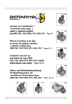
ADDITIONAL STABILIZERS MANUALE DELL’OPERATORE OPERATOR’S MANUAL BEDIENUNGSANLEITUNG 7.84.5013-00 INDICE A MANUALE AVVERTENZE...................................................................... A-1 A.1 A.2 B B.1 B.2 B.3 B.4 B.5 C C.1 C.2 C.3 C.4 C.5 C.6 D D.1 D.2 D.3 D.4 AVVERTENZE GENERALI ............................................................................................................................... A-2 AVVERTENZE PER IL SOLLEVAMENTO E IL TRASPORTO ........................................................................ A-4 MANUALE D’USO .................................................................................. B-1 B.3.1 B.3.2 B.3.3 B.3.4 B.4.1 B.4.2 B.5.1 B.5.2 B.5.3 PREMESSA ...................................................................................................................................................... B-2 IDENTIFICAZIONE ........................................................................................................................................... B-3 DOCUMENTAZIONE E DESCRIZIONE ........................................................................................................... B-4 MARCATURA............................................................................................................................................................................ B-5 CONDIZIONI DI SERVIZIO ....................................................................................................................................................... B-6 COMPONENTI PRINCIPALI ..................................................................................................................................................... B-7 DISPOSITIVI DI SICUREZZA ................................................................................................................................................... B-8 CONTROLLI PRELIMINARI DELLE CONDIZIONI DI LAVORO.................................................................... B-10 RESISTENZA DEL TERRENO ............................................................................................................................................... B-10 CONTROLLI PRELIMINARI .................................................................................................................................................... B-11 OPERARE CON LA TRAVERSA ................................................................................................................... B-12 PROCEDURA DI APERTURA DEGLI STABILIZZATORI....................................................................................................... B-12 PROCEDURA DI CHIUSURA DEGLI STABILIZZATORI........................................................................................................ B-14 CONTROLLI OBBLIGATORI PRIMA DI LASCIARE LA POSTAZIONE DI LAVORO ............................................................ B-16 MANUALE DI MANUTENZIONE ............................................................ C-1 C.2.1 C.6.1 C.6.2 C.6.3 TERMINI DI GARANZIA ................................................................................................................................... C-1 MANUTENZIONE ORDINARIA ........................................................................................................................ C-1 PULIZIA .....................................................................................................................................................................................C-2 MANUTENZIONE PROGRAMMATA................................................................................................................ C-3 MANUTENZIONE STRAORDINARIA............................................................................................................... C-3 INATTIVITÀ....................................................................................................................................................... C-3 MESSA FUORI SERVIZIO................................................................................................................................ C-4 DISINSTALLAZIONE.................................................................................................................................................................C-4 STOCCAGGIO ..........................................................................................................................................................................C-5 SMALTIMENTO.........................................................................................................................................................................C-5 DOCUMENTAZIONE TECNICA ............................................................. D-1 D.1.1 D.1.2 D.1.3 DATI TECNICI................................................................................................................................................... D-3 TIPOLOGIE TRAVERSE...........................................................................................................................................................D-3 DATI TECNICI ...........................................................................................................................................................................D-4 DIMENSIONI D’INGOMBRO.....................................................................................................................................................D-5 SCHEMI IDRAULICI ......................................................................................................................................... D-6 TARGHETTE DI AVVERTIMENTO................................................................................................................... D-9 ANOMALIE ..................................................................................................................................................... D-10 CONTENTS A WARNING MANUAL............................................................................... A-1 A.1 A.2 B B.1 B.2 B.4 B.8 C C.1 C.2 C.3 C.4 C.5 C.6 D D.1 D.2 D.3 D.4 GENERAL WARNINGS .................................................................................................................................... A-2 WARNINGS TO LIFT AND TRANSPORT ........................................................................................................ A-4 OPERATING MANUAL........................................................................... B-1 B.3.1 B.3.2 B.3.3 B.3.4 B.3.5 B.7.6 B.3.6 B.3.7 B.3.8 PREMISE .......................................................................................................................................................... B-2 IDENTIFICATION.............................................................................................................................................. B-3 MARK ........................................................................................................................................................................................ B-5 SERVICE CONDITIONS ........................................................................................................................................................... B-6 MAIN COMPONENTS............................................................................................................................................................... B-7 SAFETY DEVICES.................................................................................................................................................................... B-8 PRELIMINARY VERIFICATION OF WORK CONDITIONS............................................................................ B-10 GROUND RESISTANCE......................................................................................................................................................... B-10 PRELIMINARY CHECKS ........................................................................................................................................................ B-11 OPERATING WITH THE CROSSBEAM......................................................................................................... B-12 PROCEDURE TO OPEN THE STABILIZERS ........................................................................................................................ B-12 PRODEDURE TO CLOSE THE STABILIZERS ...................................................................................................................... B-14 COMPULSORY SAFETY CHECKS BEFORE LEAVING THE WORK PLACE ...................................................................... B-16 MAINTENANCE MANUAL...................................................................... C-1 C.2.1 C.6.1 C.6.2 C.6.3 WARRANTY TERMS ........................................................................................................................................ C-1 ORDINARY MAINTENANCE ............................................................................................................................ C-1 CLEANING ................................................................................................................................................................................C-2 PLANNED MAINTENANCE.............................................................................................................................. C-3 EXTRAORDINARY MAINTENANCE................................................................................................................ C-3 INACTIVITY ...................................................................................................................................................... C-3 TAKING OUT OF SERVICE ............................................................................................................................. C-4 DISASSEMBLY .........................................................................................................................................................................C-4 STORAGE .................................................................................................................................................................................C-5 DISPOSAL.................................................................................................................................................................................C-5 TECHNICAL DOCUMENTS.................................................................... D-1 D.1.1 D.1.2 D.1.2 TECHNICAL SPECIFICATIONS....................................................................................................................... D-3 TYPOLOGIES OF CROSSBEAMS ...........................................................................................................................................D-3 TECHNICAL DATA....................................................................................................................................................................D-4 OVERALL DIMENSIONS ..........................................................................................................................................................D-5 HYDRAULIC DIAGRAMS................................................................................................................................. D-6 WARNING LABELS.......................................................................................................................................... D-9 TROUBLESHOOTING .................................................................................................................................... D-10 INHALT A ANWEISUNGSHANDBUCH ................................................................... A-1 A.1 A.2 B B.1 B.2 B.3 B.4 B.8 C C.1 C.2 C.3 C.4 C.5 C.6 D D.1 D.2 D.3 D.4 ALLGEMEINE HINWEISE ................................................................................................................................ A-2 WARNUNGEN FÜR TRANSPORT UND ANHEBEN ....................................................................................... A-4 BEDIENUNGSHANDBUCH .................................................................... B-1 B.3.1 B.3.2 B.3.3 B.3.4 B.3.5 B.7.6 B.3.6 B.3.7 B.3.8 VORWORT........................................................................................................................................................ B-2 KENNDATEN .................................................................................................................................................... B-3 DOKUMENTATION UND BESCHREIBUNG .................................................................................................... B-4 KENNZEICHNUNG ................................................................................................................................................................... B-5 DIENSTBEDINGUNGEN........................................................................................................................................................... B-6 HAUPTKOMPONENTEN .......................................................................................................................................................... B-7 SICHERHEITSEINRICHTUNGEN ............................................................................................................................................ B-8 VORABKONTROLLEN DER ARBEITSBEDINGUNGEN............................................................................... B-10 WIDERSTAND DES GELÄNDES ........................................................................................................................................... B-10 ALLGEMEINE VORABKONTROLLEN.................................................................................................................................... B-11 BEDIENEN DER TRAVERSE ......................................................................................................................... B-12 ÖFFNUNGSVERFAHREN DER ABSTÜTZUNGEN ............................................................................................................... B-12 SCHLIESSUNGSVERFAHREN DER ABSTÜTZUNGEN ....................................................................................................... B-14 VERBINDLICHE KONTROLLE VOR DEM VERLASSEN DES ARBEITZPLATZES .............................................................. B-16 WARTUNGSHANDBUCH....................................................................... C-1 C.2.1 C.6.1 C.6.2 C.6.3 GARANTIEBESTIMMUNGEN .......................................................................................................................... C-1 ORDENTLICHE WARTUNG ............................................................................................................................. C-1 REINIGUNG ..............................................................................................................................................................................C-2 GEPLANTE WARTUNG ................................................................................................................................... C-3 AUSSERPLANMÄSSIGE WARTUNG.............................................................................................................. C-3 STILLSTAND .................................................................................................................................................... C-3 AUßER BETRIEB SETZEN .............................................................................................................................. C-4 DEMONTAGE ...........................................................................................................................................................................C-4 LAGERUNG ..............................................................................................................................................................................C-5 ENTSORGUNG.........................................................................................................................................................................C-5 TECHNISCHE DOKUMENTATION ........................................................ D-1 D.1.1 D.1.2 D.1.2 TECHNISCHE DATEN...................................................................................................................................... D-3 TYPOLOGIEN VON ZUSATZABSTÜTZUNGEN ......................................................................................................................D-3 TECHNISCHE DATEN ..............................................................................................................................................................D-4 GESAMTABMESSUNGEN .......................................................................................................................................................D-5 HYDRAULIKSCHEMA...................................................................................................................................... D-6 WARNUNGSSCHILDE ..................................................................................................................................... D-9 STÖRUNGEN.................................................................................................................................................. D-10 INDICE DELLE TABELLE INDEX OF TABLES VERZEICHNIS DER TABELLEN Tab. B-1: Condizioni di servizio - Service conditions - Dienstbedingungen............................................................................. B-6 Tab. B-2: Portata del terreno - Bearing capacity of the soils - Belastbarkeit des Bodens ..................................................... B-10 A MANUALE AVVERTENZE A WARNING MANUAL A ANWEISUNGSHANDBUCH A-1 A.1 AVVERTENZE GENERALI A.1 GENERAL WARNINGS A.1 ALLGEMEINE HINWEISE Le gru che lavorano con stabilizzatori supplementari presentano rischi specifici che vengono di seguito elencati: Pericoli di schiacciamento e cesoiamento degli arti superiori tra le aste. Pericoli di schiacciamento degli arti inferiori durante le operazioni di apertura dei cilindri stabilizzatori e di chiusura delle aste. Pericoli legati alla non perfetta stabilizzazione della macchina. There are specific hazards for cranes operating with supplementary crossbeam, as listed below: Crushing and cutting hazard for upper limbs between rods. Crushing hazard for lower limbs during opening of stabiliser cylinders and closing of rods. Hazards due to imperfect stabilisation of the machine. Die Kräne, die mit Zusatzabstützungen arbeiten, weisen spezifische Gefahren auf, die nachstehend aufgeführt werden: Quetsch- und Schergefahr der oberen Gliedmaßen zwischen den Stangen. Quetschgefahr der unteren Gliedmaßen während der Öffnung der Abstützzylinder und Schließen der Stangen. Gefahren in Verbindung mit der nicht perfekten Stabilisierung der Maschine. AVVERTENZE WARNINGS WARNUNGEN - Non sostare in prossimità delle aste stabilizzatrici idrauliche in uscita in direzione di apertura. - Keep all personnel away from the hydraulic stabiliser rods during opening. - Der Aufenthalt in der Nähe der ausfahrenden hydraulischen Abstützstangen in Öffnungsrichtung ist verboten. - Non posizionare il piede o arti in genere sotto il piattello del cilindro stabilizzatore in fase di stabilizzazione gru. - Do NOT place feet or limbs under the stabiliser cylinder plate during crane stabilisation. - Den Fuß oder Gliedmaßen während der Stabilisierung des Krans nicht unter die Scheibe des Abstützzylinders bringen. - Non interporre mai gli arti tra il cilindro stabilizzatore e l’autocarro in fase di chiusura automatica idraulica delle aste stabilizzatrici. - Do NOT place limbs between the stabiliser cylinder and truck during automatic hydraulic closing of the stabiliser rods. - Während der automatischen hydraulischen Schließung der Abstützstangen auf keinen Fall die Gliedmaßen zwischen Abstützzylinder und Lkw bringen. A-2 - Attenzione a non urtare contro gli stabilizzatori durante l’operazione di stabilizzazione gru. - Do NOT bang into the stabilisers when the crane is being stabilised. - Während der Stabilisierung des Krans nicht gegen die Stützen stoßen. - Non inserire gli arti superiori per nessun motivo a gru operativa in prossimità dell’ingresso aste stabilizzatrici supplementari nel longherone. - When the crane is in operation do NOT place upper limbs near the supplementary stabiliser rod entry point in the beam. - Während des Kranbetriebs unter keinen Umständen die oberen Gliedmaßen in die Nähe des Einzugs der zusätzlichen Abstützstangen in den Längsträger bringen. - Per quanto riguarda gli altri rischi fare riferimento al manuale uso e manutenzione proprio degli stabilizzatori supplementari. - For other hazards refer to the user and maintenance manual for the supplementary stabilisers. - Was die anderen Gefahren betrifft, wird das Bedienungsund Wartungshandbuch der Zusatzabstützungen verwiesen. A-3 A.2 AVVERTENZE PER IL SOLLEVAMENTO E IL TRASPORTO A.2 WARNINGS TO LIFT AND TRANSPORT A.2 WARNUNGEN FÜR TRANSPORT UND ANHEBEN Gli stabilizzatori supplementari, quando non installati, devono essere movimentati in sicurezza per evitare cadute ed urti con cose e persone. Il trasportatore durante lo spostamento deve rispettare le seguenti istruzioni: The additional stabilizers when they are not installed, must be handled safely to avoid falls and collisions with things and people. The carrier while moving, must respect the following instructions: Wenn die Zusatzabstützungen nicht installiert sind, müssen sie gefahrlos transportiert werden, um Fälle und Zusammenstöße mit Gegenstände und Personen zu vermeiden. Während des Transports, muss der Beförderer diese Anweisungen befolgen: 1. Il trasportatore è il responsabile degli stabilizzatori supplementari e pertanto deve essere qualificato. 1. The carrier is responsible for additional stabilizers and must be qualified. 1. Der Beförderer ist verantwortlich für die Zusatzabstützungen, daher muss er qualifiziert sein. 2. Utilizzare un mezzo di trasporto o sollevamento di portata adeguata. 2. Use a means of transport or lifting of suitable capacity. 3. Sollevare gli stabilizzatori supplementari tramite carrello elevatore su pallet, oppure con gru e funi di portata adeguata: prestare particolare attenzione al bilanciamento del carico durante il suo sollevamento. 3. Raise the additional stabilizers using a forklift on pallet or a crane with ropes of adequate capacity: pay special attention to load balancing during his lifting. 2. Ein Transportmittel oder eine Hebevorrichtung mit angemessener Tragkraft verwenden. 3. Die Zusatzabstützungen mit Gabelstapler auf Palette oder mit Kran und Seil mit ausreichender Tragfähigkeit anheben. 4. Durante Il trasporto per terra o per mare, fissare la traversa o il suo contenitore al mezzo di trasporto (cassone, container, stiva, ecc.). La macchina deve essere protetta dagli agenti atmosferici e mai disimballata. 4. During the transport by land and sea, fix the crossbeam or its container to the means of transport (body, container, hold, etc.). Protect the machine properly from atmospheric agents. Never unpack the crane. A-4 4. Während des Transports zu Wasser und zu Lande, die Traverse oder den Behälter am Transportmittel befestigen (Pritsche, Container, Kielraum, usw.). Die Maschine muss vor Wetterungseinflüssen geschützt und nie ausgepackt werden. B MANUALE D’USO B OPERATING MANUAL B BEDIENUNGSHANDBUCH B-1 B.1 PREMESSA B.1 PREMISE B.1 VORWORT Caro Cliente, Dear Customer, Verehrter Kunde, La ringraziamo per aver scelto un nostro prodotto. Noi abbiamo fatto tutto il possibile per consegnarle un prodotto ottimo e sicuro. Per garantire che la Sua gru operi in modo sicuro la preghiamo di osservare le seguenti regole: Thank you for buying our product. We have done everything we can to supply you with an excellent and safe product. Please follow the instructions given below to ensure that your crane operates safely: Wir danken Ihnen für die Wahl unseres Produkts. Wir haben unser Möglichstes getan, um Ihnen ein ausgezeichnetes und sicheres Produkt zu liefern. Um zu garantieren, dass Ihr Kran sicher arbeitet, bitten wir Sie, sich an die folgenden Regeln zu halten: - Osservare le avvertenze e le istruzioni d’uso e manutenzione. - Follow the warnings as well user and maintenance instructions. - Befolgen Sie unbedingt die Hinweise und Bedienungs- und Wartungsanleitungen. - Mantenere la sicurezza e l’efficienza della macchina con una manutenzione accurata. - Perform routine maintenance to keep your machine efficient and safe. - Bewahren Sie die Sicherheit und die Funktionstüchtigkeit der Maschine durch sorgfältige Wartung. - Mantenere la macchina pulita. Lo sporco aumenta l’usura dei cilindri. Le perdite di olio o di altri lubrificanti sono la maggiore sorgente di incidenti. - Keep the machine clean. Dirt increases wear of the cylinders. Leaks of oil and other fluids are the main cause of accidents. - Halten Sie die Maschine sauber. Schmutz erhöht den Verschleiß der Zylinder. Das Austreten von Öl und anderen Schmiermitteln ist die häufigste Unfallursache. - Seguire le manuale. - Follow the instructions in this manual. - Befolgen Sie die in diesem Handbuch enthaltenen Anleitungen. - Portare sempre assieme alla macchina questo manuale il quale deve essere custodito in un luogo protetto e di facile accesso al solo operatore. - Always keep this manual in a safe place with the machine so that it is accessible to the operator at all times. - Dieses Handbuch muss sich immer mit der Maschine befinden, damit es vom Kranführer zu jeder Zeit eingesehen werden kann. - In caso di vendita il nuovo proprietario è tenuto a richiedere una copia aggiornata del presente manuale. - If the machine is sold the new owner must request an updated version of this manual. - Wird die Maschine weiterverkauft, muss der neue Eigentümer eine aktualisierte Kopie des vorliegenden Handbuchs anfordern. - In caso di danneggiamento, anche parziale, o perdita del seguente Manuale rivolgersi ad una officina autorizzata. - Refer to an authorised assistance centre in the event of damage to, even partial, or loss of this manual. - Bei teilweiser Beschädigung oder Verlust dieses Handbuchs wenden Sie sich bitte an eine autorisierte Werkstatt. Il presente manuale Avvertenze Uso e Manutenzione è relativo solo agli stabilizzatori supplementari, in quanto non copre l’abbinamento col veicolo. Il manuale dell’Installazione completo viene rilasciato dall’installatore, il quale provvederà alla marcatura CE dell’insieme. This Warnings, Use and Maintenance Manual is for the additional stabilizers only and does not refer to the truck. The complete installation manual is released by the installer who is responsible for applying the EC mark to the assembly. Das vorliegende Anweisungs-, Bedienungs- und Wartungshandbuch bezieht sich nur auf die Zusatzabstützungen und deckt nicht die Kombination mit dem Fahrzeug ab. Das komplette Installationshandbuch wird vom Installateur verfasst, der auch die EGKennzeichnung der ganzen Maschine vornimmt. Distinti saluti Yours sincerely Mit freundlichen Grüßen istruzioni di questo B-2 B.2 IDENTIFICAZIONE B.2 IDENTIFICATION B.2 KENNDATEN FABBRICANTE MANUFACTURER HERSTELLER AMCO VEBA SRL Unico Socio AMCO VEBA SRL One sole share holder AMCO VEBA SRL Alleiniger Gesellschafter Via Einstein 4, 42028 POVIGLIO (RE) ITALY Via Einstein 4, 42028 POVIGLIO (RE) ITALY Via Einstein 4, 42028 POVIGLIO (RE) ITALY DATI IDENTIFICATIVI IDENTIFICATION DATA IDENTIFIKATIONSDATEN Modello: Model: Modell: Matricola: Serial number: Kennnummer: NORMA DI PROGETTO DESIGN STANDARD ENTWURFSNORM DIN 15018 DIN 15018 DIN 15018 B-3 B.3 DOCUMENTAZIONE E DESCRIZIONE B.3 DESCRIPTION AND DOCUMENTATION B.3 DOKUMENTATION UND BESCHREIBUNG Le traverse stabilizzatrici sono progettate esclusivamente per essere installate su veicoli assieme a gru dotate di stabilizzatori propri. Esse contribuiscono ad aumentare la stabilità del veicolo durante le operazioni di sollevamento. The additional stabilizers are exclusively designed to be installed on vehicles with cranes equipped with own stabilizers. They help to increase the stability of the vehicle during lifting operations. Die Zusatzabstützungen sind ausschließlich geplant, um auf Fahrzeuge zusammen mit Kränen mit Abstützungen installiert zu werden. Sie helfen mit, die Stabilität des Fahrzeuges während der Hebetätigkeit zu erhöhen. Il montaggio deve essere eseguito a regola d’arte da un’officina autorizzata, secondo le istruzioni contenute nel Manuale dell’Installatore rilasciato dal fabbricante e le specifiche di allestimento specifiche del veicolo. Assembly must be performed by an authorised assistance centre in accordance with the instructions in the installer manual released by the manufacturer and the vehicle setup specifications. Alla consegna della macchina l’operatore è tenuto a ricevere da parte dell’installatore un addestramento adeguato su tutte le funzioni secondo la norma ISO 9926-1. The installer must provide training for operators concerning all aspects of functioning at the moment of machine delivery in accordance with ISO 9926-1. Die Montage muss von einer autorisierten Werkstatt fachgerecht und gemäß den Anleitungen in dem vom Hersteller verfassten Installationshandbuch, sowie unter Befolgung der Ausrüstungsspezifikationen des Fahrzeugs durchgeführt werden. Bei Auslieferung der Maschine muss der Bediener vom Installateur eine angemessene Schulung gemäß ISO 9926-1 über alle Funktionen erhalten. L’installatore deve inoltre consegnare al cliente finale i seguenti documenti debitamente compilati e sottoscritti: The installer must give the final customer the following documents, completed and signed as necessary: Der Installateur muss dem Endkunden die folgenden, vorschriftsmäßig ausgefüllten und unterzeichneten Unterlagen aushändigen: - Dichiarazione CE (solo per paesi CE); - Manuale dell’installatore; - Manuale dell’operatore; - EC declaration (only EC countries); - Installer manual; - Operator’s manual; - EG-Erklärung (nur für EG-Länder); - Bauanleitung; - Bedienungsanleitung; Il proprietario è responsabile per l’esecuzione delle ispezioni ricorrenti previste dalla legge. The owner is responsible for the routine inspections required by law. Der Eigentümer ist verantwortlich für die Ausführung der gesetzlich vorgeschriebenen Inspektionen. B-4 B.3.1 MARCATURA B.3.1 MARK B.3.1 KENNZEICHNUNG Su ogni traversa supplementare è applicata una targhetta indelebile che riporta le seguenti informazioni: An indelible plate containing the following information ist fitted on every supplementary stabilizer: Ein unlöschbares Schild mit folgenden Angaben ist auf jeder Zusatzabstützung angebracht: - nome e indirizzo del fabbricante - marchio CE (solo per macchine CE) - modello - numero di matricola - anno di costruzione - portata massima - massa totale (kg) - name and address of manufacturer - CE mark (only for EC machines) - model - serial number - year of manufacture - maximum capacity - total weight (kg) - Name und Adresse des Herstellers - CE-Zeichen (nur für EG-Maschinen) - Modell - Kennnummer - Baujahr - Maximale Belastung - Gesamtgewicht (kg) CE La targhetta è rivettata a lato della traversa portante. NO CE The plate is riveted to the bearing crossbeam side. B-5 Das Typenschild ist auf der Seite des tragenden Traverse vernietet. B.3.2 CONDIZIONI DI SERVIZIO B.3.2 SERVICE CONDITIONS B.3.2 DIENSTBEDINGUNGEN La macchina è stata progettata per lavorare alle seguenti condizioni: The machine is designed to operate under the following conditions: Die Maschine ist für den Einsatz unter folgenden Bedingungen ausgelegt: Tab. B-1: Condizioni di servizio - Service conditions - Dienstbedingungen DESCRIZIONE DESCRIPTION BESCHREIBUNG RANGE BEREICH Temperatura ambiente Environmental temperature Umgebungstemperatur -10°C 40°C Temperatura olio idraulico Hydraulic oil temperature Hydrauliköltemperatur -10°C 80°C Resistenza del suolo Ground resistance Belastbarkeit von Boden Portata del suolo > pressione max piedi stabilizzatori Ground bearing capacity > max stabilizer feet pression Belastbarkeit von Boden > Max. Abstützfüße-Druck Condizioni atmosferiche Weather Wetter Vietato l’uso durante temporali Do NOT use during storms Der Gebrauch bei Gewitter ist verboten Ambienti di lavoro vietati Forbidden working environments Verbotene Arbeitsumgebungen Se tali condizioni non sono tutte verificate, l’operatore deve interrompere immediatamente le operazioni. Ambiente marino, ambienti a rischio esplosione Marine and explosive environments Maritime und explosionsgefährdete Umgebungen If all these conditions do not exist, stop work immediately. B-6 Falls alle diese Bedingungen nicht eingehalten werden, muß der Kranführer die Arbeiten sofort abbrechen. B.3.3 COMPONENTI PRINCIPALI B.3.3 MAIN COMPONENTS B.3.3 HAUPTKOMPONENTEN Si elencano a seguire i componenti principali delle traverse supplementari: A list of the main components of additional stabilizers is given below: Nachstehend werden die Hauptkomponenten der Zusatzabstützungen aufgezählt: 1) 2) 3) 4) 5) 6) 7) 8) 1) 2) 3) 4) 5) 6) 7) 8) 1) 2) 3) 4) 5) 6) 7) 8) Traversa Asta stabilizzatrice Cilindro stabilizzatore Piattello di base Valvola di blocco Cilindro estensione aste stab. Perno di bloccaggio Tubi di collegamento Crossbeam Stabilizer beam Stabilizer cylinder Footplate Block valve Stabilizer extension cylinder Lock pin Connecting pipes B-7 Traverse Stützstange Stützzylinder Füßplatte Sperrventil Stangenschubzylinder Sperrbolzen Verbindungsrohre B.3.4 DISPOSITIVI DI SICUREZZA B.3.4 SAFETY DEVICES B.3.4 SICHERHEITSEINRICHTUNGEN La sicurezza di funzionamento degli stabilizzatori supplementari è legata all’efficienza dei sistemi di sicurezza del veicolo su cui è montata; questo dev’essere dotato di dispositivo di acustico-luminoso che segnali che la gru è attiva. Le traverse supplementari sono inoltre dotate di propri dispositivi di sicurezza, elencati di seguito: The operating safety of additional stabilizers is linked to the efficiency of safety devices installed on the vehicle: this has to be fitted with a visual and acoustic device to signal the running of the crane. The additional crossbeams are furthermore equipped with the following safety devices: Die Bedienungssicherheit der Zusatzabstützungen ist mit der Effizienz der Sicherheitseinrichtungen des Fahrzeugs verbunden. Das Fahrzeug muss mit einer optischen und akustischen Signaleinrichtung ausgestattet werden, die warnt, dass der Kran in Betrieb ist. Außerdem sind die Zusatzabstützungen mit den folgenden eigenen Sicherhetseinrichtungen ausgestattet: VALVOLE DI BLOCCO Tutte le traverse supplementari sono fornite di valvole di blocco a singolo effetto sui cilindri stabilizzatori: esse impediscono, in caso di calo di pressione nel circuito oleodinamico, il cedimento accidentale dei cilindri stessi e la conseguente perdita improvvisa di stabilità del veicolo. Le valvole possono essere fornite in versione manuale con leva di sblocco oppure in versione pilotata a sblocco idraulico. I modelli di traverse più grandi sono dotati di valvole di blocco doppie. BLOCK VALVES All additional stabilizers are equipped with single-acting pilot check valves on stabilizer cylinders: these valves prevent, in case of drop of pressure in the hydraulic system, the accidental yielding of cylinders and the subsequent sudden loss of stability of the vehicle. The valves can be supplied in handoperated version with release lever or in pilot-operated version with hydraulic release. The larger models of crossbeams are fitted with doble-acting pilot check valves. SPERRVENTILE Alle Zusatzabstützungen sind mit einzel-entsperrbaren Rückschlagventilen auf den Stützzylindern ausgestattet: diese Ventile verhindern bei Druckabfall in der Hydraulikanlage das zufällige Nachgeben der Zylinder und den anschließenden plötzlichen Stabilitätsverlust des Fahrzeugs. Die Ventile können in handbetätigter Version mit Hebel oder in vorgesteuerter Version mit hydr. Entriegelung geliefert werden. Die größeren Modelle von Zusatzabstützungen sind mit doppelentsperrbaren Rückschlagventilen ausgerüstet. ARRESTO SEMIAUTOMATICO TRAVE CON LEVA SEMIAUTOMATIC BEAM LOCK WITH LEVER HALBAUTOMATISCHES STANGENSPERRGETRIEBE MIT HEBEL Ha la funzione di bloccare automaticamente le aste stabilizzatrici in posizione di completa apertura e completa chiusura quando la leva è rivolta verso il basso. Its purpose is to lock automatically the stabilizer rods in their fully opened and closed position, when the lever is turned downward. Aufgabe dieser Vorrichtung ist es, automatisch die Stützstangen in Öffnungsund Schließstellung zu blockieren, wenn der Hebel nach unten gedreht ist. B-8 ARRESTO TRAVE AUTOMATICO A MOLLA AUTOMATIC ROD LOCKS WITH SPRING (NO AA CRANE) AUTOMATISCHE STANGENSPERRGETRIEBE MIT FEDER Ha la funzione di bloccare automaticamente le aste stabilizzatrici in posizione di completa chiusura. Its purpose is to lock automatically the stabilizer beams in their fully closed position. Aufgabe dieser Vorrichtung ist es, automatisch die Stützstangen in Schließstellung zu blockieren. Il non perfetto bloccaggio delle aste in posizione retratta durante il trasporto può causare gravi rischi a cose e persone. Failure to lock the retracted beams correctly when transporting the machine may cause damage to property and injury to people. Wenn die Stangen während des Transports nicht einwandfrei in eingezogener Position blockiert werden, können Personen und Sachen ernsthaft gefährdet werden. DISPOSITIVO DI SEGNALAZIONE CHIUSURA ASTE STABILIZZATRICI DEVICE SIGNALLING THE CLOSING OF THE STABILIZER BEAMS WARNVORRICHTUNG VON SCHLUSS DER STÜTZSTANGEN Il dispositivo è costituito da due microinterruttori a contatto connessi con una spia bicolore installata in cabina: The device is formed by two contact micro connected with a two-color light installed in the cab (2): Die Vorrichtung besteht aus zwei Kontaktmikroschaltern, die mit einer zweifarbigen in Fahrerhaus installierten Luechte angeordneten sind: 1 2 Spia rossa: indica che una o più aste stabilizzatrici non sono correttamente chiuse; Spia verde: indica che tutte le aste sono correttamente chiuse. Red light: indicates that one or more stabilizer extensions are not closed correctly; Green light: indicates that all stabilizer extensions are correctly closed. Rote Leuchte: zeigt, daß eine oder mehr Stützen unkorrekt geschlossen sind; Grüne Leuchte: zeigt, daß alle Stützen korrekt geschlossen sind. L'operatore non può spostare il veicolo se la spia è rossa. The operator can not move the vehicle if the warning light is red. Der Bediener kann nicht abfahren, wenn die Kontrollampe rot ist. B-9 B.4 CONTROLLI PRELIMINARI DELLE CONDIZIONI DI LAVORO B.4 PRELIMINARY VERIFICATION OF WORK CONDITIONS B.4 VORABKONTROLLEN DER ARBEITSBEDINGUNGEN B.4.1 RESISTENZA DEL TERRENO B.4.1 GROUND RESISTANCE B.4.1 WIDERSTAND DES GELÄNDES Prima di stabilizzare la macchina è necessario verificare che il suolo o qualsiasi altro appoggio, possa sostenere la pressione causata dagli stabilizzatori. Se questa pressione, infatti, supera quella ammissibile, bisogna aumentare la superficie d’appoggio per scongiurare il rischio di perdita di stabilità. Before stabilising the machine check that the ground or support surface is capable of withstanding the pressure caused by the stabilisers. If this pressure exceeds the maximum permitted value, increase the area of the support surface to avoid loss of stability. Vor der Stabilisierung der Maschine muss überprüft werden, ob der Boden oder jede sonstige Auflage den von den Stützen erzeugten Druck aushalten kann. Wenn dieser Druck den zulässigen Wert übersteigt, muss die Auflagefläche vergrößert werden, um die Gefahr eines Stabilitätsverlustes zu vermeiden. Se si utilizzano piastre supplementari per aumentare la superficie di appoggio è necessario verificare che queste non cedano sotto carico. Check that any supplementary sheets used to increase the area of the stabiliser support surface are able to support the load. Wenn man zusätzliche Platten verwendet, um die Auflagefläche der Stützen zu vergrößern, muss es sichergestellt werden, dass diese nicht unter der Last nachgeben. In caso di stabilizzazione su terreno, la superficie di appoggio minima può essere calcolata in base alla reazione degli stabilizzatori e alla portata del terreno: la reazione massima sugli stabilizzatori è riportata nell’allegato §D.1.2. Valori indicativi per la portata dei terreni sono riportati in Tab. B-2. If the machine is used on open ground the min. support area can be calculated on the basis of the reaction of the stabilisers and the bearing capacity of the ground. The max. reaction force of stabilisers is shown in §D.1.2. Indicative values for the Bearing capacity of the ground are shown in Tab. B-2. Bei Stabilisierung auf dem Boden kann die Mindestauflagefläche anhand der Reaktion der Stützen und der Belastbarkeit des Bodens berechnet werden: die max. Reaktion an den Stützen ist in §D.1.1 angezeigt. Die Richtwerte für die Belastbarkeit sind in Tab. B-2 aufgeführt. Tab. B-2: Portata del terreno - Bearing capacity of the soils - Belastbarkeit des Bodens PORTATA BEARING CAPACITY BELASTBARKEIT [daN/cm2] TIPO DI TERRENO SOIL TYPE BODEN TYP Terreno di riporto, non costipato artificialmente Fill soil, artificially unpacked Aufgeschütteter, nicht künstlich gestampfter Boden Terreni naturali, evidentemente vergini (fango, torba, terreno paludoso) Natural, clearly virgin soils (mud, peat, marsh soil) Natürliche, klar unberührte Böden (Schlamm, Torf, Sumpfboden) Terreni non coerenti, ma compatti (sabbia fine e media) Not coherent, but compact soils (fine and medium sand) Nicht bindige, sondern feste Böden (Fein- und Mittelsand) Sabbia grossa e ghiaia Coarse sand and gravel Grober Sand und Kies Terreni coerenti: Coherent soils: Bindige Boden: - pastoso - doughy - teigiger - soffice - soft - weicher - rigido - rigid - rigid - semi-solido - half-solid - halb-fester - solido - solid - fester - roccia - rock - Gestein - roccia massiccia - solid rock - massives Gestein B-10 da 0.0 a 1.0 from 0.0 to 1.0 von 0.0 bis 1.0 0 1.5 2.0 0 0.4 1.0 2 4 15 30 Detta Rmax [daN] la massima forza del cilindro stabilizzatore e Pamm [daN/cm2] la pressione massima ammissibile del terreno, è possibile calcolare con la seguente formula l’area minima (A) della superficie d’appoggio Given Rmax [daN] the maximum force of the stabiliser cylinder and Pamm 2 [daN/cm ] the maximum pressure permitted on the ground, the following formula can be used to calculate the minimum area (A) for the support surface A R max Pamm Das Mindestflächenmaß (A) der Auflagefläche kann mit folgender Formel berechnet werden. Rmax [daN] ist die maximale Kraft des Abstützzylinders und Pamm [daN/cm2] der maximal zulässige Bodendruck. [cm2] Per evitare problemi di perdita di stabilità è fondamentale inoltre non appoggiare gli stabilizzatori in prossimità di scarichi, tombini, fognature, pozzetti, fossi e, in generale, su qualsiasi superficie di cui non si è certi che possa reggere la forza massima degli stabilizzatori. To avoid loss of stability do not place the stabilisers near drains, manholes, wells, ditches and in general on any surface unable to support, with certainty, the maximum force of the stabilisers. Um einen Stabilitätsverlust zu vermeiden, muss es unbedingt darauf geachtet werden, dass die Stützen nicht in der Nähe von Abläufen, Gullys, Kanalisationen, Brunnenschächten, Gräben und generell auf keinem Untergrund aufgestellt werden, von dem man nicht sicher ist, dass er die maximale Krafteinwirkung der Stützen aushalten kann. B.4.2 CONTROLLI PRELIMINARI B.4.2 PRELIMINARY CHECKS B.4.2 ALLGEMEINE VORABKONTROLLEN Before using the crane check: Vor Benutzung des Krans muss der Kranführer Folgendes kontrollieren: Prima di utilizzare la l’operatore deve verificare: macchina - L’integrità strutturale e dei dispositivi di sicurezza. - The integrity of the structure and safety device. - die Unversehrtheit der Struktur und der Sicherheitseinrichtungen. - L’assenza di parti aggiunte all’apparecchio non verificate o non ammesse per l’uso previsto. - There are no parts on the equipment which have not been checked or are not permitted. - das Fehlen von nachträglich angebrachten Teilen, die nicht überprüft wurden oder nicht für die vorgesehene Verwendung zulässig sind. - L’efficienza del sistema idraulico, dei raccordi, delle valvole, dei dispositivi di sicurezza, l’assenza di perdite d’olio. - Efficiency of the hydraulic system, fittings, valves and safety devices. Check there are no oil leaks. - die Funktionstüchtigkeit des Hydrauliksystems, der Anschlüsse, der Ventile, der Sicherheitseinrichtungen, Fehlen von Ölleckagen. - Il perfetto stato di manutenzione e serraggio di viti, bulloni e perni. - Perfect status of maintenance and tightness of screws, nuts, bolts and pins. - die perfekte Wartung und Anzug von Schrauben, Mutterschrauben und Bolzen. - La presenza e l’integrità di tutte le targhette applicati. - Presence and integrity of all warning labels. - das Vorhandensein und die Unversehrtheit aller angebrachten Schilde. - L’efficienza del sistema di controllo stabilità (solo per gru CE): verificare che i led sui proximity installati sul basamento e sugli stabilizatori supplementari siano accesi quando la gru è stabilizzata correttamente. - Efficiency of the stability control system (only for EC cranes): check that the leds of proximities mounted on crane base and on additional stabilizers are ON when the crane is correctly stabilized. - die Funktionstüchtigkeit des Stabilitätskontrollsystems (nur für EG Kräne): überprüfen, dass die die Leuchtdioden der Näherungssensoren (auf Kransockel und Zusatzabstützungen) leuchtend sind, wenn der Kran korrekt stabilisiert ist. B-11 B.5 OPERARE CON LA TRAVERSA B.5 OPERATING WITH THE CROSSBEAM B.5 BEDIENEN DER TRAVERSE B.5.1 PROCEDURA DI APERTURA DEGLI STABILIZZATORI B.5.1 PROCEDURE TO OPEN THE STABILIZERS B.5.1 ÖFFNUNGSVERFAHREN DER ABSTÜTZUNGEN I cilindri stabilizzatori supplementari sono comandati dalla leve stabilizzatori gru, e vengono attivati contemporaneamente a quelli standard. Pertanto si mostrerà di seguito solo un'integrazione alla procedura relativa alla stabilizzazione standard della gru descritta. The additional stabilizer cylinders are controlled by the crane stabilizer levers, and they are activated at the same time with the standard stabilizers. Therefore we show only an addendum of the standard stabilizing procedure of the crane. Die Zusatzabstützbeine werden von Kranabstützhebeln gesteuert, und werden gleichzeitig mit den Standardabstützbeine betätigt. Daher zeigt man nur eine Ergänzung des Standardabstützverfahrens des Krans. Si ricorda che è obbligatorio agire sempre sui comandi che si trovano sul lato ove si opera. Remember that you must always use the controls on the side on which you are operating the crane. Wir weisen ausdrücklich hin, dass der Steuerhebel immer auf der Seite zu benutzen ist, auf der auch die Kranbewegung erfolgt. Eseguire le seguenti operazioni: Execute the following procedure: Das folgende Verfahren ausführen: 1) Bloccare le ruote con apposite zeppe. 1) Block the wheels with suitable wedges. 1) Die Räder mit den entsprechenden Keilen blockieren. 2) Disattivare i dispositivi di bloccaggio delle aste stabilizzatrici. 2) Disable the extension locks of the stabilizer beams. 2) Die ausschalten 3) Estrarrre l'asta di qualche centimetro, attivare il dispositivo di bloccaggio dell'asta. 3) Extend the beam by few centimeters, activate the extension locks. 3) Die Stange einige Zentimeter ausfahren, die Sperrgetriebe einschalten. B-12 Stangensperrgetriebe 4) Estendere completamente le aste stabilizzatrici supplementari verificando che il perno arresto trave sia perfettamente inserito nell'asta. 4) Extend fully the supplementary stabilizer rods: check that the rod lock pin are perfectly inserted in the beam. 4) Die Zusatzabstützstangen vollständig ausfahren: überprüfen dass der Sperrbolzen ordnungsgemäß in der Stange eingesetzt ist. 5) Aprire la valvola di blocco (se con leva), estendere i cilindri stabilizzatori senza scaricare totalmente le sospensioni dell’autocarro. 5) Unlock the check valve (if with lever), open the stabilizer cylinders without fully discharging the truck’s suspensions. 5) Das Sperrventil offnen (wenn mit Hebel), die Stützzylinder ausfahren ohne dabei die Fahrzeugfederung völlig zu entlasten. 6) Chiudere la valvola di blocco (se con leva). 6) Lock the check valve (if with lever). 6) Das Sperrventil schließen (wenn mit Hebel). È possibile lavorare con la gru solamente quando tutti gli stabilizzatori sono piazzati correttamente. Working with the crane is allowed only when all stabilizers are deployed correctly. Die Arbeit mit dem Kran ist nur dann erlaubt, wenn alle Abstützungen korrekt angeordnet sind. B-13 B.5.2 PROCEDURA DI CHIUSURA DEGLI STABILIZZATORI B.5.2 PRODEDURE TO CLOSE THE STABILIZERS B.5.2 SCHLIESSUNGSVERFAHREN DER ABSTÜTZUNGEN Gli stabilizzatori supplementari possono essere chiusi esclusivamente dopo la chiusura della gru in posizione di trasporto. The additional stabilizers and can be closed exclusively when the crane is closed in transport position. Die Zusatzabstützbeine können nur eingefahren werden, nachdem der Kran in Transportposition geschlossen worden ist. Si ricorda che è obbligatorio agire sempre sui comandi che si trovano sul lato ove si opera. Remember that you must always use the controls on the side on which you are operating the crane. Wir weisen ausdrücklich hin, dass der Steuerhebel immer auf der Seite zu benutzen ist, auf der auch die Kranbewegung erfolgt. Eseguire le seguenti operazioni: Carry out the follow operations: Das folgende Verfahren ausführen: 1) Aprire la valvola di blocco (se con leva) 1) Unlock the check valve (if with lever) 1) Das Sperrventil öffnen (wenn mit Hebel) 2) Chiudere i cilindri stabilizzatori, chiudere la valvola di blocco (se con leva). 2) Close fully the stabilizer cylinders, lock the check valve (if with lever). 2) Die Stützzylinder einfahren, das Sperrventil schließen (wenn mit Hebel). 3) Disattivare il dispositivo di bloccaggio delle aste stabilizzatrici. 3) Disable the extension locks of the stabilizer beams. 3) Die Stangensperrgetriebe schalten. B-14 aus- 4) Far rientrare l'asta di qualche centimetro, attivare il dispositivo di bloccaggio dell'asta supplementare. 4) Retract the beam by few centimeters, activate the extension locks. 4) Die Stützstange einige Zentimeter einfahren, die Sperrgetriebe einschalten. 5) Far rientrare completamente le aste stabilizzatrici verificando che il perno arresto trave sia perfettamente inserito nell'asta. 5) Retract fully the stabilizer beams: check that the beam lock pin are perfectly inserted in the beam. 5) Die Stützstangen vollständig ausfahren: überprüfen dass der Sperrbolzen ordnungsgemäß in der Stange eingesetzt ist (F) 6) Rimuovere le zeppe. 6) Remove the wedges. 6) Die Keilen entfernen. È vietato movimentare l’autocarro se tutti gli stabilizzatori non sono chiusi e bloccati correttamente. It is forbidden to move the truck if all stabilizers are not closed and not locked correctly. Das ist verboten, das Fahrzeug zu bewegen wenn nicht alle Abstützungen richtig geschlossen und blockiert sind. B-15 B.5.3 CONTROLLI OBBLIGATORI PRIMA DI LASCIARE LA POSTAZIONE DI LAVORO B.5.3 COMPULSORY SAFETY CHECKS BEFORE LEAVING THE WORK PLACE B.5.3 VERBINDLICHE KONTROLLE VOR DEM VERLASSEN DES ARBEITZPLATZES Prima di lasciare il luogo di lavoro assicurarsi che le aste stabilizzatrici siano bloccate dal congegno arresto trave e che gli stabilizzatori siano completamente chiusi. Before leaving the work place check that the stabilizer beams are blocked by the stabilizer lock device and the stabilizers legs are completely closed. Vor dem Verlassen des Arbeitsplatzes sicherstellen dass die Abstützstangen mit der Sperrvorrichtung blockiert und die Abstützbeine ganz geschlossen sind. In ambito CE è prevista una spia luminosa installata nella cabina del veicolo che segnala se la macchina è correttamente chiusa in posizione di trasporto. In EC area a warning light installed in cab is provided to signal if the machine is closed in transport position. Im EG Bereich wird eine Kontrollleuchte im Fahrerhaus vorgesehen, die zeigt an, wenn die Maschine in Transportstellung geschloßen ist. B-16 C MANUALE DI MANUTENZIONE C MAINTENANCE MANUAL C WARTUNGSHANDBUCH C-1 C.1 TERMINI DI GARANZIA C.1 WARRANTY TERMS C.1 GARANTIEBESTIMMUNGEN La ditta costrittrice declina ogni responsabilità per danni agli stabilizzatori causati dalla mancata manutenzione e/o lubrificazione. The manufacturer declines all responsibility for damage to the crane caused by failed maintenance or lubrication. Für Kranschäden, die durch unterlassene Wartung und/oder Schmierung verursacht werden, ist der Hersteller nicht haftbar. Riparazioni, modifiche e manutenzioni (esclusa quella ordinaria) possono essere effettuate solo presso officine autorizzate. All repairs, modifications and maintenance (excluding routine) must be performed exclusively by an authorised assistance centre. Reparaturen, Änderungen und Wartungseingriffe (ausschliesslich ordentlicher Wartung) dürfen nur von autorisierten Werkstätten ausgeführt werden. Tutti i verbali di riparazioni presso officine autorizzate a seguito di manutenzione programmata e straordinaria devono essere custoditi e registrati dal proprietario della gru. All repair reports drafted by authorised assistance centres following routine and extraordinary maintenance must be recorded and archived by the owner of the crane. Alle Reparaturprotokolle von autorisierten Werkstätten infolge planmäßiger und außerplanmäßiger Wartung müssen vom Eigentümer des Krans aufbewahrt und aufgezeichnet werden. C.2 MANUTENZIONE ORDINARIA C.2 ORDINARY MAINTENANCE C.2 ORDENTLICHE WARTUNG Al fine di mantenere sempre efficiente la macchina, l’operatore deve eseguire periodicamente semplici operazioni di manutenzione ordinaria: The following routine maintenance should be performed by the operator to ensure machine efficiency: Damit die Maschine stets funktionstüchtig ist, muss der Kranführer regelmäßig einige einfache planmäßige Wartungseingriffe durchführen: Ogni settimana - Every week - Jede Woche Raccordi / Fittings / Anschlüsse Trafilamenti olio / Oil leackage / Ölleckage Ogni mese - Every month - Jeden Monat Viti fissaggio cilindri / Cylinders mounting bolts / Befestigungsschrauben der Zylinder Struttura traversa / Crossbeam structure / Struktur der Traverse Dispositivi di sicurezza / Safety devices / Sicherheitsvorrichtungen Ingrassaggio aste / Greasing of beams / Schmierung der Stangen Legenda / Legend / Zeichenerklärung Controllo visivo Visual check Sichtkontrolle Controllo serraggio Tightening check Anzugskontrolle Prima di qualsiasi intervento di manutenzione assicurarsi che - L’autocarro sia spento e frenato - La gru non sia alimentata elettricamente - Il manutentore sia dotato di attrezzi ed abbigliamento adeguato. Lubrificazione Lubrication Schmieung Check the following before performing any maintenance: - The truck must be switched OFF and the brake applied - The power supply to the crane must be switched OFF - Maintenance personnel must wear suitable clothing and use suitable equipment. C-1 Vor jedem Wartungseingriff muss sichergestellt werden, dass - Der Lkw abgeschaltet und die Bremse angezogen ist - Die Stromzufuhr zum Kran unterbrochen ist - Der Wartungstechniker das erforderliche Werkzeug hat und geeignete Kleidung trägt. C.2.1 PULIZIA C.2.1 CLEANING C.2.1 REINIGUNG Al fine di non danneggiare gli strati anticorrosivi di cui è dotata la macchina, si raccomanda di non utilizzare agenti pulenti caldi in pressione. La loro temperatura non dovrà mai superare i 60°C. Si fa divieto di dirigere getti in pressione in prossimità dei componenti elettrici. In order not to damage the corrosionproof layers the machine is provided with, it is recommended not to use hot cleaning agents under pressure, which must never exceed 60°C in temperature. In any case it is forbidden to direct pressurized jets close to the electric components. Die Maschine nicht mit heißem Reinigungsmittel reinigen. Die Temperatur von 60°C nicht überschreiten, um eine Beschädigung der korrosionshemmenden Schutzschichten zu vermeiden. Den Druckstrahl nie auf Steuertafeln, auf elektrische Komponenten und auf Stellen mit der folgenden Kennzeichnung richten. Utilizzare sempre mezzi pulenti biologici e biodegradabili. Inoltre per evitare ossidazioni precoci delle superfici cromate è necessario utilizzare solo mezzi pulenti a pH neutro. Use always biodegradable cleaning agents. To avoid oxidation of chrome plated parts, only use PH neutral cleaning agents. Auf die biologische Abbaubarkeit des Reinigungsmittels achten. Um Oxydation an verchromten Bauteilen zu vermeiden, nur pHneutrale Reinigungsmittel benutzen. C-2 C.3 MANUTENZIONE PROGRAMMATA C.3 PLANNED MAINTENANCE C.3 GEPLANTE WARTUNG Il proprietario è tenuto a far eseguire la manutenzione programmata della macchina presso un’officina autorizzata con le scadenze indicate nel manuale dell'operatore relativo alla gru. The owner is responsible for contacting an authorised assistance centre to perform routine maintenance on the stabilizers with the intervals indicated in the operatror's manual of the crane. Der Eigentümer muss die geplante Wartung der Maschine bei einer autorisierten Werkstatt in den Wartungsintervallen durchführen lassen, die in der Bedienungsanleitung des Krans angezeigt sind. C.4 MANUTENZIONE STRAORDINARIA C.4 EXTRAORDINARY MAINTENANCE C.4 AUSSERPLANMÄSSIGE WARTUNG È da intendersi manutenzione straordinaria tutto ciò che non è descritto nella manutenzione ordinaria e in quella programmata (es. problemi dovuti a difetti della gru o incidenti). Gli interventi di manutenzione straordinaria devono essere affidati a officine autorizzate. Extraordinary maintenance means all maintenance not described as part of routine maintenance (e.g. problems relating to crane defects and accidents). Extraordinary maintenance must be performed by an authorised assistance centre. Zur außerplanmäßigen Wartung gehört alles, was nicht in der ordentlichen und planmäßigen Wartung beschrieben ist (z.B. Probleme aufgrund von Defekten des Krans oder Unfällen). Die Eingriffe der außerplanmäßigen Wartung müssen von autorisierten Werkstätten durchgeführt werden. C.5 C.5 C.5 INATTIVITÀ Dopo lunghi periodi di inattività (indicativamente superiori a 6 mesi) è necessario che la macchina sia sottoposta a una manutenzione straordinaria presso un’officina autorizzata. Nel caso si ritenga necessario, per qualsiasi motivo, rimuovere la traversa gru dall’autocarro, è obbligatorio rivolgersi ad un’officina autorizzata. In tal caso si consiglia di mantenere la traversa in luogo riparato, in posizione chiusa e dopo aver protetto con un velo di lubrificante le parti cromate. INACTIVITY STILLSTAND After long periods of inactivity (generally over 6 months) it’s necessary to provide an extraordinary maintenance for the machine in an authorized workshop. Nach langen Stillstandzeiten (über 6 Monate) muss die Maschine einer Extra-Wartung in einer autorisierten Werkstatt unterworfen werden. If considered necessary, for any reason, to remove the crossbeam from the truck, it is compulsory to call an authorized workshop. In this case It is recommended to close the crossbeam, to take it in a sheltered place and to protect the chrome plated parts with a film of lubricant. Wenn die Zusatzabstützungen aus irgendeinem Grund vom Lkw abmontiert werden muss, ist damit eine autorisierte Werkstatt zu beauftragen. In diesem Fall sollte die Traverse an einem geschützten Ort und in Schließstellung gelagert werden. Die verchromten Teile mit einem dünnen Schmiermittelfilm schützen. C-3 C.6 MESSA FUORI SERVIZIO C.6 TAKING OUT OF SERVICE C.6 AUßER BETRIEB SETZEN Alla fine della propria vita o per altre cause può rendersi necessaria la messa fuori servizio della macchina. At the end of its working life or for other reasons, it may be necessary to take the machine out of service. Am Ende der Lebensdauer des Kranes oder aus anderen Gründen muss der Maschine außer Betrieb gesetzt werden. La messa fuori servizio della gru deve essere eseguita presso un'officina autorizzata. You must contact an authorised workshop to take the crane out of service. Um den Kran außer Betrieb zu setzen, ist es notwendig, sich an eine autorisierte Werkstatt zu wenden. C.6.1 DISINSTALLAZIONE C.6.1 DISASSEMBLY C.6.1 DEMONTAGE 1. Predisporre un luogo adatto allo smantellamento, ed un apparecchio di sollevamento di adeguata capacità. 1. Prepare a site suitable for disassembly and a lifting device of sufficient capacity. 1. Dazu bereitet man einen für die Demontage geeigneten Ort und ein Hebewerkzeug mit zweckmässiger Tragkraft vor. 2. Dopo avere posizionato l’autocarro, con freno di stazionamento inserito rimuovere le connessioni elettriche dall'impianto dell’autocarro. 2. After positioning the truck and applying the parking brake detach the electrical connections from the truck’s electrical system. 2. Nachdem man den LKW abgestellt und die Feststellbremse angezogen hat alle elektrischen Anschlüsse zur LKW-Anlage lösen. 4. Rimuovere i collegamenti idraulici prestando attenzione alla fuoriuscita di olio. 4. Disconnect the hydraulic connections. Beware of escaping oil. 4. Die hydraulische Anschlüsse lösen: Acht geben, dass kein Öl ausläuft. 5. Rimuovere i fissaggi al telaio. 5. Remove the connections to frame. 5. Die Befestigungen am Rahmen entfernen. 6. Sollevare la macchina e depositarla sul terreno in una posizione piana e stabile. 6. Lift the machine and place it in a flat and stable position on the ground. 6. Die Maschine heben und sie dann in eine flache und feste Stellung am Boden abstellen. 8. Proteggere tutte le parti smontate dagli agenti atmosferici. 8. Protect all disassembled crane parts from atmospheric agents. 8. Alle demontierte Kranteile müssen vor Witterungseinflüsse geschützt werden. Tutti le parti della macchina devono essere stoccate in maniera appropriata per evitare contaminazioni ambientali. All parts of machine must be properly disposed to protect the environment. Alle Maschinenteile müssen passend gelagert werden, um Umweltschäden zu vermeiden. C-4 C.6.2 STOCCAGGIO C.6.2 STORAGE C.6.2 LAGERUNG stoccata seguenti The crane must be stored with the following precautions: Der Kran muss mit den folgenden Vorsichtmaßregeln gelagert werden: 1. Chiudere la macchina in posizione di trasporto, su terreno piano e stabile. 1. Close the machine in transport position, on flat and stable ground. 1. Die Maschine in Transportstellung schließen und ihn auf flachen und festen Boden setzen. 2. Isolare elettrico. ed 2. Cut off the hydraulic and electric circuits. 2. Die hydraulische und elektrischen Anlagen isolieren. 3. Vincolare adeguatamente la traversa in modo da evitare cadute dovute ad urti accidentali. 3. Secure the crossbeam properly in order to avoid falls due to accidental impacts. 3. Die Traverse sichern, so dass ein Herunterfallen infolge zufälliger Zusammenstöße vermieden werden. 4. Attuare ogni precauzione sugli impianti per evitare la perdita di materiali e sostanze inquinanti (olio, grasso, plastica, tubi, ecc.) 4. Carry out all precautions in order to avoid leakage of polluting materials and substances (oil, grease, plastic, hoses, etc.) 4. Alle Vorsichtmaßnahmen auf Anlagen durchführen, um Leckage gefährlicher Schadstoffe (Hydrauliköl, Schmierfett, Plastik, Schläuche usw.) zu vermeiden. 5. Proteggere la traversa dagli agenti atmosferici (umidità, ambiente marino, ecc.) con idonei imballaggi. 5. Protect the crossbeam from atmospheric agents (humidity, marine environment, etc.) with suitable package. 5. Die Zusatzabstützungen von Witterungseinflüssen (Feuchtigkeit, Seeumgebung, usw.) durch passende Verpackungen schützen. C.6.3 SMALTIMENTO C.6.3 DISPOSAL C.6.3 ENTSORGUNG La traversa e tutti i suoi componenti devono essere smaltiti da un'azienda autorizzata rispettando la normativa vigente. Assicurarsi che tutti i componenti non possano venir riutilizzati. The crossbeam and all components must be disposed of by an authorised waste management company in accordance with current legislation. Verify that all components can not be re-used. Die Traverse und alle ihre Teile müssen von einem befugten Unternehmen gemäß den geltenden Vorschriften entsorgt werden. Sich versichern, dass alle Teile nicht wieder verwendet werden können. La gru deve essere rispettando sempre i accorgimenti: i circuiti idraulico C-5 ADDITIONAL STABILIZERS D DOCUMENTAZIONE TECNICA D TECHNICAL DOCUMENTS D TECHNISCHE DOKUMENTATION D-1 D-2 D.1 DATI TECNICI D.1.1 TIPOLOGIE TRAVERSE D.1 TECHNICAL SPECIFICATIONS D.1 TECHNISCHE DATEN D.1.1 TYPOLOGIES OF CROSSBEAMS D.1.1 TYPOLOGIEN VON ZUSATZABSTÜTZUNGEN EHP F (NO CE) EML - EHL C S EXHP CF CR PS F Traversa fissa - fixed crossbeam - Feste Traverse EML Aste in linea con estensione manuale - Beams with manual extension, opposed - Handausfahrbare Stangen in Reihe EHL Aste in linea con estensione idraulica - Beams with hydraulic extension, opposed - Hydraulisch ausfahrbare Stangen in Reihe EHP Aste parallele con estensione idraulica - Beams with hydraulic extension, parallel - Hydraulisch ausfahrbare Parallelstangen EXHP Aste parallele a 2 sfili con estensione idr. - Beams with 2 hydraulic extensions, parallel - Hydr. ausfahrbare Parallelstangen mit 2 Ausschüben C/S Cilindro corto / standard - Short / standard cylinder - Kurzer / Standard Stützzylinder CF/CR Cilindro fisso / regolabile - fixed / adjustable cylinder - Fester / regelbarer Stützzylinder PS Cilindro con piattello snodato - Cylinder with articulated foot - Stützzylinder mit gelenkigem Fuss D-3 D.1.2 DATI TECNICI Mod. D.1.2 TECHNICAL DATA D.1.2 TECHNISCHE DATEN Dimensioni principali Main dimensions Hauptabmessungen mm Tipo Type Typ kg Peso Weight Gew. kg Rmax IC CL IA A B L CV øP øE øS H J K min-max min-max 7850062 EML/S-CF-PS 1800 500 2800 120 80 420 355 160 70 40 530 - - 1550 100 7850070 EML/S-CR-PS 1800 500 2800 120 80 420 355 160 70 40 530 125-425 0-330 1550 110 7850064 F/S-CF-PS 1800 0 1800 120 80 420 355 160 70 40 530 - - 2350 65 7850063 F/S-CF-PS 2000 0 2000 120 80 420 355 160 70 40 530 - - 2950 70 7850071 EML/S-CR-PS 1920 500 2920 150 100 420 355 160 70 40 530 180-330 50-200 2950 125 7850061 EML/S-CR-PS 2100 600 3300 150 100 420 355 160 70 40 530 180-330 50-200 2950 135 7850060 F/S-CR-PS 2000 0 2000 180 100 530 455 160 85 60 685 200-470 30-310 6250 135 7850059 EML/S-CR-PS 2100 600 3300 200 100 530 580 160 85 60 810 100-620 0-540 6250 210 7850058 EHL/S-CR-PS 2100 600 3300 200 100 530 455 160 85 60 685 190-470 10-290 6250 230 7850073 EHL/S-CR-PS 2100 600 3300 200 120 610 550 200 95 60 780 100-640 0-530 8200 270 7850057 EHP/S-CR-PS 2100 1300 4700 200 235 620 550 200 95 60 780 190-550 10-390 8250 380 7850056 EHP/C-CR-PS 2200 1400 5000 300 235 540 565 200 105 70 810 240-490 50-300 12700 530 7850055 EHP/S-CR-PS 2200 1400 5000 300 235 750 735 200 105 70 960 250-700 10-460 12700 575 7850052 EXHP/C-CR-PS 2300 2300 6900 320 350 510 460 200 120 90 850 150-650 0-430 15000 1075 D-4 D.1.3 DIMENSIONI D’INGOMBRO D.1.2 OVERALL DIMENSIONS D.1.2 GESAMTABMESSUNGEN Modello Model Modell Dimensioni di ingombro Overall dimensions Gesamtabmessungen BxHxS mm 7850062 1970x600x250 7850070 1960x600x250 7850064 1960x600x200 7850063 2160x600x200 7850071 2070x600x250 7850061 2260x600x250 7850060 2160x755x280 7850059 2260x755x300 7850058 2260x755x300 7850073 2300x850x320 7850057 2300x850x430 7850056 2400x910x430 7850055 2400x1070x430 7850052 2500x920x550 D-5 D.2 SCHEMI IDRAULICI SCHEMA IDRAULICO STABILIZZATORI SUPPL. EM V2 D.2 HYDRAULIC DIAGRAMS D.2 HYDRAULIKSCHEMA HYDRAULIC DIAGRAM ADDITIONAL STABILIZERS EM HYDRAULIKSCHEMA ZUSATZABSTÜTZUNGEN EM C2 C2 V* V* V1 A V2 C1 C1 B V1 B A V*-Versions C2 V2 V1 V2 C2 V1 C1 C1 WITHOUT LEVER WITH LEVER Cod. 1.04.0034 D-6 SCHEMA IDRAULICO STABILIZZATORI SUPPL. EH V2 HYDRAULIC DIAGRAM ADDITIONAL STABILIZERS EH HYDRAULIKSCHEMA ZUSATZABSTÜTZUNGEN EH C2 C2 V* V* V1 A V2 C1 C1 B A A B B V1 B A V*-Versions C2 V2 V1 V2 C2 V1 C1 C1 WITHOUT LEVER WITH LEVER Cod. 1.04.0035 D-7 CAPACITÀ CIRCUITO IDRAULICO CAPACITY OF HYDRAULIC SYSTEM VOLUMEN DES HYDRAULIKKREISES CAPACITÀ CIRCUITO IDRAULICO CAPACITY OF HYDRAULIC SYSTEM VOLUMEN DES HYDRAULIKKREISES [ℓ] Modello Model Modell Cilindri estesi Open cylinders Ausgefahrene Zylinder Cilindri chiusi Closed cylinders Eingefahrene Zylinder 7850062 1.0 0.6 7850070 1.2 0.8 7850064 1.0 0.6 7850063 1.0 0.6 7850071 1.2 0.8 7850061 1.2 0.8 7850060 2.0 0.7 7850059 2.4 0.8 7850058 2.7 1.1 7850073 4.0 2.0 7850057 4.6 2.4 7850056 5.6 2.7 7850055 6.6 3.1 7850052 6.5 2.2 D-8 D.3 TARGHETTE DI AVVERTIMENTO 1 D.3 WARNING LABELS 2 D.3 WARNUNGSSCHILDE 3 4 DESCRIZIONE DESCRIPTION BESCHREIBUNG 1 - Chiudere la valvole di blocco sui cilindri stabilizzatori prima di operare con la macchina. 1 - Close the stabilizer cylinder lock valves before operating the machine. 1 - Vor dem Betrieb der Maschine die Sperrventile auf den Stützzylindern schließen. 2 - Attenzione a non urtare contro gli stabilizzatori durante l’operazione di stabilizzazione. 2 - Do NOT bang into the stabilisers when the machine is being stabilised. 2 - Während der Stabilisierung nicht gegen die Stützen stoßen. 3 - Non inserire gli arti inferiori sotto le aste stabilizzatrici durante l’operazione di stabilizzazione. 3 - Do not position lower limbs under stabiliser rods during stabilisation. 3 - Die unteren Gliedmaßen während der Stabilisierung nicht unter die Abstützstangen bringen. 4 - Estendere completamente le aste e appoggiare correttamente al suolo i cilindri stabilizzatori prima di operare con la macchina. 4 - Extend fully the beams and put the stabilizer cylinders correctly on the ground before operating the machine. 4 - Vor dem Betrieb der Maschine die Stangen völlig ausfahren und die Stützzylinder auf den Boden korrekt bringen. D-9 D.4 ANOMALIE D.4 TROUBLESHOOTING D.4 STÖRUNGEN MALFUNZIONAMENTO POSSIBILI CAUSE AZIONI CORRETTIVE TROUBLESHOOTING POSSIBLE CAUSES CORRECTIVE ACTIONS STÖRUNG MÖGLICHE URSACHEN STÖRUNGSBEHEBUNGEN Il cilindro stabilizzatore rientra durante il lavoro. The stabilizer leg closes during the crane work. Der Abstützzylinder fährt während der Kranarbeit ein. 1) Usura della valvola di blocco sul cilindro, mancanza di tenuta idraulica 2) Usura delle guarnizioni interne 1) The block valve on the stabilizer leg worn, no more seal. 2) Internal seals wear. 1) Das Sperrventil auf dem Abstützzylinder ist undicht infolge von Verschleiß. 2) Abgenutzte Dichtungen im Zylinder. 1-2) Recarsi presso un’officina autorizzata 1-2) Go to an authorized workshop 1-2) Sich an eine autorisierte Werkstatt wenden Stridio durante l'estensione delle aste. Squeaking during extension of beams. 1) Mancanza di lubrificazione. 1) Lack of lubrication. Quietschen während des Ausfahren der Stangen. 1) Mangelnde Schmierung 1) Ingrassare le aste 1) Grease the beams. 1) Die stangen abschmieren. D-10