1
TECHNICAL FEATURES
Transformer
Main power supply
• Main power supply voltage
• Max input current
• Transformer primary protection
• Secondary voltage 1
• Secondary voltage 2
Mechanical characteristics
• Weight
• Dimensions (L x H x D)
Climatic characteristics
• Operating temperature
• Maximum relative humidity during operation
• Storage temperature
• Maximum relative humidity for storage
230V (-15%,+10%) - 50Hz
230 mA
Self-resetting thermal overload protector
24 V AC - 1.2A intermittent
30 V AC - 0.8A intermittent
1070 g.
108 x 91 x 60 mm
0 ÷ +40 °C
93% without condensation
-10 ÷ +50 °C
85% RH with no condensation
Power source
Main power supplies
• Power supply voltage 1
24 V AC - 1.2A intermittent
30 V AC - 0.8A intermittent
• Power supply voltage 2
Secondary power supply
• Connectable battery: 2 sealed lead batteries 12V / 7Ah; code BB065 (not included).
Battery charger
27.6 V DC at 20° C
• Nominal output voltage
360 mA
• Maximum current available
• Protection with fuse F2
1 AT
BUS power supply
20 ÷ 35 V DC
• Output voltage
500 mA
• Maximum current available
• protection with
PTC
Power Supply of Accessories
12 V DC
• Output power supply
300 mA (150 mA continuous)
• Maximum current available
• Protection with fuse F1
315 mAT
Contacts of output relays (4)
in exchange free of voltage
• Type
12 ÷ 24 V DC, 1 A
• Capacity
Mechanical characteristics
• Weight
300 g.
• Dimensions (L x H x D)
105 x 105 x 62 mm
PPOX
• Container material
Climatic characteristics
0 ÷ +40 °C
• Operating temperature
• Maximum relative humidity during operation 93% RH without condensation
-10 ÷ +50 °C
• Storage temperature
• Maximum relative humidity for storage
85% RH with no condensation
The housing of the power supplier B2AL0001 (and corresponding transformer) in the
optional containers B2CTME01 or B2CTPL01, besides providing an overall degree of
protection greater than IP 3X, allows protection from opening and removal as required
for attaining the level of protection II CEI 79-2.
INSTALLATION
GB INSTRUCTIONS
POWER SUPPLIER B2AL0001
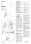
The power supplier is composed of a
power supply module (fig. 1) and a
transformer (fig. 2), which can both be
housed on a DIN rail of 6 modules.
The power supplier provides the power
needed for the central unit and the single
appliances that make up the BRAHMS
B2, burglar alarm system, by means of a
2-wire system bus (non-polarized) with
free topology.
It also provides the energy required to keep
the batteries charged and is capable of
providing maximum current of 300 mA at
12 V to provide power to devices and accessories that are external to the system.
It is equipped with 4 relay outputs with
exchange contacts free of voltage with a
maximum capacity of 1A at 24 V.
The main functions of the power supply
model are:
- Check the status of the main power
supplier, of the batteries and the status of any anti-opening and anti-removal devices if optional container
with tamper is used to house them.
• Package: 1 instruction, 1 transformer
and 1 power supplier.
FUNCTION OF EACH TERMINAL (fig. 2)
Terminal block M1
BUS
BUS output
+
12V
–
power supply 12V 300mA
for accessories
connection
to the battery
input of a tamper
TAMPER
normally closed
+
BAT
–
Terminal block M2
earth
24V
secondary 24 V
30V
secondary 30 V
Terminal block M3
(relay contacts)
NO1 normally open contact 1
C1 common 1
NC1 contact normally closed1
NO2 normally open contact 2
C2 common 2
NC2 contact normally closed2
NO3 normally open contact 3
C3 common 3
NC3 contact normally closed3
NO4 normally open contact 4
C4 common 4
NC4 contact normally closed4
FUNCTION OF JUMPER SW
(bypass of tamper) (fig.2)
The power supply model is equipped
with an SW jumper to disable the tamper
input.
FUNCTION OF THE LED'S (fig. 2)
The power supplier is equipped with four
LED's, with the following functions:
- PWIN (green): presence of mains voltage;
- PWOUT (green): presence of power
supply for the accessories;
- BUSPW (green): presence of voltage
on bus;
- STATUS (red): status of LED.
- slow flashing: normal operation;
- flashing + sounding of buzzer: identification in progress;
- rapid flashing: anomaly, alarm or tampering in progress;
FUNCTION OF FUSES F1 AND F2
Using a screwdriver, you can open the
cover of the power supplier B2AL0001
and access the two fuses identified as
F1 and F2.
F1 of 315 mAT, this is the fuse that protects the auxiliary power supply.
F2 of 1 AT, this is the fuse that protects
the battery.
CONNECTIONS
- Figure 3: example of connection of the
power supply module, of the transformer and of the two batteries (BB065);
- Figure 4: example of connection of telephone dialler GSM04 to the power supply module;
- Figure 5: example of connection of the
power supply module and of the generic loads (U1,U2, U3, U4).
For the 4 outputs located on the power
supplier, there is a standard setting that
automatically matches to each output an
event that can be freely modified in the
programming phase:
OUT 1: Area intrusion alarm from 1÷10;
OUT 2: Sabotage alarm;
OUT 3: Fault;
OUT 4: System disarmed;
The operation of the module will be programmable using the central unit
B2UC0001 (see chapter “Programming
inputs” of the “Technical Manual”).
ATTENTION
• The unit is powered at mains voltage,
230 V AC - 50/60 Hz. Therefore, it
must be provided with an earth connection using the appropriate terminals. Failure to connect all accessible
metal parts to the earth will make the
unit unsafe to use.
• For the 230 V AC power supply, it is
essential to use a cable with double
insulation (with double sheath), as set
forth in electrical safety standards
• Use wire terminals for connection to
the mains at 230V AC - 50/60 Hz.
• Protect the appliance using a suitable
disconnection device to protect the
power supply network such as an easily accessible bi-polar switch (or other).
• Use a cable passage hole only for the
passage of the cable for connection
to the 230V AC - 50/60 Hz mains
• The backup battery should only be replaced by qualified personnel. Dispose of the unit in accordance with
current standards. Use only sealed
lead batteries.
DISPOSAL
Do not litter the environment with packaging material: make sure it is disposed
of according to the regulations in force in
the country where the product is used.
When the equipment reaches the end of
its life cycle, avoid discarding in the environment.
The equipment must be disposed of in
compliance with current regulations, recycling its component parts wherever
possible.
Components that qualify as recyclable
waste feature the relevant symbol and
material acronym.
3