1
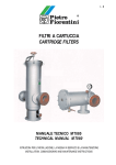
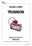
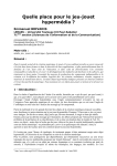
I-E
SCAMBIATORE DI CALORE
HEAT EXCHANGER
KSI
MANUALE TECNICO MT064
TECHNICAL MANUAL MT064
ISTRUZIONI PER L’INSTALLAZIONE, LA MESSA IN SERVIZIO E LA MANUTENZIONE
INSTALLATION, COMMISSIONING AND MAINTENANCE INSTRUCTIONS
MANUALE TECNICO MT064
TECHNICAL MANUAL MT064
KSI
Sfiato aria
Bleed cock
H2O
CH4
Edizione Febbraio 2001
Issue February 2001
2
MANUALE TECNICO MT064
TECHNICAL MANUAL MT064
AVVERTENZE
PRECAUTIONS
AVVERTENZE GENERALI
GENERAL PRECAUTIONS
- L’apparecchiatura descritta in questo manuale è un
dispositivo soggetto a pressione inserito in sistemi
pressurizzati;
- l’apparecchiatura in questione è normalmente inserita in sistemi che trasportano gas infiammabili (ad
esempio gas naturale).
- The apparatus described in this manual is a device
subject to pressure installed in systems under pressure;
- the apparatus in question is normally installed in
systems for transporting flammable gases (natural
gas, for example).
AVVERTENZE PER GLI OPERATORI
PRECAUTIONS FOR THE OPERATORS
Prima di procedere all’installazione, messa in servizio o
manutenzione gli operatori devono:
- prendere visione delle disposizioni di sicurezza
applicabili all’installazione in cui devono operare;
- ottenere le necessarie autorizzazioni ad operare
quando richieste;
- dotarsi delle necessarie protezioni individuali
(casco, occhiali, ecc.);
- assicurarsi che l’area in cui si deve operare sia dotata delle protezioni collettive previste e delle necessarie indicazioni di sicurezza.
Before proceeding with installation, commissioning or
maintenance, operators must:
- examine the safety provisions applicable to the
installation in which they must work;
- obtain the authorisations necessary for working
when so required;
- use the necessary means of individual protection
(helmet, goggles, etc.);
- ensure that the area in which they operate is fitted
with the means of collective protection envisaged
and with the necessary safety indications.
MOVIMENTAZIONE
La movimentazione dell’apparecchiatura e dei suoi
componenti deve essere eseguita dopo aver valutato
che i mezzi di sollevamento siano adeguati ai carichi da
sollevare (capacità di sollevamento e funzionalità). La
movimentazione dell’apparecchiatura deve essere eseguita utilizzando i punti di sollevamento previsti sull’apparecchiatura stessa.
L’impiego di mezzi motorizzati è riservato al personale
a ciò preposto.
HANDLING
INSTALLAZIONE
INSTALLATION
Qualora l’installazione dell’apparecchiatura richieda
l’applicazione in campo di raccordi a compressione,
questi devono essere installati seguendo le istruzioni
del produttore dei raccordi stessi. La scelta del raccordo deve essere compatibile con l’impiego specificato
per l’apparecchiatura e con le specifiche di impianto
quando previste.
If the installation of the apparatus requires the application
of compression fittings in the field, these must be installed following the instructions of the manufacturer of
the fittings themselves. The choice of the fitting must be
compatible with the use specified for the apparatus and
with the specifications of the system when envisaged.
MESSA IN SERVIZIO
COMMISSIONING
La messa in servizio deve essere eseguita da personale
adeguatamente preparato.
Durante le attività di messa in servizio il personale non
strettamente necessario deve essere allontanato e deve
essere adeguatamente segnalata l’area di interdizione
(cartelli, transenne, ecc.).
Verificare che le tarature dell’apparecchiatura siano
quelle richieste; eventualmente provvedere al loro ripristino ai valori richiesti secondo le modalità indicate
oltre nel manuale.
Durante la messa in servizio devono essere valutati i
rischi determinati da eventuali scarichi in atmosfera di
gas infiammabili o nocivi.
Per installazione su reti di distribuzione per gas naturale occorre considerare il rischio di formazioni di miscela esplosiva (gas/aria) all’interno delle tubazioni.
Commissioning must be carried out by adequately trained
personnel.
During the commissioning activities, the personnel not
strictly necessary must be ordered away and the no-go
area must be properly signalled (signs, barriers, etc.).
Check that the settings of the apparatus are those
requested; if necessary, reset them to the required
values in accordance with the procedures indicated in
the manual.
When commissioning, the risks associated with any
discharges into the atmosphere of flammable or
noxious gases must be assessed.
In installations in natural gas distribution networks, the
risk of the formation of explosive mixtures (gas/air)
inside the piping must be considered.
The handling of the apparatus and of its components
must only be carried out after ensuring that the lifting
gear is adequate for the loads to lift (lifting capacity
and functionality). The apparatus must be handled
using the lifting points provided on the apparatus itself.
Motorised means must only be used by the persons in
charge of them.
3
MANUALE TECNICO MT064
TECHNICAL MANUAL MT064
INDICE
INDEX
1.0
INTRODUZIONE
1.1
1.2
PRINCIPALI CARATTERISTICHE
FUNZIONAMENTO
2.0
PAGINA 5
1.
INTRODUCTION
5
5
1.1
1.2
MAIN FEATURES
OPERATION
5
5
INSTALLAZIONE
7
2.0
INSTALLATION
7
2.1
GENERALITA’
7
2.1
GENERAL
7
3.0
MESSA IN SERVIZIO
8
3.0
COMMISSIONING
8
3.1
3.2
GENERALITA’
CONTROLLO TENUTA
8
8
3.1
3.2
GENERAL
TIGHTNESS CONTROL
8
8
4.0
MANUTENZIONE
9
4.0
MODULARITY
14
4.1
4.2
GENERALITA’
9
9
4.1
4.2
MAINTENANCE
9
9
5.0
PESO DEI COMPONENTI
13
5.0
WEIGHT OF THE COMPONENTS
13
5.1
PESO DEI COMPONENTI IN KG
13
5.1
WEIGHT OF THE COMPONENTS IN KG
13
6.0
LISTA DEI RICAMBI
14
6.0
LIST OF RECOMMENDED SPARES
14
4
PAGE 5
MANUALE TECNICO MT064
1.0
TECHNICAL MANUAL MT064
INTRODUZIONE
1.0
INTRODUCTION
Scopo di questo manuale è di fornire informazioni
essenziali per l’installazione, la messa in servizio e la
manutenzione degli scambiatori di calore KSI/...
Si ritiene inoltre opportuno fornire in questa sede una
breve illustrazione delle caratteristiche principali degli
scambiatori e dei suoi accessori.
The scope of this manual is to provide essential information for the installation, commissioning and maintenance of heat exchangers KSI/..
We also consider it appropriate to provide a brief illustration of the main characteristics of the heat exchangers and its accessories.
1.1
1.1
PRINCIPALI CARATTERISTICHE
MAIN FEATURES
• Adatti al preriscaldo di gas naturle, aria, propano e
altri gas non agressivi.
• Tipo BEU: con fascio tubiero ad U completamente
ispezionabile.
Le caratteristiche principali sono:
• Fluido riscaldante: acqua calda e surriscaldata, vapore d’acqua.
• Pressione di progetto: varia come da prescrizione
impianto.
• Temperatura di progetto: varia come da prescrizione
impianto.
• Treccia in rame per continuità elettrica e messa a
terra.
• For pre-heating of natural gas, town gas, air, propane and other not aggressive gases.
• BEU type according to TEMA Code, with bundle fully
removable.
The main features are:
• Heating fluid: hot and super heated water, steam
• Design pressure: varies with the system specification.
• Design temperature: varies with the system specification.
• Copper plate for graunding.
1.2
1.2
FUNZIONAMENTO (FIG. 1)
Il gas freddo entra nel distributore A e passa all’interno
dei tubi del fascio tubiero.
Durante il passaggio per effetto dello scambio tecnico il
gas acquista calore e dopo aver transitato dal distributori B, prosegue quindi verso il bocchello di uscita.
OPERATION (FIG. 1)
The cold gas enters the distributor A and the passes
inside the pipes of the pipe bundle. As an effect of the
heat exchange the gas acquires heat as it passes, and
after transiting distributor B continues towards the
outlet.
5
MANUALE TECNICO MT064
TECHNICAL MANUAL MT064
Tronchetto per valvola di sicurezza
Sfiato aria
Pipe for safety valve
Bleed cook
Entrata acqua
Water inlet
Circuito per preriscaldo pilota
Gas preheating pilot circuits
Uscita acqua
Water outlet
Entrata gas
Uscita gas
Gas inlet
Gas outlet
Drenaggio
Drainage
Fig. 1
6
MANUALE TECNICO MT064
TECHNICAL MANUAL MT064
2.0
INSTALLAZIONE
2.0
INSTALLATION
2.1
GENERALITA’
2.1
GENERAL
Prima di installare lo scambiatore è necessario assicurarsi che:
- lo scambiatore sia inseribile nello spazio previsto e
sia sufficientemente agibile per le successive operazioni di manutenzione;
- le tubazioni di monte e di valle siano al medesimo
livello e in grado di sopportare il peso dello scambiatore;
- le flange di entrata/uscita dello scambiatore siano
parallele;
- le flange di entrata/uscita dello scambiatore siano
pulite e lo scambiatore stesso non abbia subito danni
durante il trasporto;
- la tubazione di monte sia stata pulita al fine di espellere impurità residue quali scorie di saldatura, sabbia, residui di vernice, acqua, ecc.
Before installing the heat exanger, it is necessary to
make sure that:
- the heat exanger can be fitted in the space envisaged
and that it is sufficiently accessible for subsequent
maintenance operations;
- the piping upstream and downstream is at the same
level and capable of supporting the weight of the
heat exanger;
- the inlet/outlet flanges on the piping are parallel;
- the inlet/outlet flanges of the heat exanger are clean
and the heat exanger itself has not been damaged
during transport;
- the piping upstream has been cleaned so as to expel
residual impurities such as welding dross, sand,
paint residues, water, etc.
Lo scambiatore va installato sulla linea orientando la
freccia sul fasciame nel senso del flusso del gas.
The fheat exanger must be installed on the line by
orienting the arrow on the shell in the flow direction of
the gas.
7
MANUALE TECNICO MT064
TECHNICAL MANUAL MT064
3.0
MESSA IN SERVIZIO
3.0
COMMISSIONING
3.1
GENERALITA’
3.1
GENERAL
Si raccomanda di verificare, prima della messa in servizio, che le condizioni di impiego siano conformi alle
caratteristiche delle apparecchiature. Tali caratteristiche sono richiamate con dei simboli sulle targhette di
cui ogni apparecchiatura è munita (Fig. 2).
Before commissioning, we recommend checking
that the conditions of use comply with the characteristics of the apparatus. These characteristics are
recalled by symbols on the plates applied to every
apparatus (Fig. 2).
Fig. 2
3.2
3.2
CONTROLLO TENUTA
TIGHTNESS CONTROL
External tightness is guaranteed when no bubbles
appear when a foaming substance is spread on the element under pressure.
La tenuta esterna è garantita, quando, cospargendo l’elemento in pressione con un mezzo schiumogeno, non
si formano rigonfiamenti di bolle.
8
MANUALE TECNICO MT064
TECHNICAL MANUAL MT064
4.0
MANUTENZIONE
4.0
MAINTENANCE
4.1
GENERALITA’
4.1
GENERAL
Prima di effettuare qualsiasi intervento è importante
accertarsi che lo scambiatore sia stato intercettato a
monte e a valle e che sia stata scaricata la pressione nei
tratti di condotta tra le valvole di intercettazione.
Before carrying out any operation it is important to
ascertain that the heat exanger has been cut off
upstream and downstream and that the pressure has
been discharged in the sections of piping between the
on/off valves.
Gli interventi di manutenzione sono strettamente legati
alla qualità del gas trasportato (impurità, umidità, gasolina, sostanze corrosive).
The maintenance operations depend considerably on
the quanlity of gas piped (impurities, humidity, gasoline, and corrosive substances).
E’ pertanto sempre consigliabile una manutenzione preventiva la cui peridiocità, se non stabilita da normative,
è in relazione:
- alla qualità del gas trasportato.
Preventive maintenance is therefore recommended and
should be carried out with a frequency which, if not laid
down in law, depends on:
- the quality of the gas piped.
Prima di iniziare le operazioni di smontaggio delle
apparecchiature è opportuno accertarsi di:
- disporre di una serie di ricambi consigliati. I ricambi
dovranno essere originali Fiorentini.
Before starting to disassemble the equipment, check
that:
- you have a kit of recommended spares. The spares
must be Fiorentini originals.
N.B. L’impiego di pezzi di ricambio non originali ci
solleva da ogni responsabilità.
N.B. The use of non-original spare parts relieves us
of all responsibility.
- Disporre di una serie di chiavi di cui alla tabella 1.
- Use the set of wrenches specified in table 1.
4.2
CONTROLLO
4.2
Per il controllo del fascio tubiero si procede nel seguente modo (Fig. 3 e 4):
• chiudere le valvole di intercettazione poste a monte e
a valle della linea gas;
• depressurizzare attraverso una valvola di scarico
all’atmosfera il tratto linea gas;
• chiudere la valvola di intercettazione posta sul circuito di riscaldamento;
• svuotare, attraverso l’attacco previsto posto sul mantello dello scambiatore, il liquido riscaldante;
• svitare e togliere le viti che collegano le valvole di
intercettazione del circuito riscaldante allo scambiatore;
• togliere la treccia in rame della continuità elettrica;
• svitare e togliere i dadi di fissaggio pos. 10 del mantello pos. 14 al distributore pos. 1;
• con opportuni mezzi di sollevamento portare in zona
di lavoro l’insieme mantello pos. 14 fascio tubero
pos. 16;
• in zona di lavoro allontanare la vite pos. 40 e togliere
il fascio tubero pos. 16 dal mantello pos. 14.
CONTROL
Proced as follows to control the tube bundle (Fig. 3
and 4):
• close the on/off valves located upstream and downstream in the gas line;
• depressurise the gas line section through a discharge valve to the atmosphere;
• close the on/off valve located in the heating circuit;
• drain the heating liquid through the fitting on the
exchanger skirt;
• unscrew and remove the screws wich connect the
on/off valves of the exchanger heating circuit;
• remove the copper braid for electrical continuity;
• unscrews and remove the nuts, pos. 10, fixing the
skirt, pos. 14, to the distributor, pos. 1;
• take the skirt pos. 14/pipe bundle pos. 16 assembly
to the work area using appropriate lifting gear;
• take out the screw, pos. 40, in the work area and
rmove the pipe bundle, pos. 16, from the skirt, pos.
14.
9
MANUALE TECNICO MT064
TECHNICAL MANUAL MT064
Tronchetto per valvola di sicurezza
Sfiato aria
Pipe for safety valve
Bleed cook
Entrata acqua
Water inlet
Circuito per preriscaldo pilota
Gas preheating pilot circuits
Uscita acqua
Water outlet
Entrata gas
Uscita gas
Gas inlet
Gas outlet
Drenaggio
Drainage
Fig. 3
10
MANUALE TECNICO MT064
TECHNICAL MANUAL MT064
Mantello
Shell
Fascio tubiero
Tube bundle
Distributore
Distributor
Supporto a gonna
Skirt support
Fig. 4
11
MANUALE TECNICO MT064
Tab. 1
TECHNICAL MANUAL MT064
CHIAVI PER LA MANUTENZIONE
Tab. 1
A
KSI/...
Chiave combinata
Combination spanner
MAINTENANCE WRENCHES
B
Chiave regolabile a rullino
Adjustable spanner
I
Giravite lama piatta
Flat head screwdriver
Tipo/Type
KSI/1
KSI/2
KSI/3
KSI/4
KSI/5
KSI/6
KSI/7
A
17-41
17-46
17-41
17-19-46
17-19-46
19-60
19-24-60
B
300
I
65 x 100
12
MANUALE TECNICO MT064
TECHNICAL MANUAL MT064
5.0
PESO DEI COMPONENTI
5.0
WEIGHT OF THE COMPONENTS
5.1
TAB. 2 PESO DEI COMPONENTI IN KG.
5.1
TAB. 2 WEIGHT OF THE COMPONENTS IN KG.
KSI/1
KSI/2
KSI/3
KSI/4
KSI/5
KSI/6
KSI/7
Mantello/Shell
50
80
85
140
270
400
580
Fascio tubiero/Tube bundle
25
50
95
140
250
450
720
Distributore/Distributor
80
130
185
275
350
800
1200
Fascio tubiero
Tube bundle
Mantello
Shell
Distributore
Distributor
Supporto a gonna
Skirt support
13
MANUALE TECNICO MT064
6.0
TECHNICAL MANUAL MT064
LISTA DEI RICAMBI CONSIGLIATI
6.0
14
LIST OF RECOMMENDED SPARES
MANUALE TECNICO MT064
TECHNICAL MANUAL MT064
SCAMBIATORI DI CALORE KSI/...
KSI/... HEAT EXCHANGERS
N. PEZZI/N. OF PIECES
POS.
8
8
62
48
49
DESCRIZIONE
DESCRIPTION
Anello di tenuta O.Ring
Sealing O-Ring
Guarnizione
Gasket
Anello di tenuta O.Ring
Sealing O-Ring
Guarnizione
Gasket
Guarnizione
Gasket
KSI
1-2-6-7
KSI
3-4-5
-
2
2
-
1
1
1
1
1
1
15
MANUALE TECNICO MT064
TECHNICAL MANUAL MT064
PER L’ORDINAZIONE DEI RICAMBI PRECISARE:
WHEN ORDERING SPARE PARTS, PLEASE SPECIFY:
Tipo di scambiatore
N. di Fabbrica (Matricola)
Anno di costruzione
Tipo di fluido impiegato
Il n. del particolare (posizione)
Quantità desiderata
Type of heat exchanger
Works no. (Serial no.)
Year of manufacture
Type of fluid used
The no. of the part (position no.)
Quantity desired
16
MANUALE TECNICO MT064
TECHNICAL MANUAL MT064
NOTE
NOTES
17
MANUALE TECNICO MT064
TECHNICAL MANUAL MT064
NOTE
NOTES
18
MANUALE TECNICO MT064
TECHNICAL MANUAL MT064
I dati sono indicativi e non impegnativi. Ci riserviamo di apportare eventuali modifiche senza preavviso.
The data are not binding. We reserve the right to make modifications without prior notice.
Pietro Fiorentini S.p.A.
UFFICI COMMERCIALI:
OFFICES:
I-20124 MILANO
Italy - Via Rosellini, 1 - Phone +39.02.6961421 (10 linee a.r.) - Telefax +39.02.6880457
E-mail: [email protected]
I-36057 ARCUGNANO (VI) Italy - Via E. Fermi, 8/10 - Phone +39.0444.968511 (10 linee a.r.) - Telefax +39.0444.960468
E-mail: [email protected]
I-80142 NAPOLI
Italy - Via B. Brin, 69 - Phone +39.081.5544308 - +39.081.5537201 - Telefax +39.081.5544568
E-mail: [email protected]
ASSISTENZA POST-VENDITA E SERVIZIO RICAMBI:
SPARE PARTS AND AFTER-SALES SERVICE:
I-36057 ARCUGNANO (VI) - Italy - Via E. Fermi, 8/10 - Phone +39.0444.968511 (10 linee a.r.) - Telefax +39.0444.968513 - E-mail: [email protected]
Edigraf - srl - edizione 02/01