1
ECOFIRE DA INSERIMENTO CANALIZZATA E FRONTALE ISTRUZIONI USO E MANUTENZIONE INSTRUCTIONS FOR USE AND MAINTENANCE GEBRAUCHS- UND WARTUNGSANLEITUNG La stufa a combustione ecologica che riscalda la tua casa The eco-friendly combustion stove that heats your home Der Heizofen mit der umweltfreundlichen Verbrennung, der Ihr ganzes Haus heizt Le apparecchiature da riscaldamento (denominate in seguito “stufe”) PALAZZETTI LELIO S.p.A. (di seguito PALAZZETTI) serie ECOFIRE sono costruite e collaudate seguendo le prescrizioni di sicurezza indicate nelle direttive europee di riferimento. Questo manuale è indirizzato ai proprietari della stufa, agli installatori, operatori e manutentori delle stufe serie ECOFIRE. In caso di dubbi sul contenuto e per ogni chiarimento contattare il costruttore o il servizio di assistenza tecnica autorizzato citando il numero del paragrafo dell'argomento in discussione. La stampa, la traduzione e la riproduzione anche parziale del presente manuale s'intendono vincolata dall'autorizzazione Palazzetti. Le informazioni tecniche, le rappresentazioni grafiche e le specifiche presenti in questo manuale non sono divulgabili. IL SISTEMA A DOPPIA COMBUSTIONE La fiamma prodotta dalla legna che brucia correttamente in una stufa emette la stessa quantità di anidride carbonica (CO2) che si sarebbe liberata in seguito alla naturale decomposizione del legno stesso. La quantità di CO2 prodotta dalla combustione o decomposizione di una pianta corrisponde alla quantità di CO2 che la pianta stessa è in grado di prelevare dall’ambiente e trasformare in ossigeno per l’aria e carbonio per la pianta, nel corso del suo ciclo di vita. L’uso di combustibili fossili non rinnovabili (carbone, gasolio, gas), a differenza di quanto avviene con la legna, libera nell’aria enormi quantità di CO2 accumulate nel corso di milioni di anni, aumentando la formazione dell’effetto serra. L’uso della legna come combustibile, quindi, è in perfetto equilibrio con l’ambiente in quanto viene utilizzato un combustibile rinnovabile ed in armonia con il ciclo ecologico della natura. Il principio della combustione pulita risponde in pieno a questi obiettivi e la Palazzetti vi ha fatto riferimento nella progettazione dei propri prodotti. Cosa intendiamo per combustione pulita e come avviene? Il controllo e la regolazione di aria primaria e l’immissione dell’aria secondaria provoca una seconda combustione, o postcombustione caratterizzata da una seconda fiamma più viva e più limpida che si sviluppa al di sopra della fiamma principale. Essa, grazie all’immissione di nuovo ossigeno, brucia i gas incombusti migliorando sensibilmente il rendimento termico e riducendo al minimo le emissioni nocive di CO (monossido di carbonio) dovute alla combustione incompleta. È questa una caratteristica esclusiva delle stufe e di altri prodotti PALAZZETTI. 2/94 cod. 004770241 - 02/2010 ECOFIRE DA INSERIMENTO IT GB Palazzetti's ECOFIRE series of heating appliances are made and tested following the safety rules and regulations as laid down in the relative European directives. This manual is for owners, installers, operators and maintenance engineers of the ECOFIRE series of stoves. If you have any doubts about the contents or need some clarifications, do not hesitate to contact the manufacturer or an authorised technical assistance centre, giving the number of the paragraph in question. The printing, translation and reproduction, even partial, of this manual are bound by Palazzetti's authorisation. The technical information, graphs and specifications in this manual are not to be disclosed. Die Heizgeräte (anstehend „Heizofen“ genannt) der PALAZZETTI LELIO S.P.A. (in Folge PALAZZETTI) Serie ECOFIRE werden unter Einhaltung der von den diesbezüglichen europäische Richtlinien vorgegebenen Sicherheitsbestimmungen hergestellt und geprüft. Dieses Handbuch richtet sich an den Eigentümer des Heizofens Mod. ECOFIRE, sowie an die Installateure, Bediener und das Wartungspersonal. Im Zweifelsfalle bzw. für jede weitere Erklärung zum Handbuch ist mit dem Hersteller oder der befugten Kundendienststelle Kontakt aufzunehmen. Dabei bitte die Absatznummer und das betroffene Thema angeben. Der Druck, die Übersetzung und auch nur die teilweise Vervielfältigung dieses Handbuchs unterstehen der Genehmigung seitens der Fa. Palazzetti. Die in diesem Handbuch enthaltenen technischen Informationen, grafischen Darstellungen und Spezifikationen dürfen nicht verbreitet werden. DAS SYSTEM DER DOPPELTEN VERBRENNUNG DUAL COMBUSTION SYSTEM In a wood burning stove, a correctly burning flame emits the same amount of carbon dioxide (CO2) as would be emitted through the natural decomposition of the same wood. The quantity of CO2 produced by combustion or decomposition of a tree corresponds to the quantity of CO2 that the tree itself is capable of extracting from the environment and transforming into oxygen for the air and carbon for itself during its lifetime. Unlike wood, when fossil fuels are burned - which are not renewable, like coal, diesel oil, gas - a huge amount of C02 accumulated in the course of millions of years is emitted into the atmosphere, increasing the green-house effect. Consequently, the use of wood as fuel maintains the perfect equilibrium of nature because it is a renewable fuel whose burning is compatible with nature's life cycle. The principle of clean combustion is in perfect harmony with these characteristics and Palazzetti always refers to it when designing its products. What exactly do we mean by clean combustion and how does it come about? By controlling the flow of primary air and by adding secondary air, a second level of combustion, or post-combustion, takes place. This is indicated by a second characteristically clearer and stronger flame above the main flame. By adding new oxygen, this flame consumes the unburned gasses, greatly improving heat production and reducing the harmful emission of CO (carbon monoxide) caused by incomplete combustion. This is a unique feature of the stoves and other PALAZZETTI products. ECOFIRE DA INSERIMENTO Eine in einem Heizofen korrekt brennende Flamme gibt die gleiche Menge an Kohlendioxyd (CO 2) ab, die durch die natürliche Zersetzung des Holzes selbst hätte erzeugt werden können. Die von der Verbrennung oder Zersetzung einer Pflanze erzeugte CO2-Menge entspricht der Menge, die eben diese Pflanze während ihres Lebenszyklus aus der Atmosphäre entnimmt und für die Luft in Sauerstoff bzw. für die Pflanze in Kohlenstoff umwandeln kann. Bei der Verwendung von nicht erneuerbaren Fossilbrennstoffen (Kohle, Dieselöl, Gas) werden im Gegenteil zum Holz enorme Mengen an CO2, das sich im Laufe von Millionen Jahren angesammelt hat, an die Atmosphäre abgegeben, was zur Erhöhung des “Treibhauseffekts” beiträgt. Demnach kann die Anwendung von Holz als Brennstoff als umweltfreundlich angesehen werden, da ein erneuerbarer Brennstoff verwendet wird, der sich harmonisch in den natürlichen, ökologischen Zyklus einfügt. Das von Palazzetti für Heizöfen und Kamine angewandte Prinzip der sauberen Verbrennung entspricht voll und ganz diesen Zielsetzungen, wonach man sich auch in der Planung der Produkte hält. Was versteht man unter sauberer Verbrennung und wie funktioniert sie? Die Kontrolle der Primärluft und die Zufuhr von Sekundärluft bewirken eine zweite Verbrennung bzw. eine so genannte Nachverbrennung, bei der sich eine zweite Flamme über der ersten entwickelt und lebendiger und auch klarer brennt. Sie verbrennt durch die Zufuhr der Sekundärluft die unverbrannten Gase, wodurch die Heizleistung wesentlich verbessert wird: die schädlichen, durch die unvollständige Verbrennung bedingten CO-Emissionen (Kohlenmonoxyd) werden auf ein Minimum reduziert. Es handelt sich hierbei um ein exklusives Merkmal der Öfen und anderen Produkte der Fa. PALAZZETTI. cod. 004770241 - 02/2010 3/94 D IT INDICE 6.2.2.1 Soluzione Standard (ambienti da 40÷60 m2) 6.2.2.2 Soluzione per distribuzione aria calda in più ambienti (fino a 120 m2) 6.3 APPLICAZIONE E COLLEGAMENTI ELETTROVENTILATORE 6.3.1 Preparazione dei tubi 6.3.2 Ventilatore aria 6.3.3 Collegamento del ventilatore 6.3.3 Collegamento del ventilatore 6.3.4 Inserimento sonda ambiente 6.4 COLLEGAMENTO MANDATA ARIA CALDA 6.4.1 Raccordo in controcappa per riscaldamento in unico ambiente 6.4.2 Raccordo a condutture canalizzate per riscaldamento in più ambienti 1 PREMESSA 1.1 SIMBOLOGIA 1.2 DESTINAZIONE D’USO 1.3 SCOPO E CONTENUTO DEL MANUALE 1.4 CONSERVAZIONE DEL MANUALE 1.5 AGGIORNAMENTO DEL MANUALE 1.6 INFORMAZIONI GENERALI 1.7 PRINCIPALI NORME ANTIFORTUNISTICHE RISPETTATE E DA RISPETTARE 1.8 GARANZIA LEGALE 1.9 RESPONSABILITÀ DEL COSTRUTTORE 1.10 CARATTERISTICHE DELL’UTILIZZATORE 1.11 ASSISTENZA TECNICA 6.5 SCHEMA DI MONTAGGIO 1.12 PARTI DI RICAMBIO 6.6 1.13 TARGHETTA DI IDENTIFICAZIONE REALIZZAZIONE FORI TECNICI SUL RIVESTIMENTO 1.14 CONSEGNA DELLA STUFA 6.7 ALLACCIAMENTO AGLI IMPIANTI 6.7.1 Collegamento elettrico 2 AVVERTENZE PER LA SICUREZZA 6.7.1.1 Messa a terra 2.1 AVVERTENZE PER L’INSTALLATORE 6.7.2 Installazione del pannello di controllo 2.2 AVVERTENZE PER L’UTILIZZATORE 6.7.3 Collegamento al termostato ambiente 2.3 AVVERTENZE PER IL MANUTENTORE 6.7.4 Collegamento al GSM FIRE CONTROL (GFC) 3 CARATTERISTICHE DEL COMBUSTIBILE E DESCRIZIONE DELLA STUFA 7 MESSA IN SERVIZIO ED USO DELLA STUFA 3.1 CARATTERISTICHE DEL COMBUSTIBILE 7.1 CARICAMENTO COMBUSTIBILE 3.2 STOCCAGGIO DEL PELLET 7.1.1 Pellet 3.3 DESCRIZIONE DELLE PARTI PRINCIPALI DELLA STUFA 7.2 DESCRIZIONE PANNELLO COMANDI 7.2.1 Blocco tastiera 7.3 FASE DI AVVIO DELLA COMBUSTIONE 7.3.1 Operazioni preliminari 7.3.2 Accensione stufa 4 MOVIMENTAZIONE E TRASPORTO 5 PREPARAZIONE DEL LUOGO DI INSTALLAZIONE 5.1 PRECAUZIONI PER LA SICUREZZA 7.3.2.1 Accensione a pellet (Automatica) 5.2 CONSIDERAZIONI GENERALI 7.4 FASE DI LAVORO 5.3 LUOGO DI INSTALLAZIONE DELLA STUFA 7.4.1.1 Descrizione dei parametri 5.4 SCARICO FUMI 7.4.1.2 Regolazione dei parametri 5.4.1 Scarico a tetto mediante canna fumaria 7.5 FASE DI SPEGNIMENTO DELLA STUFA 7.6 USO AVANZATO DEL PANNELLO COMANDO 6 INSTALLAZIONE 7.6.1 MENU SET LAVORO 6.1 INSTALLAZIONE GENERATORE DA INCASSO (CON BASAMENTO DI ESTRAZIONE) 7.6.2 MENU TIMER 6.1.2 Installazione senza telaio basamento 7.6.3 MENU SET STUFA 6.2 PRESE D’ARIA 7.6.3.1 OROLOGIO 6.2.1 Presa aria comburente 7.6.3.2 LINGUA 6.2.2 Presa aria ventilatore 7.6.3.3 TIPO MENU 7.6.3.4 FUNZ. TOTALE 4/94 cod. 004770241 - 02/2010 ECOFIRE DA INSERIMENTO IT 7.6.3.5 ORE RESIDUE 7.6.3.6 START EXT. 7.6 GESTIONE ERRORI 7.6.1 Premessa 7.6.1.1 ERRORE 501 7.6.1.2 ERRORE 502 7.6.1.3 ERRORE 503 7.6.1.4 ERRORE 504 7.6.1.5 ERRORE 507 7.6.1.6 ERRORE 508 7.6.1.7 ERRORE 510 7.6.1.8 ERRORE 511 7.6.1.9 ERRORE 513 7.6.2 Ripristino stufa dagli ERRORI 7.6.3 Tabella riassuntiva Errori 7.8 GESTIONE AVVISI 7.7.1 Premessa 7.7.2 Descrizione degli avvisi 7.7.3 Tabella riassuntiva Avvisi 7.9 PULIZIA STUFA 8 MANUTENZIONE E PULIZIA 8.1 PRECAUZIONI DI SICUREZZA 8.2 MANUTENZIONE ORDINARIA RIVOLTA ALL’UTILIZZATORE 8.2.1 Apertuta porta 8.2.2 Pulizia interna del focolare 8.2.3 Pulizia del vetro 8.2.4 Pulizia della canna fumaria 8.3 Pulizia coclea 8.4 MANUTENZIONE STRAORDINARIA 9 INFORMAZIONI PER LA DEMOLIZIONE E LO SMALTIMENTO 10 SCHEMA ELETTRICO LEGENDA TARGHETTA MATRICOLA CARATTERISTICHE TECNICHE ECOFIRE DA INSERIMENTO cod. 004770241 - 02/2010 5/94 GB INDEX 6.2.2 Fan air intake 6.2.2.1 Standard solution (for 40-60 m2 rooms) 6.2.2.2 Solution for distributing hot air in more than one room (up to 120 m2) 6.3 ELECTRIC FAN APPLICATION AND CONNECTIONS 6.3.1 Preparing the ducts 6.3.2 Air fan 6.3.3 Connecting the fan 6.3.4 Installation of a room temperature probe 6.4 HOT AIR DELIVERY CONNECTION 1 GENERAL 1.1 SYMBOLS 1.2 USE OF THE STOVE 1.3 PURPOSE AND CONTENTS OF THE MANUAL 1.4 KEEPING THE MANUAL 1.5 UPDATING THE MANUAL 1.6 GENERAL INFORMATION 1.7 MAIN ACCIDENT PREVENTION REGULATIONS TO COMPLY WITH 1.8 LEGAL GUARANTEE 6.4.1 Protection hood connections for heating one room 1.9 THE MANUFACTURER'S LIABILITIES 6.4.2 Duct connections for heating several rooms 1.10 USER CHARACTERISTICS 6.5 ASSEMBLY DIAGRAM 1.11 TECHNICAL ASSISTANCE 6.6 CREATION OF UTILITY HOLES ON CLADDING 1.12 SPARE PARTS 6.7 CONNECTION TO SYSTEMS 1.13 IDENTIFICATION PLATE 6.7.1 Electrical connection 1.14 DELIVERY OF THE STOVE 6.7.1.1 Earthing 6.7.2 Control panel installation 2 SAFETY PRECAUTIONS 6.7.3 Connection to room thermostat 2.1 INSTRUCTIONS FOR THE INSTALLER 6.7.4 Connection to GSM FIRE CONTROL (GFC) 2.2 INSTRUCTIONS FOR THE USER 2.3 INSTRUCTIONS FOR THE MAINTENANCE ENGINEER 7 COMMISSIONING AND USING THE STOVE 7.1 LOADING THE PELLETS 7.2 DESCRIPTION OF THE CONTROL PANEL 7.2.1 Keypad lock 3 FUEL CHARACTERISTICS AND A DESCRIPTION OF THE STOVE 3.1 FUEL CHARACTERISTICS 7.3 COMBUSTION START PHASE 3.2 STORING THE PELLETS 7.3.1 Preliminary operations 3.3 DESCRIPTION OF THE STOVE'S MAIN PARTS 7.3.2 Fireplace lighting 7.3.2.1 Pellet ignition (Automatic) 4 HANDLING AND TRANSPORT 7.4 WORKING PHASE 5 PREPARING THE PLACE OF INSTALLATION 7.4.1 Description of parameters 7.4.2 Setting parameters 5.1 SAFETY PRECAUTIONS 7.5 TURNING THE STOVE OFF PHASE 5.2 GENERAL CONSIDERATIONS 7.6 ADVANCED USE OF THE CONTROL PANEL 5.3 CLEARANCE AROUND THE STOVE 7.6.1 WORK SET menu 5.4 AIR FOR COMBUSTION 7.6.2 Menu TIMER 5.5 FLUE 7.6.3 Menu SET STOVE 5.5.1 Discharge through the roof with a flue 7.6.3.1 CLOCK 6 INSTALLATION 7.6.3.2 LANGUAGE 6.1 INSTALLATION OF RECESSED GENERATOR (WITH EXTRACTION BASE) 7.6.3.3 MENU TYPE 7.6.3.4 TOTAL OPERATION 6.1.2 Installation without base frame 7.6.3.5 HOURS REMAINING 6.2 AIR INTAKE 7.6.3.6 START EXT. 6.2.1 Combustion air intake 7.7 ERROR MANAGMENT 6/94 cod. 004770241 - 02/2010 ECOFIRE DA INSERIMENTO GB 7.7.1 Introduction 7.7.1.1 ERROR 501 7.7.1.2 ERROR 502 7.7.1.3 ERROR 503 7.7.1.4 ERROR 504 7.7.1.5 ERROR 507 7.7.1.6 ERROR 508 7.7.1.7 ERROR 510 7.7.1.8 ERROR 511 7.7.1.9 ERROR 513 7.7.2 Resetting the fireplace after errors 7.7.3 Summary table of errors 7.8 MANAGEMENT OF NOTICES 7.8.1 Introduction 7.8.2 Description of the notices 7.8.3 Summary table of notices 7.9 FIREPLACE CLEANING 8 MAINTENANCE AND CLEANING 8.1 SAFETY PRECAUTIONS 8.2 ROUTINE MAINTENANCE FOR THE USER 8.2.1 Cleaning the hearth interior 8.2.2 Cleaning the ash box 8.2.3 Cleaning the glass 8.2.4 Cleaning the flue 8.2.5 Adjusting the handle 9 INFORMATION FOR DEMOLITION AND DISPOSAL 10 ELECTRICAL DIAGRAM LEGEND PRODUCT LABEL TECHNICAL FEATURES ECOFIRE DA INSERIMENTO cod. 004770241 - 02/2010 7/94 D NHALTSVERZEICHNIS 6.2.2 Öffnung Ventilatorluft 6.2.2.1 Standard Ausführung (für Räume mit 40-60 m2) 6.2.2.2 Ausführung mit Verteilung der Warmluft in Mehreren Räumen (bis zu 120 m2) 1 EINLEITUNG 1.1 SYMBOLE 1.2 ANWENDUNGSZWECK 6.3 ANSCHLUSS DES ELEKTROGEBLÄSES 1.3 ZWECK UND INHALT DES HANDBUCHS 6.3.1 Vorbereitungderrohre 1.4 AUFBEWAHRUNG DES HANDBUCHS 6.3.2 Luftgebläse 1.5 ERGÄNZUNG DES HANDBUCHS 6.3.3 Anschluss des Gebläses 1.6 ALLGEMEINE INFORMATIONEN 6.3.4 Einbau des Raumtemperaturfühlers 1.7 GRUNDLEGENDE EINGEHALTENE UND EINZUHALTENDE UNFALLVERHÜTUNGSNORMEN 6.4 ANSCHLUSS WARMLUFT-VORLAUF 6.4.1 Anschluss an eine Gegenhaube zum Heizen eines Einzingen Räumes 1.8 GEWÄHRLEISTUNG 6.4.2 1.9 HAFTBARKEIT DES HERSTELLERS Anschluss an Leitungen zum Heizen Mehrerer Räume 1.10 EIGENSCHAFTEN DES BENUTZERS 6.5 MONTAGEPLAN 1.11 TECHNISCHER KUNDENDIENST 6.6 1.12 ERSATZTEILE AUSFÜHRUNG DER TECHNISCHEN BOHRUNGEN AN DER VERKLEIDUNG 1.13 TYPENSCHILD 6.7 VERSCHIEDENE ANSCHLÜSSE 1.14 LIEFERUNG DES HEIZOFENS 6.7.1 Stromanschluss 6.7.1.1 Erdung 2 SICHERHEITSHINWEISE 6.7.2 Installaton der Bedienblende 2.1 HINWEISE FÜR DEN INSTALLATEUR 6.7.3 Anschluss an den Raumthermostat 2.2 HINWEISE FÜR DEN BENUTZER 6.7.4 Anschluss des GSM FIRE CONTROL (GFC) 2.3 HINWEISE FÜR DAS WARTUNGSPERSONAL 7 3 BRENNSTOFFEIGENSCHAFTEN UND GERÄTEBESCHREIBUNG INBETRIEBNAHME UND GEBRAUCH DES HEIZOFENS 7.1 EINFÜLLEN DER PELLETS 3.1 BRENNSTOFFEIGENSCHAFTEN 7.2 BESCHREIBUNG DER BEDIENBLENDE 3.2 LAGERUNG DER PELLET 7.2.1 Tastensperre 3.3 BESCHREIBUNG DER HAUPTBESTANDTEILE DES HEIZOFENS 7.3 START DER VERBRENNUNG 7.3.1 Vorbereitungen HANDLING UND TRANSPORT 7.3.2 Zündung des Heizkamins 7.3.2.1 Zündung mit Pellets (automatisch) 7.4 BETRIEBSPHASE 7.4.1 Beschreibung der Parameter 7.4.2 Parametereinstellungen 7.5 AUSSCHALTPHASE DES HEIZOFENS 7.6 ERWEITERTER GEBRAUCH DER BEDIENBLENDE 4 5 VORBEREITUNG DES INSTALLATIONSORTS 5.1 VORBEUGENDE SICHERHEITSMASSNAHMEN 5.2 ALLGEMEINE ANMERKUNGEN 5.3 VORBEREITUNG DES INSTALLATIONSORTS 5.4 VERBRENNUNGSLUFT 5.5 ABGASLEITUNG 7.6.1 Menu BETRIEBSEINSTELLUNGEN 5.5.1 Abzug am Dach mit Rauchfang 7.6.2 Menü TIMER 6 INSTALLATION 7.6.3 Menü EINSTELLUNG 6.1 INSTALLATION DES EINBAUGENERATORS (MIT AUSZUGSSOCKEL) 7.6.3.1 UHR 7.6.3.2 SPRACHE 6.1.2 Installation ohne Sockelgestell 7.6.3.3 MENÜTYP 6.2 LÜFTUNGSKLAPPE 7.6.3.4 TOTALE FUNK. 6.2.1 Öffnung Verbrennungsluft 7.6.3.5 RESTLICHE STUNDEN 8/94 cod. 004770241 - 02/2010 ECOFIRE DA INSERIMENTO D 7.6.3.6 EXT. START 7.7 FEHLERBESEITIGUNG 7.7.1 Vorwort 7.7.1.1 FEHLER 501 7.7.1.2 FEHLER 502 7.7.1.3 FEHLER 503 7.7.1.4 FEHLER 504 7.7.1.4 FEHLER 504 7.7.1.5 FEHLER 507 7.7.1.6 FEHLER 508 7.7.1.7 FEHLER 510 7.7.1.8 FEHLER 511 7.7.1.9 FEHLER 513 7.7.2 Rücksetzung der aufgetretenen Fehler im Heizkamin 7.7.3 Zusammenfassende Fehlertabelle 7.8 STEUERUNG DER HINWEISE 7.8.1 Vorwort 7.8.2 Beschreibung der Hinweise 7.8.3 Zusammenfassende Tabelle der Hinweise 7.9 REINIGUNG DES HEIZKAMINS 8 INSTANDHALTUNG UND REINIGUNG 8.1 VORBEUGENDE SICHERHEITSMASSNAHMEN 8.2 REGELMÄSSIGE INSTANDHALTUNG (FÜR DEN BENUTZER) 8.2.1 Interne Reinigung der Feuerstelle 8.2.1.1 Apertuta porta FRED DY 8.2.2 Reinigung des Aschenkastens 8.2.3 Reinigung des Glases 8.2.4 Reinigung des Rauchfangs 8.2.5 Griffeinstellung 8.3 REINIGUNG SCHNECKE 8.4 AUSSERORDENTLICHE INSTANDHALTUNG 9 INFORMATIONEN FÜR DEN ABRISS UND DIE ENTSORGUNG 10 ELEKTRISCHER SCHALTPLAN BESCHREIBUNG TYPENSCHILD TECHNISCHE EIGENSCHAFTEN ECOFIRE DA INSERIMENTO cod. 004770241 - 02/2010 9/94 Gentile cliente, desideriamo innanzitutto ringraziarLa per la preferenza che ha voluto accordarci acquistando il nostro prodotto e ci congratuliamo con Lei per la scelta. Per consentirLe di utilizzare al meglio la Sua nuova stufa ECOFIRE, la invitiamo a seguire attentamente quanto descritto nel presente manuale. 1 PREMESSA Non operare se non si sono ben comprese tutte le notizie riportate nel manuale; in caso di dubbi richiedere sempre l’intervento di personale specializzato PALAZZETTI. Palazzetti si riserva il diritto di modificare specifiche e caratteristiche tecniche e/o funzionali della stufa in qualsiasi momento senza darne preavviso. 1.1 SIMBOLOGIA Nel presente manuale i punti di rilevante importanza sono evidenziati dalla seguente simbologia: ! ! INDICAZIONE: Indicazioni concernenti il corretto utilizzo della stufa e le responsabilità dei preposti. ! PERICOLO: Viene espressa un’importante nota di comportamento per la prevenzione di infortuni o danni materiali. 1.2 DESTINAZIONE D’USO ! ATTENZIONE: Punto nel quale viene espressa una nota di particolare rilevanza. L’apparecchiatura PALAZZETTI modello ECOFIRE è la nuova stufa per il riscaldamento, tecnologicamente avanzata, funzionante esclusivamente a pellet, che produce calore in un ambiente sano e sicuro, mediante funzionamento automatico. La stufa funziona unicamente con la porta del focolaio chiusa. Non si deve mai aprire la portina durante il funzionamento della stufa. La stufa è caratterizzata da un doppio sistema di combustione PRIMARIA e SECONDARIA con effetti positivi sia sul rendimento che sulla emissione di “fumi più puliti”. La destinazione d’uso sopra riportata e le configurazioni previste della stufa sono le uniche ammesse dal Costruttore: non utilizzare la stufa in disaccordo con le indicazioni fornite. ! 10/94 La destinazione d’uso indicata è valida solo per apparecchiature in piena efficienza strutturale, meccanica ed impiantistica. La stufa PALAZZETTI è un apparecchio solo da interno. cod. 004770241 - 02/2010 ECOFIRE DA INSERIMENTO IT GB 1 Dear customer, Sehr geehrter Kunde, We would first of all like to thank you for having chosen one of our products and congratulate you on your choice. Zuallererst möchten wir Ihnen für den uns gewährten Vorzug danken und Ihnen zur Wahl gratulieren. Inorder for you to get the best out of your new ECOFIRE stove, please follow the advice and instructions given in this manual. Damit Sie Ihren neuen Heizofen ECOFIRE so gut wie möglich benutzen können, bitten wir Sie, die in dieser Bedienungs- und Wartungsanleitung enthaltenen Angaben genau zu befolgen. GENERAL 1 Do not start using the stove until you have read and understood the contents of this manual. If you have any doubts at any time do not hesitate to call the PALAZZETTI specialised personnel who are there to help you. Keinesfalls vorgehen, wenn sie nicht alle Hinweise des Handbuchs verstanden haben; im Zweifelsfall immer den Eingriff von Fachpersonal der Fa. PALAZZETTI anfordern. Die Firma Palazzetti behält sich das Recht vor, Spezifikationen und technische bzw. funktionelle Eigenschaften des Geräts jederzeit und ohne Vorbescheid zu ändern. Palazzetti reserves the right to modify the technical and/ or functional specifications and features at any time without prior notice. 1.1 SYMBOLS The important points in this manual are highlighted with the following symbols: ! ! INDICATION: Indications concerning the correct use of the stove and the responsibilities of those using it. EINLEITUNG 1.1 SYMBOLE In diesem Handbuch sind die wichtigen Punkte durch folgende Symbole gekennzeichnet: HINWEIS: Hinweise zum korrekten Gebrauch des Heizofens unter Verantwortung des Bedieners. ATTENTION: A particularly important note is written here. ! ! ! DANGER: Here you are warned of the possibility of bodily harm or material damage. ! GEFAHR: Hierbei handelt es sich um wichtige Verhaltenshinweise zur Vorbeugung von Verletzungen oder Materialschäden. 1.2 USE OF THE STOVE 1.2 ANWENDUNGSZWECK ! ECOFIRE is the new, technologically advanced PALAZZETTI stove for heating that only burns pellets, providing a healthy and safe way to heat a room automatically. ! The stove will only operate when the door of the combustion chamber is closed. Der ECOFIRE von PALAZZETTI ist ein neuer, technologisch fortgeschrittener Heizofen, der ausschließlich mit Pellets beschickt wird und im Automatikbetrieb Wärme für ein gesundes und sicheres Ambiente erzeugt. The door must never be opened while the stove is operating. Der Heizofen funktioniert ausschließlich bei geschlossener Feuerraumtür. This stove features the dual PRIMARY and SECONDARY combustion system with positive effects both on efficiency and on the emission of "cleaner smoke". Die Tür während des Heizofenbetriebs nie öffnen. Der Heizofen zeichnet sich durch ein doppeltes Verbrennungssystem mit PRIMÄRUND SEKUNDÄRVERBRENNUNG aus, was sich nicht nur auf die Heizleistung positiv auswirkt, sondern auch „reinere Abgase“ bewirkt. Use of the stove, as described above, and its configurations are only those allowed by the manufacturer: do not use the stove in contravention of the indications provided. ! ACHTUNG: Damit werden besonders wichtige Anmerkungen gekennzeichnet. The use of the stove indicated is applicable only for stoves in full structural, mechanical and engineering efficiency. The PALAZZETTI stove is only an indoor stove. ECOFIRE DA INSERIMENTO Der oben genannte Anwendungszweck bzw. die für das Gerät vorgesehenen Konfigurationen sind die einzigen vom Hersteller zugelassenen: das Gerät nicht gegen die gelieferten Anweisungen verwenden. ! Der angegebene Anwendungszweck gilt nur für Geräte mit einwandfreier Struktur, Mechanik und Anlage. Der Heizofen von PALAZZETTI ist nur für Innenräume geplant. cod. 004770241 - 02/2010 11/94 D 1.3 SCOPO E CONTENUTO DEL MANUALE SCOPO Lo scopo del manuale è quello di consentire all’utilizzatore di prendere quei provvedimenti e predisporre tutti i mezzi umani e materiali necessari per un suo uso corretto, sicuro e duraturo. CONTENUTO Questo manuale contiene tutte le informazioni necessarie per l’installazione, l’impiego e la manutenzione della stufa ECOFIRE. La scrupolosa osservanza di quanto in esso descritto garantisce un elevato grado di sicurezza e produttività della stufa. 1.4 CONSERVAZIONE DEL MANUALE CONSERVAZIONE E CONSULTAZIONE Il manuale deve essere conservato con cura e deve essere sempre disponibile per la consultazione, sia da parte dell’utilizzatore che degli addetti al montaggio ed alla manutenzione. Il manuale Istruzione Uso e Manutenzione è parte integrante della stufa. DETERIORAMENTO O SMARRIMENTO In caso di necessità fare richiesta di un’ulteriore copia a PALAZZETTI. CESSIONE DELLA STUFA In caso di cessione della stufa l'utente è obbligato a consegnare al nuovo acquirente anche il presente manuale. 1.5 AGGIORNAMENTO DEL MANUALE Il presente manuale rispecchia lo stato dell'arte al momento dell’immissione sul mercato della stufa. Le stufe già presenti sul mercato, con la relativa documentazione tecnica, non verranno considerate da PALAZZETTI carenti o inadeguate a seguito di eventuali modifiche, adeguamenti o applicazione di nuove tecnologie su stufe di nuova commercializzazione. 1.6 GENERALITÀ INFORMAZIONI In caso di scambio di informazioni con il Costruttore della stufa fare riferimento al numero di serie ed ai dati identificativi indicati alla pagina “INFORMAZIONI GENERALI” alla fine del presente manuale. RESPONSABILITÀ Con la consegna del presente manuale PALAZZETTI declina ogni responsabilità, sia civile che penale, per incidenti derivati dalla non osservanza parziale o totale delle specifiche in esso contenute. ! PALAZZETTI declina, altresì, ogni responsabilità derivante da uso improprio della stufa od uso non corretto da parte dell’utilizzatore, da modifiche e/o riparazioni non autorizzate, da utilizzo di ricambi non originali o non specifici per questo modello di stufa. MANUTENZIONE STRAORDINARIA Le operazioni di manutenzione straordinaria devono essere eseguite da personale qualificato ed abilitato ad intervenire sul modello di stufa a cui fa riferimento il presente manuale. 12/94 cod. 004770241 - 02/2010 ECOFIRE DA INSERIMENTO IT GB 1.3 PURPOSE AND CONTENTS OF THE MANUAL 1.3 ZWECK Zweck des Handbuchs ist es, dem Bediener die nötigen Grundlagen zu liefern, um für einen korrekten, sicheren und dauerhaften Gebrauch des Heizofens die geeigneten Maßnahmen zu treffen bzw. alle menschlichen und materiellen Mittel zur Verfügung zu stellen. PURPOSE The purpose of the manual is to allow the user to take the necessary precautions and to have all the human and material means required for its correct, safe and lasting use. CONTENTS This manual contains all the information necessary for installation, use and maintenance of the ECOFIRE stove. INHALT Dieses Handbuch enthält alle für die Installation, den Gebrauch und die Wartung des Heizofens ECOFIRE nötigen Informationen. By complying scrupulously with the contents of this manual you will ensure a high degree of safety and productivity of the stove. 1.4 KEEPING THE MANUAL KEEPING AND CONSULTING THE MANUAL The manual must be kept in a safe, dry place and be available at all times for consultation by the user and by those who see to its installation and maintenance. Die gewissenhafte Beachtung aller Anweisungen gewährleistet einen hohen Sicherheits- und Produktivitätsgrad des Heizofens. 1.4 DETERIORATION OR LOSS If required, ask Palazzetti for another copy of the manual. Das Handbuch Wartungsanleitung” Gerätebestandteil. SELLING THE STOVE If the stove is sold the user must give the manual to the new owner as well. VERKAUF DES HEIZOFENS Beim eventuellen Verkauf des Heizofens muss dem neuen Käufer auch das Handbuch ausgehändigt werden. This manual reflects the state-of-the-art at the time the appliance was put on the market. 1.6 1.5 Die bereits am Markt befindlichen Geräte und deren technische Dokumentation werden von der Fa. PALAZZETTI nach eventuellen Änderungen, Anpassungen oder Anwendung neuer Technologien für neue Geräte nicht als überholt bzw. ungeeignet angesehen. 1.6 LIABILITIES Upon delivery of this manual PALAZZETTI declines all liabilities, both civil and penal, for any accidents that may derive from the total or partial failure to comply with the specifications contained in it. ! ECOFIRE DA INSERIMENTO ALLGEMEINE INFORMATIONEN INFORMATIONEN Bei Nachfragen beim Heizofenhersteller immer die Seriennummer und die Identifikationsdaten angeben. Diese Daten sind der Seite „ALLGEMEINE INFORMATIONEN“ am Ende dieses Handbuchs zu entnehmen. PALAZZETTI also declines all liabilities resulting from an improper use of the stove, incorrect use by the user or resulting from unauthorised alterations and/or repairs, or the use of spare parts that are either not genuine or not specific for this particular model. EXTRAORDINARY MAINTENANCE Extraordinary maintenance must be carried out by personnel qualified to work on the stove model to which this manual refers. ERWEITERUNG DES HANDBUCHS Dieses Handbuch entspricht dem technischen Stand zum Zeitpunkt der Erstvermarktung des Geräts. GENERAL INFORMATION INFORMATION If there is an exchange of information with the stove manufacturer, please quote the serial number and identification data which you will find on the "GENERAL INFORMATION" page at the end of this manual. “Gebrauchsund ist integrierender VERSCHLEISS ODER VERLUST Bei Notwendigkeit bei der Fa. PALAZZETTI eine Ersatzkopie anfordern MANUAL UPDATE The appliances already on the market, together with their technical documentation, will not be considered as wanting or inadequate simply because changes or adjustments have been made or new technologies have been applied to the next generation of appliances. AUFBEWAHRUNG DES HANDBUCHS AUFBEWAHRUNG UND NACHSCHLAGEN Die Betriebsanleitungen müssen sorgfältig aufbewahrt werden und sollten sowohl dem Benutzer, als auch den mit der Montage und der Wartung beauftragten Fachleuten ständig zur Einsichtnahme zur Verfügung stehen. The instructions for use and maintenance manual is an integral part of the stove. 1.5 ZWECK UND INHALT DES HANDBUCHS HAFTBARKEIT Mit der Übergabe dieses Handbuchs weist die Fa. PALAZZETTI jede sowohl zivil- als auch strafrechtliche Haftbarkeit für Unfälle zurück, die zwecks mangelnder oder kompletter Nichtbeachtung der darin enthaltenen Spezifikationen entstehen. ! Die Firma PALAZZETTI weist des Weiteren jede Verantwortung zurück, die sich aus einem unzweckmäßigen oder nicht korrekten Gerätegebrauch cod. 004770241 - 02/2010 13/94 D ! RESPONSABILITÀ DELLE OPERE DI INSTALLAZIONE La responsabilità delle opere eseguite per l'installazione della stufa non può essere considerata a carico della PALAZZETTI, essa è, e rimane, a carico dell’installatore, al quale è demandata l’esecuzione delle verifiche relative alla canna fumaria e della presa d’aria ed alla correttezza delle soluzioni di installazione proposte. Inoltre devono essere rispettate tutte le norme di sicurezza previste dalla legislazione specifica vigente nello stato dove la stessa è installata. USO L'uso della stufa è subordinato, oltre che alle prescrizioni contenute nel presente manuale, anche al rispetto di tutte le norme di sicurezza previste dalla legislazione specifica vigente nello stato dove la stessa è installata. 1.7 PRINCIPALI NORME ANTIFORTUNISTICHE RISPETTATE E DA RISPETTARE A) Direttiva 2006/95/CE: "Materiale elettrico destinato ad essere adoperato entro taluni limiti di tensione ". B) Direttiva 2004/108/CE: "Ravvicinamento delle legislazioni degli Stati membri relative alla compatibilità elettromagnetica". C) Direttiva 89/391/CEE: "Attuazione delle misure volte a promuovere il miglioramento della sicurezza e della salute dei lavoratori durante il lavoro". D) Direttiva 89/106/CEE: "Concernente il riavvicinamento delle disposizioni legislative, regolamentari ed amministrative degli stati membri concernenti i prodotti da costruzione". E) Direttiva 85/374/CEE: "Concernente il riavvicinamento delle disposizioni legislative, regolamentari ed amministrativee degli stati membri in materia di responsabilità per danno da prodotti difettosi". F) Direttiva 1999/5/CE: “Riguardante le apparecchiature radio e le apparecchiature terminali di telecomunicazione e il reciproco riconoscimento della loro conformità”. 1.8 GARANZIA LEGALE L'utente per poter usufruire della garanzia legale, di cui alla Direttiva CEE 1999/44/CE deve osservare scrupolosamente le prescrizioni indicate nel presente manuale, ed in particolare: - operare sempre nei limiti d'impiego della stufa; - effettuare sempre una costante e diligente manutenzione; - autorizzare all’uso della stufa persone di provata capacità, attitudine ed adeguatamente addestrate allo scopo. L'innosservanza delle prescrizioni contenute in questo manuale implicherà l’immediata decadenza della garanzia. 1.9 ! RESPONSABILITÀ DEL COSTRUTTORE Il Costruttore declina ogni responsabilità civile e penale, diretta o indiretta, dovuta a: - 14/94 cod. 004770241 - 02/2010 installazione non conforme alle normative vigenti nel paese ed alle direttive di sicurezza; ECOFIRE DA INSERIMENTO IT GB ! RESPONSIBILITY FOR INSTALLATION It is not PALAZZETTI's responsibility to carry out the work needed to install the stove. Such work is entirely up to the installer who is required to check the flue and air intake and to check if the installation solutions proposed are feasible. In addition, all the safety standards established by the relevant law in force in the place of installation must be complied with. USE Use of the stove is subject to compliance with all the safety standards established by the relevant laws in force in the place of installation besides the prescriptions contained in this manual. 1.7 A) C) Directive 89/391/EEC: “On the introduction of measures to encourage improvements in the safety and health of workers at work”. F) 1.8 GEBRAUCH Der Gebrauch des Geräts untersteht nicht nur den präzisen Anweisungen dieses Handbuchs, sondern auch der Beachtung aller im Installationsland vorgesehenen Sicherheitsnormen. 1.7 GRUNDLEGENDE EINGEHALTENE UND EINZUHALTENDE UNFALLVERHÜTUNGSNORMEN A) Directive 85/374/EEC: “On the approximation of the laws, regulations and administrative provisions of the Member States concerning liability for defective products”. Richtlinie 2006/95/EWG: “zur Angleichung der Rechtsvorschriften der Mitgliedstaaten betreffend elektrische Betriebsmittel zur Verwendung innerhalb bestimmter Spannungsgrenzen”. B) Directive 1999/5/EC: “On radio equipment and telecommunications terminal equipment and the mutual recognition of their conformity”. Richtlinie 2004/108/EWG: “zur Angleichung der Rechtsvorschriften der Mitgliedstaaten über die elektromagnetische Verträglichkeit”. C) Richtlinie 89/391/EWG: “über die Durchführung von Maßnahmen zur Verbesserung der Sicherheit und des Gesundheitsschutzes der Arbeitnehmer bei der Arbeit”. D) Richtlinie 89/106/EWG: “zur Angleichung der Rechtsund Verwaltungsvorschriften der Mitgliedstaaten über Bauprodukte”. E) Richtlinie 85/374/EWG: “zur Angleichung der Rechtsund Verwaltungsvorschriften der Mitgliedstaaten über die Haftung für fehlerhafte Produkte”. F) Richtlinie 1999/5/EG: “über Funkanlagen und Telekommunikationsendeinrichtungen und die gegenseitige Anerkennung ihrer Konformität”. LEGAL GUARANTEE - to work always within the stove's range of use - maintenance must be constant and accurate - only allow people who are capable and who have been suitably trained to use the stove. Failure to comply with the regulations contained in this manual will invalidate the guarantee immediately. ! HAFTUNG FÜR DIE INSTALLATION Die Haftung für die Installation des Heizofens geht keinesfalls zu Lasten der Fa. PALAZZETTI. Sie geht zu Lasten des Installateurs, dem die Ausführung der Kontrollen des Rauchfangs und der Lüftungsöffnung bzw. der Korrektheit der Installationsvorschläge übertragen wird. Außerdem sind alle im Installationsland vorgesehenen Sicherheitsnormen einzuhalten. Directive 89/106/EEC: “On the approximation of laws, regulations and administrative provisions of the Member States relating to construction products”. The user may only make use of the legal guarantee, as under the EEC directive 1999/44/CE, if he has scrupulously complied with the regulations indicated in this manual, and more specifically: 1.9 ! Directive 2006/95/CE: “On the harmonization of the laws of Member States relating to electrical equipment designed for use within certain voltage limits”. Directive 2004/108/CE: “On the approximation of the laws of the Member States relating to electromagnetic compatibility”. E) AUSSERORDENTLICHE WARTUNG Die außerordentlichen Wartungsarbeiten müssen von Fachpersonal, das für den Eingriff auf dem in diesem Handbuch beschriebenen Heizofenmodell befugt ist, ausgeführt werden. MAIN ACCIDENT PREVENTION REGULATIONS TO COMPLY WITH B) D) seitens des Benutzers, aus unbefugten Änderungen bzw. Reparaturen, dem Einsatz von NichtOriginalersatzteilen oder nicht spezifisch für dieses Modell geeigneten Ersatzteilen ergibt. THE MANUFACTURER'S LIABILITIES The manufacturer declines all civil and penal liabilities, direct or indirect, due to: - an installation that fails to comply with the laws in force in the country and with the safety rules and regulations; - failure to comply with the instructions given in themanual; - an installation by unqualified and untrained personnel; ECOFIRE DA INSERIMENTO 1.8 GEWÄHRLEISTUNG Damit der Benutzer die gesetzliche Garantie laut Richtlinie 1999/44/EG beanspruchen kann, hat er die Anweisungen dieses Handbuchs gewissenhaft zu befolgen und insbesondere: - immer innerhalb der Betriebsgrenzen des Heizofens vorzugehen; - die Wartung auszuführen; - nur Personen mit den geeigneten Kapazitäten und Befähigungen bzw. zu diesem Zweck geschulte Personen mit der Heizofenbedienung zu beauftragen. cod. 004770241 - 02/2010 regelmäßig und sorgfältig 15/94 D 1.10 - inosservanza delle istruzioni contenute nel manuale; - installazione da parte di personale non qualificato e non addestrato; - uso non conforme alle direttive di sicurezza; - modifiche e riparazioni non autorizzate dal Costruttore effettuate sulla stufa; - utilizzo di ricambi non originali o non specifici per il modello di stufa; - carenza di manutenzione; - eventi eccezionali. CARATTERISTICHE DELL’UTILIZZATORE L'utilizzatore della stufa deve essere una persona adulta e responsabile provvista delle conoscenze tecniche necessarie per la manutenzione ordinaria dei componenti meccanici ed elettrici della stufa. Fare attenzione che i bambini non si avvicinino alla stufa, mentre è in funzione, con l’intento di giocarvi. 1.11 ASSISTENZA TECNICA PALAZZETTI è in grado di risolvere qualunque problema tecnico riguardante l’impiego e la manutenzione nell'intero ciclo di vita della stufa. La sede centrale è a vostra disposizione per indirizzarvi al più vicino centro di assistenza autorizzato. 1.12 PARTI DI RICAMBIO Impiegare esclusivamente parti di ricambio originali. Non attendere che i componenti siano logorati dall’uso prima di procedere alla loro sostituzione. Sostituire un componente usurato prima della rottura favorisce la prevenzione degli infortuni derivanti da incidenti causati proprio dalla rottura improvvisa dei componenti, che potrebbero provocare gravi danni a persone e cose. ! 1.13 Eseguire i controlli periodici di manutenzione come indicato nel capitolo “MANUTENZIONE E PULIZIA”. TARGHETTA DI IDENTIFICAZIONE La targhetta matricola posta sulla stufa riporta tutti i dati caratteristici relativi al prodotto, compresi i dati del . Costruttore, il numero di Matricola e la marcatura 1.14 CONSEGNA DELLA STUFA La stufa viene consegnata perfettamente imballata con cartone e fissata ad una pedana in legno che ne permette la movimentazione mediante carrelli elevatori e/o altri mezzi. All’interno della stufa viene allegato il seguente materiale: - 16/94 cod. 004770241 - 02/2010 libretto di uso, installazione e manutenzione; spazzolino per la pulizia del focolare (fori aspirazione fumi). ECOFIRE DA INSERIMENTO IT GB 1.10 - use that fails to conform to the safety directives; - alterations and repairs on the appliance not authorised by the manufacturer; - use of spare parts that are either not genuine or specific for this particular model; - lack of maintenance; - exceptional events. Das fehlende Einhalten der Anweisungen dieses Handbuchs führt zum unverzüglichen Garantieverfall. 1.9 ! USER CHARACTERISTICS The person who uses the stove must be an adult and responsible, with all the necessary technical know-how to carry out routine maintenance of the mechanical and electrical components of the stove. Do not let children near the appliance to play with it when it is working. 1.11 The main office will help you find the nearest authorised assistance centre. 1.10 SPARE PARTS Do not wait until the components are worn from use before changing them. Changing a worn component before it breaks makes it easier to prevent accidents that could otherwise lead to serious injury to people or damage to things. 1.13 Carry out routine maintenance checks as described in the "STOVE MAINTENANCE AND REPAIR" chapter. Nicht konform mit den im Aufstellungsland gültigen Bestimmungen und den Sicherheitsrichtlinien erfolgte Installation; - Fehlendes Einhalten der im Handbuch enthaltenen Anweisungen; - Installation durch nicht qualifiziertes bzw. nicht geschultes Personal; - Nicht mit den Sicherheitsrichtlinien konformer Gebrauch; - Nicht vom Hersteller befugte Änderungen und Reparaturen am Gerät; - Einsatz von Nicht-Originalersatzteilen oder nicht spezifisch für dieses Heizofenmodell geeigneten Ersatzteilen; - Mangelnde Wartung; - Außerordentliche Geschehen. 1.11 Unser Firmensitz teilt Ihnen gerne mit, wo sich die nächstgelegene befugte Kundendienststelle befindet. 1.12 The stove is delivered packed in cardboard and fixed to a wooden pallet so it can be handled by elevator trucks and/or other means. use, installation and maintenance manual; - brush for cleaning the hearth (smoke suction holes). Vor dem Austausch gewisser Bestandteile nicht erst abwarten, bis sie komplett abgenutzt sind. Wird ein verschlissener Bestandteil vor seinem kompletten Kaputtgehen ersetzt, können Unfälle, die eben auf das plötzliche Kaputtgehen von Teilen zurückzuführen sind und schwere Personen- und Sachschäden verursachen könnten, vermieden werden. ! ECOFIRE DA INSERIMENTO ERSATZTEILE Ausschließlich Original-Ersatzteile verwenden. You will find the following items inside the stove: - TECHNISCHER KUNDENDIENST Die Fa. PALAZZETTI ist dazu in der Lage, jedes technische Problem bezüglich der Benutzung oder der Wartung während der gesamten Lebensdauer des Geräts zu lösen. ID PLATE DELIVERY OF THE STOVE EIGENSCHAFTEN DES ANWENDERS Sicherstellen, dass sich keine Kinder dem betriebenen Heizofen nähern bzw. damit spielen wollen. The serial number plate is at the back of the stove. It gives all the information about the stove including the Manufacturer's details, the Serial number and marking. 1.14 - Bei dem Benutzer des Heizofens sollte es sich um eine erwachsene und verantwortungsbewußte Person handeln, mit den nötigen technischen Kenntnissen zur regelmäßigen Wartung der mechanischen und elektrischen Bestandteile des Heizofens zugelassen werden. Use genuine spare parts only. ! Der Hersteller lehnt in folgenden Fällen jede direkte oder indirekte zivil- und strafrechtliche Haftung ab: TECHNICAL ASSISTANCE PALAZZETTI is able to solve any technical problem concerning the use and maintenance of the appliance's whole life cycle. 1.12 HAFTBARKEIT DES HERSTELLERS Die regelmäßigen Kontrollen zur Instandhaltung laut Kapitel „WARTUNG UND REINIGUNG“ durchführen. cod. 004770241 - 02/2010 17/94 D 2 AVVERTENZE PER LA SICUREZZA 2.1 AVVERTENZE PER L’INSTALLATORE ! - Verificare che le predisposizioni all’accoglimento della stufa siano conformi ai regolamenti locali, nazionale ed europei. - Osservare le prescrizioni indicate nel presente manuale. - Verificare che le predisposizioni della canna fumaria e della presa d’aria siano conformi al tipo di installazione. - Non effettuare collegamenti elettrici volanti con cavi provvisori o non isolati. - Verificare che la messa a terra dell’impianto elettrico sia efficiente. - Usare sempre i dispositivi di sicurezza individuale e gli altri mezzi di protezione previsti per legge. 2.2 AVVERTENZE PER L’UTILIZZATORE ! - Predisporre il luogo d’installazione della stufa secondo i regolamenti locali, nazionale ed europei. - La stufa, essendo un prodotto da riscaldamento, presenta delle superfici esterne particolarmente calde. Per questo motivo si raccomanda la massima cautela durante il funzionamento in particolare: - non toccare e non avvicinarsi al vetro della porta, potrebbe causare ustioni; - non toccare lo scarico dei fumi; - non eseguire pulizie di qualunque tipo; - non scaricare le ceneri; - non aprire la porta a vetro; - fare attenzione che i bambini non si avvicinino. 18/94 - Osservare le prescrizioni indicate nel presente manuale. - Rispettare le istruzioni e gli avvertimenti evidenziati dalle targhette esposte sulla stufa. - Le targhette sono dispositivi antinfortunistici, pertanto devono essere sempre perfettamente leggibili. Qualora risultassero danneggiate ed illeggibili è obbligatorio sostituirle, richiedendone il ricambio originale al Costruttore. - Utilizzare solo il combustibile conforme alle indicazioni riportate sul capitolo relativo alle caratteristiche del combustibile stesso. - Seguire scrupolosamente il programma di manutenzione ordinaria e straordinaria. - Non impiegare la stufa senza prima avere eseguito l’ispezione giornaliera come prescritto al capitolo “Manutenzione” del presente manuale. - Non utilizzare la stufa in caso di funzionamento anomalo, sospetto di rottura o rumori insoliti. - Non gettare acqua sulla stufa in funzionamento o per spegnere il fuoco nel braciere. - Non spegnere la stufa scollegando la connesione elettrica di rete. - Non appoggiarsi sulla porta aperta, potrebbe comprometterne la stabilità. cod. 004770241 - 02/2010 ECOFIRE DA INSERIMENTO IT GB 2 SAFETY PRECAUTIONS 1.13 2.1 INSTRUCTIONS FOR THE INSTALLER ! - Check that the systems for connecting the stove conform to local, national and European rules and regulations. - Comply with the indications given in this manual. - Check that the flue and air intake are suitable for the type of installation opted for. - The electrical connection must not be done using temporary or non-insulated leads. - Make sure the electrical system's earthing is effective. - INSTRUCTIONS FOR THE USER ! - - 1.14 Since the stove is an appliance that heats, its outer surfaces can get very hot. For this reason we advise maximum caution when it is working, in particular: LIEFERUNG DES HEIZOFENS Der Heizofen wird einwandfrei im Karton verpackt und auf einem Holzpodest fixiert geliefert, wodurch der Transport mittels Hubstapler oder andere Mittel möglich ist. Im Heizofen wird folgendes Material mitgeliefert: 2 Prepare the place of installation of the stove in accordance with the local, national and European rules and regulations. - Installations-, Gebrauchs- und Wartungsanleitung - Bürste zur Reinigung der Feuerstelle (Öffnungen des Rauchabzugs). - Endteil der Abgasleitung. VORBEUGENDE SICHERHEITSMASSNAHMEN 2.1 HINWEISE FÜR DEN INSTALLATEUR ! - Sicherstellen, ob die Vorbereitungen für die Aufstellung des Heizofens den örtlichen, nationalen und europäischen Vorschriften entsprechen. - Die Anweisungen dieses Handbuchs beachten. - Sicherstellen, dass sich der Rauchfang und die Lüftungsöffnung für die Installation eignen. - Keine losen Stromanschlüsse mit provisorischen oder nicht isolierten Kabeln durchführen - Sicherstellen, dass die Erdung der Stromleitung wirksam ist. - Immer die persönlichen Sicherheitsausrüstungen und die gesetzlich vorgesehenen Schutzmittel verwenden. - do not touch or go near the glass door as you could get burnt; - do not touch the smoke discharge; - do not do any type of cleaning; - do not empty the ashes; - do not open the glass door; - make sure that children are kept away. - comply with the indications given in this manual. - comply with the instructions and warnings given on the plates on the stove. - the plates are accident prevention devices and as such must be easily and perfectly legible at all times. Should they be damaged and rendered illegible it is compulsory to change them, asking the manufacturer for an original plate. - Only use fuel that complies with the indications given in the chapter referring to fuel characteristics. - Keep strictly to the routine and extraordinary maintenance programme. - do not use the stove without first having carried out the daily inspection as specified in the "Maintenance" chapter in this manual. 2.2 HINWEISE FÜR DEN BENUTZER ! - Den Installationsort des Heizofens gemäß den örtlichen, nationalen und europäischen Normen vorbereiten. - Die Oberflächen des Heizofens werden sehr heiß. Aus diesem Grund ist während des Betriebs folgenden Punkten besondere Aufmerksamkeit zu gewähren: - das Glas der Tür nicht anfassen oder sich diesem nähern - es kann Verbrennungen verursachen; - den Rauchfang nicht anfassen; - Do not use the stove if there is a malfunction, a suspicion of breakage or unusual noises. - das Gerät keinesfalls reinigen; - Do not throw water on the stove when it is lit or to put the fire out in the hearth. - die Glastür nicht öffnen; - Do not turn the stove off by pulling the power lead out of the mains. - Do not lean against the open door, it could weaken its stability. ECOFIRE DA INSERIMENTO D Typenschild befindet sich auf der Rückseite Das des Heizofens und beinhaltet alle wichtigen Daten des Apparats einschließlich der Angaben des Herstellers und der Seriennummer. Always use individual safety devices and other protection means. 2.2 TYPENSCHILD - die Asche nicht entleeren; - darauf achten, dass sich keine Kinder dem Heizofen nähern. - Die Anweisungen dieses Handbuchs beachten. - Die Anweisungen und Hinweise der am Heizofen befindlichen Schilder beachten. - Die Schilder gehören zur Unfallverhütung und müssen aus diesem Grund immer einwandfrei cod. 004770241 - 02/2010 19/94 - Non usare la stufa come supporto od ancoraggio di qualunque tipo. - Toccare la porta solo a stufa fredda. - Non pulire la stufa fino a completo raffreddamento di struttura e ceneri. - Eseguire tutte le operazioni nella massima sicurezza e calma. - In caso di incendio del camino spegnere la stufa con la procedura di spegnimento indicata nel capitolo 7. - In caso di malfunzionamento della stufa dovuto ad un tiraggio non ottimale della canna fumaria effettuarne la pulizia seguendo la procedura descritta in 8.2.4. La pulizia della canna fumaria deve essere effettuata comunque almeno due volte all'anno secondo quanto descritto nel paragrafo 8.2.4. - 20/94 Non toccare le parti verniciate durantre il funzionamento per evitare danneggiamenti alla verniciatura. 2.3 AVVERTENZE PER IL MANUTENTORE ! - Osservare le prescrizioni indicate nel presente manuale. - Usare sempre i dispositivi di sicurezza individuale e gli altri mezzi di protezione. - Prima di iniziare qualsiasi operazione di manutenzione assicurarsi che la stufa, nel caso in cui sia stata utilizzata, si sia raffreddata. - Qualora anche uno solo dei dispositivi di sicurezza risultasse starato o non funzionante, la stufa è da considerasi non funzionante. - Togliere l’alimentazione elettrica prima di intervenire su parti elettriche, elettroniche e connettori. cod. 004770241 - 02/2010 ECOFIRE DA INSERIMENTO IT GB - Do not use the stove as a support or anchor of any type. - Touch the door only when the stove is cold. - Do not clean the stove until the structure and ashes are completely cold. - - All work must be carried out with the maximum safety and care. Nur mit den Anweisungen im diesbezüglichen Kapitel konformen Brennstoff verwenden. - - The safety and filling up pipes must be protected against freezing wherever such a phenomenon is possible. Die programmierte regelmäßige und außerordentliche Wartung gewissenhaft durchführen. - Das Gerät nie benutzen, ohne die tägliche Kontrolle laut Kapitel “Wartung” dieses Handbuchs durchgeführt zu haben. - Den Heizofen bei Betriebsstörungen, Verdacht auf kaputte Teile oder ungewöhnlichen Geräuschen nicht verwenden. - Cleaning must be carried out at least twice a year in accordance with paragraph 8.2.4. kein Wasser auf den betriebenen Heizofen bzw. zum Löschen des Feuers in die Feuerstelle schütten. - Do not touch the painted parts when the stove is working to avoid damaging the paint. Den Heizofen nicht durch Stromsteckers ausschalten. - Sich nicht auf die offene Tür lehnen - ihre Stabilität wird beeinträchtigt. - - leserlich sein. Sollten die Schilder beschädigt oder unleserlich sein, besteht die Pflicht zum Ersatz dieser. Die Original-Ersatzschilder beim Hersteller anfordern. If the flue catches fire, turn the stove off following the procedure described in Chapter 7. In the event of a malfunction in the stove resulting from insufficient draft in the flue carry out the cleaning procedure of the flue as described in fig. 8.2.4. Ziehen des 2.3 INSTRUCTIONS FOR THE MAINTENANCE ENGINEER - Den Heizofen nicht als Stütze oder Verankerung verwenden. ! - Die Tür erst rühren wann der Ofen kalt ist. - Comply with the indications given in this manual. - - Always use individual safety devices and other protection means. Den Heizofen nicht reinigen, solange die Struktur und die Asche nicht komplett ausgekühlt sind. - - Before embarking on any maintenance work the stove must be completely cold. Alle Eingriffe unter größter Sicherheit und mit Ruhe ausführen. - Even if only one of the safety devices is incorrectly calibrated or not working, the stove is to be considered as "not functioning". Die Sicherheits- und Beschickungsleitungen müssen in Gebieten, in denen diese Gefahr besteht, gegen Frost geschützt werden. - Bei Brand des Kamins den Heizofen laut den Anweisungen im Kapitel 7 ausschalten. - Im Fall von unkorrekter Wirkung des Ofens wegen ungenügendes Kaminzugs, soll man den Schornstein, laut der Vorschriften in Absatz 8.2.4 beschrieben reinigen lassen. - - The electricity must be disconnected before any work is done on electrical, electronic parts and connectors. Jedenfalls soll die Schornsteinreinigung mindestens zweimal pro Jahr durchgeführt werden. - ECOFIRE DA INSERIMENTO Die lackierten Teil dürfen während des Betriebs nicht berührt werden, um ein Beschädigung der Lackierung zu vermeiden. 2.3 HINWEISE FÜR DAS WARTUNGSPERSONAL ! - Die Anweisungen dieses Handbuchs beachten. - Immer die geeignete Schutzkleidung tragen und alle anderen Schutzvorrichtungen anwenden. - Vor jedem Wartungseingriff sicherstellen, dass der Heizofen - sollte er betrieben worden sein ausgekühlt ist. - Sollte auch nur eine der Sicherheitsvorrichtungen falsch eingestellt sein oder nicht funktionieren, ist der Heizofen als „nicht funktionierend“ zu betrachten. - Vor jedem Eingriff an elektrischen und elektronischen Teilen sowie Verbindern muss die Stromzufuhr unterbrochen werden. cod. 004770241 - 02/2010 21/94 D 3 3.1 CARATTERISTICHE DEL COMBUSTIBILE E DESCRIZIONE DELLA STUFA CARATTERISTICHE DEL COMBUSTIBILE - Il pellet od ovuli di legno (fig. 3.1) sono un composto costituito da varie tipologie di legno pressato con procedimenti meccanici nel rispetto delle normative a tutela dell’ambiente. È l’unico combustibile previsto per questo tipo di stufa. - L’efficienza e la potenzialità termica della stufa possono variare in relazione al tipo ed alla qualità degli ovuli in legno utilizzati. L’ECOFIRE richiede, per un corretto funzionamento, ovuli che presentino le seguenti caratteristiche: - dimensioni Ø 6 - 7 mm - lunghezza max. 30 mm - contenuto max. umidità 8 ÷ 9% - L’ECOFIRE è dotato di un serbatoio di contenimento degli ovuli di legna della capacità indicata nella tabella dati caratteristici. Il portello di caricamento è posizionato sulla parte frontale o laterale del rivestimento cappa. ! - ! Per motivi di controllo della temperatura di esercizio non è possibile il funzionamento a legna tradizionale. ! È vietato usare la stufa come inceneritore di rifiuti. 3.2 STOCCAGGIO DEI PELLET Il coperchio deve essere sempre apribile per poter effettuare le cariche degli ovuli. Fig. 3.1 ! Il pellet deve essere conservato in un ambiente asciutto e non troppo freddo. Si consiglia di conservare alcuni sacchi di pellet nel locale di utilizzo della stufa o in un locale attiguo purché sia a temperatura e umidità accettabili. Il pellet umido e/o freddo (5°C) riduce la potenzialità termica del combustibile ed obbliga ad effettuare maggiore manutenzione di pulizia del braciere (materiale incombusto) e del focolare. ! Porre particolare attenzione nello stoccaggio e movimentazione dei sacchi di pellet. Deve essere evitata la sua frantumazione e la formazione di segatura. Se viene immessa segatura nel serbatoio della stufa, questa potrebbe causare il blocco del sistema di carica del pellet. 22/94 cod. 004770241 - 02/2010 ECOFIRE DA INSERIMENTO IT GB 3 3.1 FUEL CHARACTERISTICS AND A DESCRIPTION OF THE STOVE FUEL CHARACTERISTICS - 3 3.1 The wood pellets (fig. 3.1) are made with a compound of different types of wood pressed by means of mechanical procedures in compliance with standards to safeguard the environment. BRENNSTOFFEIGENSCHAFTEN UND GERÄTEBESCHREIBUNG BRENNSTOFFEIGENSCHAFTEN - It is the only fuel to be used with this type of stove. - - Für diesen Heizofen ist ausschließlich dieser Brennstoff vorgesehen. Stove heat output and efficiency may vary according to the type and quality of wood pellets used. - Der ECOFIRE benötigt für einen einwandfreien Betrieb Pellets mit folgenden Eigenschaften: - Ø 6-7 mm - Maße Ø 6 - 7 mm - maximum 30 mm long - Länge max. 30 mm - max. humidity content: 8-9% - Max. Feuchtigkeitsgehalt 8-9% The ECOFIRE is equipped with a storage container for the wood pellets with a capacity as shown in the table of characteristics ! - ! Ordinary wood cannot be used for reasons linked to controlling burning temperature. 3.2 ! ! Die Effizienz und Wärmeleistung des Heizofens können je nach Art und Qualität der verwendeten Holzpellets variieren. For ECOFIRE to work correctly you have to burn pellets with the following characteristics: - It must be possible to open the hatch lid at all times for filling up with pellets. Im oberen Bereich des ECOFIRE befindet sich der Behälter der Holzpellets. Unter den technischen Merkmalen ist auch die Menge für jedes Heizofenmodell angeführt. The hatch for filling is located on the front or side of the hood cladding. ! Die Pellets (Abb. 3.1) bestehen aus verschiedenen Holzarten und werden durch ein mechanisches Verfahren und unter Beachtung der Umweltschutznormen aus Holzspänen gepresst. Die Ladeklappe befindet sich seitlich oder vorne an der Verkleidung der Abzugshaube. ! - ! Aufgrund der Betriebstemperaturkontrolle kann der Heizofen nicht mit traditionellem Holz beschickt werden. ! Es ist verboten, den Heizkamin zum Einäschern von Abfall zu benutzen. 3.2 LAGERUNG DER PELLETS It is prohibited to use the fireplace as an incinerator of waste. Der Deckel muss immer hindernisfrei zum Einfüllen der Pellets geöffnet werden können. STORING THE PELLETS Keep the pellets in a dry place, not too cold. We suggest keeping a few bags of pellets in the same room as the stove or in an adjacent room provided both the temperature and humidity levels are acceptable. ! Die Pellets müssen in einem trockenen, nicht allzu kalten Raum gelagert werden. Damp and/or cold pellets (5°C) will not burn particularly well and consequently the heat output will be reduced. It also means more cleaning of the brazier (unburnt material) and hearth. Es ist empfehlenswert, einige Säcke Pellets im selben Raum des Heizofens oder in einem nahe gelegenen Raum mit geeigneter Temperatur und Feuchtigkeit aufzubewahren. Take particular care in storing and handling the bags of pellets. Avoid breaking them, forming sawdust. Feuchte oder kalte (5°C) Pellets haben eine geringere Heizleistung und bewirken, dass Kohlenbecken (unverbranntes Material) und Feuerstelle häufiger gereinigt werden müssen. If sawdust builds up in the stove's pellet container, it could block the pellet feeding system. ! Bei der Lagerung und dem Handling der Pelletssäcke immer Acht geben. Sie dürfen nicht in Sägespäne zerkleinert werden. Sägespäne im Behälter des Heizofens können zum Blockieren des Pellets-Beschickungssystems führen. ECOFIRE DA INSERIMENTO cod. 004770241 - 02/2010 23/94 D 3.3 U DESCRIZIONE DELLE PARTI PRINCIPALI DELLA STUFA A) Serbatoio pellet B) Porta C) Camera di combustione A D) Vano cenere E) Maniglia G) Braciere H) Ventilatore riscaldamento ambiente È inserito nella parte inferiore della stufa. Si avvia automaticamente quando la struttura della stufa è calda e si spegne automaticamente quando si raffredda. B I) Ventilatore espulsione fumi Consente l’espulsione forzata dei fumi e contemporaneamente l’aspirazione di aria comburente al braciere. Lavora in parallelo alla coclea di caricamento e varia la potenzialità di scarico dei fumi in funzione della potenza termica. L) Condotto d’aspirazione aria comburente M D G C Fig. 3.3.1 E Q H M) Vacuostato N) Termostato a riarmo manuale O) Sistema di caricamento (non presente nei modelli per stufe) È composto da un motoriduttore e da una coclea e permette il dosaggio del pellet nel braciere. S P) Scheda elettronica Q) Microinterruttore accensione stufa (non presente nei modelli per stufe) T R) Telaio di sostegno (dove previsto) S) Scivolo discesa pellet (non presente nei modelli per stufe) N T) Tubo uscita fumi U) Condotti uscita aria calda (non presente nei modello frontale e nel modelli per stufe) R L O Fig. 3.3.2 4 MOVIMENTAZIONE E TRASPORTO La stufa viene consegnata completa di tutte le parti previste. P Fare attenzione alla tendenza allo sbilanciamento della stufa. ! Il baricentro della stufa è spostato verso la parte anteriore. Tenere ben presente quanto sopra anche durante lo spostamento della stufa sul supporto di trasporto. Durante il sollevamento evitare strappi o bruschi movimenti. M Accertarsi che il carrello sollevatore abbia una portata superiore al peso della stufa da sollevare. Al manovratore dei mezzi di sollevamento spetterà tutta la responsabilità del sollevamento dei carichi. I ! Fare attenzione che i bambini non giochino con i componenti dell’imballo (es. pellicole e polistirolo). Pericolo di soffocamento! Fig. 3.3.3 24/94 cod. 004770241 - 02/2010 ECOFIRE DA INSERIMENTO IT GB 3.3 DESCRIPTION OF THE STOVE'S MAIN PARTS 3.3 A) Pellet holder A) Pelletbehälter B) Door B) Tür C) Combustion chamber C) Verbrennungskammer D) Ash box D) Aschenlade E) Handle E) Griff G) Hearth G) Kohlenbecken H) Room heating fan The fan is located at the back of the stove. It starts automatically when the stove’s structure is hot and switches itself off when it cools down. H) Ventilator Raumheizung Der Ventilator ist an der Geräterückseite eingebaut. Er startet automatisch, sobald die Heizofenstruktur warm ist und bleibt bei kalter Struktur auch automatisch wieder stehen. I) Smoke evacuation fan This enables the forced expulsion of smoke and at the same time the suction of combustion air to the firebox. It works in tandem with the feeding screw and varies smoke discharge capacity according to heat output. I) Ventilator Rauchableitung Dieser ermöglicht den verstärkten Rauchabzug und die gleichzeitige Ansaugung von Verbrennungsluft am Becken. Er arbeitet parallel zur Beschickungsschnecke und variiert den Rauchabzug je nach Wärmeleistung. M) Vacuum switch L) Verbrennungsluftabsaugschacht N) Manually resettable thermostat M) Vakuummessgerät O) Loading system (not included in the versions for stoves) This consists of a gear motor and spiral screw for filling the brazier with pellets. N) Thermostat mit manueller Rückstellung L) Intake duct for combustion air O) Beschickungssystem (nicht vorhanden in der Versionen für Öfen) Dieses besteht aus einem Untersetzungsgetriebe und einer Beschickungsschnecke; es ermöglicht die Dosierung der Pellet im Kohlenbecken. P) Electronic card Q) Stove ignition switch (not included in the versions for stoves) P) Elektronikkarte R) Support frame (where available) Q) Ein-/Ausschalter Heizofen (nicht vorhanden in der Versionen für Öfen) S) Pellet chute (not included in the versions for stoves) T) R) Halterungsgestell (wenn vorgesehen) S) Pelletrutsche (nicht vorhanden in der Versionen für Öfen) Flue pipe U) Hot air outlet ducts (not included in the front version or in the versions for stoves) 4 T) HANDLING AND TRANSPORT 4 The stove’s barycentre is towards the front. Bear the above well in mind also when moving the stove on the transport stand. HANDLING UND TRANSPORT Das Gerät wird mit allen vorgesehenen Teilen geliefert. Pay attention to the stove’s tendency to oscillate. ! Rauchabzugsrohr U) Heißluftschächte (nicht vorhanden in der Frontversion und in der Versionen für Öfen) The stove is delivered complete with all the parts specified. ! BESCHREIBUNG DER HAUPTBESTANDTEILE DES HEIZOFENS Achtung, das Gerät kippt leicht. ! Der Schwerpunkt des Heizofens liegt im vorderen Bereich. Avoid sudden movements and sharp tugs when lifting the stove. Dies ist auch beim Verstellen des Heizofens auf seinem Transport-Untergestell zu beachten. Make sure the lifting capacity of the lift truck is more than the weight of the stove. Nicht mit abrupten oder ruckartigen Bewegungen anheben. The person manoeuvring the lifting means is held completely responsible for lifting loads. Sicherstellen, dass die Belastbarkeit des Hubstaplers über dem Gerätegewicht liegt. Do not let children play with the packaging materials (film, polystyrene). Suffocation hazard! ECOFIRE DA INSERIMENTO Der Bediener der Hebevorrichtung hat die gesamte Verantwortung für das Anheben der Lasten. ! Sicherstellen, dass keine Kinder mit den Verpackungsteilen spielen (z.B. Folien und Polystyrol). Es besteht Erstickungsgefahr! cod. 004770241 - 02/2010 25/94 D 5 PREPARAZIONE DEL LUOGO DI INSTALLAZIONE 5.1 PRECAUZIONI PER LA SICUREZZA ! La responsabilità delle opere eseguite nello spazio d’ubicazione della stufa è, e rimane, a carico dell’utilizzatore; a quest’ultimo è demandata anche l’esecuzione delle verifiche relative alle soluzioni d’installazione proposte. L’installazione deve essere effettuata esclusivamente da tecnici qualificati. L’utilizzatore deve ottemperare a tutti i regolamenti di sicurezza locali, nazionale ed europei. L’apparecchio dovrà essere installato su pavimenti con adeguata capacità portante. Le istruzioni di montaggio e smontaggio della stufa sono riservate ai soli tecnici specializzati. È sempre consigliabile che gli utenti si rivolgano al nostro servizio di assistenza per le richieste di tecnici qualificati. Nel caso in cui intervengano altri tecnici si raccomanda di accertarsi sulle loro reali capacità. L’installatore, prima di avviare le fasi di montaggio o di smontaggio della stufa, deve ottemperare alle precauzioni di sicurezza previste per legge ed in particolare a: A) non operare in condizioni avverse; B) deve operare in perfette condizioni psicofisiche e deve verificare che i dispositivi antinfortunistici individuali e personali, siano integri e perfettamente funzionanti; C) deve indossare i guanti antiinfortunistici; D) deve indossare scarpe antiinfortunistiche; E) deve usufruire di utensili muniti di isolamento elettrico; F) deve accertarsi che l’area interessata alle fasi di montaggio e di smontaggio sia libera da ostacoli. 5.2 CONSIDERAZIONI GENERALI Molti sono i fattori che concorrono per rendere efficace la combustione in termini di prestazioni termiche e basse emissioni di sostanze inquinati (CO - Monossido di carbonio). Alcuni fattori dipendono dall’apparecchiatura nella quale avviene la combustione altri invece dipendono da caratteristiche ambientali, di installazione e dal grado di manutenzione ordinaria effettuato sul prodotto. Alcuni fattori importanti sono: - aria comburente; - caratteristiche del sistema di evacuazione dei prodotti della combustione; - qualità del pellet (umidità e dimensioni). Nei paragrafi successivi sono riportate alcune indicazioni da rispettare per ottenere il massimo rendimento del prodotto acquistato. 5.3 LUOGO DI INSTALLAZIONE DELLA STUFA Proteggete dalle radiazioni calde del fuoco tutte le strutture che potrebbero incendiarsi se esposte a eccessivo calore. 26/94 cod. 004770241 - 02/2010 ECOFIRE DA INSERIMENTO IT GB 5 5 PREPARING THE PLACE OF INSTALLATION VORBEREITUNG DES INSTALLATIONSORTS D 5.1 SAFETY PRECAUTIONS 5.1 ! The responsibility for any work done in the space where the stove is to be installed is, and remains, user’s. The user is also entrusted with carrying out the checks regarding the proposed installation solutions. VORBEUGENDE SICHERHEITSMASSNAHMEN ! Installation must be carried out only by qualified technicians. Die Verantwortung für die Arbeiten im Aufstellungsraum des Heizofens ist und bleibt die des Benutzers; diesem wird auch die Ausführung der Kontrolle bezüglich der Installationsvorschläge übertragen. The user must comply with all the local, national and European rules and regulations. Die Installation darf ausschließlich von qualifizierten Technikern durchgeführt werden. The appliance must be installed on a floor with an adequate carrying capacity. Der Benutzer hat alle örtlichen, nationalen und europäischen Sicherheitsregelungen einzuhalten. Stove assembly and dismantling instructions are for specialized technicians only. Das Gerät muss auf einem Fußboden mit entsprechender Ladefähigkeit installiert werden. It is always advisable for the user to call our assistance service when they need qualified technicians. Die Anleitung zur Montage und zum Zerlegen des Heizofens ist ausschließlich fürs Fachpersonal vorbehalten. If other technicians are called in, please make sure they are truly qualified. Es ist immer empfehlenswert, sich für die Anforderung von qualifizierten Technikern an eine unserer Kundendienststellen zu wenden. Before starting the assembly or dismantling phases of the stove, the installer must comply with the safety precautions as established by law, and in particular as regards: Sollten andere Techniker eingreifen, sind deren Fähigkeiten unbedingt sicherzustellen. Der Installateur hat vor der Montage oder dem Zerlegen des Geräts alle gesetzlich vorgesehenen Sicherheitsmaßnahmen und insbesondere die Folgenden zu beachten: A) he must not work in adverse conditions; B) he must be in perfect psychophysical condition to work and ensure that the individual and personal accident prevention devices are sound and in perfect working order; A) Nicht bei ungünstigen Bedingungen vorgehen; B) Unter einwandfreien psychophysischen Bedingungen arbeiten und sicherstellen, dass die individuellen und persönlichen Unfallverhütungsvorrichtungen ganz sind und einwandfrei funktionieren; C) he must wear accident prevention gloves; D) he must wear safety shoes; E) he must use electrically insulated tools; F) he must make sure that the area he is working in for assembling/dismantling the stove is free from obstacles. 5.2 C) Schutzhandschuhe tragen; D) Schutzschuhe tragen; GENERAL CONSIDERATIONS E) Elektrisch isoliertes Werkzeug verwenden; There are many factors that contribute to good combustion in terms of heat performance and low emission of polluting substances (CO - carbon monoxide). Some of these factors depend on the stove itself while others depend on the environmental and installation conditions and on the routine maintenance carried out. Some of the important factors are: - air for combustion; - features of the combustion products evacuation system; - pellet quality (humidity content and size). Some indications are given in the following paragraphs that should be complied with to achieve maximum stove performance. 5.3 F) Sicherstellen, dass der für die Montage bzw. das Zerlegen nötige Bereich keine Hindernisse aufweist. 5.2 ALLGEMEINE ANMERKUNGEN Viele Faktoren spielen für eine im Sinne von Wärmeleistung und niedrige Schadstoffabgabe (CO Kohlenmonoxyd) effiziente Verbrennung eine bedeutende Rolle. Einige Faktoren hängen vom Gerät ab, in dem die Verbrennung vor sich geht, andere hingegen hängen von den Umwelt- und Installationsbedingungen bzw. der Regelmäßigkeit der Gerätewartung ab. Einige wichtige Faktoren sind: - Verbrennungsluft; WHERE TO INSTALL THE STOVE - Eigenschaften des Rauchabzugsystems. Protect all structures that could burn if exposed to the heat radiated by the stove. - Qualität der Pellets (Feuchtigkeit und Größe). Wood flooring or floors made with flammable materials must be protected with a material that will not burn like, for instance, a 2-3 mm thick sheet of metal. ECOFIRE DA INSERIMENTO In den anstehenden Absätzen sind einige Anweisungen enthalten, die einzuhalten sind, damit der Heizofen mit maximaler Leistung funktioniert. cod. 004770241 - 02/2010 27/94 A) Comignolo antivento Windproof chimney top Windschutz-Schornstein B) Ispezione, Inspection, Inspektion C) Pendenza, Slope, Neigung H) Altezza, Height, Höhe Pavimenti in legno o costituiti da materiale infiammabile, devono essere protetti con materiale non combustibile; ad esempio lamiera con spessore 2-3 mm. A Ø 10 cm La protezione dovrà ricoprire tutta la zona del pavimento davanti alla stufa. -3 m X2 MA > 3-5% C B B ! Eventuali travi in legno situate al di sopra della stufa vanno protette con materiale ignifugo. Prevedere uno spazio tecnico accessibile per eventuali manutenzioni. MAX 2-3 m Ø 8 cm 5.4 SCARICO FUMI ! La stufa funziona con la camera di combustione in depressione ed è indispensabile assicurarsi che lo scarico sia a tenuta ermetica. B - Dopo aver scelto il luogo adatto per l’installazione e considerando le misure riportate nel paragrafo 5.3, individuare il percorso della tubazione di scarico dei fumi. - I tubi da utilizzare per lo scarico dei fumi devono essere rigidi in acciaio alluminato verniciato (spessore minimo 1,5 mm) o in acciaio inox (spessore minimo 0,5 mm) con diametro nominale di 8 cm con guarnizioni (fino a 5 metri di percorso) o di 10 cm con guarnizioni (con percorsi superiori a 5 metri) (Fig. 5.4.1). Fig. 5.4.1 ! ! Isolare la tubazione con materiale isolante (lana di roccia con uno spessore minimo di 2 cm) oppure utilizzare tubi in acciaio a doppia parete. - È obbligatorio realizzare un primo tratto verticale di 1,5 metri minimi per garantire la corretta espulsione dei fumi. Si consiglia di effettuare un massimo di 5/6 variazioni di direzione utilizzando delle curve a 45-90° o dei raccordi e Tee. Fig. 5.4.2 A) Fascetta di sicurezza a serraggio rapido. Quick connect safety clamp. Sicherheitsschelle mit Schnellverschluss. B) Alloggiamento guarnizione per funzionamento in sovrapressione. Seal housing for working in overpressure. Dichtungssitz für Betrieb in Überdruck. C) Sistema di connessione “a bicchiere”. “Socket” connecting system. Muffenverbindung. D) Acciaio inossidabile AISI 316L. Finitura lucida BA con saldatura longitudinale certificata, al laser o al TIG. AISI 316L stainless steel. BA gloss finish with certified laser or tig longitudinal welding. Glänzende Ausführung BA mit zertifizierter Längsschweißung Laser- oder TIG-Technik. Fig. 5.4.3 28/94 E) Guarnizione siliconica. Silicone seal. Silikondichtung. ! ! ! - I tubi devono essere collegati con l’attacco femmina verso il basso per garantire la tenuta al fumo e la condensa mediante guarnizione (Fig. 5.4.2). - Utilizzare sempre un raccordo a Tee con tappo di ispezione ad ogni variazione orizzontale e verticale del percorso di scarico fumi. - I tratti orizzontali devono avere una lunghezza massima di 2-3 m con una pendenza verso l’alto del 3-5%. - Ancorare le tubazioni con appositi collari alla parete. PERICOLO Il raccordo di scarico dei fumi NON DEVE ESSERE collegato: - ad una canna fumaria utilizzata da altri generatori (caldaie, stufe, caminetti, ecc....); - a sistemi di estrazione d’aria (cappe, sfiati, ecc....) anche se “intubato”. PERICOLO È vietato installare valvole di interruzione e di tiraggio. Con un percorso di scarico fumi superiore a 5 metri e in condizioni di scarso tiraggio (presenza di molte curve, terminale di scarico inadeguato, ecc.) l’espulsione dei fumi può non essere ottimale. In questi casi sarà necessario effettuare la variazione dei parametri di funzionamento (espulsione fumi e cod. 004770241 - 02/2010 ECOFIRE DA INSERIMENTO IT Such protection should cover the whole floor in front of the stove. GB 5.3 Alle Strukturen, die Feuer fangen können, vor der Hitze des Feuers schützen. If there are wooden beams above the stove they must be protected with fire-retardant material. ! FLUE ! The stove works with the combustion chamber under vacuum: it is essential to ensure that the discharge is HERMETICALLY SEALED. - Once you have chosen the most suitable place to install the stove, and considering the measurements given in paragraph 5.3, see exactly where the flue pipe must go. - The pipes to use for discharging smoke must be in varnished rigid aluminate steel (minimum 1.5 mm thick) or in stainless steel (minimum 0.5 mm thick) with a nominal diameter of 8 cm with seals (up to a maximum length of 5 metres) or 10 cm with seals (for lengths beyond 5 metres) (Fig. 5.5.1). ! ! - ! ! Eventuelle Holzbalken über dem Heizofen sind mit feuerfestem Material zu verkleiden. Genügend Freiraum Wartungseingriffe lassen. the pipes must be connected with a female fitting downwards to guarantee it is smoke and condensate tight with a seal (Fig. 5.5.2). - always use a union tee with inspection cap at each horizontal and vertical variation in the smoke discharge path. - the horizontal sections must be no longer than 2-3 m with an upward slant of 3-5%. - anchor the pipes to the wall with the relative collars. ! Der Heizofen funktioniert mit Feuerraum in Unterdruck - unbedingt sicherstellen, dass die Abgasleitung HERMETISCH VERSCHLOSSEN ist. - Nachdem der geeignete Platz für die Installation des Heizofens gewählt wurde, unter Beachtung der Maße aus Absatz 5.3 die geeignete Verlegung der Abgasleitung ausfindig machen. - Die Rohre für den Rauchabzug müssen aus starrem, lackiertem Aluminiumstahl (mindestens 1,5 mm Stärke) oder Edelstahl (mindestens 0,5 mm Stärke) mit 8 cm Nenndurchmesser mit Dichtungen (bis zu 5 m langen Strecken) oder 10 cm mit Dichtungen (für Strecken über 5 m) gefertigt werden (Abb. 5.5.1). ! ! Die Rohrleitung mit geeignetem Material (Steinwolle mit einer Mindeststärke von 2 cm) isolieren oder doppelwandige Stahlrohre verwenden. - Zur korrekten Rauchableitung muss die Rohrleitung mindestens die ersten 1,5 Meter vertikal verlegt werden Es ist empfehlenswert, maximal 5/6 Richtungsänderungen einzubauen und dafür 45-90°Krümmungen bzw. T-Anschlüsse zu verwenden. to air extraction systems (hoods, breather pipes, etc.) even if ducted. DANGER It is forbidden to install shutdown and draught valves. ECOFIRE DA INSERIMENTO eventuelle RAUCHABZUGSLEITUNG DANGER The smoke discharge fitting MUST NOT BE connected: to a flue used by other heat generators (boilers, stoves, fireplaces, etc.); If the smoke discharge path is longer than 5 metres and the draught is not very good (many bends, inadequate discharge terminal, etc.), smoke discharge will not be optimal. In such cases the operating parameters will have to be altered (smoke expulsion and pellet loading) to adapt the stove to the flue’s characteristics. Contact the technical assistance centre. für 5.4 the first section must be vertical (at least 1.5 metres) to guarantee correct expulsion of the smoke. - - ! Das Schutzblech muss den gesamten Fußbodenbereich vor dem Heizofen abdecken. Insulate the pipe with insulation (rock wool with a minimum thickness of 2 cm) or use doublewall steel pipes. Up to a maximum of 5-6 variations in direction are recommended, utilising 45-90° eblows or couplings and T-pieces. ! Fußböden aus Holz oder anderen brennbaren Materialien müssen mit einem feuerfesten Material abgedeckt werden; z.B. Ein Blech mit 2-3 mm Stärke. Leave enough room for maintenance. 5.4 AUFSTELLUNGSORT DES HEIZOFEN ! - Die Rohre müssen mit der Muffe nach unten angeschlossen werden, damit kein Rauch bzw. Kondenswasser (Dichtung vorsehen) austreten kann (Abb. 5.5.2). - Immer einen prüfbaren T-Anschluss bei jeder vertikalen oder horizontalen Streckenänderung der Abgasleitung verwenden. - Die horizontalen Strecken dürfen max. 2-3 m lang sein und 3-5% Steigung aufweisen. - Die Rohre mit geeigneten Schellen an der Wand befestigen. GEFAHR Der Anschluss der Abgasleitung darf nicht an folgende Leitungen angeschlossen werden: - einen bereits durch andere Heizungen (Kessel, Heizöfen, Kamine usw.) verwendeten Rauchfang; - an Entlüftungssysteme (Dunstabzugshauben, Entlüftung usw.), auch nicht, wenn extra verlaufend. cod. 004770241 - 02/2010 29/94 D carica pellet) per adattare la stufa alle reali caratteristiche impiantistiche della canna fumaria. Contattare il servizio di assistenza tecnica. A 5.4.1 Scarico a tetto mediante canna fumaria La canna fumaria per lo scarico dei fumi deve essere realizzata in osservanza alle norme EN 10683 - EN 1856-1-2 - EN 1857 - EN 1443 - EN 13384-1-3 - EN 12391-1 sia per quanto riguarda le dimensioni che per i materiali utilizzati nella sua costruzione. C Canne fumarie FATISCENTI, costruite con materiale non idoneo (fibrocemento, acciaio zincato, ecc... con superficie interna ruvida e porosa) sono fuorilegge e pregiudicano il buon funzionamento della stufa. B Lo scarico dei fumi attraverso la canna fumaria deve (Fig. 5.4.4) essere eseguito rispettando le seguenti regole: - assicurarsi sullo stato di manutenzione della canna fumaria; in caso di canna fumaria vecchia e si consiglia di provvedere al risanamento introducendo una tubazione in acciaio opportunamente isolata (lana di roccia, vermiculite). - I fumi possono essere scaricati direttamente in canna fumaria solo se questa ha una sezione massima di 15 × 15 cm o diametro 15 cm ed è provvista di uno sportello di ispezione. D Fig. 5.4.4 A) Comignolo antivento. B) Sezione massima di 15 × 15 cm o diametro 15 cm e altezza massima di 4 - 5 metri. C) Sigillare. ! A B D) Ispezione. - In caso di canna fumaria di sezione maggiore è necessario “intubare” la canna fumaria con una tubazione in acciaio (con diametro in funzione del percorso) opportunamente isolata (Fig. 5.4.5). - Assicurarsi che il collegamento alla canna fumaria in muratura sia opportunamente sigillato - Evitare il contatto con materiale combustibile (travi in legno) e in ogni caso provvedere al loro isolamento con materiale ignifugo. A) Vermiculite e/o lana di roccia. B) Tubazione in acciaio. C C) Pannello di chiusura. Fig. 5.4.5 30/94 cod. 004770241 - 02/2010 ECOFIRE DA INSERIMENTO IT GB 5.4.1 Discharge through the roof with a flue The flue for discharging smoke must be made in compliance with the EN 10683 - EN 1856-1-2 - EN 1857 - EN 1443 - EN 13384-1-3 - EN 12391-1 standards both as regards the dimensions and the materials used to make it. ! ! DETERIORATING flues made with unsuitable materials (such as asbestos cement, galvanised steel, etc., with a rough or porous internal surface) are illegal and can jeopardise the correct operation of the stove. Smoke discharge through a traditional flue (Fig. 5.4.4) must occur in compliance with the following rules: - make certain the flue is in a good state of repair. If the flue is old we suggest inserting a suitably lagged steel pipe (rock wool, vermiculite). - Smoke can be discharged directly through the flue only if it has a maximum cross section of 15 × 15 cm or 15 cm in diameter and is fitted with an inspection hatch. Abzug am Dach mit „traditionellem“ Rauchfang Der Rauchfang muss bezüglich der Maße und der verwendeten Materialien den in den Normen EN 10683 - EN 1856-1-2 - EN 1857 - EN 1443 - EN 13384-1-3 EN 12391-1 genannten Auflagen entsprechen. BAUFÄLLIGE Rohre aus ungeeignetem Material, wie Asbestzement, verzinktem Stahl usw... mit rauen und porösen Innenflächen entsprechen nicht den geltenden Gesetzen und beeinträchtigen den einwandfreien Betrieb des Heizkamins. B) Maximum cross section of 15 × 15 cm or 15 cm in diameter and maximum 4-5 metres high. C) Seal. ! D) Inspection. Die Rauchableitung über einen traditionellen Rauchfang (Abb. 5.4.4) kann unter Beachtung folgender Regeln erfolgen: If the flue section is bigger it must be ducted using an adequately insulated steel pipe (the diameter depends on the length of the path) (Fig. 5.4.5). - Make sure the connection to the brickwork flue is perfectly sealed. - Avoid contact with flammable materials (timber beams) which must, in any case, be insulated with a fire-retardant material. Bei einer über 5 Meter langen Rauchabzugsleitung und bei schlechten Abzugsbedingungen (mehrfache Krümmungen, Schornstein nicht geeignet usw.), kann der Rauchabzug nicht optimal erfolgen. In diesem Fall sind die Betriebsparameter zu ändern (Rauchabzug und Pelletsbeschickung), um den Heizofen an die realen Anlageneigenschaften des Rauchfangs anzupassen. Den technischen Kundendienst dafür kontaktieren. 5.4.1 Abzug am Dach mit Rauchfang A) Windproof chimney top. - GEFAHR Die Installation von Absperrventilen und Luftregelklappen ist verboten. - den Rauchfang auf seinen Zustand prüfen; bei einem alten Rauchfang ist eine Sanierung durch Einführung eines isolierten Stahlrohrs (mit Steinwolle oder Vermiculit) empfehlenswert. - Der Rauch kann nur dann direkt in den Rauchfang abgeleitet werden, wenn dieser einen maximalen Querschnitt von 15 × 15 cm oder einen Durchmesser von 15 cm aufweist und über eine Inspektionsklappe verfügt. A) Vermiculite and/or rock wool. B) Steel piping. A) Windschutzkamin. C) Closing panel. B) Maximaler Querschnitt 15×15 cm oder Durchmesser 15 cm, maximale Höhe 4-5 Meter. C) Versiegeln. ! D) Inspektion. - Bei einem Rauchfang mit größeren Innenmaßen muss ein dementsprechend isoliertes Stahlrohr (mit Durchmesser je nach Strecke) eingeführt werden (Abb. 5.4.5). - Sicherstellen, dass der Anschluss an den gemauerten Rauchfang versiegelt ist - Den Kontakt mit brennbarem Material (Holzbalken) vermeiden und diese auf jeden Fall mit feuerfestem Material isolieren. A) Vermiculit bzw. Steinwolle. B) Stahlrohr. C) Verschlussplatte. ECOFIRE DA INSERIMENTO cod. 004770241 - 02/2010 31/94 D 6 C 6.1 INSTALLAZIONE INSTALLAZIONE GENERATORE DA INCASSO (CON BASAMENTO DI ESTRAZIONE) Nel caso di installazione in strutture con rivestimento in marmo o altro materiale la stufa è dotata di telaio con guide scorrevoli per agevolare l’estrazione l’apparecchiatura per i normali interventi di ispezione e controllo delle parti meccaniche ed elettriche. B Il telaio d’estrazione ECOFIRE è composto di (Fig. 6.1.1): K R M - telaio basamento d’estrazione stufa (A); - supporto tramoggia carica pellets (B); - scivolo ad inclinazione variabile (C); - attacco posteriore verticale di scarico fumi (K) Ø 80 mm; - spina presa di corrente (M) ; - cornici laterali (R) di adattamento al rivestimento. Installazione (Fig. 6.1.1, Fig. 6.1.2, Fig. 6.1.3): A 1) Variare l’altezza della stufa agendo sui bulloni (D) posti sui montanti del telaio; Fig. 6.1.1 3) Livellare il telaio avvitando o svitando i piedini a zampa d’oca (S). ! Lo spigolo inferiore della stufa deve sovrastare di almeno 1 cm il piano in marmo del rivestimento. 4) Eseguire 4 fori Ø 8 per il fissaggio a terra del telaio (Fig. 6.1.3). Usare come dima il telaio stesso. 5) Fissare i piedini (S) del basamento con robusti tasselli ad espansione in acciaio Ø 8 mm (E); S > =1 cm 6) Collegare il collettore di scarico (K) al condotto uscita fumi; 7) Realizzare la presa di aria comburente; D 8) Prevedere l’arrivo della linea elettrica sul retro della stufa (M); S E Fig. 6.1.2 Fig. 6.1.3 32/94 cod. 004770241 - 02/2010 ECOFIRE DA INSERIMENTO IT GB 6 6.1 INSTALLATION 6 INSTALLATION OF RECESSED GENERATOR (WITH EXTRACTION BASE) 6.1 For installation in structures with marble cladding or other materials, the stove is equipped with a frame with sliding runners to make it easier to pull out the unit for normal inspection and checking of mechanical and electrical parts. INSTALLATION INSTALLATION DES EINBAUGENERATORS (MIT AUSZUGSSOCKEL) Für die Installation in einer Struktur mit Verkleidung aus Marmor oder anderem Material ist der Heizofen mit einem Gestell mit Gleitschienen ausgerüstet, um das Herausziehen des Geräts bei routinemäßigen Inspektionen und Kontrollen der mechanischen und elektrischen Teile zu erleichtern. The ECOFIRE extraction frame is composed of (Fig. 6.1.1): - stove extraction base frame (A); Das ausziehbare Gestell ECOFIRE besteht aus (Abb. 6.1.1): - pellet loading hopper support (B); - Auszugssockelgestell für den Heizofen (A); - chute with variable inclination (C); - Halterung für den Pelleteinfülltrichter (B); - smoke discharge vertical rear attachment (K) Ø 80 mm; - Rutsche mit verstellbarer Neigung (C); - rückwärtiger Vertikalanschluss Rauchabzug (K) Ø 80 mm; - Stromstecker (M); - Seitenrahmen (R) für die Anpassung an die Verkleidung. - electrical plug (M) ; - side frames (R) for adaptation to cladding. Installation (Fig. 6.1.1, Fig. 6.1.2, Fig. 6.1.3): ! D für den 1) Vary the height of the stove using the bolts (D) located on the uprights of the frame; Installation (Abb. 6.1.1, Abb. 6.1.2, Abb. 6.1.3): 3) Level the frame by screwing the claw feet in or out (S). 1) Die Höhe des Heizofens anhand der Schrauben (D) an den Gestellstützen regulieren. The lower edge of the stove must be over the marble cladding surface by at least 1 cm. 3) Das Gestell durch Drehen der Stellfüße (S) nivellieren. 4) Make 4 holes Ø 8 to attach the frame to the ground (Fig. 6.1.3). Use the frame as a template. 5) Fasten the feet (S) of the base with sturdy steel expansion plugs Ø 8 mm (E); 6) Connect the discharge manifold (K) to the smoke outlet duct; ! Die Unterkante des Heizofens muss die Marmorfläche der Verkleidung um mindestens 1 cm überragen. 4) 4 Bohrungen Ø 8 für die Bodenbefestigung des Gestells ausführen (Abb. 6.1.3). Als Schablone das Gestell selbst benutzen. 7) Make the combustion air intake; 5) Die Sockelfüße (S) mit robusten Spreizdübeln Ø 8 mm aus Stahl (E) befestigen; 8) Provide for the incoming electrical line on the rear of the stove (M); 6) Den Abgassammler (K) Rauchabzugsschacht verbinden. mit dem 7) Die Verbrennungsluftzufuhr realisieren. 8) Die Stromleitung an der Ofenrückseite (M) vorsehen; ECOFIRE DA INSERIMENTO cod. 004770241 - 02/2010 33/94 9) Variare l’altezza della tramoggia agendo sui bulloni (G). I 10) Variare l’inclinazione della tramoggia agendo sui bulloni (H). 11) Per consentire un’agevole caricamento del pellet, adattare lo scivolo al foro della controcappa regolando le lamiere a cannocchiale (I) e il frontalino (L). L H ! H ! La tramoggia di caricamento viene consegnata smontata; è possibile montarla a destra, a sinistra o frontale. (Fig. 6.1.4, Fig. 6.1.5) PERICOLO Non utilizzare il sistema di scorrimento della caldaia per caricare il pellet nel serbatoio. Estrazione della stufa: Per estrarre la stufa procedere come segue (Fig. 6.1.5): 1) Aprire la portina; G 2) Inserire la chiavetta (1) nella sua sede; 3) Ruotare in senso antiorario la chiavetta in posizione (O); G 4) Estrarre la stufa facendo forza sulle due asole laterali (2) ! Fig. 6.1.4 Questa operazione agisce su un micro interruttore di sicurezza (W) che disattiva l’alimentazione elettrica. Inserimento della stufa: Per inserire la stufa procedere come segue (Fig. 6.1.6): 1) Spingere la stufa nella sua sede; 2) Inserire la chiavetta (1) nel suo foro; 3) Ruotare in senso orario la chiavetta in posizione (I); I 4) Togliere la chiave e chiudere la portina. ! L’alimentazione elettrica sarà ristabilita dal micro interruttore di sicurezza (W). L H H 2 G W 1 G 34/94 Fig. 6.1.5 Fig. 6.1.6 cod. 004770241 - 02/2010 2 ECOFIRE DA INSERIMENTO IT 9) Vary the height of the hopper using the bolts (G). GB 9) Die Höhe des Fülltrichters durch Drehen der Schrauben (G) regulieren. 10) Vary the inclination of the hopper using the bolts (H). 10) Die Neigung des Fülltrichters durch Regulieren der Schrauben (H) einstellen. 11) To allow easy loading of the pellets, fit the chute to the hole of the counter-hood by adjusting the telescoping sheets (I) and the front panel (L). ! ! The loading hopper is delivered unassembled. It can be mounted on the left, right or front. (Fig. 6.1.4, Fig. 6.1.5) 11) Zur Erleichterung der Pelletbeschickung die Rutsche an die Öffnung der Gegenhaube anpassen, indem man die ausziehbaren Bleche (I) und das Frontteil (L) reguliert. ! DANGER Do not use the sliding system of the boiler to load pellets into the container. Extraction of the stove: To extract the stove, do the following (Fig. 6.1.5): GEFAHR ! Ofenauszug: 2) Insert the key (1) in its place; Zum Herausziehen des Heizofens wie folgt vorgehen (Abb. 6.1.5): 1) Tür öffnen; 4) Extract the stove by exerting pressure on the two side slots (2) 2) Schlüssel (1) einstecken; This operation affects a safety micro-switch (W) which either cuts off the electrical power supply. 3) Schlüssel im Gegenuhrzeigersinn in Position (O) drehen; Inserting the stove: 4) Heizofen an den beiden Seitenschlitze (2) herausziehen. To insert the stove, do the following (Fig. 6.1.6): 1) Push the stove into its place; ! Das Gleitsystem des Heizkessels nicht zum Einfüllen der Pellets in den Behälter benutzen. 1) Open the door; 3) Turn the key counter-clockwise to position (O); ! Der Fülltrichter wird separat geliefert; er kann rechts, links oder vorne montiert werden (Abb. 6.1.4, Abb. 6.1.5). ! Dieser Vorgang löst einen Sicherheitsschalter (W) aus, der die Stromversorgung deaktiviert. 2) Insert the key (1) in its hole; Einführen des Heizofens: 3) Turn the key clockwise to position (I); Zum Einführen des Heizofens wie folgt vorgehen (Abb. 6.1.6): 4) Remove the key and close the door. 1) Den Ofen an seinen Platz schieben; The electrical power supply will be restored by the safety micro-switch (W). 2) Schlüssel (1) einstecken; 3) Schlüssel im Uhrzeigersinn in die Position (I) drehen; ! ECOFIRE DA INSERIMENTO 4) Schlüssel abziehen und Tür schließen. Die Stromversorgung wird durch Sicherheitsschalter (W) wieder hergestellt. cod. 004770241 - 02/2010 den 35/94 D 6.1.2 Installazione senza telaio basamento È possibile installare l’Ecofire da inserimento con distribuzione dell’aria frontale sul piano di un caminetto. Procedura: 1) Sfilare la stufa dal basamento; 2) Posizionare e fissare con dei tasselli il basamento al piano del caminetto (Fig. 6.1.8); 3) Rimontare le guide telescopice e rinserire la stufa nel basamento (Fig. 6.1.9); ! 4) Predisporre lo scivolo dei pellet a seconda dell’esigenza con materiali di commercio da adattare a discrezione dell’installatore. Fig. 6.1.7 5) La parte inferiore del basamento di appoggio deve essere scaricata per permettere l'aspirazione dell'aria della stufa e dell'aria di raffreddamento all'interno del rivestimento. Fig. 6.1.8 Fig. 6.1.9 Fig. 6.1.10 36/94 cod. 004770241 - 02/2010 ECOFIRE DA INSERIMENTO IT GB 6.1.2 Installation without base frame 6.1.2 Installation ohne Sockelgestell It is possible to install the built-in Ecofire with front air installation on the surface of a fireplace. Das Einbaumodell Ecofire kann auch mit Frontalluftverteilung auf eine Kaminebene installiert werden. É possibile installare l’Ecofire da inserimento con distribuzione dell’aria frontale sul piano di un caminetto. Procedure: 1) Slide the stove off the base; 2) Use plugs to position and fasten the base to the surface of the fireplace (Fig. 6.1.8); Procedura: 1) Das Gerät aus dem Sockel nehmen. 3) Re-install the telescopic guides and re-insert the stove in the base (Fig. 6.1.9); ! 2) Den Sockel auf der Kaminebene positionieren und mit Dübeln befestigen (Abb. 6.1.8). 4) Arrange the pellet chute according to needs using commercially available materials to be adapted as the installer deems fit. 5) On the base of the existing fireplace a duct must be carved in order to allow the circulation of fresh air to avoid overheating of the appliance. ECOFIRE DA INSERIMENTO 3) Die Teleskopschienen wieder montieren und den Ofen wieder in den Sockel setzen (Abb. 6.1.9). ! 4) Die Pelletrutsche je nach Bedarf mit handelsüblichem Material, das nach Ermessen des Installateurs angepasst werden. 5) In der Feuerraum Bodenplatte muss eine Öffnung realisiert werden, um die Zirkulation der Abkühlungsluft zu ermöglichen. cod. 004770241 - 02/2010 37/94 D 6.1.3 Installazione modello per stufe Fare riferimento al relativo manuale di installazione 6.2 PRESE D’ARIA Realizzare sulla parete in corrispondenza della stufa due prese aria esterne di 14 cm di diametro dotate di griglia anti-insetto. I fori devono essere eseguiti ad un’altezza inferiore a quella del piano fuoco. La presa d’aria (C) verrà utilizzata per fornire aria alla camera di combustione. Aria Comburente. La presa d’aria (V) alimenterà il circuito di riscaldamento. Le prese d’aria dovranno essere distanti tra loro almeno 50 cm per evitare il passaggio di fumo dal focolare al circuito di riscaldamento. Per collegamenti superiori a 1 metro di percorso si consiglia di maggiorare il diametro del condotto per la presa d’aria comburente del 10% per ogni metro di percorso in più. 6.2.1 Presa aria comburente L’aria comburente entra nel vano stufa dalla presa d’aria (C) e viene aspirata nella camera di combusione attraverso un condotto posto nella parte posteriore della stufa. C Accertarsi che la presa d'aria sia posizionata in modo da non essere ostruita accidentalmente. A ! La normativa UNI 10683 vieta il prelievo di aria comburente da garage, magazzini di materiale combustibile o ad attività con pericolo di incendio. ! Il foro di presa d’aria esterna non deve essere collegato alla stufa mediante tubazione. ! Qualora nel locale ci fossero altri apparecchi di riscaldamento, le prese dell.aria comburente devono essere maggiorate per garantire il volume necessario di aria al corretto funzionamento di tutti i dispositivi. ! Nel caso in cui nella stanza dove è ubicata la stufa siano presenti e funzionanti uno o più ventilatori di estrazione (cappe di aspirazione) si potrebbero verificare malfunzionamenti alla combustione causati dalla scarsità di aria comburente. Fig. 6.2.1 6.2.2 Presa aria ventilatore 6.2.2.1 Soluzione Standard (ambienti da 40÷60 m2) La soluzione standard è rappresentata in Fig. 6.2.2 dove: V A = Presa aria ambiente al ventilatore circuito riscaldamento, posta lateralmente al rivestimento con griglia di protezione o fresature. C V = Presa aria esterna di rinnovo al ventilatore circuito riscaldamento con griglia anti-insetto. A Fig. 6.2.2 38/94 cod. 004770241 - 02/2010 ECOFIRE DA INSERIMENTO IT GB 6.1.3 Installation of the versions for stoves 6.1.3 Installation der Versionen für Öfen Please refer to the corresponding installer's manual. 6.2 AIR INTAKE On the wall where the stove is located, provide two external air intakes with a diameter of 14 cm provided with an anti-insect grille. Auf die entsprechende Installationsanleitungen Bezug nehmen. 6.2 In der Wand in Übereinstimmung mit dem Heizofen zwei externe Lüftungsschächte von 14 cm Durchmesser mit Insektenschutzgitter einbauen. The holes are to be made at a height below that of the hearth. Diese Öffnungen müssen tiefer angelegt werden als die der Feuerebene. The air intake (C) will be used to provide air to the combustion chamber. Combustion chamber. The air intake (V) will feed the heating circuit. Der Lufteinlass (C) dient zur Luftzufuhr für die Verbrennungskammer. Verbrennungsluft. The intakes must be at least 50 cm apart to avoid smoke from the fireplace form getting into the heating circuit. Der Lufteinlass (V) dient zur Versorgung des Heizkreislaufs. For connections that extend for more than one metre, it is advisable to increase the diameter of the duct for combustion air intake by 10% for each additional metre in length. Die Öffnungen müssen untereinander einen Mindestabstand von 50 cm haben, um Raucheintritt in den Heizkreis zu vermeiden. Für Verbindungen mit mehr als 1 Meter Länge wird ein um 10% pro Meter größerer Durchmesser der Zuleitung zum Verbrennungsluftschacht empfohlen. 6.2.1 Combustion air intake The combustion air enters the stove compartment from the air intake (C) and is drawn into the combustion chamber through a duct located on the rear part of the stove. 6.2.1 Öffnung Verbrennungsluft Die Verbrennungsluft tritt in den Heizofen über die Luftklappe (C) ein und wird mit durch einen Kanal im hinteren Teil des Heizofen in die Brennkammer gesaugt. Make sure that the air intake is located in a way that it cannot be obstructed by accident. ! LÜFTUNGSKLAPPE The UNI 10683 standard forbids the intake of air for combustion from garages, rooms where flammable materials are stored or where there is danger of fire. ! The external air intake hole must not be connected to the stove by pipes. ! If there are other heating units in the room, the combustion air intakes must ensure the required volume of air for proper operation of all devices. ! In case in the room where the stove is installed there are one or more extractors (such as kitchen aspirators), some troubles to the combustion due to the lack of comburent air might occur. 6.2.2 Fan air intake 6.2.2.1 Standard solution (for 40-60 m2 rooms) The standard solution is shown in Fig. 6.2.2 where: A = Room air intake to heating circuit fan, placed laterally to the cladding with protection grille or millings. V = External air refresh intake to heating circuit fan with anti-insect grille. Die Frischluftzufuhr muss so durchgeführt werden, dass es auf keinen Fall zufällig verstopft werden kann. ! Die UNI-Norm 10683 untersagt die Frischluftzufuhr aus Garagen, Brennstoff- Lagerräumen oder Räumen in denen feuergefährliche Aktivitäten ausgeführt werden. ! Das Loch des externen Luftschachts darf nicht mittels einer Rohrleitung an den Heizofen angeschlossen werden. ! Falls sich in der Räumlichkeit mehrere Heizgeräte befinden, müssen die Öffnungen der Verbrennungsluft, die für einen korrekten Betrieb aller Vorrichtungen notwendige Luftmenge garantieren. ! Falls im Raum wo der Ofen installiert wurde, ein oder mehr Absaugsysteme (wie Küchensauggebläsen) sich befinden, könnten einige Störungen der Verbrennung wegen Mängel an Verbrennungsluft sich ereignen. 6.2.2 Öffnung Ventilatorluft 6.2.2.1 Standard Ausführung (für Räume mit 40-60 m2) Die Standardlösung ist in Abb. 6.2.2 dargestellt mit: A = Umgebungslufteinlass am Ventilator des Heizkreislaufs, seitlich an der Verkleidung gelegen und mit Schutzgrill oder Fräsen versehen. V = Zur Lufterneuerung dienender Außenlufteinlass am Ventilator des Heizkreislaufs, ausgestattet mit Insektenschutzgitter. ECOFIRE DA INSERIMENTO cod. 004770241 - 02/2010 39/94 D 6.2.2.2 Soluzione per distribuzione aria calda in più ambienti (fino a 120 m2) La soluzione per riscaldare un grande ambiente oppure più ambienti (fino a 120 m2) è rappresentata in Fig. 6.2.3. Nel caso in cui si dovesse riscaldare un grande ambiente le prese d’aria A e B devono essere eseguite lateralmente al rivestimento. C Nel caso in cui si dovessero riscaldare due ambienti le prese d’aria A deve essere eseguita lateralmente al rivestimento e la presa d’aria B deve essere collegata al secondo ambiente. B É proibito collegare la presa d’aria B agli ambienti cucina, bagno e camera da letto. In questa tipologia di installazione la presa d’aria esterna V non è necessaria. ! A In relazione alla soluzione adottata, durante la prova di installazione a secco è opportuno segnare sia sulla parete esterna che sul rivestimento la posizione delle prese d’aria. Fig. 6.2.3 6.3 ! APPLICAZIONE E COLLEGAMENTI ELETTROVENTILATORE Solo per il modello canalizzato 6.3.1 Preparazione dei tubi Fig. 6.3.1 Tenere il tubo flessibile Ø 140 alle due estremità e tirare per allungare il tubo fino a circa 150 cm. Accompagnare la trazione con un movimento rotatorio delle due estremità l’una in senso opposto all’altra. Tagliare il tubo con un coltello o una forbice alla lunghezza desiderata. 6.3.2 Ventilatore aria Il ventilatore aria (1) è collocato nella parte posteriore bassa della stufa (Fig. 6.3.2). 1 40/94 Fig. 6.3.2 cod. 004770241 - 02/2010 ECOFIRE DA INSERIMENTO IT for distributing hot air in more than GB 6.2.2.2 Solution one room (up to 120 m ) 2 6.2.2.2 Ausführung mit Verteilung der Warmluft in Mehreren Räumen (bis zu 120 m2) The solution for heating one large room or several rooms (up to 120 m2) is shown in Fig. 6.2.3. Die richtige Lösung zum Beheizen eines großen Raumes oder mehrerer Räume (bis zu 120 m2) ist in Abb. 6.2.3 dargestellt. If it is necessary to heat one large room, air intakes A and B must be made laterally to the cladding. Wenn ein großer Raum beheizt werden soll, müssen die Lufteinlässe A und B seitlich an der Verkleidung positioniert werden. If two rooms are to be heated, air intakes A must be made laterally to the cladding and air intake B must be connected to the second room. Wenn zwei Räume beheizt werden sollen, muss der Lufteinlass A seitlich an der Verkleidung positioniert und der Lufteinlass B an den zweiten Raum angebunden werden. It is prohibited to connect air intake B to kitchens, bathrooms or bedrooms. In this type of installation the external air intake V is not necessary. ! 6.3 ! Depending on the method adopted, we recommend you mark the position of the air intakes on the fireplace cladding and on the outside wall during the trial assembly. Es ist verboten, den Lufteinlass B an Küche, Bad oder Schlafzimmer anzubinden. Bei dieser Installationsweise ist die Öffnung der Aussenluft V nicht notwendig. ! 6.3 ELECTRIC FAN APPLICATION AND CONNECTIONS ! Only for the ducted version. Je nach Art der gewählten Ausführung sollte während der trockenen Installationsprobe sowohl an der Außenwand als auch an der Verkleidung die Position der Lüftungsöffnungen angezeichnet werden. ANSCHLUSS DES ELEKTROGEBLÄSES Nur für die kanalisierbare Version. 6.3.1 Vorbereitungderrohre 6.3.1 Preparing the ducts Hold the two ends of the flexible Ø 140 pipe and pull it until it is about 150 cm long. Den Schlauch mit Ø 140 an den beiden Enden festhalten und so weit ziehen, bis der Schlauch ca. 150 cm lang ist. While pulling the pipe, turn it from both ends in opposite directions. Die beiden Schlauchenden beim Ziehen auch in die jeweils entgegengesetzte Richtung drehen. Cut the pipe with a knife or scissors at the required length. Den Schlauch mit einem Messer oder einer Schere auf die gewünschte Länge abschneiden. 6.3.2 Luftgebläse 6.3.2 Air fan The air fan (1) is located in the lower rear part of the stove (Fig. 6.3.2). ECOFIRE DA INSERIMENTO Das Luftgebläse (1) befindet sich rückseitigen, unteren Teil des Heizofens (Abb. 6.3.2). cod. 004770241 - 02/2010 41/94 D 6.3.3 Collegamento del ventilatore Collegare i tubi flessibili ai raccordi della scatola dell’elettroventilatore; sigillarli con il silicone e fissarli con le fascette. 3 6 1 4 2 ! 5 Fig. 6.3.3 Stuccare con malta i collegamenti tra i tubi e la muratura. II circuito di aspirazione dell’aria al ventilatore deve essere perfettamente sigillato. Se il circuito di aspirazione non è perfettamente sigillato, all’accensione del ventilatore si provoca una forte depressione con la possibililità di richiamare fumo dalla camera di combustione ed immetterlo nel circuito di mandata dell’aria calda con la possibilità di fuoriuscita di fumo dalle bocchette. 6.3.4 Inserimento sonda ambiente ECOFIRE DA INSERIMENTO CANALIZZATA La sonda va installata sul tubo corrugato in alluminio che preleva l'aria dall'ambiente interno a 30 cm di distanza della bocchetta d’entrata o dall'entrata del ventilatore aria. Per l'installazione seguire i seguenti fasi: 1) forare il tubo; 2) inserire sul tubo il supporto sonda (2) con la rondella (3) (Fig. 6.3.3); 3) dalla parte interna del tubo posizionare la rondella (4) ed avvitare il dado (5) sul supporto (2); 4) inserire la sonda (1) nel ferma-sonda (6); Fig. 6.3.4 5) inserire la sonda (1) nel supporto (2) e bloccarla avvitando il ferma-sonda (6) tenendo fermo il supporto (2). ECOFIRE DA INSERIMENTO FRONTALE La sonda deve essere installata in prossimità dei fori di aspirazione laterale o frontale della base del rivestimento. Incollare il supporto porta sonda in corrispondenza delle prese d’aria (Fig. 6.3.6). Fig. 6.3.5 Fig. 6.3.6 42/94 cod. 004770241 - 02/2010 ECOFIRE DA INSERIMENTO IT GB 6.3.3 Connecting the fan ! 6.3.3 Anschluss des Gebläses Connect the flexible pipes to the pipe fittings of the electric fan box and fix them with the clamps after having sealed them with silicone. Die Schläuche an die Anschlüsse des Gebläsegehäuses anschließen, und mit den Rohrschellen und etwas Silikon befestigen. Apply mortar between the pipes and the wall. Außerdem die Anschlüsse zwischen den Schläuchen und der Mauer mit etwas Malte zugipsen. The air suction circuit to the fan must always be perfectly sealed. Failing this, when the fan is started, it will create a strong vacuum which will draw back smoke from the brazier grille with consequent exit of smoke through the hot air outlets. 6.3.4 Installation of a room temperature probe ECOFIRE DA INSERIMENTO CANALIZZATA ! Der Luftansaugkreis zum Gebläse muß einwandfrei versiegelt sein. Sollte dies nicht der Fall sein, entsteht beim Anlaufen des Gebläses ein starker Unterdruck, wodurch der Rauch aus der Feuerstelle angesaugt werden und durch die Abflußstutzen der Warmluft ausströmen kann. 6.3.4 Einbau des Raumtemperaturfühlers The installation of the probe must be effected on the flexible aluminium pipe which leads the ambient air at 30 cm from the inlet of the convection fan. ECOFIRE DA INSERIMENTO CANALIZZATA For the installation follow the steps here below: Für die Installation bitte die nachstehende Schritte folgen: 1) drill a hole in the pipe; 2) insert the probe shaft (2) into the pipe with the washer (3) (Fig. 6.3.3); 3) from inside the pipe insert the washer (4) and screw the bolt (5) on the probe shaft (2); 4) insert the probe (1) in the probe fixing (6); 5) insert the probe (1) into the probe shaft and fix it by screwing the probe fixing (6) and blocking the probe shaft (2). Die Sonde muss in der Aluminium Leitung der Raumluft 30 cm vom Konvektionsgebläse installiert werden. 1) das Rohr bohren; 2) den Sondenhalter (2) im Rohr mit der Scheibe (3) einsetzen (Abb. 6.3.3); 3) aus der inneren Seite des Rohres die Scheibe (4) einsetzen und den Bolzen (5) am Sondenhalter (2) anschrauben; 4) die Sonde (1) in der Sondenbefestigung (6) einsetzen; 5) die Sonde (1) im Sondenhalter einsetzen, und sie beim anschrauben der Sondebefestigung (6) fixieren, während der Sondenhalter (2) festgehalten wird. ECOFIRE DA INSERIMENTO FRONTALE The probe must be inserted near the lateral or frontal air ventilation openings on the base of the cladding. Stick the probe support near the air vents (Fig. 6.3.6). ECOFIRE DA INSERIMENTO FRONTALE Die Sonde muss in der Nähe der seitlichen oder vorderen Luftansaugöffnungen im Grundbereich der Verkleidung installiert werden. Die Sonden-Halterung neben den Luftöffnungen ankleben (Fig. 6.3.6). ECOFIRE DA INSERIMENTO cod. 004770241 - 02/2010 43/94 D 6.4 ! COLLEGAMENTO MANDATA ARIA CALDA Solo per il modello canalizzato 6.4.1 Raccordo in controcappa per riscaldamento in unico ambiente Prendere il tubo flessibile alle estremità e allungarlo, accompagnandolo con un movimento rotatorio (Fig. 6.4.1). 1 Tagliarlo alla lunghezza desiderata (non superiore a 200 cm) e montare le bocchette nei punti desiderati. 2 Fissare il tubo (1) ai collari (3) con le fasciette (2) (Fig. 6.4.1). 3 Coibentare i tubi materiale isolante. ! Fig. 6.4.1 Le bocchette vanno fissate sulla cappa o su una parete ad una altezza di almento 1,8÷2,0 m dal pavimento per evitare che l’aria calda in uscita investa le persone. È sconsigliabile eseguire canalizzazioni superiori a 3÷4 m. 6.4.2 Raccordo a condutture canalizzate per riscaldamento in più ambienti Per il riscaldamento di più locali è possibile realizzare delle condutture metalliche per la distribuzione dell’aria secondo il seguente schema: A - tubo flessibile in alluminio - lunghezza massima 3÷4 m per condotto; - tubo liscio metallico o canalizzazione - lunghezza fino a 10 m su unico condotto; di 4+4 m su doppio condotto. Installare una bocchetta nella stessa stanza del caminetto e la seconda in un’altra stanza della casa. È possibile collegare la mandata dell’aria calda con un tubo flessibile fino all’imboccatura dei canali di distribuzione. I condotti per la distribuzione dell’aria dovranno avere una sezione interna di 20×20 cm ed essere costruiti in lamiera zincata liscia e coibentati materiale isolante da 30 mm per evitare rumorosità e dispersione di calore. Fig. 6.4.2 B (Fig. 6.4.2: A-doppio condotto), (Fig. 6.4.3: B-unico condotto). ! Quando il caminetto viene utilizzato per riscaldare 2 o più locali adiacenti, è indispensabile favorire il ricircolo dell’aria ambiente per uniformare la temperatura nelle varie stanze, quindi predisporre griglie di transito sulle porte oppure tenere socchiuse le porte. Fig. 6.4.3 44/94 cod. 004770241 - 02/2010 ECOFIRE DA INSERIMENTO IT GB 6.4 ! HOT AIR DELIVERY CONNECTION 6.4 ! Only for the ducted version. 6.4.1 Protection hood connections for heating one room Das biegsame Rohr an den Enden greifen und ausziehen, dabei eine drehende Bewegung ausführen (Abb. 6.4.1). Cut it to the desired length (not more than 200 cm) and install the vents at the desired locations. Auf die gewünschte Länge zuschneiden (nicht über 200 cm) und die Ausblase an den gewünschten Stellen montieren. Attach the pipe (1) to the collars (3) with the clamps (2) (Fig. 6.4.1). Das Rohr (1) an den Hälsen (3) mit den Schellen (2) befestigen (Fig. 6.4.1). Insulate the pipes with rock wool. Fix the vents on the hood or wall at a height of at least 1,8÷2,0 m from the ground to prevent hot air from blowing on people. It is not advisable to run ducts for over 2 m. ! 6.4.2 Duct connections for heating several rooms To heat several rooms it is possible to install metal air distribution ducts in accordance with the following outline: - flexible aluminium pipe - max. length 3-4 m per duct - smooth metal pipe or duct - up to 10 m length for a one-way duct, 5+5 m for a two-way duct. Die Rohre mit Steinwolle isolieren. Die Ausblase müssen entweder an der Abzugshaube oder an einer Wand mit mindestes 1,8÷2,0 m Abstand vom Fußboden angebracht werden, damit die austretende Warmluft nicht direkt auf die Personen trifft. VON Kanalisierungen über 2 m wird abgeraten. 6.4.2 Anschluss an Leitungen zum Heizen Mehrerer Räume Für das Heizen mehrerer Räume können für die Verteilung der Warmluft Metalleitungen nach folgendem Schema verlegt werden: Install one air outlet in the room where the fireplace is installed; the second duct may be used to convey hot air to the other rooms in the house. Alternatively, connect the hot air delivery by means of a flexible pipe to the entrance of the distribution channels. - Schlauch aus Aluminium – max. Länge 3-4 m pro Leitung - Glattes Metallrohr oder –leitung – Länge bis zu 10 m in einer einzigen Leitung; 5+5 m bei doppelter Leitung. In dem Raum, in dem sich der Kamin befindet, einen Auslaßstutzen anbringen. The air distribution ducts must have an internal crosssection of 20×20 cm, they must be constructed in smooth galvanised sheet metal and insulated with a 30 mm sheet of rockwool as a protection from noise and heat dispersion. Die zweite Leitung kann dazu verwendet werden, die Warmluft in die anderen Räume der Wohnung zu leiten. Andernfalls den Vorlauf der Warmluft mit einem Schlauch bis zum Anschluß der Verteilungsleitungen führen. (Fig. 6.4.2: A-Two-way duct, Fig.6.4.3 B One- way duct). ! D Nur für die kanalisierbare Version. 6.4.1 Anschluss an eine Gegenhaube zum Heizen eines Einzingen Räumes Take the flexible pipe by the ends and extend it, rotating it at the same time (Fig. 6.4.1). ! ANSCHLUSS WARMLUFT-VORLAUF When the fireplace is used to heat 2 or more adjacent rooms, it is very important to promote air circulation from one room to the other in order to obtain an even temperature. To this aim, kindly fit air grilles on the doors or leave them ajar. Die Leitungen zur Verteilung der Warmluft müssen einen Innenquerschnitt von 20x20 cm haben, aus glattem verzinktem Blech bestehen und mit 30 mm starker Steinwolle mit isoliert werden, um Geräusche und Wärmeverlust zu vermeiden. (Abb.6.4.2: A-Doppelte Leitung), (Abb.6.4.3: BEinfache Leitung) ! ECOFIRE DA INSERIMENTO Wenn der Kamin dazu benutzt wird, 2 oder mehrere nebeineinander liegende Räume zu heizen, muß die Luftumwälzung der Raumluft gefördert werden, um die Temperatur in den verschiedenen Räumen gleichmäßig zu halten. Dazu sind die Türen entweder mit Gittern auszustatten oder angelehnt zu lassen. cod. 004770241 - 02/2010 45/94 6.5 SCHEMA DI MONTAGGIO Il montaggio deve essere fatto da personale qualificato. 1) Sigillare. 2) Rivestimento in fibra ceramica o in lana di roccia provvisto di foglio di alluminio esterno, o canna fumaria a doppia parete. 3) Presa d’aria esterna sotto il piano fuoco. 4) Griglia recupero calore posizionata nel punto più in alto del rivestimento. 5) Controcappa e struttura portante ignifuga. 6) Schermare le eventuali parti in legno con matriale ignifugo. 1 7) Distanza minima di 1 cm tra rivestimento e stufa. 8) In presenza di strutture o materiali infiammabili sul retro del focolare la distanza minima da essi deve essere di 20 cm. 4 - La distanza minima dai materiali combustibili deve essere di 20 cm. - Per una corretta installazione la conduttura fumi tra caminetto e canna fumaria va fatta a tenuta stagna sigillando tutti i giunti di unione. - Qualora il caminetto venga installato su una canna fumaria precedentemente usata con altri caminetti è necessario provvedere ad una accurata pulizia per evitare anomali funzionamenti e prevenire l’eventuale incendio degli incombusti che si depositano sulle pareti interne della stessa. - Una cattiva installazione può pregiudicare la sicurezza dell'apparecchiatura. - Il personale qualificato deve poter accedere a zone interne della stufa quando questa non è in funzionamento. - Il rivestimento deve essere in materiale ignifugo e non deve avere parti separabili in modo che le parti in tensione e quelle in movimento siano inaccessibili all'utente. 2 5 6 3 7 Fig. 6.5.1 46/94 cod. 004770241 - 02/2010 ECOFIRE DA INSERIMENTO IT GB 6.5 ASSEMBLY DIAGRAM 6.5 Assembly must be carried out by qualified personnel. 1) Seal 2) Covering in ceramic fibre or rock wool with aluminium foil, or flue pipe with double wall. 3) External air intake below fireplace level 4) Heat recovery grid, fix it on the highest point of the cladding. MONTAGEPLAN Die Montage muss von qualifiziertem Personal ausgeführt werden. 1) Versiegeln 2) Verkleidung in Keramikfaser oder in Steinwolle mit äußerer Aluminiumfolie oder doppelwandigem Rauchabzug. 3) Lüftungsklappe unter der Feuerstelle 5) Flame-retardant counter hood and load-bearing structure 4) Gitter zur Wärmerückgewinnung, im höherem Bereich der Verkleidung fixieren. 6) Screen the parts in wood with a fire-retardant material 5) Gegenabzugshaube und feuerfeste, tragende Struktur 7) Minimum distance of 1 cm between cladding and Fireplace 6) Die Holzteile mit feuerfestem Material abschirmen. 8) If there are flammable materials or structures on the back of the firebox, they must be at a minimum distance of 20 cm. 9) The minimum clearance between the stove and ignitable materials must be 20 cm. - The minimum distance from combustible materials must be 20 cm. - To ensure correct installation, the smoke pipe between the fireplace and flue must be airtight, sealing all the joints. - If the fireplace is installed with a flue that has already been used with other fireplaces, it should be cleaned thoroughly to avoid malfunctions and the danger of unburned parts deposited on the inside from catching fire. - Improper installation may compromise the safety of the unit. - It must be possible for qualified personnel to access the inside of the stove when it is not in operation. - The cladding must be in fireproof material and it must not have any removable parts, so that electrically powered and moving parts are not accessible by the user. ECOFIRE DA INSERIMENTO 7) Mindestabstand 1 cm zwischen Verkleidung und Heizkamin. 8) Sind brennbare Gegenstände oder Materialien hinter der Feuerstelle vorhanden, muss die Distanz mindestens 20 cm betragen. 9) Der Mindestabstand zwischen dem Heizofen und Materialien die Feuer fangen können muss 20 cm betragen. - Der Mindestabstand von brennbarem Material muss 20 cm betragen. - Für eine korrekte Installation der Rauchleitung zwischen Kamin und Rauchfang müssen alle Verbindungen dicht versiegelt werden. - Sollte der Kaminofen an einen bereits verwendeten Rauchfang angeschlossen wird, ist dieser gründlich zu reinigen, um Betriebsstörungen und Brandgefahr zu vermeiden, die aufgrund der an den Innenflächen des Rauchfangs abgelagerten, unverbrannten Rückstände entstehen können. - Eine fehlerhafte Installation kann sich negativ auf die Sicherheit der Einrichtung auswirken. - Die qualifizierten Personen müssen an das Innere des Gerätes gelangen können, wenn dieses nicht in Betrieb ist. - Die Verkleidung muss aus feuersicherem Material bestehen und darf keine abtrennbaren Teile haben, so dass ein Zugang für den Benutzer an unter Spannung stehende oder bewegliche Teile nicht möglich ist. cod. 004770241 - 02/2010 47/94 D 6.6 REALIZZAZIONE FORI TECNICI SUL RIVESTIMENTO Il rivestimento deve essere fatto solo da personale qualificato. Sul rivestimento e sulla cappa devono essere eseguiti i fori tecnici per: C A) il caricamento del pellet sulla cappa; B) le bocchette di areazione; C) lo sfogo di calore in cappa; D) l'arezione del rivestimento sul basamento; E) le bocchette di aspirazione del motore sul basamento; I fori devono rispettare le misure indicate in Fig. 6.6.1. B B A 6.7 D ALLACCIAMENTO AGLI IMPIANTI 6.7.1 Collegamento elettrico E È sufficiente collegare la stufa all’impianto elettrico attraverso la spina in dotazione. Fig. 6.6.1 ! ! Il collegamento elettrico (spina) deve essere facilmente accessibile anche dopo l’installazione della stufa. Se il cavo di alimentazione risulta danneggiato deve essere sostituito dal servizio di assistenza tecnica o da un tecnico qualificato in modo da prevenire ogni rischio. 6.7.1.1 Messa a terra ! PERICOLO È obbligatorio che l’impianto sia provvisto di messa a terra e di interruttore differenziale in ottemperanza alle leggi vigenti (Fig. 6.7.1). ! Il condotto di scarico fumi deve essere dotato di proprio collegamento a terra. Fig. 6.7.1 48/94 cod. 004770241 - 02/2010 ECOFIRE DA INSERIMENTO IT GB 6.6 CREATION OF UTILITY HOLES ON CLADDING 6.6 Cladding is to be made only by qualified personnel. A) loading of pellets onto hood; An der Verkleidung und der Haube müssen technischen Bohrungen vorgenommen werden für: B) ventilation vents; A) die Pelletbeschickung an der Haube; C) heat release in hood; B) die Öffnungen für die Luftzufuhr; D) ventilation of cladding on base; C) den Wärmeabzug in der Haube; E) intake vents on base motor; D) die Verkleidungsbelüftung am Sockel; The holes must comply with the measurements shown in Fig. 6.6.1. E) die Ansaugdüsen des Motors im Sockel; CONNECTION TO SYSTEMS Die Bohrungen müssen den in Abb. 6.6.1 angegebenen Dimensionen entsprechen. 6.7 6.7.1 Electrical connection Den Heizofen einfach mit dem Stecker an die häusliche Stromleitung anschließen. The electrical connection (plug) must be easy to access also after the stove has been installed. ! If the power lead is damaged it must be replaced by the technical assistance service or a qualified electrician to prevent all risks. ! 6.7.1.1 Earthing DANGER ! ! The system must be earthed and fitted with a circuit breaker as provided for by current laws (Fig. 6.7.1). The flue must have its own earth connection. Der Elektroanschluss (Stecker) muss auch nach der Installation des Heizofens mühelos zugänglich sein. Sollte das Netzkabel beschädigt sein, muss es vom Personal des Technischen Kundendiensts oder von einem Fachmann ersetzt werden, um jedes Risiko zu vermeiden. 6.7.1.1 Erdung GEFAHR ! ! ECOFIRE DA INSERIMENTO VERSCHIEDENE ANSCHLÜSSE 6.7.1 Stromanschluss Simply connect the stove to the electricity mains with the plug supplied. ! ! D Die Verkleidung darf nur von qualifiziertem Personal realisiert werden. Utility holes must be made in the cladding for the following: 6.7 AUSFÜHRUNG DER TECHNISCHEN BOHRUNGEN AN DER VERKLEIDUNG Die Anlage muss obligatorisch mit einer Erdung und einem Schutzschalter gemäß den gültigen Bestimmungen ausgestattet sein (Abb. 6.7.1). Die Rauchabzugsleitung muss direkt mit dem Fußboden verbunden sein. cod. 004770241 - 02/2010 49/94 6.7.2 Installazione del pannello di controllo Il pannello di controllo della stufa può essere applicato a parete usando la scatola “A” oppure ad incasso usando la scatola “B” (non in dotazione). B ! ! PERICOLO Non installare la scatola ad incasso sulla cappa. Predisporre il passaggio del cavo tra il pannello e la scheda elettronica in modo che non venga danneggiato dalla temperatura durante il normale funzionamento della stufa. Collegare il cavo tra i morsetti della scheda elettronica ed il pannello di controllo prima di chiudere le scatole. A off on 6.7.3 Collegamenti esterni Dove previsto, sul montante della stufa si trova:. Fig. 6.7.2 ST = Spina tripolare alimentazione stufa AF = Alloggiamento fusibile TA = Termostato esterno 1 - 2 GFC = GSM Fire Control 3 - 4 ST SA = Sonda ambiente 5 - 6 CV = Collegamento ventilatore nel caso di stufa canalizzata. Per estrerre il connettore premere le due alette che si trovano sul lato più lungo dello stesso. AF RJ45 = connettore RJ45 pannello display. Per estrarre il connettore premere la linguetta che si trova nella parte inferiore dello stesso. TA GFC 6.7.4 Collegamento al termostato ambiente La stufa è predisposta per accettare il collegamento ad un termostato ambiente esterno (in posizione normalmente aperto). SA Dove previsto, sul montante della stufa si trova il connettore dove inserire i fili del termostato ambiente. Morsetti 1 e 2 figura (Fig.6.7.3). CV 6.7.5 Collegamento al GSM FIRE CONTROL (GFC) La stufa è predisposta per accettare il collegamento al sistema di comado remoto GSM FIRE CONTROL. Dove previsto, sul montante della stufa si trova il connettore dove inserire i fili del GFC. Morsetti 3 e 4 figura (Fig.6.7.3). RJ45 Fig. 6.7.3 6.7.6 Gruppo interruttore In alcuni modelli può essere presente il gruppo interruttore come indicato in (Fig. 6.7.4). Fig. 6.7.4 50/94 cod. 004770241 - 02/2010 ECOFIRE DA INSERIMENTO IT GB 6.7.2 Control panel installation 6.7.2 Installaton der Bedienblende The fireplace’s control panel can be wall mounted using box “A” or recessed using box “B” (not included). ! ! DANGER Do not install the recessed box on the hood. Place the passage of the cable between the panel and the electronic card so that it is not damaged by the temperature of the fireplace at normal operating temperature. Connect the cable between the terminals of the electronic card and the control panel before closing the boxes. 6.7.3 External connections Where available, on the upright of the stove are installed: Die Bedienblende des Heizkamins kann mit dem Gehäuse “A” an der Wand oder mit dem Gehäuse “B” eingebaut werden (nicht mitgeliefert). ! ! GEFAHR Das Gehäuse für den Einbau nicht in der Abzugshaube installieren. Den Kabeldurchlass zwischen Paneel und elektronischer Platine so ausführen, dass kein Schaden durch die Temperatur des normal betriebenen Heizkamins entstehen kann. Bevor die Gehäuse geschlossen werden, das Kabel an den Klemmen der elektronischen Platine und der Bedienblende anschliessen. 6.7.3 Externe Anschlüsse ST = Power supply three-pole plug AF = Fuse housing Wenn vorgesehen, am Ständer des Ofens befinden sich: TA = External thermostat 1 - 2 ST = Dreipolstecker für die Stromversorgung des Heizofens AF = Sicherungskasten TA = Externer Raumthermostat 1 - 2 GFC = GSM Fire Control 3 - 4 SA = Room temperature probe 5 - 6 CV = Fan connection for ducted stove. To extract the connector press the two tabs on its longest side. RJ45 = Display panel RJ45 conenctor. To extract the connector press the tab on its lower side. GFC = GSM Fire Control 3 - 4 SA = Raumtemperatursonde 5 - 6 CV im Fall von = Ventilatoranschluss kanalisierbarer Version. Zum Herausziehen des Steckers auf die beiden Flügel drücken, die sich an der längeren Seite dieses Steckers befinden. 6.7.4 Connection to room thermostat The stove is set up for connection to an external room thermostat (in normally open position). Where available, on the upright of the stove there is the connector for the insertion of the cables C of the room thermostat , terminals 1 and 2 as per image (Fig.6.7.3). 6.7.5 Connection to GSM FIRE CONTROL (GFC) The stove is set up to accept connection to the GSM FIRE CONTROL remote control system. Where available, on the upright of the stove there is the connector for insertion of the GFC cables. terminals 3 and 4 figure (Fig.6.7.3). 6.7.6 Switch set In some versions the switch wet as indicated in (Fig. 6.7.4) may be present. RJ45 = RJ45 Display-Stecker. Per Zum Herausziehen des Steckers auf die den Keil drücken, der sich am unteren Teil dieses Steckers befindet. 6.7.4 Anschluss an den Raumthermostat Der Heizofen ist für den Anschluss an einen externen Raumthermostat (in normalerweise offener Position) ausgelegt. Wenn vorgesehen, am Ständer des Ofens befindet sich der Anschluss für die Kabel C des Raumthermostats . Klemmen 1 und 2 der Abbildung (Fig.6.7.3). 6.7.5 Anschluss des GSM FIRE CONTROL (GFC) Der Heizofen ist für den Anschluss eines GSM FIRE CONTROL Fernsteuerungssystems bereit. Wenn vorhanden, auf dem Ständer des Ofens befindet sich der Anschluss für die Kabel GFC. Klemmen 3 und 4 in der Abbildung (Abb.6.7.3). 6.7.6 Schaltersatz Bei einger Versionen kann der Schaltersatz wie per (Fig. 6.7.4) vorhanden sein. ECOFIRE DA INSERIMENTO cod. 004770241 - 02/2010 51/94 D 7 7.1 ! MESSA IN SERVIZIO ED USO DELLA STUFA CARICAMENTO PELLET La prima operazione da eseguire per accendere la stufa è quella di riempire il serbatoio di combustibile (pellet). Il pellet deve essere versato nel serbatoio con una paletta. Non svuotare il sacco direttamente nel serbatoio. ! Fare attenzione che i pellet non fuoriescano dal serbatoio. 7.2 DESCRIZIONE PANNELLO COMANDI Il pannello permette l'accensione e lo spegnimento della stufa, ne regola il funzionamento e permette il settaggio dei programmi di gestione e manutenzione. A = Pulsante di accensione o di visualizzazione dei menù di configurazione della stufa. Pressione breve: attiva l'elenco dei menù; - conferma l'impostazione dei parametri. Pressione prolungata: Avvio della stufa. B = Pulsante di spegnimento o di uscita dai menù di configurazione della stufa. Pressione breve: uscita menù; - D C E uscita modifica parametri. Pressione prolungata: In base allo stato della stufa, consente di attivare alcune delle seguenti funzioni: Spegnimento - Supporto alla Pulizia - Annulla. C = Pulsanti di scorrimento menù e/o selezione del parametro desiderato. P D = Modifica/Seleziona il valore del parametro desiderato. Durante la fase di lavoro a PELLET consente la modifica istantanea dei parametri di funzionamento correnti. S E = LCD retroilluminato con le informazioni visualizzate su due righe. F A B C Fig. 7.2 F = Modifica/Seleziona il valore del parametro desiderato. P = Prima riga. S = Seconda riga. Il display visualizza tre fasi di funzionamento della stufa: 1) SPENTO - segnala che la stufa non è in funzione oppure è in fase di fine combustione o raffreddamento. 2) AVVIO - indica che la stufa è nella fase di avvio. 3) LAVORO - indica che la stufa è accesa e sta riscaldando. 52/94 cod. 004770241 - 02/2010 ECOFIRE DA INSERIMENTO IT GB 7 7.1 ! COMMISSIONING AND USING THE STOVE LOADING THE PELLETS 7 7.1 Before the stove can be lit the fuel storage container must be filled with pellets. Use a shovel to fill the pellet container up. Do not empty the bag directly into the container. ! Make sure the pellets to not overflow the tank. 7.2 DESCRIPTION OF THE CONTROL PANEL By way of the panel you can turn the fireplace on and off, adjust operation and set the management and maintenance programmes. ! INBETRIEBNAHME UND GEBRAUCH DES HEIZOFENS EINFÜLLEN DER PELLETS Die erste Maßnahme zur Inbetriebnahme des Heizofens ist das Anfüllen des Brennstoffbehälters (Pellets). Die Pellets mit einer Schaufel einfüllen. Die Pellets nicht direkt aus dem Sack einschütten. ! Daruf achten, dass die Pellets nicht aus dem Behälter fallen. 7.2 BESCHREIBUNG DER BEDIENBLENDE A = Button for ignition or to view the fireplace configuration menus. Über die Blende können der Heizkamin ein- und ausgeschaltet, der Betrieb geregelt und die Betriebsund Wartungsprogramme eingestellt werden. Short press: activates menu list; A = Einschalttaste oder Sichtanzeige Konfigurationsmenüs des Heizkamins. - Kurzer Druck: die Menüliste wird aktiviert; confirm parameter settings. Long press: stove start-up. - Bestätigung der Parametereinstellung. B = Button to switch off or to exit fireplace configuration menu. Längerer Druck: einschalten des Heizofens. Short press: exit menu; B = Ausschalttaste oder Verlassen Konfigurationsmenüs des Heizkamins - Kurzer Druck: Verlassen des Menüs; exit parameter setting. Long press: Depending on stove status, makes it possible to activate some of the following functions: - der des Verlassen der Parameteränderung; Shutdown - Changeover to Wood - Cleaning Aid Cancel. Längerer Druck: Je nach Gerätezustand können folgende Funktionen aktiviert werden: C = Buttons to scroll menu and/or select the desired parameter. Ausschaltung - Übergang zu Holz - Unterstützung der Reinigung - Löschen. D = Modify/Select the value for the desired parameter. When operating on PELLETS, allows instant modification of current operating parameters. C = Tasten zum Abrollen des Menüs und/oder Aufrufen eines Parameters. E = Back lighted LCD with information shown on two lines. F = Modify/Select the value for the desired parameter. D = Änderung/Wahl eines Parameterswertes. Während des PELLET-Betriebes wird die sofortige Änderung der laufenden Betriebsparameter ermöglicht. P = First line E = LCD-Anzeige, rückseitig beleuchtet, mit zweizeiliger Informationsanzeige. S = Second line F = Änderung/Wahl eines Parameterswertes. The display shows three operating phases of the fireplace: P = Erste Zeile. 1) OFF - indicating that the fireplace is not working or is running out of fuel or cooling down. 2) START - indicating that the fireplace is in the starting phase 3) WORKING - indicates that the stove is lit and is heating. S = Zweite Zeile. Das Display zeigt drei Betriebsphasen des Heizofens: 1) AUS - zeigt an, dass der Heizkamin nicht betrieben ist, die Verbrennung beendet ist oder er gerade auskühlt. 2) START - zeigt an, dass der Heizkamin den Betrieb aufnimmt. 3) BETRIEB- zeigt an, dass der Ofen eingeschaltet ist und heizt. ECOFIRE DA INSERIMENTO cod. 004770241 - 02/2010 53/94 D La gestione dal pannello comandi può avvenire con due diverse interfacce: 1) ROTANTE - i parametri di regolazione appariranno, uno alla volta a rotazione sulla seconda riga del pannello e potranno essere modificati con i tasti “+” e “-” 2) COMPRESSO - tutti i parametri di regolazione appariranno contemporaneamente sulla seconda riga del pannello. Per abilitare la modifica premere il tasto “+” quando la stufa si trova nello stato di LAVORO. La stufa viene consegnata con la modalità ROTANTE. ! L’utente può decidere in qualunque fase di cambiare la modalità rotante con compresso o viceversa (par. 7.6.3.3). » » Quando sul lato destro del display compaiono due frecce significa che sono presenti altri menù o altri parametri. 7.2.1 Blocco tastiera È possibile bloccare i pulsanti della tastiera. Premere in sequenza pulsante “-”, pulsante pulsante e pulsante “+”. Fig. 7.2.1 , Comparirà il messaggio “TASTIERA BLOCCATA”. Per sbloccare la tastiera ripetere la stessa sequenza di blocco. Comparirà il messaggio “TASTIERA SBLOCCATA”. Fig. 7.2.2 7.3 FASE DI AVVIO DELLA COMBUSTIONE 7.3.1 Operazioni preliminari Collegare la stufa alla rete elettrica, dove previsto ruotare la chiavetta in senso orario e chiudere la portina (Fig. 7.3.1). Se il collegamento è corretto la stufa emetterà una serie di segnali acustici intermittenti, e sul display comparirà la scritta “PALAZZETTI ECOFIRE” (Fig.7.2). Fig. 7.3.1 SPENTO Verificare che: 12:30 Potenza = 3 Menu/On Dopo 2 secondi apparirà la scritta “SPENTO” come indicato in (Fig. 7.3.2) e sulla seconda riga verranno visualizzati i parametri di funzionamento della stufa. Off - Il serbatoio contenga una quantità sufficiente di pellet; - La portina del focolare sia chiusa. Fig. 7.3.2 54/94 cod. 004770241 - 02/2010 ECOFIRE DA INSERIMENTO IT GB Management of the control panel may be handled through two different interfaces: Die Steuerung der Bedienblende kann über zwei unterschiedliche Schnittstellen erfolgen: 1) ROLLING - the adjustment parameters will appear one at a time in rotation on the second line of the panel and may be modified with the keys + and - 1) LAUFBAND 2) SHORT - all the adjustment parameters appear together on the second line of the panel. - die Einstellparameter erscheinen, einer nach dem anderen auf der zweiten Zeile der Bedienblende und können mit den Tasten + und geändert werden. 2) KOMPLETT - alle Einstellparameter erscheinen gleichzeitig in der zweiten Zeile der Bedienblende. The fireplace is delivered in the ROLLING mode. The user can decide to go from the Rolling mode to the Short mode, or vice versa, in any phase (par. 7.7.3.3). » » ! Wenn auf der rechte Displayseite zwei Pfeile i erscheinen, bedeutet das, dass weitere Menüs oder Parameter vorhanden sind. 7.2.1 Tastensperre 7.2.1 Keypad lock Die Tasten der Tastatur können gesperrt werden. It is possible to lock the keypad buttons. Press in sequence button “-”, button and button “+”. In dieser Reihenfolge drücken: Taste “-”, Taste und Taste “+”. Taste , button Um die Tastatur wieder zu entsperren, die Sperrsequenz wiederholen. To unlock the keyboard, repeat the same sequence as for locking. Es erscheint die Meldung “TASTATUR ENTSPERRT”. The message “KEYBOARD UNLOCKED” will appear. COMBUSTION START PHASE 7.3 7.3.1 Preliminary operations , Es erscheint die Meldung “TASTATUR GESPERRT”. The message “KEYBOARD LOCKED” will appear. 7.3 Der Benutzer kann in jeder Phase von Laufband auf Komplett oder umgekehrt umstellen (Abs 7.7.3.3). » When the right-hand side of the display shows two arrows it means that other menus or parameters are present. Bei der Lieferung ist der Heizkamin auf LAUFBAND eingestellt. » ! START DER VERBRENNUNG 7.3.1 Vorbereitungen Plug in the stove, where available, turn the key clockwise and close the door (Fig. 7.3.1). If connection is correct, the fireplace emits a series of intermittent acoustic signals, and the display shows the message “PALAZZETTI ECOFIRE” (Fig. 7.2). After 2 seconds, the message “OFF” will be shown as indicated in (Fig. 7.3.2) and the second line will show the fireplace operating parameters. Den Ofen an das Stromnetz anschließen, wenn vorhanden den Schlüssel im Uhrzeigersinn drehen und die Tür schließen (Fig. 7.3.1). Bei korrektem Anschluss ertönen in Intervallen mehrere akustische Signale, das Display schaltet sich mit der Schrift “PALAZZETTI ECOFIRE” (Abb. 7.2) ein. Check that: Nach 2 Sekunden erscheint die Schrift “AUS” wie in (Abb. 7.3.2) gezeigt und in der zweiten Zeile werden die Betriebsparameter des Heizkamins gezeigt. - The tank contains a sufficient amount of pellets; Prüfen. ob: - The firebox door is closed. - Der Vorratsbehälter eine ausreichende Menge Pellets enthält; - Die Tür der Feuerstelle geschlossen ist. ECOFIRE DA INSERIMENTO cod. 004770241 - 02/2010 55/94 D 7.3.2 Accensione stufa Premessa Avviando la stufa, la fase di innesco della combustione viene gestita autonomamente attraverso l’accensione del pellet senza l’utilizzo dei tradizionali accenditori. ! L’avvio automatico può avvenire anche in modo programmato (vedere capitolo 7.6.2 MENU TIMER) Non toccare parti verniciate durante le prime accensioni per evitare danneggiamenti alla verniciatura. 7.3.2.1 Accensione a pellet (Automatica) Operazioni da effettuare: AVVIO 20' 1) Tenere premuto il pulsante Menu/On per almeno 3 secondi. 12:30 Sul display apparirà la scritta "AVVIO" con accanto indicato il tempo residuo per la conclusione della fase di accensione (Fig. 7.3.3). Potenza = 3 Menu/On Off Questa fase (della durata di 20 minuti) è automatica e completamente gestita dalla stufa, pertanto eventuali modifiche dei parametri verranno rese attive solo al suo completamento. Fig. 7.3.3 ! Trascorso questo intervallo di tempo la stufa passerà alla fase di lavoro se la temperatura è sufficiente a garantirne il corretto funzionamento, altrimenti verrà segnalato l'AVVISO 110 (par. 7.8.2). Quando la stufa è nuova (oppure quando il serbatoio è stato completamente svuotato) l’accensione potrebbe non avvenire perché la coclea di caricamento del pellet ha bisogno di alcuni minuti per riempirsi e alimentare il braciere. Per risolvere il problema è sufficiente mettere una manciata di pellet nel braciere prima di premere il pulsante Menu/On. Accensione automatica: la stufa è dotata di un dispositivo automatico che consente l’accensione del pellet senza l’utilizzo di altri accenditori tradizionali. Se durante la FASE D’AVVIO si spegne la stufa agendo sul tasto OFF, verrà visualizzato AVVISO 112 con l’emissione di un segnale acustico. 56/94 cod. 004770241 - 02/2010 ECOFIRE DA INSERIMENTO IT GB 7.3.2 Fireplace lighting ! 7.3.2 Zündung des Heizkamins Introduction When the stove is started, the combustion ignition phase is managed automatically by ignition of the pellets without the use of ordinary lighters. Vorwort Beim Einschalten des Ofens erfolgt die Zündungsphase der Verbrennung automatisch durch das Anzünden der Pellet ohne Anwendung traditioneller Zünder. Automatic start-up can also be programmed (see chapter 7.6.2 MENU TIMER) Die automatische Zündung kann auch programmiert werden (siehe Kapitel 7.6.2 MENÜ TIMER) Do not touch the painted parts during first lightings in order to keep from damaging the paint. 7.3.2.1 Pellet ignition (Automatic) ! ! Während der ersten Zündungen keine lackierten Teile berühren, um Lackschäden zu vermeiden. 7.3.2.1 Zündung mit Pellets (automatisch) Operations to perform: Zu ergreifende Massnahmen: 1) Hold down the button Menu/On for at least 3 seconds. 1) Die Taste Menü/On für mindestens per 3 Sekunden gedrückt halten. The message “START-UP” will appear on the display and the time left for the ignition time to finish alongside (Fig. 7.3.3). Auf dem Display erscheint die Schrift “START” und daneben die restliche Zeit bis zum Abschluss der Zündphase (Abb. 7.3.3). This phase (which lasts about twenty minutes) is automatic and completely managed by the fireplace. Therefore, any modifications made will take effect only when it is complete. Diese Phase (etwa 20 Minuten) ist automatisch und wird vollkommen vom Heizkamin gesteuert, deshalb sind geänderte Parameter erst nach ihrem Ablauf aktiv. After this period of time, the stove will go into working mode provided the temperature is sufficient to ensure proper operation. Otherwise it will indicate WARNING 110 (par. 7.8.2). When the stove is new (or if the container is completely empty), ignition may not take place because the feeder screw requires a few minutes to fill and feed the brazier. To resolve this problem, just put a handful of pellets in the brazier before pressing the button Menu/On. Automatic ignition: the stove is equipped with an automatic device that allows lighting of the pellets without the use of traditional lighters. During the START-UP PHASE, if you shut down the stove by pressing the OFF key, WARNING 112 will be displayed and there will be an acoustic signal. ! Nach diesem Zeitraum schaltet der Ofen in die Betriebsphase um, sobald die Temperatur für einen ordnungsgemäßen Betrieb ausreicht. Andernfalls wird der HINWEIS 110 (Par. 7.8.2) angezeigt. Wenn der Ofen neu ist (oder nachdem der Behälter vollständig geleert wurde), kann es sein, dass sich der Ofen nicht einschaltet, weil die Pelletbeschickungsschnecke einige Minuten benötigt, um sich zu füllen und das Kohlenbecken zu beschicken. Zur Lösung dieses Problems genügt es, vor dem Drücken der Taste Menü/On eine Hand voll Pellet in das Kohlenbecken zu geben. Automatische Einschaltung: Der Ofen ist mit einer automatischen Einschaltvorrichtung ausgestattet, mit der die Pellets ohne Anwendung traditioneller Zünder angezündet werden. Wenn der Ofen währen der EINSCHALTPHASE ausgeht, wird bei Drücken der Taste OFF der HINWEIS 112 angezeigt und ein akustisches Signal ertönt. ECOFIRE DA INSERIMENTO cod. 004770241 - 02/2010 57/94 D 7.4 FASE DI LAVORO Ad accensione avvenuta, il display visualizzerà sulla prima riga la scritta “set LAVORO” e sulla seconda i parametri di lavoro che potranno apparire ciclicamente oppure tutti assieme su un'unica riga, in base al tipo di menù selezionato. PARAMETRI MENU ROTANTE MENU COMPRESSO POTENZA POTENZA = valore P = valore VELOCITÀ ARIA VEL.ARIA = valore V = valore IMPOSTAZIONE T. AMB SET T. AMB = valore T =_____/valore TEMPERATURA AMBIENTE T. AMB = valore T =valore/___ 7.4.1 Descrizione dei parametri Tab. 7.4 POTENZA Definisce la potenza a cui lavora la stufa (Fig. 7.4.1) regolabile dal valore minimo 1 a quello massimo 4. set LAVORO12:30 P = A (regolazione automatica della stufa) Potenza = 3 Menu/On In caso di sua attivazione indica la regolazione automatica della stufa in base alla temperatura impostata nella sonda (nel menù set lavoro: Set T. amb.). Verrà selezionata autonomamente la potenza del ventilatore scarico fumi. Off Fig. 7.4.1 VEL. ARIA Indica la velocità del ventilatore aria che può assumere i seguenti valori: A (automatico) - 1 - 2 - 3 - 4 (Fig. 7.4.2). set LAVORO12:30 Vel. aria = 4 Menu/On Selezionando la velocità A (automatico) la stufa imposterà automaticamente la velocità dello scambiatore aria in funzione della temperatura. Off Per consentire una maggiore diffusione del calore nell’ambiente il ventilatore aria si porta automaticamente alla massima velocità e sul display comparirà: V = E. Fig. 7.4.2 All'abbassarsi della temperatura si ritorna alla velocità impostata ed alla relativa indicazione sul display. set LAVORO12:30 S e t T. a m b . = + 3 5 ° Menu/On SET T. AMB Indica la temperatura impostata dal termostato (Fig. 7.4.3). Valore impostabile compreso tra L (low), 1040°C, H (hot). Off Fig. 7.4.3 7.4.2 Regolazione dei parametri Se è impostato il menu rotante: aumentare o diminuire il valore del parametro desiderato, con i tasti "+" e "-", quando viene visualizzato sul display. Se è impostato il menu compresso: abilitare la modifica dei parametri premendo il tasto "+". Spostarsi da un parametro all'altro con i tasti freccia " " e modificarne i valori con i tasti "+" e "-". ! set LAVORO12:30 TERMOSTATO ON Menu/On Off Fig. 7.4.4 58/94 Nel caso di installazione del termostato ambiente, al raggiungimento della temperatura desiderata sul display comparirà: - la scritta "TERMOSTATO ON" ciclicamente con i parametri, se è impostato il menù ROTANTE; - il lampeggio delle due temperature visualizzate, se è impostato il menù COMPRESSO. In entrambi i casi indicherà che la stufa ha raggiunto la temperatura ambiente richiesta e si porterà al minimo. cod. 004770241 - 02/2010 ECOFIRE DA INSERIMENTO IT GB 7.4 WORKING PHASE 7.4 Once ignition takes place, the first line of the display will show the message “set WORK” and the second shows the working parameters which may appear either cyclically or all together on one line, depending on the type of menu selected. BETRIEBSPHASE Nach erfolgter Zündung erscheint auf dem Display in der ersten Zeile die Schrift “set BETRIEB” und in der zweiten die Betriebsparameter, die zyklusbezogen oder alle zusammen in einer einzigen Zeile erscheinen können, je nach gewähltem Menü. PARAMETERS ROLLING MENU SHORT MENU PARAMETER LAUFBANDES MENÜ KOMPLETTES MENÜ POWER POWER = value P = value LEISTUNG LEISTUNG = Wert P = Wert AIR SPEED AIR SPEED = value V = value LUFTGESCHWINDIGKEIT LUFTGESCHW. = Wert W = Wert SET AMBIENT TEMPERATURE SET AMB. TEMP. = value T =_____/value SETRAUMTEMPERATUR SET T. AMB = Wert T =___/Wert AMBIENT TEMPERATURE AMB. TEMP. = value T =value/____ RAUMTEMPERATUR T. AMB = Wert T =Wert/___ 7.4.1 Description of parameters Tab. 7.4 7.4.1 Beschreibung der Parameter POWER LEISTUNG Defines the power at which the fireplace operates (Fig. 7.4.1) adjustable from a value 1 (minimum) to 4 (maximum). Definiert die Leistung mit der der Heizkamin arbeitet (Abb. 7.4.1), einstellbar vom Mindestwert 1 bis zum Höchstwert 4. P = A (automatic stove adjustment) P = A (automatische Einstellung des Heizofens) If activated, it indicates automatic stove adjustment based on set temperature in the probe ( in the working set menu: Set T. amb). The power for the smoke discharge fan will be set automatically. Falls aktiviert, wird die automatische Regelung des Heizofens gemäß der an der Sonde eingestellten Temperatur angezeigt (im Menü Set Arbeit: Set T. amb). Die Leistung des Rauchabzugsgebläses wird selbstständig gewählt. AIR SPEED LUFTGESCHW. Indicates the speed of the air fan which may have the following values: A (automatic) - 1 - 2 - 3 - 4 (Fig. 7.4.2). Zeigt die Geschwindigkeit des Luftgebläses, die folgende Werte haben kann, an: A (automatisch 1 - 2 - 3 - 4 (Abb 7.4.2). If you select speed A (automatic) the stove will automatically set the speed of the air exchanger based on the temperature. For improved heat diffusion in the room, the air fan automatically goes to maximum speed and the display shows: V = E. Beim Wählen der Geschwindigkeit A (automatisch) stellt der Heizofen die Geschwindigkeit des Luftaustauscher automatisch auf die Raumtemperatur ein. Für eine bessere Wärmeverteilung im Raum geht das Luftgebläse automatisch auf die Höchstgeschwindigkeit und auf dem Display erscheint: V = E. When the temperature drops, speed returns to the set value and the display resets to the relative indication. SET AMB. T Bei sinkender Temperatur wird auf die eingestellte Geschwindigkeit zurückgegangen und auf dem Display erscheint die entsprechende Anzeige. Indicates the temperature set by the thermostat (Fig. 7.4.3). The value can be set between L (low), 10-40°C, H (hot). SET T. AMB Zeigt die eingestellte Temperatur des Thermostats (Abb. 7.4.3). Einstellbar ist ein Wert zwischen L (low), 1040°C, H (hot). 7.4.2 Setting parameters If the Rolling menu is set: increase or decrease the value of the desired parameter with the keys “+” and “-”, when shown on the display. ! Tab. 7.4 7.4.2 Parametereinstellungen If the Short menu is set: Ist das Laufbande Menü eingestellt: allow the change of the parameters by pressing the key "+", when the stove is in the mode PELLET or WOOD. Move from one parameter to another with the arrow “ and modify the values with keys keys and “ “+” and “-”. den gewünschten Parameterwert, sobald er auf dem Display erscheint mit den Tasten “+” und “-” steigern oder senken. Ist das Komplette Menü eingestellt: Erlaubt die Änderung der Parametern durch Drücken der Taste "+", wann der Ofen in Mode PELLET oder “ von einem HOLZ ist. Mit den Pfeiltasten “ Parameter zum anderen wechseln und die Werte mit den Tasten “+” und “-” ändern. If a room thermostat is installed, upon reaching the desired temperature the display will show: - the message “THERMOSTAT ON” cyclically with the parameters, if the ROTATING menu is set; - the flashing of the two displayed temperatures, if the COMPRESSED menu is set. In both cases it will show that the temperature has reached the required room temperature and it will go to the minimum. ECOFIRE DA INSERIMENTO ! Ist ein Raumthermostat installiert, erscheint beim Erreichen der gewünschten Temperatur auf demDisplay: - cod. 004770241 - 02/2010 die Schrift “THERMOSTAT ON” im Zyklus mit den Parametern, falls das ROTIERENDE Menü eingestellt ist; 59/94 D SPENTO 7.5 FASE DI SPEGNIMENTO DELLA STUFA ! Non disconnettere l'alimentazione elettrica per spegnere la stufa. 12:30 Per garantire un corretto e sicuro spegnimento, della stufa, attenersi scrupolosamente alla seguente procedura. Vel. aria = 3 Menu/On Off Per spegnere la stufa: Fig. 7.5.1 1) tenere premuto per almeno tre secondi il pulsante Off. Sul display apparirà un menù di scelta multipla (Fig. 7.5.3) 2) Selezionare “SPENTO” con il tasto “ La stufa attiverà una fase automatica di spegnimento che si concluderà quando sarà sufficientemente fredda. Annulla Spento Menu/On ”. Durante questa fase sul display verrà visualizzato lo stato di SPENTO e periodicamente il messaggio di “FINE COMBUSTIONE”. Off Fig. 7.5.3 Se non si risponde al messaggio entro 20 secondi, la stufa si porterà comunque nello stato di SPENTO. 7.6 Fig. 7.5.4 USO AVANZATO DEL PANNELLO COMANDO In questo capitolo saranno illustrate e spiegate le funzioni per la gestione avanzata della stufa, come la programmazione dell’accensione e dello spegnimento automatico, di una differente interfaccia utente (tipo menù COMPRESSO) e altro ancora. Per ACCEDERE ai menù. 1) Premere il pulsante Menu/On, sul display apparirà: MENU SET LAVORO. ” o “ ” per scorrere gli altri 2) Premere “ menù: MENU TIMER, MENU SET STUFA. Per ENTRARE nel menù selezionato. Premere il pulsante Menu/On. Per USCIRE dal menù e tornare a quello precedente. Premere il pulsante Off. 60/94 cod. 004770241 - 02/2010 ECOFIRE DA INSERIMENTO IT GB 7.5 TURNING THE STOVE OFF PHASE ! Do not unplug the fireplace to shut it down. - In beiden Fällen bedeutet dies, dass der Heizofen die verlangte Raumtemperatur erreicht hat und auf das Minimum zurückgeht. To ensure safe and correct shutdown of the fireplace, carefully adhere to the following instructions. To shut down the fireplace: 1) hold the Off button down for at least three seconds. The display will show a multiple choice menu (Fig. 7.5.3) 2) Select “OFF” with the key “ die zwei gezeigten Temperaturen blinken, falls das KOMPRIMIERTE Menü eingestellt ist. 7.5 AUSSCHALTPHASE DES HEIZOFENS ! Den Heizkamin nicht durch Unterbrechung der Stromzufuhr ausschalten. ”. Für eine garantiert sichere und korrekte Ausschaltung des Heizkamins, genau den nachstehenden Angaben folgen. The fireplace will start an automatic shutdown phase which concludes when the it has cooled off sufficiently. Zum Ausschalten des Heizofens: During this phase, the OFF status and the message “COMBUSTION END” will periodically be shown. 1) für mindestens drei Sekunden die Taste Off drücken. If a reply to the message is not given within 20 seconds, the fireplace will revert to OFF status. Auf dem Display erscheint ein Menü mit mehrfacher Auswahl (Abb. 7.5.3) 2) Mit der Taste “ 7.6 ADVANCED USE OF THE CONTROL PANEL The functions for the advanced control of the fireplace will be illustrated and explained in this chapter, such as programming automatic start-up and shutdown, use of a different user interface (SHORT menu for example) and more. Während dieser Phase erscheint auf dem Display der Zustand AUS und in regelmässigen Abständen die Meldung “ENDE DER VERBRENNUNG”. To ACCESS the menus. Wenn innerhalb 20 Sekunden keine Antwort erfolgt, geht der Heizkamin auf jeden Fall in den Zustand AUS. 1) Press the Menu/On button. The display will show: WORK SET MENU. ” or “ “ to scroll the other menus: 2) Press “ MENU TIMER, FIREPLACE SET MENU. To ENTER the desired menu. Press the Menu/On button. To EXIT the menu and return to the previous one: Press the Off button. ” “AUS” wählen. Der Heizkamin aktiviert eine automatische Ausschaltphase, die beendet wird, wenn er genügend abgekühlt ist. 7.6 ERWEITERTER GEBRAUCH DER BEDIENBLENDE In diesem Kapitel werden die Funktionen für die erweiterten Heizkaminsteuerungen, wie die Programmierung der Zündung und das automatische Abschalten bzw. die Anwendung einer anderen Benutzerschnittstelle (KOMPLETTES Menü) usw. illustriert und erklärt. Für den ZUGANG zu den Menüs. 1) Die Taste Menü/On drücken, auf dem Display erscheint: MENÜ BETRIEBSEINSTELLUNGEN. 2) ” oder “ ” zum Abrollen der anderem “ Menüs drücken: MENÜ TIMER, MENÜ SOLLWERT HEIZKAMIN. Zum EINTRITT in das gewünschte Menü: Die Taste Menü/On drücken. Zum VERLASSEN des Menüs und zur Rückkehr in das vorherige: Die Taste Off drücken. ECOFIRE DA INSERIMENTO cod. 004770241 - 02/2010 61/94 D 7.6.1 Menu SET LAVORO Attraverso questo menù è possibile modificare i parametri di lavoro della stufa. Come procedere: 1) visualizzare sul display “MENU SET LAVORO” Fig. 7.6.1; Fig. 7.6.1 2) premere Menu/On per accedere: compariranno sulla seconda riga del display le sigle dei parametri di lavoro, Fig. 7.6.2: P = Potenza V = Vel. aria Potenza P=1 V=1 T = Set T. amb. T=+20° sulla prima riga del display sarà indicata la regolazione attiva. Menu/On Off Fig. 7.6.2 Vel. aria P=1 V=1 4) Visualizzato il valore desiderato premere Menu/ On per confermarlo oppure premere il pulsante ”per passare al parametro freccia “ successivo. 5) Lampeggerà ora il valore relativo alla V per modificarlo procedere come sopra. T=+20° Menu/On 3) Il valore relativo alla P lampeggerà, ciò indica che si può modificare la Potenza agendo su “+” o “-”. 6) Per passare al parametro successivo ripetere il punto 4. Off Fig. 7.6.3 7) Lampeggerà ora il valore relativo alla T per modificarlo procedere come sopra. 8) Visualizzato il valore desiderato premere Menu/ On per confermare. In ogni momento è possibile uscire dalle regolazioni premendo due volte Off. S e t T. a m b . P=1 V=1 Menu/On T=+20° Off 7.6.2 Menu TIMER Fig. 7.6.4 Attraverso questo menù si programma l’accensione e lo spegnimento automatico della stufa. Sono disponibili fino a 7 programmi impostabili a piacimento sfruttando le impostazioni o creando una sequenza di accensione personalizzata. Come procedere: 1) selezionare “MENU TIMER” (Fig. 7.6.4) e premere Menu/On. Il display visualizzerà: n° Programma: Ora di Avvio Fig. 7.6.4 Menu/On LUN 20:30 La voce attiva è quella lampeggiante. » 09:30 Non sarà possibile modificare gli orari se il programma è disabilitato (OFF). Off Fig. 7.6.5 62/94 Ora di Spegnimento 2) con i pulsanti ( e ) ci si potrà spostare da una voce all'altra mentre con i pulsanti “+” e “-” si varieranno i loro valori. » PRG 1: Giorno La prima voce sulla prima riga indicherà il n° di programma (da 1 a 7). cod. 004770241 - 02/2010 ECOFIRE DA INSERIMENTO IT GB 7.6.1 WORK SET menu 7.6.1 Menu BETRIEBSEINSTELLUNGEN Through this menu it is possible to modify the working parameters of the fireplace. Über dieses Menü können die Betriebsparameter des Heizkamins geändert werden. Proceed as follows: Vorgehensweise: 1) show the “WORK SET MENU” on the display Fig. 7.6.1; 2) press Menu/On to access it; the initials of the work parameters appear on the second line of the display, Fig. 7.6.2: P = Power 1) auf dem Display muss erscheinen “MENÜ BETRIEBSEINSTELLUNGEN” Abb. 7.6.1; 2) die Taste Menü/On für den Zugang drücken; in der zweiten Displayzeile erscheinen die Zeichen der Betriebsparameter, Abb. 7.6.2: P = LEISTUNG V = Air Speed V = GESCHW. LUFTGESCHW. T = Set T. Amb. T = SET T. AMB. the active adjustment is indicated on the first line of the display; in der ersten Displayzeile wird die aktive Einstellung gezeigt. 3) The value for P flashes meaning that POWER can be altered with “+” or “-”. 3) Der Wert P blinkt, was bedeutet, dass die LEISTUNG mit “+” oder “-” geändert werden kann. 4) When the desired value is displayed, press Menu/ ” On to confirm it or press the arrow button “ to move on to the next parameter; 4) Bei Anzeige des gewünschten Wertes, Menü/On ”, zur Bestätigung drücken oder die Pfeiltaste “ um zum nächsten Parameter überzugehen. 5) The V value now flashes and is changed as for Power above. 5) Nun blinkt der Wert V, zur Änderung wie oben beschrieben vorgehen. 6) To move to the next parameter, repeat point 4. 6) Um zum nächsten Parameter überzugehen, den Punkt 4 wiederholen. 7) The value T now flashes and is changed in the same way as described above. 7) Es blinkt der Wert T, zur Änderung wie oben beschrieben, vorgehen. 8) Once the desired value is displayed, press Menu/ On to confirm. 8) Nach Anzeige des gewünschten Werts diesen durch die Taste Menu/On bestätigen. You can exit the adjustments any time by pressing OFF twice. Die Einstellungen können jederzeit durch zweimaliges Drücken der Taste OFF verlassen werden. 7.6.2 Menü TIMER 7.6.2 Menu TIMER This menu is used to programme automatic startup and shutdown of the fireplace. In diesem Menü wird das automatische Ein- und Ausschalten des Heizkamins programmiert. Up to seven programmes can be set as the user wishes, using the settings or creating a customized ignition sequence. Es können bis zu 7 Programme eingestellt werden, durch Benutzung der Einstellungen oder durch Erstellen einer individueller Sequenz der Zündung. Proceed as follows: Vorgehensweise: 1) select “MENU TIMER” (Fig. 7.7.4) and press Menu/On. The display will show: 1) Programme no.: Time of Start-up “MENÜ TIMER” wählen (Abb. 7.7.4) und Menü/ On drücken. Auf dem Display erscheint: N r. P r o g r a m m : Day Zeit der Start Time of Shutdown and ) you can move from 2) with the buttons ( one item to another, while buttons “+” and “-” can be used to change their values. Ta g Zeit der Abschaltung und ) kann man sich von 2) mit den Tasten ( einem Punkt zum anderen bewegen, mit den Tasten “+” und “-” werden die Werte geändert. The active item flashes. Die aktive Einstellung blinkt. The times cannot be modified if the programme is deactivated (OFF). Die Zeitschaltungen können nicht geändert werden, wenn das Programm nicht freigegeben ist (OFF). The first item on the first line shows the programme number (from 1 to 7). ECOFIRE DA INSERIMENTO Der erste Punkt in der ersten Zeile zeigt die Programmnr. (von 1 bis 7). cod. 004770241 - 02/2010 63/94 D La seconda voce sulla prima riga potrà visualizzare: LUN » 09:30 » PRG 2: 20:30 Menu/On OFF = il programma non è attivo; LUN = lunedì; MAR = martedì; MER = mercoledì; GIOV = giovedì; VEN = venerdì; SAB = sabato; DOM = domenica; L-V (feriale) = lunedì, martedì, mercoledì, giovedì e venerdì; S-D (festivo) = sabato e domenica; SETT (settimanale) = tutti i giorni; PERS; Off PRG 1: OFF » 00:00 » Fig. 7.6.6 00:00 dove Menu/On Off PERS 09:30 20:30 Menu/On - selezionando PERS si accede ad un menù nel quale si possono liberamente impostare i giorni. Procedura per selezionare e impostare il programma PERS. » PRG 3: selezionando OFF si disattiva il programma che compare a sinistra; » Fig. 7.6.7 - - Visualizzare PERS lampeggiante e premere pulsante Menu/On che vi farà accedere al menù dove lampeggerà Lunedì (pallino vuoto ); - premere i pulsanti freccia “ da un giorno all’altro. - premere i pulsanti + e - per attivare il giorno selezionato. Si visualizzerà il pallino ; Off Fig. 7.6.8 o ” per passare Una volta scelto l'intervallo di attivazione premere il pulsante Menu/On per confermare la selezione ed impostare l’orario di accensione. Lampeggerà l'orario di accensione della stufa, con il pulsante + o - modificare l'ora e i minuti. Fig. 7.6.9 Premere il pulsante “ o ”. Lampeggerà l'orario di spegnimento della stufa, con il pulsante + o - modificare l'ora e i minuti. ! Fig. 7.6.10 Menu/On Se si programma un'accensione a pellet, la potenza della stufa, in fase di pellet, sarà quella ultima impostata. » 09:30 LUN 20:30 Questa opzione è utile se si vuole programmare solo l’accensione o solo lo spegnimento escludendo l’altro. In qualsiasi momento premere il pulsante Menu/On per confermare le impostazioni oppure il pulsante Off per annullare le impostazioni. » PRG 1: Se si imposta OFF come orario di accensione si disabilita l’accensione. Se si imposta OFF come orario di spegnimento si disabilita lo spegnimento. Off PRG 1: Menu/On 20:30 » 09:30 LUN » Fig. 7.6.11 Off Fig. 7.6.12 64/94 cod. 004770241 - 02/2010 ECOFIRE DA INSERIMENTO IT GB The second item on the first line may show: Als zweiter Punkt in der ersten Zeile kann erscheinen: OFF = the programme is not active; MON = Monday; TUE = Tuesday; WED = Wednesday; THUR = Thursday; FRI = Friday; SAT = Saturday; SUN = Sunday; MO-FRI (weekdays) = Monday, Tuesday, Wednesday, Thursday and Friday; SA-SUN (weekends) = Saturday and Sunday; WEEK (weekly) = all days; PERS; OFF = das Programm ist nicht aktiv; LUN = Montag; MAR = Dienstag; MER = Mittwoch; GIOV = Donnerstag; VEN = Freitag; SAB = Samstag; DOM = Sonntag; L-V (Wochentage) = Montag, Dienstag, Mittwoch, Donnerstag und Freitag S-D (Feiertage) = Samstag und Sonntag; SETT (wöchentlich) = täglich; PERS; where wobei - OFF is selected to de-activate the programme shown on the left; - mit OFF das links erscheinende Programm deaktiviert wird; - select PERS to access a menu where the days can be set as desired. - mit PERS betritt man ein Menü, in dem man die Tage frei eingeben kann. Then select and set the PERS programme. - Vorgehen für die Wahl und Einstellung des Programms PERS. Display PERS flashing and press the Menu/On button which will permit you to access the menu where Monday will flash (empty dot ); press the arrow buttons “ one day to another. - press buttons + and - to activate the selected. The dot will be displayed; Once the activation has been selected, press the Menu/ On button to confirm the selection and set the start-up time. or die Pfeiltasten “ oder ” drücken, um von einem Tag zum anderen zu gehen. - die Tasten + und - um den gewählten Tag zu aktivieren. Es erscheint der Kreis ; Die Zeit der Zündung des Heizkamins blinkt, mit der Taste + oder - die Stunde und die Minuten ändern. ”. Die Taste “ The shutdown time of the fireplace will flash. Use the buttons + or - to modify the hours and minutes. ! - Nach der Wahl der Aktivierung die Taste Menü/On zur Bestätigung drücken und die Zeit der Zündung einstellen. The start-up time of the fireplace will flash. Use the buttons + or - to modify the hours and minutes. Press the button “ den blinkenden Punkt PERS aufrufen und die Taste Menü/On drücken, durch die man das Menü, in dem Montag blinkt (leerer Kreis ) betritt; ” to move from - or - If you set OFF as the start-up time, start-up is disabled. If you set OFF as the shutdown time, shutdown is disabled. This option is useful if you only want to programme only start-up or shutdown, one excluding the other. At any time, press Menu/On button to confirm the settings or the Off button to cancel the settings. If an ignition with pellets is programmed, the power of the fireplace in the pellet phase will be the last one set. oder ”drücken. Die Zeit der Abschaltung des Heizkamins blinkt, mit der Taste + oder - die Stunde und die Minuten ändern. ! Wird OFF als Einschaltzeit eingestellt, schaltet sich der Heizkamin nicht ein. Wird OFF als Ausschaltzeit eingestellt, schaltet sich der Heizofen nicht ab. Diese Option ist dann nützlich, wenn man nur das Einoder nur das Ausschalten programmieren will. In jedem beliebigen Moment die Taste Menü/On zur Bestätigung der Eingaben drücken oder die Taste Off,um die Eingaben zu löschen. Wird eine Zündung mit Pellets programmiert, ist die Leistung des Heizkamins, die zuletzt eingestellte. ECOFIRE DA INSERIMENTO cod. 004770241 - 02/2010 65/94 D 7.6.3 Menu SET STUFA Attraverso questo menù si accede ai seguenti sottomenù: Fig. 7.6.14 OROLOGIO = consente di impostare e regolare l’orologio e il calendario interno; LINGUA = consente di selezionare la lingua desiderata (Italiano; Inglese; Francese; Tedesco; Spagnolo); TIPO MENU = permette di selezionare una tra le due interfacce utente. “COMPRESSO” o “ROTANTE”. Nella modalità “ROTANTE” (parametro di default) si vedranno tutti i parametri della stufa che compariranno ciclicamente uno alla volta. Impostando la modalità “COMPRESSO” si avrà la possibilità di visualizzare nella stessa videata tutti i parametri funzionali della stufa. START EXT. = consente di accendere o spegnere la stufa attraverso un dispositivo esterno (modem GSM od orologio programmatore). FUNZ. TOTALE = indica gli anni, i mesi ed i giorni del reale funzionamento della stufa. ORE RESIDUE = indica le ore residue di funzionamento della stufa al termine delle quali è necessario effettuare la manutenzione straordinaria che dovrà essere effettuata dal CAT (Centro Assistenza Tecnica). 7.6.3.1 OROLOGIO Selezionare “OROLOGIO” agendo su “ o ”. Premere Menu/On per accedere alle impostazioni; lampeggerà l’ora. Premere i pulsanti + o - per modificare l’ora. Premere il pulsante “ ” per visualizzare i minuti. Premere i pulsanti + o - per modificare i minuti. Fig. 7.6.15 Premere il pulsante “ ” per visualizzare il giorno. Premere i pulsanti + o - per modificare il giorno. In qualsiasi momento premere il pulsante Menu/On per confermare le impostazioni oppure il pulsante Off per annullarle. Per uscire dal menù: Premere il pulsante Off per uscire dal menù OROLOGIO. Premere il pulsante Off per uscire dal MENU SET STUFA. 66/94 cod. 004770241 - 02/2010 ECOFIRE DA INSERIMENTO IT GB 7.6.3 Menu SET STOVE 7.6.3 Menü EINSTELLUNG Use this menu to access the following submenus: CLOCK LANGUAGE TYPE OF MENU START EXT. TOTAL OPERATION HOURS REMAINING = = = = = = to set and adjust the clock and the internal calendar; allows selection of the desired language (Italian; English; French; German; Spanish); to select one of the two user interfaces. “SHORT” or “ROLLING”. In the ROLLING mode (default parameter) you will see all of the fireplace parameters which appear one at a time in turn. If you set the mode to SHORT, you will be able to see all operating modes of the fireplace on the same display screen. makes it possible to start or shut down the fireplace by means of an external device (GSM modem or timer). indicates the years, months and days of actual operation of the fireplace. indicates the remaining hours of fireplace operation before it will be necessary to perform special maintenance, carried out by the Technical Service Centre. 7.6.3.1 CLOCK Über dieses Menü gelangt man zu folgenden Untermenüs: UHR = ermöglicht die Einstellung und Regelung der Uhr und des internen Kalenders; SPRACHE = ermöglicht die Wahl der Sprache (Italienisch; Englisch; Französisch; Deutsch; Spanisch); MENÜTYP = ermöglicht die Wahl zwischen den beiden Bedienerschnittstellen. “KOMPLETT” oder “LAUFBAND”. Im “LAUFBANDEN” Betrieb (DefaultParameter) werden alle Parameter des Heizkamins gezeigt, die im Zyklus nacheinander erscheinen. Durch Einstellung des “KOMPLETTEN” Betriebes hat man die Möglichkeit alle Betriebsparameter des Heizkamins auf dem gleichen Bild zu sehen. EXT. START = ermöglicht das Ein- und Ausschalten des Heizkamins über eine externe Einrichtung (Modem GSM oder Zeituhr). TOTALER BETRIEB RESTZEIT = zeigt die Jahre, Monate und Tage des reellen Betriebs des Heizkamins. = zeigt die Betriebsstunden, die noch bleiben, bis die ausserordentliche Wartung fällig wird, die durch den CAT (Technisches Kundendienstzentrum) vorgenommen wird. 7.6.3.1 UHR Select “CLOCK” by means of “ or ”. Press Menu/On to access settings; the hour flashes. “UHR” wählen, durch Betätigen von “ ”. oder Press the buttons + or - to modify the hour. Für den Zugang zu den Einstellungen Menü/On drücken: die Uhrzeit blinkt. Press the button “ Die Taste + oder - drücken, um die Stunde zu ändern. ” to display the minutes. Press the buttons + or - to modify the minutes. Press the button “ ” to display the day. Die Taste “ machen. ” drücken, um die Minuten sichtbar zu Die Taste + oder - drücken, um die Minuten zu ändern. Press the buttons + or - to modify the day. At any time, press Menu/On button to confirm the settings or the Off button to cancel them. Die Taste “ ” drücken, um den Tag aufzurufen. Die Taste + oder - drücken, um den Tag zu ändern. Press Off to exit the CLOCK menu. In jedem beliebigen Moment die Taste Menü/On zur Bestätigung der Eingaben drücken oder die Taste Off, um die Eingaben zu löschen. Press OFF to exit the FIREPLACE SET MENU. Um das Menü zu verlassen: To exit the menu: Die Taste Off drücken, um das Menü UHR zu verlassen. Die Taste Off drücken, um das Menü BETRIEB DES HEIZKAMINS zu verlassen. ECOFIRE DA INSERIMENTO cod. 004770241 - 02/2010 67/94 D 7.6.3.2 LINGUA Selezionare “LINGUA” agendo su “ IT ”. o Premere Menu/On per accedere al menù, lampeggerà la lingua attiva (Italiano). Premere + o - per modificare la lingua. Premere Menu/On per confermare. Per uscire dal menù: Fig. 7.6.16 Premere il pulsante Off per uscire dal menù LINGUA. Premere il pulsante Off per uscire dal MENU SET STUFA. 7.6.3.3 TIPO MENU Selezionare “TIPO MENU” agendo su “ o ”. Premere Menu/On per accedere alle impostazioni. Lampeggerà la modalità attiva (ROTANTE). Premere + o - per scegliere il tipo di menù. Fig. 7.6.17 Premere Menu/On per confermare. Per uscire dal menù: Premere il pulsante Off per uscire dal menù TIPO MENU. Premere il pulsante Off per uscire dal MENU SET STUFA. Fig. 7.6.18 7.6.3.4 FUNZ. TOTALE Selezionare FUNZ. TOTALE agendo su “ o ”. Si visualizzeranno gli anni, mesi ed i giorni totali di funzionamento della stufa. Per uscire dal menù: Premere il pulsante Off per uscire dal menù FUNZ. TOTALE. Fig. 7.6.19 Premere il pulsante Off per uscire dal MENU SET STUFA. 7.6.3.5 ORE RESIDUE Selezionare ORE RESIDUE agendo su “ o ”. Si visualizzeranno le ore residue alla prossima manutenzione straordinaria. Per uscire dal menù: Premere il pulsante Off per uscire dal menù ORE RESIDUE. Fig. 7.6.20 68/94 Premere il pulsante Off per uscire dal MENU SET STUFA. cod. 004770241 - 02/2010 ECOFIRE DA INSERIMENTO GB 7.6.3.2 LANGUAGE 7.6.3.2 SPRACHE Select “LANGUAGE” by means of “ ”. or Press Menu/On to access the menu, the active language flashes (ITALIAN). “Sprache” wählen, durch Betätigen von “ ”. oder Press + or - to change the language. Zum Eintritt in das Menü Menü/On drücken - die aktive Sprache (Italienisch) blinkt. Press Menu/On to confirm. Zur Änderung der Sprache + oder - drücken. To exit the menu: Zur Bestätigung Menü/On drücken. Press Off to exit the LANGUAGE menu. Um das Menü zu verlassen: Press OFF TO EXIT THE fireplace set menu. Die Taste Off drücken, um das Menü SPRACHE zu verlassen. Die Taste Off drücken, um das MENÜ BETRIEB DES HEIZKAMINS zu verlassen. 7.6.3.3 MENU TYPE Select “MENU TYPE” using “ 7.6.3.3 MENÜTYP ”. or Press Menu/On to access settings. The active mode flashes (ROLLING). Wahl”MENÜTYP” durch Betätigen von “ ”. oder Press + or - to choose the type of menu. Zum Eintritt in die Einstellungen Menü/On drücken. Die aktive Betriebsart blinkt (LAUFBAND). Press Menu/On to confirm. + oder - drücken, um den Menütyp zu wählen. To exit the menu: Zur Bestätigung Menü/On drücken. Press Off to exit the MENU TYPE menu. Zum Verlassen des Menüs: Press OFF to exit the FIREPLACE SET MENU. Die Taste Off drücken, um das Menü MENÜTYP zu verlassen. Die Taste Off drücken, um das MENÜ BETRIEB DES HEIZKAMINS zu verlassen. 7.6.3.4 TOTAL OPERATION Select TOTAL OPERATION using “ ”. or This will display the total number of years, months and days of operation of the fireplace. 7.6.3.4 TOTALE FUNK. Wahl der TOTALEN FUNK. durch Betätigen von “ oder ”. To exit the menu: Es werden die gesamten Jahre, Monate und Tage des Heizkaminbetriebes gezeigt. Press Off to exit the TOTAL OPERATION menu Zum Verlassen des Menüs: Press OFF to exit the FIREPLACE SET MENU. Die Taste Off drücken, um das Menü TOTALE FUNK. zu verlassen. Die Taste Off drücken, um das MENÜ BETRIEB DES HEIZKAMINS zu verlassen. 7.6.3.5 RESTLICHE STUNDEN 7.6.3.5 HOURS REMAINING Select REMAINING HOURS using “ ”. or Hours remaining until next special maintenance are shown. To exit the menu: Press Off to exit the REMAINING HOURS menu. Press OFF TO EXIT THE fireplace set menu. Wahl der RESTLICHEN STUNDEN durch Betätigen oder ”. von “ Es werden die restliche Stunden bis zur nächsten ausserordentlichen Wartung gezeigt. Zum Verlassen des Menüs: Die Taste Off drücken, um das Menü RESTLICHE STUNDEN zu verlassen. Die Taste Off drücken, um das MENÜ BETRIEB DES HEIZKAMINS zu verlassen. ECOFIRE DA INSERIMENTO cod. 004770241 - 02/2010 69/94 D 7.6.3.6 START EXT. Selezionare START EXT. agendo su “ o ”. Premere Menu/On per accedere all’impostazione, lampeggerà la modalità attiva (NO). Premere + o - per selezionare l'attivazione (SI) o la disattivazione (NO) della funzione. Premere Menu/On per confermare. Per uscire dal menù: Fig. 7.6.21 Premere il pulsante Off per uscire dal menù START EXT. Premere il pulsante Off per uscire dal MENU SET STUFA. ! 7.7 Con questa voce si potrà abilitare o disabilitare l’accensione o lo spegnimento tramite un dispositivo esterno (combinatore telefonico od orologio programmatore). Per l’installazione rivolgersi al centro assistenza. GESTIONE ERRORI 7.7.1 Premessa Nel caso si verifichi un'anomalia nel funzionamento, viene attivata la seguente procedura: 1) Allarme acustico (beep) con visualizzazione sul display del relativo codice Errore; 2 ) Arresto del sistema automatico di caricamento pellet; 3) Il ventilatore di estrazione fumi viene portato alla massima velocità per un tempo di 20 minuti o fino a quando non viene ripristinata la stufa (par. 7.7.2). Per poter effettuare una nuova accensione è necessario ripristinare la stufa come indicato al paragrafo 7.7.2. 7.7.1.1 ERRORE 501 Allarme sonda fumi. Si attiva quando si verifica un malfunzionamento della sonda dovuto a: - rottura della sonda; - interruzione del cablaggio della sonda. Fig. 7.7.1 7.7.1.2 ERRORE 502 Allarme sonda pellet. Si attiva quando si verifica un malfunzionamento della sonda dovuto a: - rottura della sonda; - interruzione del cablaggio della sonda. Fig. 7.7.2 70/94 cod. 004770241 - 02/2010 ECOFIRE DA INSERIMENTO IT GB 7.6.3.6 START EXT. Select START EXT. using “ 7.6.3.6 EXT. START or ”. EXT. START wählen. durch Betätigen von “ ”. Press Menu/On to access settings, the active mode flashes (NO). oder Zum Eintritt in die Einstellungen Menü/On drücken die aktive Betriebsart (NO) blinkt. Press + or - to select function activation (YES) or deactivation (NO). Press Menu/On to confirm your choice. + oder - drücken, um die Aktivierung (JA) oder Deaktivierung (NEIN) der Funktion zu wählen. To exit the menu: Zur Bestätigung Menü/On drücken. Press OFF to exit the START EXT. menu. Zum Verlassen des Menüs: Press OFF to exit the FIREPLACE SET MENU. Die Taste Off drücken, um das Menü EXT. START zu verlassen. Die Taste Off drücken, um das MENÜ BETRIEB DES HEIZKAMINS zu verlassen. ! 7.7 With this item it is possible to enable start-up or shut down by means of an external device (telephone dialler or programmer). For installation please contact technical service. ERROR MANAGMENT ! 7.7 7.7.1 Introduction Mit diesem Punkt wird die Zündung oder Abschaltung durch eine externe Einrichtung freigegeben oder blockiert (telefonische Kombination oder Zeituhr). Für die Installation den Kundendienst kontaktieren. FEHLERBESEITIGUNG 7.7.1 Vorwort In the event of a malfunction the following procedure is activated: Beim Auftreten von Betriebsstörungen wird folgende Prozedur eingeleitet: 1) Acoustic alarm (beep) and display of relative error code; 1) Akustischer Alarm (Beep) mit Sichtanzeige des Fehlerkodes auf dem Display; 2 ) Shutdown of automatic pellet loading system; 2) Anhalten des automatischen Befüllsystems der Pellets; 3) The smoke exhaust fan goes to maximum speed for 20 minutes or until the fireplace is restored to operation (par. 7.7.2). To light the fireplace again follow the instructions given in paragraph 7.7.2. 7.7.1.1 ERROR 501 3) Das Rauchabzugsgebläse arbeitet für 20 Minuten mit Höchstgeschwindigkeit oder bis der Heizkamin rückgesetzt wird (Absatz 7.7.2). Für eine neue Zündung muss der Heizkamin wie in Absatz 7.7.2. beschrieben. rückgesetzt werden. 7.7.1.1 FEHLER 501 Smoke sensor alarm. Alarm Rauchfühler. This is activated when there is a malfunction of the sensor due to : Wird aktiviert, wenn eine Betriebsstörung des Fühlers auftritt, verursacht durch: - sensor failure; - den Bruch des Fühlers; - interruption of wiring of the sensor. - Unterbrechung der Verkabelung des Fühlers. 7.7.1.2 ERROR 502 7.7.1.2 FEHLER 502 Pellet sensor alarm. Alarm Pelletfühler. This is activated when there is a malfunction of the sensor due to : Wird aktiviert, wenn eine Betriebsstörung des Fühlers auftritt, verursacht durch: - sensor failure; - den Bruch des Fühlers; - interruption of wiring of the sensor. - Unterbrechung der Verkabelung des Fühlers. ECOFIRE DA INSERIMENTO cod. 004770241 - 02/2010 71/94 D 7.7.1.3 ERRORE 503 Allarme sonda ambiente. Si attiva quando si verifica un malfunzionamento della sonda dovuto a: - rottura della sonda; - interruzione del cablaggio della sonda. Fig. 7.7.3 7.7.1.4 ERRORE 504 Allarme sonda caldaia. Si attiva quando si verifica un malfunzionamento della sonda dovuto a: - rottura della sonda; - interruzione del cablaggio della sonda. Fig. 7.7.4 7.7.1.5 ERRORE 507 Allarme ventola fumi Durante il normale funzionamento a pellet della stufa si è verificata un'anomalia nel funzionamento del ventilatore fumi o nel relativo cablaggio. Fig. 7.7.5 7.7.1.6 ERRORE 508 Allarme sottotemperatura fumi. Si può verificare nel caso in cui: 1) La temperatura dei fumi si abbassa a causa della mancanza improvvisa di combustibile o fiamma. Per ripristinare il normale funzionamento della stufa procedere come segue: Fig. 7.7.6 1) controllare che vi sia del pellet nel serbatoio; 2) controllare che il pellet non sia di cattiva qualità (es. umido); 3) disattivare l’errore come indicato al paragrafo 7.7.2. 7.7.1.7 Errore 510 Si manifesta nel caso in cui la morsettiera delle sonde risulta scollegata. Fig. 7.7.7 72/94 cod. 004770241 - 02/2010 ECOFIRE DA INSERIMENTO IT GB 7.7.1.3 ERROR 503 7.7.1.3 FEHLER 503 D Alarm room temperature probe Alarm Raumtemperaturfühler. This is activated when there is a malfunction of the sensor due to : Wird aktiviert, wenn eine Betriebsstörung des Fühlers auftritt, verursacht durch: - sensor failure; - den Bruch des Fühlers; - interruption of wiring of the sensor. - Unterbrechung der Verkabelung des Fühlers. 7.7.1.4 ERROR 504 7.7.1.4 FEHLER 504 Boiler sensor alarm. Alarm Heizkesselfühler. This is activated when there is a malfunction of the sensor due to : Wird aktiviert, wenn eine Betriebsstörung des Fühlers auftritt, verursacht durch: - sensor failure; - den Bruch des Fühlers; - interruption of the wiring of the probe. - Kabelung der Sonde unterbrochen. 7.7.1.5 ERROR 507 7.7.1.5 FEHLER 507 Smoke fan alarm Alarm Rauchgebläse During normal pellet operation of the fireplace, an anomaly has occurred in the operation of the smoke fan or in the relative wiring. Während des normalen Pelletbetriebs des Heizofens ist am Rauchgebläse oder dessen Verkabelung eine Störung aufgetreten. 7.7.1.6 ERROR 508 7.7.1.6 FEHLER 508 Smoke overheat alarm. Alarm Rauchtemperatur zu niedrig. This can occur if: Dieser Alarm kann auftreten, wenn: 1) The temperature of smoke drops due to a sudden lack of fuel or flame. 1) die Rauchtemperatur durch plötzliches Fehlen des Brennstoffs oder der Flamme sinkt. To restore normal fireplace operation proceed as follows: Zur Wiederherstellung des normalen Betriebs des Heizkamins wie folgt vorgehen: 1) make sure there are pellets in the container; 2) check the quality of the pellets (e.g. humid) 1) sicherstellen, dass genügend Pellets im Behälter sind; 3) de-activate the error as indicated in paragraph 7.7.2. 2) sicherstellen, dass die Qualität der Pellets einwandfrei ist (z.B. feucht); 3) den Fehler, wie im Absatz 7.7.2 beschrieben, deaktivieren. 7.7.1.7 ERROR 510 This occurs when the terminal block of the sensors is disconnected. ECOFIRE DA INSERIMENTO 7.7.1.7 FEHLER 510 Wird ausgelöst, wenn die Klemmenleiste der Fühler nicht angeschlossen ist. cod. 004770241 - 02/2010 73/94 7.7.1.8 ERRORE 511 Allarme termico depressione. Allarme termico. ERRORE Si manifesta nel caso in cui si verifichino anomalie relative a: 511 Menu/On - surriscaldamento del serbatoio pellet: Si può verificare per diverse cause accidentali. - mancanza di corrente quando la stufa è in funzione; - per necessità di manutenzione straordinaria. Off Fig. 7.7.8 Per ripristinare il normale funzionamento della stufa procedere come segue: 1) attendere che la stufa sia completamente raffreddata; 2) scollegare la stufa dalla rete elettrica, togliendo la spina dalla presa; 3) per riarmare la stufa svitare il cappuccio (G) posto all’interno del serbatoio, (Fig. 7.7.9) e premere il pulsante (H (Fig. 7.7.10); Fig. 7.7.9 G H ! 4) disattivare l’Errore come indicato al paragrafo 7.7.2. L’operazione deve essere eseguita solo da personale qualificato. Allarme depressione. Si manifesta nel caso in cui si verifichino le anomalie relative a: - tiraggio nella canna fumaria e dunque depressione insufficiente. Per ripristinare il normale funzionamento della stufa resettare l’allarme come indicato nel paragrafo 7.7.2. Se l’allarme persiste controllare che la stufa o la canna fumaria abbiano bisogno di manutenzione. Fig. 7.7.10 7.7.1.9 ERRORE 513 Si verifica quando la temperatura della sonda pellet raggiunge una temperatura troppo elevata. Per ripristinare il normale funzionamento della stufa procedere come segue: ERRORE 513 Menu/On 1) attendere che la stufa si sia raffreddata; 2) premere per 5 secondi il pulsante Off del pannello comandi della stufa; Off Fig. 7.7.11 74/94 3) disattivare l'AVVISO 500 come indicato paragrafo 7.7.2. cod. 004770241 - 02/2010 ECOFIRE DA INSERIMENTO IT 7.7.1.8 FEHLER 511 GB 7.7.1.8 ERROR 511 Wärme- und Depressionsalarm Thermal alarm. Wärmealarm This occurs when there are anomalies concerning: overheating of the pellet container: Dieser Alarm tritt auf bei Anomalien im Zusammenhang mit: This may occur for a number of accidental causes. - - power outage while stove is in operation; - due to need for unscheduled maintenance. - Stromausfall während des Ofenbetriebs; - Bedarf außerordentlicher Wartung. Zur Wiederherstellung des normalen Ofenbetriebs wie folgt vorgehen: 1) wait for the stove to cool completely; 2) unplug the stove; 1) Warten bis der Heizofen völlig abgekühlt ist. 3) to reset the stove, unscrew the cap (G) located in the container (Fig. 7.7.9) and press the button (H (Fig. 7.7.10); 2) Den Ofen durch Herausziehen des Steckers von der Stromzufuhr trennen. 3) Um den Ofen wieder betriebsbereit zu machen, den Deckel (G) im Inneren des Behälters abschrauben (Abb. 7.7.9) und die Taste (H) drücken (Abb. 7.7.10). 4) de-activate the Error as indicated in paragraph 7.7.2. This operation can be performed only by qualified personnel. Negative pressure alarm. This occurs if there are anomalies concerning: - Überhitzung des Pelletbehälters: Dies kann verschiedene unvorhergesehene Ursachen haben. To restore normal operation of the stove, to the following: ! D Negative pressure thermal alarm. draught in flue and hence insufficient negative pressure. To restore normal operation of the stove, reset the alarm as indicated in paragraph 7.7.2. If the alarm persists, check whether the stove or flue pipe require maintenance. ! 4) Die Fehlermeldung wie in Paragraph 7.7.2 beschrieben deaktivieren. Dieser Vorgang darf nur von qualifiziertem Personal durchgeführt werden. Depressionsalarm Dieser Alarm tritt auf bei Anomalien im Zusammenhang mit: - Luftzug im Rauchfang und daraus folgendem unzureichendem Abzug. Zur Wiederherstellung des normalen Ofenbetriebs den Alarm wie in Paragraph 7.7.2 beschrieben beheben. Wenn der Alarm weiterhin auftritt, prüfen ob Wartungsbedarf für den Heizofen oder den Rauchfang Wartung besteht. 7.7.1.9 FEHLER 513 7.7.1.9 ERROR 513 This occurs when the temperature of the pellet probe reaches and excessively high temperature. Diese Fehlermeldung tritt auf, wenn die Temperatur der Pelletsonde zu hoch steigt. To reset normal operation of the stove, do the following: Zur Wiederherstellung des normalen Ofenbetriebs wie folgt vorgehen: 1) wait for the stove to cool; 2) press the Off button on the control panel of the stove for five seconds; 3) de-activate WARNING 500 as indicated in paragraph 7.7.2. ECOFIRE DA INSERIMENTO 1) Warten bis der Ofen abgekühlt ist. 2) 5 Sekunden lang die Taste Off auf dem Bedienfeld des Ofens drücken. 3) Den HINWEIS 500 wie in Paragraph 7.7.2 beschrieben deaktivieren. cod. 004770241 - 02/2010 75/94 7.7.2 Ripristino stufa dagli ERRORI 1) Attendere che la stufa sia completamente raffreddata. 2) Premere per 5 secondi il pulsante Off del pannello di controllo. 3) Svuotare il braciere da eventuali residui, la stufa si predisporrà per una nuova accensione. E’ normale che al ripristino degli allarmi si verifichi l'AVVISO 500. ! Se l'allarme dovesse verificarsi due volte consecutive, contattare il Centro Assistenza Tecnica (CAT) Palazzetti per la risoluzione del problema. 7.7.3 Tabella riassuntiva Errori Codice ERRORE Descrizione Errore 76/94 ERRORE 501 Sonda fumi guasta e/o relativo cablaggio interrotto. ERRORE 502 Sonda pellet guasta e/o relativo cablaggio interrotto. ERRORE 503 Sonda aria guasta e/o relativo cablaggio interrotto. ERRORE 504 Sonda caldaia guasta e/o relativo cablaggio interrotto. ERRORE 507 Anomalia al sistema di ventilazione per l'estrazione fumi. ERRORE 508 Sottotemperatura fumi. Non si sono verificate le condizioni ottimali di temperatura fumi per il funzionamento richiesto. ERRORE 510 Morsettiera delle sonde staccata o guasta. ERRORE 511 Allarme termico depressione ERRORE 513 Temperatura sonda pellet troppo elevata. cod. 004770241 - 02/2010 ECOFIRE DA INSERIMENTO IT GB 7.7.2 Resetting the fireplace after errors 1) wait until the fireplace is completely cold; ! 7.7.2 Rücksetzung der aufgetretenen Fehler im Heizkamin 2) Press the button Off on the control panel for 5 seconds. 1) Warten, bis der Heizkamin vollkommen abgekühlt ist; 3) Empty the hearth of any residues, and the stove will set up to be started again. 2) Für 5 Sekunden die Taste Off der Bedienblende drücken. It is normal that WARNING 500 should appear when the alarms are reset. 3) Das Kohlenbecken von eventuellen Rückständen befreien; der Ofen ist zum Wiedereinschalten bereit. If the alarm occurs twice consecutively, contact the Palazzetti technical service centre for the resolution of the problem. Es ist normal, dass bei Alarmbehebungen der HINWEIS 500 erscheint. ! Wird der Alarm zweimal hintereinander ausgelöst, den Technischen Kundendienst (CAT) Palazzetti für die Lösung des Problems verständigen. 7.7.3 Zusammenfassende Fehlertabelle 7.7.3 Summary table of errors Error Code Error Description ERROR 501 Smoke sensor failed and/or relative wiring interrupted. FEHLER 501 Rauchfühler defekt und/oder Verkabelung unterbrochen. ERROR 502 Pellet sensor failed and/or relative wiring interrupted. FEHLER 502 Pelletfühler defekt und/oder Verkabelung unterbrochen. ERROR 503 Room temperature sensor failed and/or relative wiring interrupted. FEHLER 503 Raumtemperaturfühler defekt und/oder Verkabelung unterbrochen. ERROR 504 Boiler sensor failed and/or relative wiring interrupted. FEHLER 504 Heizkesselfühler defekt und/oder Verkabelung unterbrochen. ERROR 507 Malfunction of the smoke exhaust ventilation system. FEHLER 507 Störung des Gebläsesystems für den Rauchabzug. ERROR 508 Smoke temperature excessively low. Optimal smoke temperature conditions have not occurred for the requested operation. FEHLER 508 Untertemperatur des Rauches. Für den angeforderten Betrieb ist die Rauchtemperatur nicht ausreichend. ERROR 510 Sensor terminal block detached or defective. FEHLER 510 Klemmleiste der Fühler nicht angeschlossen oder defekt. ERROR 511 Negative pressure thermal alarm. FEHLER 511 Wärme- und Depressionsalarm. ERROR 513 Pellet probe temperature too high. FEHLER 513 Pelletsondentemperatur zu hoch. ECOFIRE DA INSERIMENTO FEHLERKODE cod. 004770241 - 02/2010 Fehlerbeschreibung 77/94 D 7.8 GESTIONE AVVISI 7.8.1 Premessa La stufa è dotata di un sistema di auto diagnosi che, attraverso dei codici di AVVISO sul display, avverte l'utente di una condizione particolare di funzionamento. In questo caso viene attivata la seguente procedura: 1) Allarme acustico (beep); 2) Visualizzazione intermittente sul display del relativo codice AVVISO. L'avviso rientrerà automaticamente quando verranno ristabilite le normali condizioni di funzionamento. 7.8.2 Descrizione degli avvisi AVVISO 500 Questo avviso ha lo scopo di garantire la pulizia del braciere. AVVISO Per garantire un corretto funzionamento della stufa è necessario che ad ogni accensione il braciere sia pulito. 500 Menu/On Per ripristinare il normale funzionamento della stufa seguire la procedura riportata nel paragrafo 7.7.2. Off Fig. 7.8.1 ! PERICOLO Non versare il contenuto del braciere nel serbatoio del pellet. AVVISO 103 Sovratemperatura caldaia AVVISO Viene visualizzato quando la caldaia si sta surriscaldando. 103 Menu/On L’avviso scomparirà non appena la temperatura sarà scesa entro i limiti di normale funzionamento. Off Fig. 7.8.2 AVVISO 107 Serbatoio pellet in esaurimento Viene visualizzato quando si sta per esaurire il pellet all’interno del serbatoio. AVVISO 107 Menu/On L’avviso scomparirà non appena verrà caricato altro pellet nel serbatoio. Off Fig. 7.8.3 AVVISO 109 Preallarme depressione. Questo avvertimento compare nel caso in cui all’interno della camera di combustione non è presente la condizione ideale per il buon funzionamento della stufa. AVVISO 109 In questo caso comparirà ad intermittenza l’AVVISO. Menu/On Off Fig. 7.8.4 78/94 cod. 004770241 - 02/2010 ECOFIRE DA INSERIMENTO IT GB 7.8 MANAGEMENT OF NOTICES 7.8 7.8.1 Introduction STEUERUNG DER HINWEISE D 7.8.1 Vorwort The fireplace is equipped with a self-diagnosis system. This system, by means of NOTICES on the display, notifies the user of a particular operating condition . In this case the following procedure is activated: Der Heizkamin ist mit einem System zur Selbstdiagnose ausgerüstet, über die Kodenummern der HINWEISE auf dem Display, wird der Benutzer auf eine ungewöhnliche Betriebskondition hingewiesen. 1) Acoustic alarm (beep); In diesem Fall wird das folgende Verfahren aktiviert: 2) Intermittent display of the relative NOTICE code 1) Akustischer Alarm (Beep); The notice will be withdrawn automatically when normal operating conditions are restored. 2) Blinkende Sichtanzeige des entsprechenden HINWEISKODES auf dem Display. Der Hinweis verschwindet automatisch, wenn die normalen Betriebsbedingungen wieder hergestellt sind. 7.8.2 Beschreibung der Hinweise 7.8.2 Description of the notices WARNING 500 FEHLER 500 The purpose of this warning is to ensure cleanliness of the hearth. Dieser Hinweis soll die Reinigung des Kohlenbeckens sicherstellen. To ensure proper operation of the stove, the hearth must be clean any time the stove is started. Zur Garantie eines ordnungsgemäßen Ofenbetriebs muss das Kohlenbecken bei jeder Einschaltung des Ofens gereinigt werden. To restore normal operation of the stove, follow the procedure set forth in paragraph 7.7.2. ! DANGER Do not dump the contents of the hearth into the pellet container. Zur Wiederherstellung des normalen Ofenbetriebs das in Paragraph 7.7.2 beschriebene Verfahren anwenden. ! GEFAHR Den Inhalt des Kohlenbeckens nicht in den Pelletbehälter schütten. HINWEIS 103 NOTICE 103 Zu hohe Temperatur im Heizkessel Boiler overheat This is shown when the boiler is overheating. If operating on wood, avoid loading any more wood. The notice will disappear as soon as the temperature drops back down to within normal operating temperatures. Wird sichtbar, wenn der Heizkessel zu heiss wird. Wird mit Holz geheizt, nicht mehr nachlegen. Wenn die Temperatur wieder auf normale Werte sinkt, verschwindet der Hinweis. HINWEIS 107 NOTICE 107 Pelletbehälter leer Pellet tank running out Wird sichtbar, wenn die Pellets im Behälter zur Neige gehen. This is displayed when the pellets in the tank are about to run out. The notice will disappear as soon as more pellets are placed in the tank. Wird der Behälter wieder mit Pellets aufgefüllt, verschwindet der Hinweis. HINWEIS 109 WARNING 109 Vorwarnalarm Depression Depression pre-alarm Diese Meldung erscheint, wenn in der Verbrennungskammer nicht die idealen Bedingungen für einen ordnungsgemäßen Betrieb des Ofens herrschen. This warning appears if ideal conditions are not present in the combustion chamber for proper operation of the stove. In this case, the WARNING will appear intermittently. ECOFIRE DA INSERIMENTO In diesem Fall erscheint intermittierend dieser HINWEIS. cod. 004770241 - 02/2010 79/94 AVVISO 110 Questo avvertimento compare Quando passo dalla fase di AVVIO alla fase di LAVORO se la temperatura dei fumi non è sufficiente per il corretto funzionamento della stufa. AVVISO 110 Menu/On Off Fig. 7.8.5 AVVISO 112 Attesa espulsione fumi. Viene attivato il ventilatore espulsione fumi alla massima potenza fino a quando si saranno ripristinate le condizioni per effettuare una nuova accensione. AVVISO Durante questa fase la pressione del pulsante Off non avrà alcun effetto. 112 Dopo un paio di minuti si visualizzerà AVVISO 500. Menu/On Off In questo momento sarà possibile resettare l'allarme tenendo premuto il tasto OFF. Fig. 7.8.6 7.8.3 Tabella riassuntiva Avvisi Codice AVVISO Descrizione Avviso AVVISO 500 Effettuare la pulizia del braciere. AVVISO 103 Sovratemperatura caldaia. La caldaia si sta surriscaldando. AVVISO 107 Pellet in esaurimento. Il serbatoio pellet si sta svuotando. AVVISO 109 Preallarme depressione. Condizioni di funzionamento anomalo all’interno della camera di combustione. AVVISO 110 Temperatura fumi insufficiente. AVVISO 112 Avviso espulsione fumi. 7.9 PULIZIA STUFA La stufa è dotata di una funzione per la pulizia. Attraverso l'attivazione del ventilatore di estrazione dei fumi alla massima velocità (per 10 minuti), permette di limitare la dispersione della cenere nell’ambiente. Pulizia Annulla Menu/On Questa funzione deve essere attivata solo a stufa fredda quando ci sia la necessità di effettuare le operazioni di pulizia. Off Fig. 7.9.1 2) premere il pulsante "+" per attivare la fase di supporto alla pulizia; STUFA: 10 3) aprire la portina ed effettuare tutte le operazioni di pulizia previste (cap. 8). Off Fig. 7.9.2 80/94 1) dallo stato SPENTO premere il pulsante Off per due secondi. Sul display verrà visualizzato un menù di scelta multipla (Fig 7.9.1); PULIZIA Menu/On Come attivare la funzione: Per interrompere questa funzione, è sufficiente premere il pulsante Off per due secondi. cod. 004770241 - 02/2010 ECOFIRE DA INSERIMENTO IT GB WARNING 110 HINWEIS 110 This warning appears when changing from START to WORKING phase if the temperature of the smoke is not sufficient for proper stove operation. Dieser Hinweis erscheint, wenn die Temperatur des Rauchs beim Übergang von der STARTPHASE zur BETRIEBSPHASE nicht für einen ordnungsgemäßen Ofenbetrieb ausreicht. WARNING 112 HINWEIS 112 Standby for smoke expulsion. Wartephase Rauchabzug. The smoke expulsion fan is activated at full power until conditions are reached that allow start-up again. Der Rauchabzugsventilator wird mit maximaler Leistung betrieben, bis die Bedingungen zum, Einschalten des Ofens wiederhergestellt sind. During this phase, pressing the Off button will not have any effect. In dieser Phase hat das Drücken der Taste Off keine Wirkung. After a couple of minutes, WARNING 500 will be shown. Nach einigen Minuten erscheint der HINWEIS 500. It will now be possible to reset the alarm by holding down the OFF button. 7.8.3 Summary table of notices Jetzt kann der Alarm rückgestellt werden, indem man die Taste OFF gedrückt hält. 7.8.3 Zusammenfassende Tabelle der Hinweise Notice CODE Notice Description WARNING 500 Clean the hearth. HINWEIS 500 Kohlenbecken säubern. WARNING 103 Boiler overheat. The boiler is overheating. HINWEIS 103 WARNING 107 Pellets running out. The pellet tank is nearly empty. Negative pressure pre-alarm. Abnormal operating conditions in the combustion chamber. Zu hohe Heizkesseltemperatur. Der Heizkessel wird überhitzt. HINWEIS 107 HINWEIS 109 Pellets gehen zur Neige. Der Pelletbehälter ist fast leer. Vorwarnalarm Depression. Anomale Betriebsbedingungen in der Verbrennungskammer. HINWEIS 110 Rauchtemperatur unzureichend. HINWEIS 112 Hinweis Rauchabzug WARNING 109 WARNING 110 WARNING 112 7.9 HINWEISKODE Hinweisbeschreibung Insufficient smoke temperature. Start of smoke expulsion. FIREPLACE CLEANING 7.9 The fireplace is equipped with a cleaning function. By activating the smoke exhaust fan at maximum speed for 10 minutes, it reduces the dispersion of ashes into the surroundings. This function must be activated only with the fireplace cold when it is necessary to clean the fireplace. How to activate the function: 1) from OFF status press the Off button for two seconds. The display will show a multiple choice display (Fig 7.9.1); 2) press the button “+” to start the cleaning support phase; 3) open the door and carry out all required cleaning (chap. 8). To interrupt this function, just press the Off button for two seconds. ECOFIRE DA INSERIMENTO REINIGUNG DES HEIZKAMINS Der Heizkamin ist mit einer Reinigungsfunktion ausgerüstet. Durch die Aktivierung des Rauchabzugsgebläses bei Höchstgeschwindigkeit (für 10 Minuten) wird die Streuung der Asche im Raum in Grenzen gehalten. Diese Funktion darf nur bei kaltem Heizkamin aktiviert werden, wenn eine Reinigung notwendig wird. Wie diese Funktion aktiviert wird: 1) im Zustand AUS die Taste Off für zwei Sekunden drücken. Auf dem Display erscheint das Menü der Mehrfachwahl (Abb 7.9.1); 2) die Taste “+” drücken, um die unterstützende Phase der Reinigung zu aktivieren; 3) die Tür öffnen und alle vorgesehenen Reinigungsarbeiten durchführen (Kap. 8). Zum Unterbrechen dieser Funktion, reicht das Drücken der Taste Off für zwei Sekunden. cod. 004770241 - 02/2010 81/94 D 8 8.1 ! MANUTENZIONE E PULIZIA PRECAUZIONI DI SICUREZZA Prima di effettuare qualsiasi operazione di manutenzione adottare le seguenti precauzioni: A) Assicurarsi che tutte le parti della stufa siano fredde. B) Accertarsi che le ceneri siano completamente spente. C) Utilizzare i dispositivi di protezione individuale previsti dalla direttiva 89/391/CEE. D) Accertarsi che l'interruttore generale di linea sia disinserito. E) Accertarsi che l’alimentazione non possa essere riattivata accidentalmente. Staccare la spina dalla presa a muro. F) Operare sempre con attrezzature appropriate per la manutenzione. G) Terminata la manutenzione o le operazioni di riparazione, prima di rimettere la stufa in servizio, reinstallare tutte le protezioni e riattivare tutti i dispositivi di sicurezza. 1 8.2 MANUTENZIONE ORDINARIA RIVOLTA ALL’UTILIZZATORE 8.2.1 Apertuta porta (dove previsto) Per aprire la porta agire sulla leva 1 come indicato in Fig. 8.2.1. Fig. 8.2.1 8.2.2 Pulizia interna del focolare La stufa necessita di una semplice ma frequente ed accurata pulizia per poter garantire sempre un efficiente rendimento ed un regolare funzionamento. ! PERICOLO Eseguire la pulizia con l’apparecchiatura fredda. Per garantire una pulizia adeguata utilizzare la funzione “PULIZIA STUFA”. Vedi paragrafo 7.9. PULIZIA GIORNALIERA. Asportare la cenere che si deposita all’interno del focolare. (Fig. 8.2.2) Questa pulizia ha lo scopo di assicurare il libero afflusso dell’aria di combustione dai fori del BRACIERE. L’uso di un aspirapolvere può semplificare la pulizia delle ceneri. Utilizzare aspirapolvere adatti tipo “bidone”, dotati di filtro a maglie fini per evitare di: Fig. 8.2.2 82/94 - riversare in ambiente parte delle ceneri aspirate; - danneggiare l'aspirapolvere stesso (per aspirazione di particelle di una certa dimensione). cod. 004770241 - 02/2010 ECOFIRE DA INSERIMENTO IT GB 8 8.1 ! MAINTENANCE AND CLEANING SAFETY PRECAUTIONS 8 8.1 Prior to embarking on any maintenance work the following precautions must be taken: A) Make sure all parts of the stove are cold. ! INSTANDHALTUNG UND REINIGUNG VORBEUGENDE SICHERHEITSMASSNAHMEN Vor jedem Wartungseingriff unbedingt folgende Sicherheitsmaßnahmen treffen: A) Sicherstellen, dass alle Heizofenteile kalt sind. B) Make sure the ashes are completely cold and not burning. B) Sicherstellen, dass die Asche komplett erloschen ist. C) Use the individual protective gear as established by the EEC directive 89/391. D) Check that the main line switch is off. C) Die laut Richtlinie 89/391/EWG vorgesehenen individuellen Schutzvorrichtungen anwenden. E) Make sure the power supply cannot be switched on accidentally. Take the plug out of the wall socket. D) Sicherstellen, dass ausgeschaltet ist. F) Always use the most appropriate maintenance tools. E) Sicherstellen, dass die Stromversorgung nicht ungewollt wieder hergestellt werden kann. Den Stecker aus der Dose ziehen. G) Once the maintenance or repair work is finished reinstall all the protections and reactivate all the safety devices before turning the stove back on. der Hauptschalter F) Für die Wartung immer geeignetes Werkzeug verwenden. G) Nach den Wartungs- oder Reparaturarbeiten wieder alle Abdeckungen installieren und Schutzvorrichtungen aktivieren, bevor der Heizofen wieder in Betrieb genommen wird. 8.2 ROUTINE MAINTENANCE FOR THE USER 8.2.1 Door opening (where available) To open the door, use lever 1 as shown in Fig. 8.2.1. 8.2 REGELMÄSSIGE INSTANDHALTUNG (FÜR DEN BENUTZER) 8.2.1 Tür öffnen (wenn vorhanden) Zum Öffnen der Tür den Hebel 1 betätigen, wie in Abb. 8.2.1 gezeigt wird. 8.2.2 Cleaning the inside of the firebox The stove requires a simple but frequent and thorough clean to guarantee it will work properly and to ensure constant heat efficiency. ! 8.2.2 Interne Reinigung der Feuerstelle DANGER Der Heizofen benötigt nur eine einfache Instandhaltung, die aber häufig und sorgfältig durchzuführen ist, um eine effiziente Leistung und einen ungestörten Betrieb zu gewährleisten. Clean only when the stove is cold. GEFAHR To guarantee adequate cleaning, use the "CLEANING STOVE" function, see paragraph 7.9. ! Die Reinigung bei kaltem Gerät durchführen. Zur Gewährleistung einer geeigneten Reinigung die Funktion „HEIZOFENREINIGUNG“ verwenden. Siehe Absatz 7.9. DAILY CLEANING. Remove the ask from the inside the firebox. (Fig. 8.2.2) TÄGLICHE REINIGUNG. By throwing away the ashes every day the air for combustionxwill flow freely through the holes in the HEARTH. Die Asche, die sich innerhalb der Feuerstelle und im Aschenkasten ablagert (Abb. 8.2.2), jeden Tag bzw. wenn nötig entfernen; dazu einen Metallbehälter verwenden. Use a suitable type of vacuum cleaner, fitted with a fine mesh filter to prevent: - any of the ash dirtying the room; - damaging the vacuum cleaner. ECOFIRE DA INSERIMENTO Der Einsatz eines Staubsaugers kann die Reinigung vereinfachen. Nur geeignete Staubsauger mit feinem Filter verwenden, um zu vermeiden, dass: - ein Teil der angesaugten Asche wieder in den Raum gelangt; - der Staubsauger selbst beschädigt wird. cod. 004770241 - 02/2010 83/94 D IT 1 PERIODICAMENTE 2 Eseguire periodicamente una pulizia completa della CALDAIA rimuovendo a freddo lo schienale di fondo in ghisa. Togliere il braciere. Far presa sulle maniglie interne, sollevare e ruotare verso l’esterno la piastra. (Fig. 8.2.3 e 8.2.4). Fig. 8.2.3 Usare lo scovolino in dotazione per pulire i fori posti dietro lo schienale di fondo. Fig. 8.2.4 8.2.3 Pulizia del vetro Si effettua con un panno umido o con della carta inumidita e passata nella cenere. Strofinare finchè il vetro è pulito. Non pulire il vetro durante il funzionamento della stufa e non utilizzare spugne abrasive. 84/94 cod. 004770241 - 02/2010 ECOFIRE DA INSERIMENTO GB D PERIODICALLY REGELMÄSSIGE REINIGUNG Clean the BOILER thoroughly at regular intervals, removing the back plate in cast iron when it is cold. Lever on the internal grips, lifting and turning the plate outwards. (Fig. 8.2.3 and 8.2.4) Der WÄRMEAUSTAUSCHER ist in regelmäßigen Zeitabständen vollständig zu reinigen, dazu ist die Rückwand aus Gusseisen nach ihrem Erkalten zu entfernen. Use the cleaning utensil provided to clean the holes located behind the back. Die beiden inneren Griffe anfassen, die Platte anheben und nach außen drehen. (Abb. 8.2.3 und 8.2.4) Die mitgelieferte Reinigungsbürste benutzen, um die Öffnungen hinter der Rückwand zu säubern. 8.2.3 Reinigung des Glases 8.2.3 Cleaning the glass Clean the glass with a damp cloth or damp paper rubbed in ashes. Rub the glass until it comes clean. Die Glasscheibe mit einem feuchten Lappen oder mit zusammengeballtem, in Asche gewälztem Zeitungspapier reinigen. Solange reiben, bis das Glas sauber ist. You can also use ordinary oven cleaners. Do not clean the glass while the stove is working and do not use abrasive sponges. Es können auch Reinigungsmittel verwendet werden, die für das Säubern von Küchenherden geeignet sind. Die Glasscheibe nicht bei betriebenem Heizofen reinigen und keine Scheuerlappen verwenden. Die Türdichtung nicht feucht machen, da sie sich verbiegen kann. ECOFIRE DA INSERIMENTO cod. 004770241 - 02/2010 85/94 8.2.4 Pulizia della canna fumaria A Da effettuarsi almeno due volte all’anno, inizio e metà stagione invernale, e comunque ogni volta sia necessario. Se esistono dei tratti orizzontali, é necessario verificare e asportare l’eventuale deposito di cenere e fuliggine prima che le stesse otturino il passaggio dei fumi. In caso di mancata o inadeguata pulizia la stufa può avere problemi di funzionalità quali: B B - cattiva combustione - annerimento del vetro - intasamento del braciere con accumulo di ceneri e pellet - deposito di ceneri ed eccessive incrostazioni sullo scambiatore con conseguente scarso rendimento. A) Comigolo antivento (Fig. 8.2.5). B) Ispezione. (Fig. 8.2.5). B Fig. 8.2.5 8.3 PULIZIA COCLEA In caso di intasamento del tubo di alimentazione che dal serbatoio porta i pellet alla camera di combustione procedere come segue: ! Fig. 8.3.1 - rimuovere la griglia di protezione all’interno del serbatoio svitando con un cacciavite le quattro viti a croce; - rimuovere il fermo della piastrina d’ispezione (Fig. 8.3.1); - rimuovere la piastrina d’ispezione (Fig. 8.3.2); - rimuovere i residui di pellet all’interno del tubo di alimentazione utilizzando un cacciavite (Fig. 8.3.3). L’operazione di pulizia deve essere eseguita solo da personale qualificato. Fig. 8.3.2 8.4 MANUTENZIONE STRAORDINARIA La stufa ECOFIRE è un generatore di calore a combustibile solido e come tale necessità di un intervento annuale di manutenzione straordinaria che deve essere effettuato dal Centro di Assistenza Tecnica Autorizzato della Palazzetti una volta all’anno e preferibilmente a inizio stagione. Questa manutenzione ha lo scopo di accertare ed assicurare la perfetta efficienza di tutti i componenti. Se sul pannello di controllo compare la scritta MANUTENZIONE STRAORDINARIA si dovrà contattare immediatamente il Centro di Assistenza Tecnico per effettuare la manutenzione straordinaria della stufa. Fig. 8.3.3 Ad ogni accensione verrà emesso un segnale acustico prolungato e il messaggio MANUTENZIONE STRAORDINARIA verrà visualizzato ad intermittenza allo stato reale della stufa. Questo fino a quando sarà eseguita la manutenzione straordinaria. MANUTENZIONE STRAORDINARIA Menu/On ! Off Fig. 8.4.1 86/94 Si consiglia di concordare con il centro di Assistenza Tecnica Autorizzato, un contratto annuale di manutenzione del prodotto. cod. 004770241 - 02/2010 ECOFIRE DA INSERIMENTO IT GB 8.2.4 Cleaning the flue 8.2.4 Reinigung des Rauchfangs The flue should be cleaned at least twice a year at the beginning and half way through the winter season and any other time it is necessary. Der Rauchfang ist mindestens zweimal jährlich zu reinigen - Anfang und Mitte der Wintersaison Bei waagrechten Rauchfangleitungen sind eventuelle Aschen- und Russablagerungen zu entfernen, bevor sie die Leitung verstopfen. If there are any horizontal sections you must check and remove any ash or soot that may have deposited before they have the chance to close the smoke passage. Bei fehlender oder unzureichender Reinigung kann der Heizofen folgende Betriebsstörungen aufweisen: Failure to clean or clean thoroughly will probably lead to stove operating problems, such as: - Schlechte Verbrennung - bad combustion - Schwarzwerden der Glasscheibe - blackening of the glass - - clogging of the hearth with an accumulation of ash and pellets Verstopfung des Kohlenbeckens durch Aschenund Pelletsansammlung - - deposit of ash and encrustation on the exchanger leading to poor heat efficiency. Aschenablagerung und Verkrustungen am Austauscher mit folgendem Leistungsrückgang. A) Windschutzkamin (Abb. 8.2.5). A) Windproof chimney top (Fig. 8.2.5). B) Inspektion (Abb. 8.2.5). B) Inspection. (Fig. 8.2.5). 8.3 ! 8.4 CLEANING THE LOADING SCREW 8.3 If the feed pipe clogs, that takes the pellets to the combustion chamber, proceed as follows: Bei Verstopfung des Beschickungsrohrs, das die Pellets vom Behälter zum Feuerraum leitet, wie folgt vorgehen: - remove the protective grid from inside the box, unscrewing the four cross-slotted screws with a screwdriver; - das Schutzgitter innerhalb des Behälters durch Ausschrauben der vier Kreuzschrauben abnehmen; - remove the inspection plate stop (Fig. 8.3.1); - - remove the inspection plate unscrewing the black knurled knob (Fig. 8.3.2); die Befestigung der Inspektionsklappe abnehmen (Abb. 8.3.1); - - remove all pellet residuals from inside the feed pipe with a screwdriver (Fig. 8.3.3). die Inspektionsklappe durch Ausschrauben des schwarzen Rasterknopfs abnehmen (Abb. 8.3.2); - die Pellets mithilfe eines Schraubenziehers aus dem Beschickungsrohr entfernen (Abb. 8.3.3). The cleaning operation must only be carried out by qualified personnel. ! 8.4 EXTRAORDINARY MAINTENANCE The reason for this maintenance is to ascertain and ensure the perfect efficiency of all the components. Wenn auf der Bedienblende die Schrift AUSSERORDENTLICHE WARTUNG erscheint, ist unverzüglich eine Kundendienststelle für die Durchführung der außerordentlichen Heizofenwartung zu kontaktieren. Each time the stove is turned on a prolonged acoustic signal sounds and the message EXTRAORDINARY MAINTENANCE will appear at intermittence indicating actual stove condition. This will continue until extraordinary maintenance has been completed. ECOFIRE DA INSERIMENTO AUSSERORDENTLICHE INSTANDHALTUNG Diese Wartung überprüft und gewährleistet die perfekte Leistungsfähigkeit aller eingesetzten Bestandteile. If the message EXTRAORDINARY MAINTENANCE appears on the control panel you must contact the Technical Assistance Centre immediately for extraordinary stove maintenance. We recommend drawing up an annual maintenance contract for the product with the Authorised Technical Assistance Centre. Die Reinigung darf nur durch Fachpersonal vorgenommen werden. Der Heizofen ist ein Heizgenerator für die Beschickung mit festen Brennstoffen und benötigt dadurch eine jährliche außerordentliche Wartung, die am Besten am Anfang der Heizsaison von einer autorisierten Palazzetti-Kundendienststelle durchgeführt werden sollte. The ECOFIRE stove is a heat generator that uses solid fuel and therefore requires annual extraordinary maintenance that has to be done by an authorised Palazzetti Technical Assistance Centre either once a year or preferably at the beginning of the season. ! REINIGUNG SCHNECKE Jedes Mal, wenn der Heizofen eingeschaltet wird, ertönt ein längeres akustisches Signal und die Meldung AUSSERORDENTLICHE WARTUNG wird abwechselnd zum Status des Heizofens angezeigt. Diese Anzeige hält solange an, bis die außerordentliche Wartung durchgeführt wurde. ! Es wird empfohlen, mit einer autorisierten Kundendienststelle einen jährlichen Wartungsvertrag abzuschließen. cod. 004770241 - 02/2010 87/94 D 9 INFORMAZIONI PER LA DEMOLIZIONE E LO SMALTIMENTO La demolizione e lo smaltimento della stufa sono ad esclusivo carico e responsabilità del proprietario che dovrà agire in osservanza delle leggi vigenti nel proprio Paese in materia di sicurezza, rispetto e tutela dell’ambiente. Smantellamento e smaltimento possono essere affidati anche a terzi, purchè si ricorra sempre a ditte autorizzate al recupero ed all'eliminazione dei materiali in questione. ! ! INDICAZIONE: attenersi sempre e comunque alle normative in vigore nel Paese dove si opera per lo smaltimento dei materiali ed eventualmente per la denuncia di smaltimento. ATTENZIONE: Tutte le operazioni di smontaggio per la demolizione devono avvenire a stufa ferma e privata dell’energia elettrica di alimentazione. - asportare tutto l’apparato elettrico; - separare gli accumulatori presenti nelle schede elettroniche; - rottamare la struttura della stufa tramite le ditte autorizzate; ! ATTENZIONE: L'abbandono della stufa in aree accessibili costituisce un grave pericolo per persone ed animali. La responsabilità per eventuali danni a persone ed animali ricade sempre sul proprietario. All’atto della demolizione la marcatura CE, il presente manuale e gli altri documenti relativi a questa stufa dovranno essere distrutti. 88/94 cod. 004770241 - 02/2010 ECOFIRE DA INSERIMENTO IT GB 9 INFORMATION FOR DEMOLITION AND DISPOSAL 9 Demolition and disposal is the sole responsibility of the owner who must comply with the relative laws in force in his country on the matter of safety and safeguarding the environment. Der Abriss und die Entsorgun des Heizofens geht ganz und gar zu Lasten des Eigentümers, der auch dafür verantwortlich ist und gemäß den gültigen Sicherheitsund Umweltschutzvorschriften des Aufstellungslands vorzugehen hat. Dismantling and disposal may be entrusted to a third party provided we are talking about a company authorised to salvage and eliminate said materials. ! ! INDICATION: ATTENTION: in all cases you must abide by the laws in force in the country of installation as regards the disposal of materials and, if necessary, the report of disposal. all dismantling operations for demolition must be carried out when the stove is not working and not electrically powered. INFORMATIONEN FÜR DEN ABRISS UND DIE ENTSORGUNG Mit dem Abriss und der Entsorgung können auch Firmen beauftragt werden, die für die Sammlung und Entsorgung der betroffenen Materialien befugt sind. ! ! HINWEIS: Immer die einschlägigen Normen des jeweiligen Lands für die Entsorgung und eventuelle Entsorgungsmeldung einhalten. ACHTUNG: Alle zum Abriss nötigen Zerlegungsarbeiten müssen bei stillstehendem Gerät und unterbrochener Stromzufuhr vorgenommen werden. - remove all the electrical parts; - die ganze Elektroanlage abnehmen; - separate the storage batteries from the electronic cards; - die Batterien aus Elektronikkarten nehmen; - scrap the stove's structure by way of authorised companies; ! ATTENTION: dumping the stove in accessible areas is a serious hazard for both people and animals. - die Gerätestruktur über befugte Unternehmen verschrotten; ! ACHTUNG: ECOFIRE DA INSERIMENTO Die Verwahrlosung des Geräts an zugänglichen Stellen stellt eine große Gefahr für Personen und Tiere dar. Die Verantwortung für eventuelle Schäden an Personen und Tieren trägt immer der Eigentümer. The responsibility for harm caused to people or animalsis always on the shoulders of the owner. When the stove is demolished, the CE mark, this manual and other documents concerning this stove, must be destroyed. den Beim Abriss müssen das CE-Markenzeichen, dieses Handbuch und alle Unterlagen zu diesem Gerät vernichtet werden. cod. 004770241 - 02/2010 89/94 D 10 SCHEMA ELETTRICO - ELECTRICAL DIAGRAM - ELEKTRISCHER SCHALTPLAN JP 17 RS485 GIALLO/VERDE INTERRUTTORE FUSIBILI PRESA MICRO SWITCH PANNELLO COMANDI S.ACQUA S.CALDAIA TERMOSTATO 85° CON RIARMO S.PELLET S.FUMI TERMOSTATO AMBIENTE PRESOSTATO VENTILATORE SCARICO FUMI GSM NERO BIANCO ROSSO RESISTENZA ACCENSIONE MOTORE COCLEA BLU NERO MARRONE VENTILATORE AMBIENTE SENSORE CAPACITIVO CONDENSATORE C RS 232 MASCHIO CONDENSATORE ELECTRICAL ASSEMBLY DIAGRAM JP2 ....... ALIMENTAZIONE (F) Marrone - (N) Blu - (Terra) Giallo Verde ....... POWER SUPPLY (F) Brown - (N) Blue - (Earth) Yellow Green JP3 ....... TERMOSTATO 85°C con riarmo (7) - (8) ....... THERMOSTAT 85°C with reset (7) - (8) JP4 ....... RESISTENZA ACCENSIONE (1) - (2) ....... PRESSOSTATO (3) - (4) ....... IGNITION RESISTANCE (1) - (2) ....... PRESSURE SWITCH (3) - (4) ....... VENTILATORE SCARICO FUMI (1) - (2) ....... VENTILATORE AMBIENTE (3) - (4) ....... MOTORE COCLEA (5) - (6) ....... SMOKE DISCHARGE FAN (1) - (2) ....... EXCHANGER FAN (3) - (4) ....... FEEDER SCREW MOTOR (5) - (6) ....... SONDA CALDAIA (3) - (4) ....... SONDA PELLET (5) - (6) ....... SONDA FUMI (7) - (8) ....... BOILER SENSOR (3) - (4) ....... PELLET SENSOR (5) - (6) ....... SMOKE PROBE (7) - (8) ....... DISPLAY ....... DISPLAY ....... RS 232 MASCHIO ....... RS 232 MALE ....... SENSORE CAPACITIVO (1) Blu - (2) Nero - (3) Marrone ....... CAPACITIVE SENSOR (1) Blue - (2) Black - (3) Brown JP17 JP16 JP14 JP8 JP7 SCHEMA ASSEMBLAGGIO ELETTRICO JP5 C JP6 JP 16 VENTILATORE SCARICO FUMI ....... SENSORE DI HALL (1) Nero - (2) Bianco - (4) Rosso ....... TERMOSTATO AMBIENTE ....... GSM FIRE CONTROL 90/94 ....... SMOKE EXHAUST FAN (1) Black - (2) White - (4) Red ....... EXTERNAL THERMOSTAT ....... GSM FIRE CONTROL cod. 004770241 - 02/2010 ECOFIRE DA INSERIMENTO JP2 JP3 ....... THERMOSTAT 85°C mit Rücksetzung (7) - (8) JP4 ....... ZÜNDUNGSHEIZWIDERSTAND (1) - (2) ....... DRUCKWÄCHTER (3) - (4) JP5 ....... RAUCHABZUGSVENTILATOR (1) - (2) ....... AUSTAUSCHER VENTILATOR (3) - (4) ....... SCHNECKENMOTOR (5) - (6) ....... HEIZKESSELFÜHLER (3) - (4) ....... PELLETFÜHLER (5) - (6) ....... RAUCHSONDE (7) - (8) JP17 JP16 JP14 JP8 JP7 ....... STROMVERSORGUNG (F) Braun - (N) Blau - (Erdung) Gelb grün JP6 ELEKTRISCHER MONTAGESCHALTPLAN ....... DISPLAY ....... RS 232 AUSSENGEWINDE ....... KAPAZITIVER FÜHLER (1) Blau - (2) Schwarz - (3) Braun ....... RAUCHABZUGSGEBLÄSE (1) Schwarz - (2) Weiß - (4) Rot ....... EXTERNES THERMOSTAT ....... GSM FIRE CONTROL ECOFIRE DA INSERIMENTO cod. 004770241 - 02/2010 91/94 92/94 LEGENDA TARGHETTA MATRICOLA – LEGEND PRODUCT LABEL – BESCHREIBUNG TYPENSCHILD LEGEND ETIQUETTE PRODUIT – LEYENDA PLACA DE CARACTERISTÍCAS SIMBOLOGIA F ITALIANO ENGLISH DEUTSCH FRANCAIS ESPAÑOL Combustibile Fuel type Brennstoff Combustible Combustible Pmax Potenza termica nominale all’ambiente Nominal space heat output Max. Raumnennwärmeleistung Puissance nominale a l’aìr Potencia nominal a la aìre Pmin Potenza termica ridotta all’ambiente Reduced space heat output Raumteilwärmeleistung Puissance partielle a l’aìr Potencia parcial a la aìre Pwmax Potenza nominale all’acqua Nominal heat output to water Wasserseitig Max. Nennwärmeleistung Puissance nominale à l’eau Potencia nominal al agua Pwmin Potenza ridotta all’acqua Reduced heat output to water Wasserseitig Teilwärmeleistung Puissance partielle à l’eau Potencia parcial al agua Pressione massima di esercizio Maximum operating waterpressure Maximaler Betriebsdruck Pression maximale d’utilisation Presìon màxima de utilizaciòn EFFmax Rendimento alla nominale Efficiency at nominal heat output Wirkungsgrad Nennwärmel Rendement à puissance nominale Rendimiento a potencia nominal EFFmin Rendimento alla potenza ridotta Efficiency at reduced heat output Wirkungsgrad Teillast Rendement à puissance partielle Rendimiento a potencia parcial COmax (13% O2) Emissioni di CO alla potenza nominale (13% O2) CO emmissions at nominal heat output (13% O2) Emissionen bei CO Nennwärmel (13% O2) Emissions de CO (réf 13% O2) à puissance nominale Emisiones de CO (ref. 13% O2) a potencia nominal COmin (13% O2) Emissioni di CO alla potenza ridotta (13% O2) CO emmissions at partial heat output (13% O2) Emissionen bei CO Teillast (13% O2) Emissions de CO (réf 13% O2) à puissance partielle Emisiones de CO (ref. 13% O2) a potencia parcial d Distanza minima da materiali infiammabili Distance between sides and combustible materials Mindestabstand zu brennbaren Bauteilen mind. Distance minimum avec. matériaux inflammables Distancia mínima con materiales inflammables V Tensione Voltage Spannung Tension Tensión f Frequenza Frequency Frequenz Fréquence Frecuencia Wmin Potenza Max assorbita in funzionamento Maximum power absorbed when working Max. aufgenommene Leistung (Betrieb) Puissance maximale utilisée en phase de travail Potencia máxima utilizada en fase de trabajo Wmax Potenza Max assorbita in accensione Maximum power absorbed for ignition Max. aufgenommene Leistung (Zündung) Puissance maximale utilisée en phase d’allumage Potencia máxima utilizada en fase de arranque L’apparecchio non può essere utilizzato in una canna fumaria condivisa The appliance cannot be used in a shared flue Ofen kann nicht mit andere in ein gemeinsames Kamin funktionieren L’appareil ne peut pas Être utilisé dans un conduit partagé avec autres appareils No se puede utilizàr el aparato en canòn compartido Leggere e seguire le istruzioni di uso e manutenzione Read and follow the user’s instructions Bedienungsanleitung lesen und befolgen Lire et suivre le livre d’instruction Lean y sigan el manual de instruciones Usare solo il combustibile raccomandato Use only recommended fuel Brennstoff verwenden Nur den vorgeschriebenen Utiliser seulement les combustibles prescrites Utilizen solamente combustibles otorgados L’apparecchio funziona a combustione intermittente The appliance is capable of discontinuous operation Der ofen ist ein Zeitbrand feuerstatt L’appareil fonctionne à combustion intermittente El aparato funciòna a combustion intermitente p cod. 004770241 - 02/2010 ECOFIRE DA INSERIMENTO CARATTERISTICHE TECNICHE / TECHNICAL FEATURES / CARACTÉRISTIQUES TECHNIQUES / TECHNISCHE EIGENSCHAFTEN / CARACTERÍSTICAS TÉCNICAS DATI TECNICI/ TECHNICAL SPECIFICATIONS / DONNÉES TECHNIQUES / TECHNISCHE DATEN / DATOS TÉCNICOS Potenza, Heat output, Wärmeleistung, Puissance, Potencia Ridotta Nominale reduced/verringerte/reduite/reducida nominal/Nwl/nominal/nominal Potenza termica globale (resa) Total Thermal power (yield) / Puissance thermique globale (rendement) Gesamtwärmeleistung (resa) / Potencia calorífica total (cedida) Rendimento Efficiency / Rendement / Wirkungsgrad / Rendimiento Temperatura fumi Smoke temperature, Tempèrature fumèes, Rauchtemperature, Temperatura humos Portata fumi Smoke flow rate, Débit de fumée, Rauchmenge, Volumen de humos Consumo orario di combustibile Hourly consumptiono / Consommation horaire Emissioni di CO (al 13% di O2) CO emission (at 13% of O2) / CO Abgabe (13% des O2) Émissions de CO (à 13% d’O2) / Emisiones de CO (al 13% de O2) Uscita fumi 3355 kcal/h 3,9 kW 10150 kcal/h 11,8 kW 90,1% 87,5% 108°C 218°C 4,4 g/s 7,6 g/s 0,93 kg/h 2,87 kg/h 310 mg/Nm3 163 mg/Nm3 Ø 8 cm Smoke outlet / Évacuation fumées / Rauchaustritt / Salida humo Tubo presa d’aria Air inlet pipe / Tubes prise d’air / Luftansaugrohr / Tubo toma de aire Peso Ø 8 cm 160 kg Weight / Poids / Gewicht / Peso Combustibile Pellet Fuel / Combustible / Brennstoff / Combustible Capacità serbatoio di alimentazione, Feeding container capacity / Capacité réservoir d’alimentation / Fassungsvermögen Beschickungsbehälter / Capacidad depósito de alimentación Tiraggio della canna fumaria Max. ~30 kg 12(±2) Pa Draft / Zug / Tirage / Tiro REQUISITI ELETTRICI, ELECTRICAL REQUIREMENTS, STANDARDS ÉLECTRIQUES, STROMDATEN, REQUISITOS ELÉCTRICOS Tensione 230 V Voltage, Tension, Spannung, Tensión Frequenza 50 Hz Frequency, Fréquence, Frequenz, Frecuencia Potenza max assorbita in funzionamento Max. power absorbed when working / Puissance maximum absorbée en fonctionnement / max. aufgenommene Leistung (Betrieb) / Potencia máx. absorbida en funcionamiento Potenza assorbita all’accensione elettrica Electric ignition / Allumage électrique / Elektrische Zündung / Encendido eléctrico ECOFIRE DA INSERIMENTO cod. 004770241 - 02/2010 110 W 400 W 93/94 Ecofire da inserimento canalizzato Ecofire da inserimento aria frontale cod. 004770241 versione febbraio 2010 3,3 9 5,2 33 33 66 66 55 130* 55 130* 5,2 71,5 61 70 56,6 61 70 Ø14 Ø8 Ø8 56,6 66 66 74,5 78 Ecofire da inserimento * Dimensione minima, variabile in funzione della regolazione dello scivolo scarico pellet Dimensioni (cm) Dimensions (cm) Abmessungen (cm) Dimensions (cm) Dimensiones (cm) La Ditta Palazzetti non si assume alcuna responsabilità per eventuali errori del presente opuscolo e si ritiene libera di variare senza preavviso le caratteristiche dei propri prodotti. Palazzetti accepts no liability for any mistakes in this handbook and is free to modify the features of its products without prior notice. Palazzetti décline toute responsabilité en cas d’erreurs dans la présente documentation et conserve la faculté de modifier sans préavis les caractéristiques de l’appareil. Die Firma Palazzetti übernimmt für eventuelle Fehler in diesem Heft keine Verantwortung und behält sich das Recht vor, die Eigenschaften ihrer Produkte ohne Vorbescheid zu ändern. La empresa Palazzetti no se responsabiliza de los errores eventuales de este manual y tiene el derecho de modificar sin previo aviso las características de sus productos. 94/94 Per maggiori informazioni tecniche, di installazione o di funzionamento è operativo il: SERVIZIO DI CONSULENZA TECNICA POST-VENDITA 0434.591121 Attivo dal Lunedì al Venerdì dalle 09.00 alle 12.00 e dalle 15.00 alle 18.00 cod. 004770241 - 02/2010 Studio 7 s.r.l. DIMENSIONI - DIMENSIONS - DIMENSIONS - ABMESSUNGEN - DIMENSIONES Palazzetti Lelio s.p.a. Via Roveredo, 103 - 33080 Porcia/PN - ITALY Tel. 0434/922922-922655 Telefax 0434/922355 Internet: www.palazzetti.it E-mail: [email protected] ECOFIRE DA INSERIMENTO


![Cryogenic Freezer - User Manual [DE]](http://vs1.manualzilla.com/store/data/006770261_1-b473ed264828375d621c152dd742b342-150x150.png)
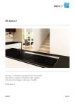
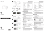


![004770261 [IT GB DE] Clemy v.112008.indd](http://vs1.manualzilla.com/store/data/006104403_1-1997af9356d214347c2fb950650381db-150x150.png)