1
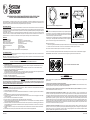
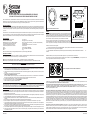
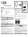
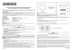
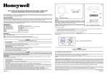
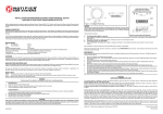
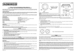
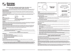
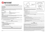
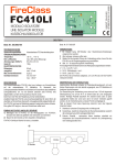
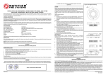
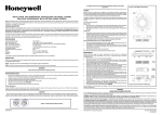
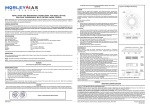
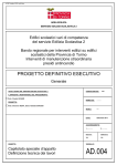
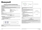
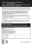
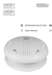
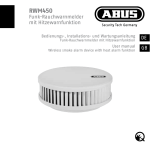
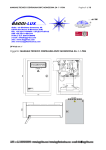
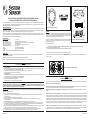
SENSOR
COVER
LED2
INSTALLATION AND MAINTENANCE INSTRUCTIONS FOR MODEL 2251ME
ANALOGUE ADDRESSABLE PHOTOELECTRONIC SMOKE SENSOR
COVER
REMOVAL TABS
LED1
Before installing the sensor, please thoroughly read System Sensor’s wiring and installation manual, I56-407-XX, Guide for Proper Use of System
Sensor Smoke Detectors. This manual includes detailed information on sensor spacing, placement, zoning and special applications. Copies of
this manual are available at no charge from System Sensor.
Painted
surface
GENERAL DESCRIPTION
Model 2251ME analogue addressable photoelectronic sensors are plug-in type smoke sensors that combine a photoelectronic sensing chamber
with addressable-analogue communications. These sensors are designed for open area protection and must only be connected to control panels
that use a compatible proprietary analogue addressable communciation protocol for monitoring and control.
SENSOR
SCREEN
net
Mag
Test
SENSING
CHAMBER
Figure 1. Test Magnet Positioning
TESTING
Sensors must be tested after installation and following periodic maintenance. However,
before testing, notify the proper authorities that the smoke detector system is undergoing
maintenance and the system will be temporarily be out of service. Disable the zone or
system undergoing maintenance to prevent unwanted alarms.
Two LEDs on each sensor light to provide a local 360o visible sensor indication. The LEDs can be latched on by code command from the control
panel for an alarm indication. They can also be unlatched to the normal condition by code command. Remote LED indicator capability is available
as an optional accessory wired to the standard base terminals.
SPECIFICATIONS
Operating Voltage Range
15 to 32 VDC
Max. Standby Current
230 µA @ 24 VDC (no communication)
Max. Avg. Standby Current
330 µA (one communication every 5 sec. with LED blink enabled)
Max. Alarm Current (LED on)
6.5 mA @ 24 VDC
Operating Humidity Range:
10% to 93% Relative Humidity, noncondensing
Operating Temperature Range
-30oC to 80oC
Height:
43 mm installed in B501 Base
Diameter:
102 mm installed in B501 Base
Weight:
115 g
This detector has been independently tested and certified to prEN54 part 7.
In addition, check to ensure that the LEDs blink (if this feature is operational under software
command). If they do not, power has been lost to the sensor (check the wiring) if it is
defective (return it for repair).
Figure 2. Sensor with Cover Removed
Test the sensors as follows:
1.
Test the sensor by positioning the test magnet (Model M02-04-optional) against the sensor body approximately 2cm from LED1 in the
direction of the metering socket as shown in Figure 1.
2.
Both LEDs should latch on within 30 seconds indicating an alarm and activating the panel.
After completion of this test notify the proper authorities that the system is operational.
WIRING GUIDE
Refer to the installation instructions supplied with the plug-in sensor bases for wiring details. All bases are provided with terminals for power
and an optional Remote Indicator.
Sensors that fail this test shoud be cleaned as described under MAINTENANCE and retested. If the sensors still fail this test they should be
returned for repair.
NOTE: All wiring must conform to applicable local and national codes and regulations.
NOTE: Verify that all sensor bases are installed and that polarity of the wiring is correct at each base.
WARNING
Disconnect loop power before installing sensors.
a.
b.
c.
d.
e.
f.
5
4
3
2
Sensor Installation
Set the sensor address (see Figure 3) by using a flat blade screwdriver to turn the two rotary switches, selecting the desired number between
01 and 99. Record the address on the label attached to the base.
Insert the sensor into the base and rotate it clockwise with gentle pressure until it drops into place.
Continue to rotate the sensor until it locks into the base.
Tamper-Resistance
Model 2251ME includes a feature that, when activated, prevents removal of the sensor without the use of a tool. Refer to the installation
instructions for the sensor base for details of how to use this feature.
After all the sensors have been installed, apply power to the system.
Test the sensor as described under TESTING.
Reset the sensor by communication command from the panel.
6 7 8 9
1 0
TENS
5
4
3
2
6 7 8 9
Figure 3. Rotary Decade Address Switches
1 0
ONES
WARNING
LIMITATIONS OF SMOKE DETECTORS
This smoke detector is designed to activate and initiate emergency action, but will do so only when used in conjunction with other equipment.
Smoke detectors will not work without power.
CAUTION
Dust covers help to protect units during shipping and when first installed. They are not intended to provide complete protection against
contamination therefore sensors should be removed before construction, major re-decoration or other dust producing work is started.
Dust covers must be removed before system can be made operational.
Smoke detectors will not sense fires which start where smoke does not reach the detectors. Smoke from fires in chimneys, in walls, on
roofs, or on the other side of closed doors may not reach the smoke detector and trigger the unit.
A detector may not detect a fire developing on another level of a building. For this reason, detectors should be located on every level for a
building.
MAINTENANCE
Before cleaning, notify the proper authorities that the system is undergoing maintenance and will be temporarily out of service. Disable the
system to prevent unwanted alarms.
1.
2.
Remove the sensor to be cleaned from the system.
Remove the sensor cover. Use a small flat blade screwdriver to gently release each of the four cover removal tabs that hold the cover in
place (see Figure 2).
3.
Vacuum the outside of the screen carefully without removing it.
4.
Remove the sensor screen. Pull the screen straight away from the sensing chamber until it snaps out of place. Replacement
screens are available.
5.
Remove the chamber cover by pulling it gently away from the sensing chamber until it snaps out of place.
6.
Use a vacuum cleaner and/or clean, compressed air to remove dust and debris from the sensing chamber and sensing chamber cover.
7.
Re-install the sensing chamber cover by aligning the arrow moulded on the cover with the arrow printed on the circuit board and sliding
the cover over the chamber, gently pressing it home until it until it snaps into place.
8.
Re-install or replace the sensing chamber screen by sliding it over the sensing chamber. Rotate the screen until the locating tabs on the
bottom rim locate in the cutouts in the chamber base, and the top of the screen is flush with the top of the chamber.
9.
Re-install the sensor cover. Use the cover removal tabs and LEDs to align the cover with the sensor. Snap the cover into place.
10. When all sensors have been cleaned, restore power to the loop and test the sensor(s) as described under TESTING.
Smoke detectors also have sensing limitations. Ionization detectors offer a broad range fire-sensing capability, but they are better at detecting
fast, flaming fires than slow smouldering fires. Photoelectronic detectors sense smouldering fires better than flaming fires. Because fires develop
in different ways, and are often unpredictable in their growth, neither type of detector is necessarily better and a given detector may not always
provide warning of a fire. In general, detectors cannot be expected to provide warnings for fires resulting from inadequate fire protection practices,
violent explosions, escaping gas, improper storage of flammable liquids like cleaning solvents, other safety hazards, or arson. Smoke detectors
used in high air velocity conditions may fail to alarm due to dilution of smoke densities created by such frequent and rapid air exchanges.
Additionally, high air velocity environments may create increased dust contamination, demanding more frequent maintenance.
Smoke detectors cannot last forever. Smoke detectors contain electronic parts. Even though detectors are made to last over 10 years, any of
these parts could fail at any time. Therefore, test your smoke detector system at least semiannually. Clean and take care of your smoke detectors
regularly. Taking care of the fire detection system you have installed will significantly reduce your product liability risks.
Pittway Tecnologica S.p.A., Via Caboto 19, 34147 Trieste, Italia
D600-04-00
1
© System Sensor 2000
I56-1273-004
LED2
CALOTTA
RIMOVIBILE
ISTRUZIONI DI INSTALLAZIONE E MANUTENZIONE DEL RIVELATORE DI FUMO
FOTOELETTRONICO INDIRIZZABILE ANALOGICO MODELLO 2251ME
LAMELLE DI
FISSAGGIO
LED1
Prima dell’installazione, si consiglia di leggere per intero il manuale di installazione e di collegamento I56-407-XX, Guide for Proper Use of
Smoke Detectors. Questo manuale include informazioni dettagliate sul distanziamento dei sensori, sul loro posizionamento, suddivisione in zone
e applicazioni particolari. Copie del manuale sono disponibili gratuitamente presso System Sensor.
Superfice
colorata
Figura 1. Posizionamento del Magnete nel Test
DESCRIZIONE GENERALE
I sensori fotoelettronici indirizzabili analogici modello 2251ME sono rivelatori di fumo ad innesto sulla base che combinano una camera ottica
sensibile al fumo ed un dispositivo di comunicazione analogico indirizzabile. Tali sensori sono progettati per la protezione di aree aperte e devono
venire collegati solo a pannelli di controllo funzionanti con protocollo di comunicazione proprietario compatibile di tipo analogico ad indirizzi per
il monitoraggio e il controllo.
Due led posti su ciascun sensore sono in grado di lampeggiare, offrendo visibilità a 360°. I led possono venire accesi con un apposito comando
dal pannello di controllo in condizioni di allarme. Allo stesso modo possono venire spenti in condizioni di normalità con un altro comando. La
possibilità di usufruire di un led remoto viene offerta come accessorio opzionale da collegare ai terminali della base standard.
TEST
I sensori devono venire testati dopo la loro installazione e dopo le periodiche operazioni
di manutenzione. In ogni caso, prima di effettuare il test, notificare alle autorità competenti che il sistema in manutenzione si trova temporaneamente fuori servizio. Disabilitare
il sistema antincendio per impedire allarmi accidentali.
Inoltre assicurarsi che i led lampeggino (se tale operazione è stata attivata via software).
In caso negativo, il difetto può risiedere nell’alimentazione (controllare i collegamenti)
oppure nel sensore stesso (rivolgersi al Servizio Assistenza Clienti).
SPECIFICHE
Tensione di funzionamento
da 15 a 32 V c.c.
Massima corrente di standby
230 µA @ 24 V c.c. (senza comunicazione)
Corrente media di standby
330 µA (un’interrogazione ogni 5 s con lampeggio)
Massima corrente d’allarme (led accesi)
6.5 mA @ 24 V c.c.
Campo di umidità di funzionamento
da 10% a 93% umidità relativa
Temperatura di funzionamento
da -30°C a 80°C
Altezza:
43 mm con base B501
Diametro:
102 mm con base B501
Peso:
115 g
Questo rivelatore di fumo è stato testato indipendentemente e certificato prEN54 parte 7.
d.
e.
f.
I sensori che non dovessero superare questo test dovrebbero essere sottoposti a manutenzione secondo le modalità descritte al paragrafo
MANUTENZIONE e testati nuovamente. Se il test avesse ancora esito negativo, rivolgersi al Servizio Assistenza Clienti.
5
4
3
2
Installazione del sensore
Impostare l’indirizzo del sensore (vedi Figura 3) ruotando con un cacciavite i 2 selettori e scegliendo l’indirizzo desiderato tra 01 e 99.
Scrivere l’indirizzo scelto sull’apposita etichetta posta sulla base.
Inserire il sensore nella base con una leggera pressione, ruotando il dispositivo in senso orario finché non entra nella base stessa.
Continuare a ruotare il sensore finché non si incastra nella base.
Dispositivo di protezione anti-manomissioni
Le basi dei rivelatori includono un dispositivo di sicurezza che, se attivato, impedisce la rimozione del sensore senza un apposito strumento.
Fare riferimento al manuale d’istruzioni della base per maggiori dettagli sull’uso di questo dispositivo.
Dopo che tutti i sensori sono stati installati, ripristinare l’alimentazione.
Effettuare il test indicato al paragrafo TEST.
Effettuare un reset mediante apposito comando dal pannello di controllo.
6 7 8 9
1 0
TENS
5
4
3
2
6 7 8 9
Figura 3. Selettori di Indirizzo Rotanti a Decadi
1 0
ONES
AVVERTENZE
LIMITAZIONI DEI RIVELATORI DI FUMO
ATTENZIONE
Le protezioni antipolvere fornite proteggono il sensore durante il trasporto e prima dell’installazione. Esse non sono destinate a garantire una completa protezione da contaminazioni esterne; pertanto i sensori dovrebbero venire tolti prima dell’esecuzione di lavori di
muratura, di manutenzione degli ambienti o comunque di interventi in grado di produrre polveri. Le protezioni antipolvere devono
essere rimosse prima di rendere operativo il sistema antincendio.
Questo rivelatore di fumo è progettato per attivare le procedure di emergenza, ma è in grado di farlo solo quando viene collegato ad altre
apparecchiature.
I rivelatori di fumo non funzionano in assenza di energia elettrica.
I rivelatori di fumo non rivelano incendi che si sviluppano in luoghi lontani dal luogo di installazione. Il fumo derivante da incendi in camini,
pareti, tetti oppure dietro una porta chiusa può non essere rilevabile dal rivelatore.
MANUTENZIONE
Prima di effettuare la manutenzione, notificare alle autorità competenti che il sistema in manutenzione si trova temporaneamente fuori servizio.
Disabilitare il sistema antincendio per impedire allarmi accidentali.
Un sensore può non rilevare un incendio che si sviluppa su un piano dell’edificio diverso da quello di installazione. Per questo motivo i
rivelatori dovrebbero essere installati su ciascun piano.
1.
2.
Rimuovere dalla sua base il sensore da pulire.
Rimuovere la calotta del sensore. Per farlo è sufficiente sollevare delicatamente con un cacciavite le 4 linguette che fissano la calotta al
sensore.
3.
Aspirare delicatamente la superficie esterna della retina senza toglierla dal sensore.
4.
Rimuovere la retina di protezione della camera ottica. Sollevare la retina verso l’alto finché non esce dal suo alloggiamento. Sono disponibili retine di ricambio.
5.
Aprire la camera ottica, sollevando delicatamente il copricamera.
6.
Aspirare o rimuovere con un getto d’aria polvere e detriti dalla camera ottica e dal copricamera.
7.
Reinserire il copricamera allineando la freccia impressa sulla parte superiore con la freccia impressa sul circuito stampato, riposizionare
la camera premendo delicatamente fino allo scatto.
8.
Reinstallare o sostituire la retina infilandola sulla camera ottica. Ruotare la retina di protezione finchè i dentelli di aggancio alla base non
entrano perfettamente nelle corrispondenti cavità della camera ottica e la parte superiore della retina non risulta a filo con la parte superiore della camera ottica.
9.
Rimettere la calotta. Servirsi dei fori per i led come riferimenti per allineare la calotta al sensore. Premere la calotta fino a far scattare le
linguette.
10. Quando tutti i sensori sono stati puliti, riattivare il sistema e testare i sensori come descritto al paragrafo TEST.
D600-04-00
Figura 2. Sensore con Calotta Rimossa
Alla fine del test notificare alle autorità competenti che il sistema è di nuovo operativo.
AVVERTENZA
Sconnettere l’alimentazione dalla linea prima di procedere all’installazione dei sensori
b.
c.
CAMERA
RILEVAZIONE
Effettuare il test come segue:
1.
Posizionare il magnete (Accessorio M02-04, opzionale) sul bordo del sensore a circa 2 cm dal LED 1 di Figura 1, vicino alla porta MOD.
2.
Attendere che entro 30 secondi entrambi i led si illuminino, indicando l’allarme e attivando il pannello di controllo.
COLLEGAMENTI ELETTRICI
Fare riferimento al manuale d’istruzioni delle basi dei sensori per i dettagli sugli schemi di collegamento. Tutte le basi sono fornite di terminali di
alimentazione e di indicatore remoto opzionale.
NOTE: tutti i collegamenti devono essere conformi alle disposizioni di legge in materia. Verificare che tutte le basi dei sensori siano installate
correttamente e che la polarità di ciascuna sia corretta.
a.
RETINA
RIMOVIBILE
net
Mag st
Te
I rivelatori di fumo presentano inoltre limitazioni di sensibilità. I rivelatori a camera di ionizzazione coprono una vasta gamma di tipi
d’incendio, ma si prestano meglio alla rilevazione di incendi che si sviluppano velocemente e con fiamme piuttosto che di focolai d’incendio a
lento sviluppo. I rivelatori ottici sono più sensibili ad incendi a lento sviluppo, che ad incendi improvvisi. Dato che gli incendi si possono sviluppare
in modalità diverse e sono spesso imprevedibili nel loro sviluppo, nessun tipo di rivelatore può essere considerato il migliore in assoluto ed offrire
garanzie assolute di protezione. In generale, i rivelatori non sono in grado di offrire protezione da incendi derivanti da procedure antincendio
inadeguate, esplosioni improvvise, fughe di gas, depositi impropri di liquidi infiammabili, come i solventi chimici, mancato rispetto delle norme di
sicurezza o incendi dolosi. I rivelatori di fumo installati in condizioni di forti correnti d’aria possono non segnalare tempestivamente un allarme a
causa della bassa densità di fumo provocata dal continuo ricambio d’aria. Inoltre ambienti di questo tipo possono venire più facilmente contaminati da polveri, richiedendo una manutenzione più frequente.
I rivelatori di fumo hanno una vita limitata. I rivelatori di fumo contengono componenti elettronici. Sebbene i rivelatori siano costruiti per
garantire più di 10 anni di vita, uno qualsiasi di questi componenti potrebbe essere soggetto a guasti. Di conseguenza si consiglia di testare i
rivelatori almeno ogni 6 mesi. La manutenzione e pulizia dei rivelatori va eseguita regolarmente. Una manutenzione accurata del sistema
antincendio installato ridurrà significativamente il rischio di inconvenienti.
© System Sensor 2000
Pittway Tecnologica S.p.A., Via Caboto 19, 34147 Trieste, Italia
2
I56-1273-004
CUBIERTA
EXTRAIBLE
LED2
INSTRUCCIONES DE INSTALACIÓN Y MANTENIMIENTO DEL SENSOR
DE HUMO ÓPTICO ANALÓGICO DIRECCIONABLE MODELO 2251ME
LENGUETAS PARA
EXTRAER LA TAPA
Antes de instalar el sensor, lea detenidamente el manual de conexión e instalación de System Sensor, I56-407-XX, Guía Para el Uso Adecuado
Detectores de Humo. Dicho manual contiene información detallada sobre la distancia, ubicación, tipo de zonas y aplicaciones especiales del
sensor. Pueden obtenerse copias de este manual sin cargo, previa solicitud a System Sensor.
LED1
Superficie
Pintada
DESCRIPCIÓN GENERAL
Los sensores ópticos analógicos direccionables modelo 2251ME son detectores de conexión que combinan una cámara de detección fotoelectrónica
con comunicaciones analógicas direccionables. Se han diseñado dichos sensores para la protección de zonas diáfanas y sólo deben conectarse
a cuadros de control que empleen un protocolo propio de comunicacines que sea compatible y direccionable analógicamente para la supervisión
y el control.
Figura 1. Ubicación del Imán de Prueba
de 15 a 32 Vdc
230 µA @ 24 Vdc (sin comunicación)
330 µA (comunicaciones cada 5 seg. con el LED intermitente activado)
6,5 mA @ 24 Vdc
Humedad Relativa del 10% al 93%, sin condensar
de -30°C a 80°C
43 mm instalado en Base B501
102 mm instalado en Base B501
115 g
y certificado según prEN54 parte 7.
Figura 2. Sensor con la Tapa Retirada
Asimismo, compruebe para asegurarse de que parpadeen los LED (si funcionan bajo
comando de software). De lo contrario, significa que se ha perdido el suministro eléctrico
al sensor (compruebe el conexionado), si está defectuoso, devuélvalo para su reparación.
Pruebe los sensores de la forma siguiente:
1.
Pruebe el sensor situando el imán de prueba (Modelo M02-04 - opcional) al lado de la carcasa exterior a unos 2 cm de distancia del
LED1 en dirección al enchufe, según se indica en la Figura 1.
2.
Ambos LED deberán enclavarse dentro de un plazo de 30 segundos, indicando una alarma y activando la señal de alarma en la Central
Incendios.
GUÍA PARA LA CONEXIÓN
Véanse las instrucciones de instalación suministradas con las bases conectadas si desea más detalles acerca del conexionado. Todas las bases
están dotadas de terminales de suministro eléctrico y un Indicador Remoto opcional.
Los sensores que no pasen dichas pruebas deberán limpiarse según se detalla en el epígrafe MANTENIMIENTO y volver a probarse. Si los
sensores siguen fallando, deberán devolverse para su reparación.
ADVERTENCIA
Desconecte el suministro eléctrico de lazo antes de instalar los sensores.
b.
c.
d.
e.
f.
5
4
3
2
Instalación del Sensor
Fije la dirección del sensor (véase Figura 3) mediante un destornillador de hoja plana para girar ambos interruptores, seleccionando el
número deseado del 01 al 99. Anote la dirección sobre la etiqueta situada en la base.
Coloque el sensor en la base y gírelo presionando suavemente en sentido de las agujas del reloj hasta que éste se encuentre en la posición
correcta.
Siga girando el sensor hasta que quede bien acoplado.
Opción de seguridad Antimanipulaciones
El modelo 2251ME dispone de una opción que, si es utilizada, impide que se retire el sensor si no es mediante el uso de herramientas.
Para hacer uso de esta opción consulte el manual de instrucciones para la instalación de la base del detector.
Tras haber instalado los detectores, conecte la alimentación a la central del panel.
Pruebe el sensor según se indica en el epígrafe PRUEBAS.
Rearme el detector en el panel de control del sistema.
6 7 8 9
1 0
TENS
5
4
3
2
6 7 8 9
Figura 3. Interruptores Giratorios de Dirección Decádicos
1 0
ONES
ADVERTENCIA
LIMITACIONES DE LOS DETECTORES DE HUMO
El detector de humo está diseñado para activar e iniciar acciones de emergencia, pero sólo lo hará si se emplea conjuntamente con otros
equipos. Los detectores de humo no funcionarán sin suministro eléctrico.
Los detectores de humo no detectarán incendios que se inician en un lugar donde el humo no llegue a los detectores. Puede que el humo
procedente de chimeneas, paredes o tejados o al otro lado de puertas cerradas no llegue al detector de humo y no dispare la unidad.
Un detector no podrá detectar un incendio que se esté produciendo en otra planta del edificio. Por esta razón, los detectores se deben
colocar en todas las plantas del edificio.
PRECAUCIÓN
Los protectores para el polvo ayudan a proteger las unidades durante el transporte y en su instalación inicial. No se pretende que ofrezcan
protección total contra todo tipo de contaminación, por lo que antes de iniciarse cualquier construcción, decoración u otra actividad causante de
polvo, los detectores deben ser retirados. También se debe extraer esta protección antes de la puesta en marcha del sistema.
MANTENIMIENTO
Antes de limpiar los equipos, avise al personal responsable que se está realizando el mantenimiento del sistema y que éste permanecerá
momentáneamente fuera de servicio. Anule los equipos sobre los cuales va ha realizar el mantenimiento para prevenir alarmas no deseadas.
Los detectores también tienen ciertas limitaciones de detección. Los detectores iónicos poseen un alto nivel de detección de incendios,
pero detectan mejor los incendios rápidos con llamas que los incendios lentos sin llama. Los detectores ópticos detectan mejor los incendios sin
llama que los de llama. Dado que los incendios se desarrollan de formas distintas, y con frecuencia son imprevisibles en cuanto a su desarrollo
ningún tipo de detector, necesariamente resulta ser el mejor y un determinado detector no siempre podrá advertir la presencia de un tipo
específico de fuego. En general, no se puede esperar que los detectores proporcionen señales de alarma en caso de incendios resultantes de
prácticas inadecuadas de protección contra incendios, explosiones violentas, explosiones de gas, almacenamiento impropio de líquidos combustibles
como disolventes de limpieza, otros peligros que atenten contra la seguridad, o incendios intencionados. Los detectores de humo utilizados en
condiciones ambientales donde la velocidad del viento es muy elevada podrán no disparar alarmas debido a la dilución las densidades de humo
originadas por frecuentes y rápidos cambios de aire. Además, en condiciones medioambientales donde es frecuente una velocidad de aire
bastante alta, se incrementa la contaminación por presencia de polvo, y se requiere entonces realizar las tareas de mantenimiento del detector
con mayor frecuencia.
1.
2.
3.
4.
Extraiga el sensor que vaya a limpiar.
Extraiga la tapa del sensor. Utilice un destornillador plano y pequeño para desplazar las cuatro lengüetas que sujetan la tapa. (ver Figura 2)
Limpie cuidadosamente la parte exterior de la pantalla de protección sin extraerla.
Extraiga la pantalla protectora del sensor: estire de la pantalla hasta separarla de la cámara del sensor. Existen pantallas protectoras de
recambio.
5. Extraiga la tapa de la cámara tirando de ella lentamente para separarla de la cámara sensora.
6. Utilice un aspirador o compresor de aire para eliminar las partículas de polvo y suciedad de la cámara del sensor y de su tapa.
7. Vuelva a instalar la tapa de la cámara haciendo coincidir la flecha de la tapa con la flecha impresa en la placa de circuito. Gire la tapa sobre
la cámara presionando suavemente hasta que se coloque en su sitio.
8. Vuelva a instalar o sustituya la pantalla de la cámara sensora girando la pantalla sobre la cámara hasta que las lengüetas encajen en la base
de la cámara y la parte superior de la pantalla coincida con la parte superior de la cámara.
9. Vuelva a instalar la tapa del sensor. Utilice las lengüetas de la tapa y los LEDS para alinear la tapa con el sensor. Encaje la tapa en su sitio.
10. Cuando finalice la limpieza de todos los sensores, vuelva a conectar los equipos y compruebe su funcionamiento tal y como se describe en
el procedimiento de prueba.
Los detectores de humo tiene una duración limitada. Los detectores de humo contienen componentes electrónicos. A pesar de que los
detectores se fabrican para que duren más de diez años, cualquiera de sus componentes podría fallar en cualquier momento. Por lo tanto,
pruebe su sistema de detectores de humo como mínimo cada seis meses. Limpie y cuide sus detectores de humo de forma periódica. El
mantenimiento del sistema de detección instalado reducirá notablemente los riesgos de malfuncionamiento.
Pittway Tecnologica S.p.A., Via Caboto 19, 34147 Trieste, Italia
D600-04-00
de
Realizadas todas las pruebas, notifique a las autoridades competentes que el sistema está en funcionamiento.
NOTA: Todo el conexionado deberá cumplir la normativa y los reglamentos locales y nacionales aplicables.
NOTA: Verifique que todas las bases de sensor estén instaladas y que la polaridad del conexionado en cada base sea la correcta.
a.
CAMARA
DIFUSORA
PRUEBAS
Los detectores deben probarse tras su instalación y seguir un mantenimiento periódico.
No obstante, antes de realizar las pruebas, notifique a las autoridades competentes que
el sistema de detectores de humo está realizando tareas de mantenimiento y que el
sistema permanecerá temporalmente fuera de servicio. Desactive la zona o el sistema
que está llevando a cabo el mantenimiento para evitar alarmas no deseadas.
En cada sensor se iluminan dos diodos fotoemisores (LED) indicando la detección desde cualquier punto visible. Se pueden enclavar mediante
una orden procedente de la central. También se pueden desenclavar a estado normal mediante una orden procedente de la central. Se puede
disponer de un LED indicador remoto como accesorio opcional conectado a los terminales de base estándar.
CARACTERÍSTICAS
Límites de Tensión de Funcionamiento
Corriente en Estado de Reposo
Media Máxima de Corriente en Estado de Reposo
Corriente Máxima de Alarma (LED iluminado)
Límites de Humedad de Funcionamiento:
Límites de Temperatura de Funcionamiento
Altura:
Diámetro:
Peso:
Este detector ha sido probado y homologado independientemente
PANTALLA
EXTRAIBLE
net
Mag
Test
3
© System Sensor 2000
I56-1273-004
LED2
MELDER DECKEL
RASTNASEN
INSTALLATIONS- UND WARTUNGSANLEITUNG FÜR DIE ADRESSIERBAREN
EXTREM FLACHEN OPTISCHEN RAUCHMELDER 2251ME
LED1
METALL ABSCHIRMUNG
Markierte
Seite
Allgemeine Beschreibung
Der analoge adressierbare Rauchmelder 2251ME verwendet eine optische Meßkammer nach dem Streulichtprinzip. Dieser Rauchmelder ist nur
für die dafür vorgesehenen Brandmelderzentrale einzusetzen. Er kann in eine Vielzahl von unterschiedlichen Montage-Sockeln eingebaut werden.
Zwei LEDs an jedem Melder ermöglichen eine 360°-Anzeige am Melder, die von der Brandmelderzentrale im Alarmfall oder zur Störungsanzeige
angesteuert werden. Für den Normalbetrieb können sie im Blink-Modus angesteuert werden. Der Anschluß eines Melderparallelindikators zur
abgesetzen Anzeige eines Alarms ist möglich.
Technische Daten
Betriebsspannung:
Max. Ruhestrom:
Max. durchschn. Ruhestrom(arithm.)
Max. Alarmstrom (LED an)
Luftfeuchtigkeit:
Umgebungstemperatur:
Höhe:
Durchmesser:
Gewicht:
net
Mag st
Te
Abb. 1 Positionierung des Testmagneten
MEßKAMMER
Test
Die Melder müssen nach der Installation sowie in regelmäßigen Intervallen getestet
werden. Bevor dies geschieht, müssen vor Ort die verantwortlichen Stellen informiert
werden, daß das Brandmeldesystem überprüft bzw. gewartet wird und demnach nicht
voll einsatzbereit ist. Deaktivieren Sie die externen Alarmierungs- bzw.
Übertragungseinrichtungen, um Fehlalarme zu vermeiden.
15V bis 32V DC
230µA @ 24V DC (ohne Datenaustausch)
330µA (1 Abfrage in 5s mit LED-Blinkmodus)
6,5mA @24V DC
10% bis 93% rel. Luftfeuchtigkeit (nicht kondensierend)
-30°C – +80°C
43mm installiert in Sockel B501
102mm installiert in Sockel B501
115g
Abb. 2 Melder mit abgenommenem Deckel
Zusätzlich sollte an der Zentrale der Gruppentest aktiviert werden; dadurch werden alle
Melder-LEDs dieser Gruppe in den Blink-Modus versetzt. Sollten die LEDs nicht blinken, wurde die Spannungsversorgung unterbrochen
(Verkabelung prüfen) oder der Melder ist nicht programmiert (Adressierung und Programmierung prüfen) oder der Melder ist defekt (Zurücksenden).
Der Melder wird folgendermaßen getestet:
A.
1.
Dieser Rauchmelder wurde nach prEN54 Teil7 getestet und zertifiziert.
2.
Installation
Die Einzelheiten zum Anschluß des Meldersockels sind der Anschlußanleitung der Meldersockel zu entnehmen, die den Sockeln beigefügt sind.
B.
1.
2.
Anmerkung: Die Verdrahtung muß den lokalen Vorschriften und Anforderungen entsprechen.
Stellen Sie sicher, daß die Meldersockel korrekt verdrahtet sind und Kurzschlüsse oder vertauschte Adern auszuschließen sind.
Testmagnet M02-04
Testen Sie den blinkenden Melder indem der Magnet ca. 2cm von LED 1 im Uhrzeigersinn entfernt, direkt an den Melder gehalten wird (s.
Abb.1).
LEDs sollten innerhalb von 30s einen Alarm anzeigen indem sie kontinuierlich leuchten und an der Brandmelderzentrale einen Alarm
auslösen.
Prüfgas
Sprühen Sie mit einem kurzen Druck auf die Auslösevorrichtung etwas Prüfgas in den Melder, ohne ihn aus dem System zu entfernen.
LEDs sollten innerhalb von 30s einen Alarm anzeigen indem sie kontinuierlich leuchten und an der Brandmelderzentrale einen Alarm
auslösen.
Nachdem alle Test- und Wartungsarbeiten durchgeführt worden sind, müssen die zuständigen Stellen informiert werden, daß das System wieder
funktionsfähig ist.
Melder, die verschmutzt sind, sollten gereinigt und dann noch einmal getestet werden, wie unter WARTUNG beschrieben. Wenn der Melder
immer noch nicht korrekt arbeitet, muß er ausgetauscht und zur Reparatur zurück geschickt werden.
Warnung
Bevor die Melder und Sockel installiert werden, sollte die Spannungsversorgung für die Brandmelderzentrale abgeschaltet werden.
Installation der Melder
Stellen sie die Melder-Adresse zwischen 01 und 99 mit einem Schlitzschrauben-dreher an den beiden Drehschaltern ein und
vermerken Sie die Adresse auf dem Etikett auf dem Sockel. (s. Abb. 3)
b.
Drehen Sie den Melder im Uhrzeigersinn mit leichten Druck in den Sockel
c.
Drehen Sie den Melder weiter bis zum Anschlag
Diebstahl-Sicherung
Die Sockel sind mit einer Diebstahlsicherung für die Melder ausgestattet. Mit dieser Sicherung kann der Melder nicht mehr ohne
Werkzeug aus dem Sockel entfernt werden. Näheres dazu finden sie in der Montageanleitung der Sockel.
d.
Nachdem alle Melder installiert sind, schalten Sie die Brandmelderzentrale wieder ein.
e.
Test der ordnungsgemäßen Funktion der Melder wie unter TEST beschrieben
f.
Zurücksetzen der Melder an der Zentrale
Achtung
Die Melder werden mit Staubschutzhauben aus Plastik ausgeliefert, die Verschmutzungen während des Transports und der ersten
Installation verhindern sollen. Die Hauben sind nicht dazu gedacht, die Melder bei großen Staubbelastungen, wie zum Beispiel bei Bohroder Schleifarbeiten, zu schützen. In solchen Fällen sollten die Melder aus dem Sockel entfernt werden. Für eine ordnungsgemäße
Funktion, darf die Plastikhaube nicht montiert sein.
a.
5
4
3
2
5
4
3
2
1 0
TENS
6 7 8 9
Abb. 3 Drehschalter für Adressierung
1 0
ONES
Warnung
Funktionsbeschränkung der Rauchmelder
Wartung
Vor der Reinigung der Melder, müssen die entsprechenden Stellen informiert werden, daß das Brandmeldesystem nicht voll einsatzfähig ist.
Deaktivieren sie die externen Alarmierungs- bzw. Übertragungseinrichtungen.
1. Entfernen Sie die zu reinigenden Melder aus dem System.
2. Entfernen Sie den Deckel des Melders. Benutzen Sie dazu einen kleinen Schlitzschraubendreher, der die 4 Rastnasen des Deckels
öffnen kann (s. Abb. 2)
3. Entfernen Sie Schmutz und Staub von dem Abschirmungsgitter ohne dieses zu entfernen.
4. Entfernen Sie jetzt die Abschirmung durch Abziehen des Gitters von der Melderkammer, bis das Gitter ausrastet. Austauschgitter sind
verfügbar.
5. Entfernen Sie jetzt die Abdeckung der Melderkammer durch Abziehen der Abdeckung, bis es ausrastet.
6. Benutzen Sie einen Staubsauger und/oder Druckluft um Staub und Schmutz aus der Melderkammer und Melderkammerabdeckung zu
entfernen. Stellen Sie sicher, daß die Druckluft öl- und fettfrei ist und reduzieren Sie die Druckluft auf 1,5 bar, um Beschädigungen am
Melder zu vermeiden.
7. Montieren Sie die Melderkammerabdeckung wieder so über die Melderkammer, daß sich der Pfeil auf der Abdeckung und der Pfeil auf der
Platine gegenüberstehen. Drücken Sie die Abdeckung in Richtung der Melderkammer, bis es einrastet.
8. Montieren bzw. tauschen Sie das Insektengitter aus, indem Sie es drehen bis die Nasen sich in den Öffnungen befinden.
9. Montieren Sie den Deckel des Melders wieder. Zur korrekten Ausrichtung benutzen Sie die Rastnasen des Deckels und die Aussparungen
für die Leuchtdioden. Rasten Sie, mit leichtem Druck, den Deckel wieder ein.
10. Nachdem alle Melder gereinigt wurden, installieren Sie diese wieder im System und prüfen sie, wie unter TEST beschrieben.
Dieser Rauchmelder ist entwickelt worden um Gefahrensituationen zu melden und entsprechende Reaktionen auszulösen. Dazu müssen sie mit
anderen Gräten zusammenarbeiten. Rauchmelder funktionieren nicht ohne Spannungsversorgung.
Rauchmelder können kein Feuer melden, wenn der Rauch, den das Feuer erzeugt, den Melder nicht erreicht. Rauch aus Feuern in
Kaminen, in Wänden, auf Dächern oder hinter geschlossenen Türen können den Rauchmelder nicht erreichen und diesen auch nicht auslösen.
Ein Rauchmelder in einer Etage eines Gebäudes kann kein Feuer in einem anderen Stockwerk melden. Aus diesem Grund sollten in
jedem Stockwerk Rauchmelder installiert sein.
Die Empfindlichkeit von Rauchmeldern ist beschränkt. Ionisationsrauchmelder haben eine breitbandiges Detektionsspektrum und sind am
besten geeignet für schnell ausbreitende, lodernde Brände. Optische Rauchmelder dagegen sind besser für die Erkennung von Schwelbränden
geeignet. Da sich ein Brand auf unterschiedliche Weise entwickeln kann und in seiner Ausbreitung oft nicht vorhergesagt werden kann, gibt es
keine generellen Empfehlungen bei der Wahl der Rauchmelder. Ebenso können für einen Einsatzort „falsche“ Rauchmelder einen Brand nicht
zuverlässig melden. Allgemein läßt sich sagen, daß Brände, die durch falsche Brandschutzmaßnahmen, Explosionen, entweichendes Gas, nicht
ordnungsgemäße Lagerung von brennbaren Flüssigkeiten oder Brandstiftung hervorgerufen wurden, nicht frühzeitig erkannt werden können. Bei
Rauchmeldern, die in Umgebungen mit hoher Luftbewegung eingesetzt werden, kann es vorkommen, daß Brände nicht gemeldet werden, da die
Rauchpartikel durch Verwirbelungen nicht bis zum Rauchmelder gelangen können. Außerdem erzeugt die hohe Luftgeschwindugkeit eine stärkere
Verschmutzung, die es erforderlich macht, diese Rauchmelder öfter zu warten.
Rauchmelder halten nicht ewig: Rauchmelder enthalten elektronische Bauteile. Obwohl die Melder für eine Lebensdauer von über 10
Jahren ausgelegt sind, können Defekte an den Bauteilen jederzeit auftreten. Aus diesem Grund, sollten die Melder mindestens halbjährlich
gewartet werden. Regelmäßige Wartung erhöht die Zuverlässigkeit des Brandmeldesystems.
Pittway Tecnologica S.p.A, Via Caboto 19, 34147 Trieste, Italy
© System Sensor 2000
4
D600-04-00
6 7 8 9
I56-1273-004