1
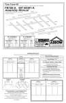
MANUAL DE INSTALACIÓN PALANCA DYNAMIC COD.:
* * * Lea atentamente este manual antes de proceder al montaje * * *
23199
23200
COMPROBACIÓN DEL EMBALAJE
Comprobar que los componentes del modelo elegido se encuentran en
buen estado.
INSTALACIÓN
1. Elegir el emplazamiento adecuado teniendo en cuenta lo siguiente :
Las medidas de la palanca.
Las cotas mínimas de seguridad recomendadas.
Las cotas mínimas de profundidad de la piscina.
2. Para una correcta y sólida fijación al suelo, debe proveerse una
zona hormigueada como cimentación.
3. Realizar los agujeros para la fijación de la parte posterior y anterior
según se indica en la teniendo en cuenta el emplazamiento
deseado de la palanca.
4. Colocar los anclajes posterior en el agujero indicado (fig. 1).
POS.
CÓDIGO
DESCRIPCIÓN
COTA A
1
18541-0100 BARANDILLA DYNAMIC
2
23199-1000 PLATAFORMA DYNAMIC
2 mts
2
23200-1000 PLATAFORNA DYNAMIC
2,3 mts
5. Poner el hormigón y esperar a que fragüe.
6. Una vez el hormigón ha fraguado realizar los taladros con broca de
diámetro 12 mm. correspondientes a la sucesión anterior y colocar
los tacos.
7. Colocar las gomas protectoras que unen la base con el resto de la
barandilla.
8. Montar previamente las partes soporte de la barandilla y la base de
la palanca (Pos. 3).
MANTENIMIENTO
Comprobar regularmente:
1. El buen estado de las fijaciones al suelo y de la estructura y
apretándolas si es necesario.
2. El estado de las gomas de protección. No permita que la
plataforma (Pos. 2) entre en contacto directo con la estructura.
3. El buen estado de las bandas antideslizantes frontales
9. Colocar la estructura montada en su emplazamiento y fijarla (se
adjunta tornilleria) al anclaje posterior sin apretar demasiado.
10.Fijar la estructura montada por su parte anterior antavesándola con
el anillo cóncavo y apretando para que el taco anteriormente ya
montado se expansione y quede fijo.
11.Fijar el travesaño y la base de la barandilla por su parte posterior.
Encarar el montaje de la barandilla y la base de la palanca
perpendicularmente ). Al roscar las 2 piezas se unirán.
12.Montar las barandillas (Pos. 1) encajándolas con la estructura y
fijarlas usando la tornilleria que se adjunta.
13.Colocar la plataforma (Pos. 2) sobre la base de la barandilla y
encarar los agujeros para pasar los tornillos M14x120. Asegurarse
de que se han colocado las 4 gomas protectoras.
14.Colocar las tiras antideslizantes autoadhesivas en el alojamiento de
la extremidad de la pista.
15.Apriete todas las fijaciones y compruebe la seguridad del montaje.
4. Que no se presenten salientes que puedan provocar cortes o
rozaduras a los bañistas.
5. Limpiar la palanca (pista y estructura) con agua y detergente
evitando que este no gotee hacia la piscina.
ADVERTENCIAS DE SEGURIDAD
No demorar la reparación o substitución de cualquier parte dañada
que pueda ser causa de un accidente.
Respetar las normas existentes en cada país con relación al
emplazamiento y cotas de seguridad.
CONSEJOS PARA EVITAR ACCIDENTES
Asegurarse de que esta despejada de bañistas la zona de
seguridad antes de saltar.
No debe saltar ni situarse en el extremo más de 1 persona.
Una vez terminado el montaje guarde este manual en lugar
seguro por si alguna vez necesita algún recambio
ATENCIÓN: Este producto es exclusivo de uso privado.
INSTALLATION MANUAL DYNAMIC LEVER COD.:
23199 / 23200
* * * Read attentivly this manual befote proceeding to the assembly* * *
CHECKING OF THE PACKING
To verify that the components of the chosen model are in good
condition.
INSTALATION
1. To choose the suitable emplacement bearing the following thing in
mind:
The measures of the lever.
The minimal levels of safety recommended.
The minimal levels of depth of the swimming pool.
2. For a correct and solid fixation to the soil, a zone swarmed as
foundation must be provided.
3. To realize the holes for the fixation of the rear and previous part as
is indicated bearing in mind the wished emplacement of the lever.
4. To place the rear anchorages in the hole indicated (fig. 1).
5. To put the concrete and to hope that it sets.
6. Once the concrete has plotted, realize the drills with reel of diameter
12 mm. Correspondents to the previous succession and to place the
plugs
.
7. To place the protective rubbers that join the base with the
rest of the rail.
.
8. Previously, to mount the parts support of the rail and the base of the
lever (Pos. 3).
9. To place the structure mounted in its emplacement and to fix it (it is
attached tornilleria) to the rear anchorage without being too tight too
much.
10.To fix the mounted structure for its previous part getting across with
the concave ring and being too tight in order that the plug
previously already mounted expands and remains fixed.
11.To fix the rung and the base of the rail for its rear part. To face the
assembly of the rail and the base of the lever perpendicularly. To
coil the 2 pieces will join.
12.To mount the rails (Pos. 1) fitting them with the structure and to fix
them using the screws that are attached.
13.To place the platform (Pos. 2) on the base of the rail and to face the
holes to pass the screws M14x120. Insure yourself that 4 protective
rubbers have been placed.
POS.
CODE
DESCRIPTION
COTA A
1
18541-0100 RAIL DYNAMIC
2
23199-1000 PLATFORM DYNAMIC
2 mts
2
23200-1000 PLATFORM DYNAMIC
2,3 mts
MAINTENANCE
Verify it regularly:
1. The good condition of the fixings to the soil and of the
structure and them being too tight if it is necessary.
2. The condition of the protection rubbers. It is not allowed
the platform (Pos. 2) being in direct contact with the
structure.
3. The good condition of the non-slipping frontal bands
4. That do not appear projections that could cause cuts or
frictions the bathers.
5. To clean the lever (track and structure) with water and
detergent preventing this one does not leak towards the
swimming pool.
SAFETY WARNINGS
Not to delay the repair or substitution of any damaged part
that could be a reason of an accident.
Respect the existing procedure in every country with
relation to the emplacement and safety levels.
ADVICES TO AVOID ACCIDENTS
Insure yourself that the safety zone of bathers is clear
before jumping.You must neither jump nor place in the end
more than 1 person.
Once finished the assembly keep this manual in sure
place for if at some time you need some spare part.
MONTAGEHANDBUCH FÜR DAS SPRUNGBRETT DYNAMIC REF:
* * * Lesen Sie dieses Handbuch sorgfältig durch, bevor Sie mit der Montage beginnen * * *
23199
23200
Scheibe und Mutter M10
Scheibe und Mutter M8
Schutzgummis
Verankerung
ÜBERPRÜFUNG DER VERPACKUNG
Überprüfen Sie, ob alle Komponenten des ausgewählten Modells sich
n einem guten Zustand befinden.
MONTAGE
. Wählen Sie den Standort unter Berücksichtigung der folgenden
Punkte aus:
Die Abmessungen des Sprungbretts.
Die empfohlenen Sicherheitsmindestmaße.
Die Mindesttiefe des Schwimmbeckens.
2. Für die korrekte und sichere Befestigung am Boden muss eine
zementiertes Fundament geschaffen werden.
3. Bohren Sie die Löcher für die hintere und vordere Befestigung, so
wie dies angegeben ist. Bedenken Sie dabei die gewünschte Position
des Sprungbretts.
4. Bringen Sie die hintere Verankerung in der angegebenen Öffnung an
Abb. 1)
5. Betonieren Sie und warten Sie, bis der Beton fest ist.
6. Sobald der Beton fest ist, bohren Sie die Löcher der vorherigen
Reihenfolge entsprechend mit einem Bohrer mit 12 mm Durchmesser
und bringen Sie die Dübel an.
7. Bringen Sie die Schutzgummis an, welche die Basis mit dem Rest
des Geländers verbinden.
POS.
CODE
BESCHREIBUNG
Abmessung A
1
2
18541-0100 GELÄNDER DYNAMIC
23199-1000 PLATTFORM DYNAMIC
2 mts
2
23200-1000 PLATTFORM DYNAMIC
2,3 mts
INSTANDHALTUNG
Überprüfen Sie regelmäßig:
1. Den guten Zustand der Befestigungen am Boden und de
Struktur und ziehen Sie dies e nach, falls dies notwendig ist.
8. Montieren Sie zunächst die Stützen des Geländers und die Basis des
2. Den Zustand der Schutzgummis. Das Sprungbrett (Pos. 2) darf
Sprungbretts (Pos.3)
nicht im direkten Kontakt mit der Struktur sein.
9. Bringen Sie die montierte Struktur an den gewünschten Standort und
befestigen Sie diese (mit dem mitgelieferten Schrauben) an der 3. Den guten Zustand der rutschfesten Streifen vorne.
hinteren Verankerung, ohne die Schrauben zu fest zu ziehen.
4. Dass keine hervorstehenden Stellen vorhanden sind, an denen
0. Befestigen Sie die montierte Struktur an ihrem hinteren Teil mit dem sich die Benutzer schneiden oder stoßen können.
konkaven Ring und drücken Sie diesen fest, so dass der bereits
5. Reinigen Sie das Sprungbrett (Piste und Struktur) mit Wasser
montierte Dübel sich ausdehnt und festhakt.
und Reinigungsmittel. Vermeiden Sie, dass Reinigungsmittel in das
1. Befestigen Sie den Querriegel und die Basis des Geländers hinten. Schwimmbecken gelangt.
Stellen Sie das Geländer vertikal zur Basis des Sprungbretts. Beim
SICHERHEITSHINWEISE
Schrauben werden die beiden Teile miteinander verbunden.
2. Montieren Sie die Geländer (Pos. 1) so, dass sie in die Struktur Ersetzen Sie beschädigte Teile unverzüglich, um Unfälle zu
eingepasst werden und befestigen Sie sie mit den mitgelieferten vermeiden.
Berücksichtigen Sie die Normen des jeweiligen Landes hinsichtlich
Schrauben.
Position und Sicherheitsmaßen.
3. Positionieren Sie das Sprungbrett (Pos. 2) auf der Basis des
Geländers und bringen Sie die Löcher in die korrekte Position, um die RATSCHLÄGE ZUM VERMEIDEN VON UNFÄLLEN
Schrauben M14x120 einzuschrauben. Stellen Sie sicher, dass die 4
Bevor Sie springen, versichern Sie sich, dass sich keine Badenden
Schutzgummis angebracht sind.
im Sprungbereich befinden.
Es sollte niemals mehr als 1 Person springen oder am Ende des
4. Bringen Sie die rutschfesten Aufklebstreifen in der Aufnahme am
Sprungbretts stehen.
Ende des Sprungbretts auf.
Wenn das Sprungbrett montiert ist, bewahren Sie dieses
Handbuch an einem sicheren Ort auf, falls Sie ein Ersatzteil
5. Ziehen Sie alle Befestigungen an und überprüfen Sie, ob das
bestellen müssen.
Sprungbrett sicher montiert ist.
ACHTUNG: Dieses Produkt ist ausschließlich für den Privatgebrauch bestimmt.