1
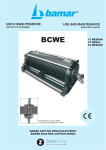
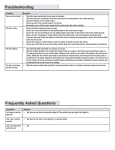
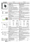
Mod.
1067
DS1067- 058
LBT8997
TASTIERA TOUCH CON LETTORE DI PROSSIMITÁ
TOUCH KEYPAD WITH PROXIMITY READER
Sch./Ref. 1067/026
ITALIANO
DESCRIZIONE GENERALE
Tastiera con frontale in vetro temprato, tecnologia “soft-touch” e display OLED. Essa consente di
comandare e programmare i sistemi della serie 1067, e dispone di un lettore di chiavi di prossimità
1067/332 , di 1 ingresso ausiliare programmabile, e di un microfono per l’ascolto ambientale (da telefono
con interfaccia PSTN o GSM) . Dispone inoltre di un sensore di avvicinamento che permette di attivare le
piene funzionalità del dispositivo che normalmente si trova in uno stato di basso assorbimento;
all’avvicinarsi della mano nell’area sopra il logo, si accende la retroilluminazione, il display visualizza le
informazioni predefinite ed il lettore di chiavi diventa attivo. Dopo 30 secondi dall’ultima azione la tastiera
ritorna nello stato di riposo. Oltre ai normali tasti alfanumerici ed ai tasti di navigazione sono disponibili 4
tasti aggiuntivi le cui funzioni, qualora attivate, saranno visibili per mezzo di icone nell’area del display
immediatamente sovrastante.
POSIZIONAMENTO
La tastiera deve essere posizionata:
• in un ambiente riparato e protetto da acqua e umidità;
• su una parete asciutta e piana;
• in prossimità degli accessi all’area da proteggere;
• in un luogo interno, non soggetto a sbalzi eccessivi di temperatura e
protetto dall’impianto antintrusione;
• a 160 cm di altezza, per le installazioni normali, o a 120 cm di altezza,
per le installazioni adatte a utenti diversamente abili.
CABLAGGIO
La tastiera può essere collegata sul bus a cascata o a stella. La posizione della tastiera lungo il bus non ha
importanza. La lunghezza complessiva di tutte le tratte bus non deve superare 400 metri. Per il cablaggio usare
un cavo schermato a 4 conduttori (2 per l’alimentazione e 2 per il collegamento dati). La sezione dei conduttori
deve essere scelta tenendo conto della caduta di tensione dovuta alla lunghezza del collegamento. Nel conteggio
generale dell’assorbimento dell’impianto considerare anche il consumo max della tastiera (110 mA).
INSTALLAZIONE
La tastiera 1067/026 può essere installata sia a parete sia sopra una scatola da incasso tonda o a 3 posti.
Per installare la tastiera fare quanto segue:
• Sganciare la tastiera dalla staffa a muro facendola slittare (Fig.1).
• Fissare la staffa di supporto alla parete tramite tasselli da 6 mm (non forniti), o sulla scatola da incasso
qualora presente, tenendo la morsettiera verso il basso (Fig.2) utilizzando le predisposizioni “A” o “B”.
Evitare di stringere troppo le viti in quanto la conseguente curvatura della staffa potrebbe rendere
difficoltoso l’aggancio della tastiera alla staffa stessa.
• Per l’antiasportazione utilizzare due tasselli a corredo in corrispondenza dei fori “C” e fissando anche il blocchetto “D”.
• Collegare il cavo alla morsettiera “E”.
• Inserire il cavetto che fuoriesce dalla tastiera sull’apposito connettore “F”. Disporre il cavo in modo tale
che si collochi nell’apposito spazio sul fondo della tastiera per evitare che lo stesso sia pizzicato nella
fase di aggancio della tastiera alla staffa.
• Inserire il blocco tastiera nella staffa e farla scorrere verso il basso.
• Bloccare con la vite di fissaggio “G” (Fig.3).
2
DS1067-058
A
B
C
Fori per fissaggio su scatola da Ø 60
Fori per fissaggio su scatola a 3 posti
Fori per vite protezione antiasportazione
D
Inserto plastico per protezione
antiasportazione
E
F
G
H
Morsettiera di collegamento
Connettore tastiera
Vite di chiusura
Foro per passaggio cavi
Morsetto
+
+D
D
─
+IN
A1
A2
Dettaglio descrizione
BUS Ingresso alimentazione espansione via bus
BUS Trasmissione / ricezione dati
BUS Ingresso alimentazione tastiera via bus
Ingresso ausiliario
Bus fonia
Per la certificazione EN50131 Grado 3 va sempre utilizzato il tassello in posizione C, anche se la tastiera
viene fissata su scatola da incasso. non è obbligatorio per il Grado 2 o inferiore.
COLLEGAMENTO BUS FONIA
Per il collegamento del bus fonia utilizzare un doppino ritorto. Se più tastiere vengono connesse al bus
fonia occorre utilizzare un collegamento a cascata. La lunghezza complessiva del bus fonia non deve
superare 300 metri.
ACQUISIZIONE DELLA TASTIERA
Per l’acquisizione della tastiera touch 1067/026 in fase di prima accensione premere il tasto T4 presente
sul frontale (vedi Fig. 4).
In caso si renda necessario cancellare i parametri della tastiera (Reset), agire nel seguente modo:
• aprire il contatto tamper (sganciare la tastiera dalla relativa staffa)
• premere il tasto T4 per circa 5 secondi.
Per ulteriori informazioni su procedimento di acquisizione fare riferimento al manuale di installazione della
centrale.
DS1067-058
3
INGRESSO DI ALLARME
Collegare un eventuale sensore all’ingresso ausiliare IN1. L’ingresso è riferito a massa (-) e può essere programmato
come NC, NO, Singolo bilanciamento e Doppio bilanciamento. L’ingresso può anche gestire segnali veloci
provenienti da sensori sismici o tapparelle; in questo caso la modalità di collegamento è fissa di tipo NC. Per
realizzare collegamenti con bilanciamento utilizzare resistenze da 2,7 kohm, tolleranza 1% fornite in dotazione.
EN50131
ATTENZIONE: l’unica modalità di collegamento conforme alla normativa EN50131 è quella a “Doppio
Bilanciamento”. Per ulteriori e dettagliate informazioni fare riferimento ai manuali delle centrali 1067.
CARATTERISTICHE TECNICHE
Tensione nominale di alimentazione (prelevati dalla centrale tramite bus)........................................13,8 Vcc
Tensione di funzionamento della tastiera...............................................................................10 Vcc ÷ 15 Vcc
Corrente nominale assorbita a 12 Vcc:
Assorbimento a riposo, solo LED presenza rete ................................................................................... 32 mA
Assorbimento medio, con retroillum. a liv.1........................................................................................... 68 mA
Assorbimento medio, con retroillum. a liv.4......................................................................................... 110 mA
Assorbimento massimo di picco .......................................................................................................... 200 mA
Lunghezza max complessiva della linea Bus Centrale-periferiche ........................................................400 m
Tipo di colloquio......................................................................................................... Seriale protocollo Urmet
Tipo di memoria per il mantenimento della programmazione ....................................................DATA FLASH
Tipo di memoria per il mantenimento del vocabolario................................................................DATA FLASH
Temperatura di funzionamento certificata ................................................................................. -10°C÷ +40°C
Umidità relativa media di funzionamento ..................................................................................................75%
Temperatura di stoccaggio ........................................................................................................ -20°C÷ +60°C
Grado di protezione dell’involucro .................................................................................................. IP40 / IK06
Peso ........................................................................................................................................................460 g
Dimensioni (L x H x P), in mm ............................................................................................... 160 x 130 x 23,5
ATTENZIONE:
1)
2)
3)
4
Informazioni dettagliate e complete sono contenute nei manuali installazione, programmazione e
utente presenti sul CD-ROM fornito a corredo della Centrale, oppure scaricandoli direttamente dal sito
www.urmet.com
NON APRIRE IL CONTENITORE DELLA TASTIERA; tutte le operazioni necessarie all’installazione
e manutenzione del prodotto non richiedono interventi all’interno.
Data la tipologia del prodotto (tasti soft-touch capacitivi) occorre porre attenzione alla pulizia del
frontale in vetro. Per agevolare tale operazione è presente un tasto funzione (tasto T4) che provvede
a bloccare le funzionalità dei tasti per un tempo prefissato di 30 secondi permettendone quindi la
pulizia. Tale tempo sarà scandito a display.
DS1067-058
ENGLISH
GENERAL DESCRIPTION
Keypad with tempered glass front side, “soft-touch” technology and OLED display.
This allows to control and program the 1067 series systems, is equipped with a proximity key reader
1067/332, 1 programmable auxiliary entries and one microphone for environment listening (by phone with
PSTN or GSM interface) . Furthermore, it is provided with a vicinity sensor that allows the activation of full
functionality of the device that is typically in a state of low consumption; placing the hand near the area
above the logo switches on the backlight, the display shows the predefined information and the key reader
becomes active. After 30 seconds from the last action, the keypad returns to standby mode.
Besides the usual alphanumeric and navigation keys, there are 4 additional keys available whose
functions, when activated, are visible by means of an icon on the above display area.
POSITIONING
Keypad must be positioned:
• in an environment that is sheltered and protected from water and
humidity;
• on a dry and level wall;
• in the proximity of the accesses to area to be protected;
• in an inner location which is not subjected to excessive sudden
rises/falls in temperature, and is protected by anti-burglar system;
• at 160 cm height for normal installations, or at 120 cm height for
installations suitable to disabled users.
WIRING
Keypad can be connected on bus either in a cascade or star. Keypad position along bus is not important.
The overall length of all bus sections must not exceed 400 metres. For wiring, use 4 lead screened cable
(2 leads for power supply and 2 leads for data connection). Lead section must be chosen taking into
account voltage drop caused by connection length.
In counting out overall system absorption, also consider max consumption in keypad (110 mA).
INSTALLATION
The 1067/026 keypad can be installed either on a wall or above a round, flush mounting box or 3-seated
built-in case. To install the keypad proceed as follows:
• Remove the keypad from the wall bracket by sliding it (Fig.1).
• Secure the support bracket to the wall with 6 mm plugs (provided), or on the built-in case if available,
keeping the terminal strip downwards (Fig.2) using the mountings “A’ or “B”. Avoid over-tightening the
screws, in that they may cause the bracket to curve, making it difficult to assemble the keypad onto the
bracket itself
• For the anti-removal, use two plugs supplied at the holes "C" and fix also block "D".
• Connect the cable to the terminal board “E”.
• Insert the cable that comes out of the keypad into the dedicated connector “F”. Place the cable so that
it fits into the specially designed space at the bottom of the keypad; this prevents it from being crimped
when assembling the keypad to the bracket.
• Insert the keypad block in the bracket and slide it downwards.
• Secure with locking screws “G” (Fig.3).
DS1067-058
5
Terminal
board
A
Holes for fixing on the box of Ø 60
B
C
D
E
F
G
H
Holes for fixing on a 3-seated box
Holes for anti-dropping protection screw
Plastic insertion for anti-dropping protection
Connection terminal board
Keypad connector
Closing screw
Hole for cable transit
+
+D
D
─
+IN
A1
A2
Description detail
BUS Expansion input supply via bus
BUS Transmission / data receipt
BUS Keypad input supply via bus
auxiliary input
Audio Bus
For EN50131 Degree 3 classification, always use the anchor bolt in position C, even if the keypad is fixed
to a flush-mounting box. This requirement is not mandatory for Degree 2 or lower installations.
AUDIO BUS CONNECTION
For audio bus connection, use twisted duplex cable. If more Keypads are connected to telephony bus, a
cascade connection has to be used. Audio bus overall length must not exceed 300 metres.
CONTROL PANEL
KEYPAD
1067/012A
speech
synthesis
board
AUDIO BUS
BUS POWER SUPPLY AND DATA
KEYPAD ACQUIRING
To use the 1067/026 touch keypad, after its ignition push the T4 key on the front side (see Fig.4).
If the parameters of the keypad must be cancelled (Reset), proceed as follows:
• open the tamper contact (remove the keypad from the related bracket).
• push the T4 key for about 5 seconds.
For further information about acquiring procedure, refer to the system installation manual.
6
DS1067-058
INPUT CONNECTION
Connect any devices to auxiliary input IN1. The Input is referred to ground (-) and can be programmed as NC,
NO, Balanced and Double-balanced.. The Input can manage fast signals from seismic detectors or rolling
shutters; in such case it should be connect as NC type. To implement connections with balancing, use
(provided) 2,7 kohm resistances with 1% tolerance.
NC connected
to negative
NO connected
to negative
SINGLE BALACING INPUT
KEYPAD
KEYPAD
KEYPAD
DETECTOR
DETECTOR
DETECTOR
DOUBLE BALACING INPUT
KEYPAD
EN50131
DETECTOR
WARNING: “Double balance” is the only EN50131 compliant connection mode. Refer to the manuals of
1067 units for further, more detailed information.
TECHNICAL CHARACTERISTICS
Nominal supply voltage (taken in from control panel via bus) ............................................................13,8 Vcc
Operating voltage of the keypad ............................................................................................ 10 Vdc ÷15 Vdc
Rated current at 12 Vdc:
In standby mode, only LED presence network ...................................................................................... 32 mA
medium consumption with backlight, at lev. 1 ....................................................................................... 68 mA
medium consumption with backlight, at lev. 4 ..................................................................................... 110 mA
maximum peak consumption............................................................................................................... 200 mA
Total max length of the line Bus Control panel-Peripherals ...................................................................400 m
Communication type....................................................................................................... serial Urmet protocol
Memory type for the programming maintenance........................................................................DATA FLASH
Memory type for the vocabulary maintenance ...........................................................................DATA FLASH
Operating temperature .............................................................................................................. -10°C÷ +40°C
Operating medium relative humidity..........................................................................................................75%
Storage temperature range ....................................................................................................... -20°C÷ +60°C
Housing protection degree ............................................................................................................. IP40 / IK06
Weight .....................................................................................................................................................460 g
Dimensions (W x H x D) ................................................................................................. 160 x 130 x 23,5 mm
WARNING:
1)
2)
3)
Detailed and complete information is contained in the installation, programming and user manuals of
the 1067 Control panel on the CD ROM supplied or downloaded directly from website www.urmet.com
DO NOT OPEN THE KEYPAD BOX; all operations necessary for product installation and
maintenance do not require interventions inside it.
The product type (capacitive soft-touch keys) calls for the utmost care when cleaning the glass front side.
To ease this operation, a function key (T4 key) has been provided which blocks the key functions for a
preset time of 30 seconds thus enabling the cleaning operations. Time will be struck on the display.
DS1067-058
7
Fig.1
Fig.2
Fig.4
Fig.3
DS1067-058
URMET S.p.A.
10154 TORINO (ITALY)
VIA BOLOGNA 188/C
8
Telef.
+39. 011.24.00.000 (RIC.AUT.)
Fax
+39. 011.24.00.300 - 323
LBT8997
Area tecnica
servizio clienti +39. 011.23.39.810
http://www.urmet.com
DS1067-058
e-mail: [email protected]
MADE IN _______