1
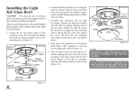
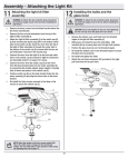
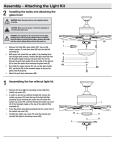
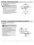
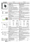
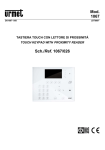
Blade Balancing
All blades are grouped by weight. Because natural woods vary in density, the fan may wobble
even though the blades are weight matched. The
following procedure should correct most fan
wobble. Check after each step.
1. Check that all blades are securely mounted
to the blade brackets with the locking mechanisms engaged.
2. Run the fan for ten minutes. If the fan continues to wobble please contact Customer
Service and a balacing kit will be sent to you
at no charge.
TO REDUCE THE RISK OF PERSONAL INJURY,
DO NOT BEND THE BLADE HOLDERS WHILE
INSTALLING, BALANCING THE BLADES, OR
CLEANING THE FAN. DO NOT INSERT FOREIGN
OBJECTS BETWEEN ROTATING BLADES.
Attaching the Light
Fixture/Glass Shades
CAUTION - To reduce the risk of electric
shock, disconnect the electrical supply circuit
to the fan before installing the light fixture.
1. Loosen the three serrated head screws on
the switch cup cover of the light kit fitter
(Figure 16).
2. Connect the wires from the light kit fitter
to the wires from the switch cup of the fan
motor assembly by connecting the molded
adaptor plugs together (blue to black, white
to white). Carefully tuck all wires and splices into the switch cup.
3. Align the three serrated head screws on the
switch cup cover of the light kit fitter with
the three key slots in the switch cup. Make
sure the notch in the switch cup cover of the
light kit fitter clears the reversing switch in
the switch cup. Position the light kit fitter
on the switch cup and turn it clockwise until it locks. Tighten the three serrated head
screws that were loosened in step 1 to secure the light kit fitter (Figure 16).
4. Remove the rubber washer, hex nut, bottom
cover and the finial from the light kit fitter
(Figure 17).
5. With power off, install the two fluorescent
bulbs (Max. 14W, included) by screwing
into the light bulb sockets.
6. Position the glass bowl over the threaded
nipple and pass the fan switch chain through
the side hole in the glass bowl.
7. Re-install the rubber washer and hex nut to
the threaded nipple of the light kit fitter to
secure the glass bowl properly.
8. Re-install the bottom cover and finial and
finger tighten the finial.
CAUTION - Be sure that the fan switch chain
does not make contact with the light bulbs.
Figure 16
9.
Fan Without Light Kit
1. In order to use the fan without the light kit,
remove the switch cup cover from the top
of the light kit fitter by removing the center hex nut inside the switch cup cover, and
then thread the switch cup cover off of the
threaded nipple on the top of the light kit fitter. Remove three serrated head screws,
2. Press the plastic plug (provided) into the
center hole of the switch cup cover.
3. Align the three screw holes in the switch cup
cover with the three key slots in the switch
cup. Make sure the notch in the switch cup
cover clears the reversing switch in the
switch cup (refer to figure 16 on page 9).
Figure 17
10.
4. Position the switch cup cover onto the
switch cup and install the three serrated head
screws that were removed in step 1. Turn the
switch cup cover clockwise until it locks and
tighten the three serrated head screws.
Figure 18
YOUR FAN/SWITCH CUP COVER MAY NOT LOOK
EXACTLY LIKE THE ILLUSTRATION, HOWEVER
THE INSTALLATION IS THE SAME.
Equilibrar las aspas
Todas las aspas se agrupan por peso. Como
las maderas naturales varían en densidad, el
ventilador puede oscilar aunque las aspas tengan
el mismo peso. El siguiente procedimiento
corregirá en gran medida la oscilación del
ventilador. Verifica después de cada paso.
2. Conecta los cables del soporte del kit de
3.
1. Verifica que todas las aspas estén
correctamente montadas en los soportes con
los mecanismos de cierre acoplados.
2. Enciende el ventilador durante diez
minutos. Si el ventilador continúa oscilando,
comunícate con el servicio al cliente y te
enviarán un kit de compensación de aspas,
sin costo alguno.
PARA REDUCIR EL RIESGO DE LESIONES PERSONALES,
NO DOBLAR LOS SOPORTES DE LAS ASPAS DURANTE
LA INSTALACIÓN, COMPENSACIÓN DE LAS ASPAS O
LIMPIEZA DEL VENTILADOR. NO INSERTES OBJETOS
EXTRAÑOS ENTRE LAS ASPAS EN FUNCIONAMIENTO.
Cómo instalar la lámpara/
pantallas de vidrio
PRECAUCIÓN – Para disminuir el riesgo de
descarga eléctrica, desconecta el circuito de energía
del ventilador antes de instalar la lámpara.
1. Afloja los tres tornillos dentados en la cubierta de
la caja del interruptor del soporte del kit de luces
(Figura 16).
4.
5.
6.
7.
8.
luces a los cables de la caja del interruptor
del ensamblado del motor, al conectar los
enchufes con adaptadores moldeados (azul
con negro, blanco con blanco). Coloca con
cuidado todos los cables y empalmes dentro
de la caja del interruptor.
Alinea los tres tornillos dentados de la
cubierta de la caja del interruptor del soporte
del kit de luces con las tres ranuras tipo ojo
de llave en la caja del interruptor. Asegúrate
de que la muesca en la cubierta de la caja
del interruptor del soporte del kit de luces,
permita que el interruptor de reversa en la
caja del interruptor se mueva libremente.
Coloca el soporte del kit de luces en la caja
del interruptor y hazlo girar de izquierda a
derecha hasta trabar. Ajusta los tres tornillos
dentados aflojados en el paso 1 para asegurar
el soporte del kit de luces (Figura 16).
Retira la arandela de goma, la tuerca
hexagonal, la cubierta inferior y el remate del
soporte del kit de luces (Figura 17).
Con el ventilador apagado, instala las dos
bombillas fluorescentes (máximo 14 vatios,
incluida) ajustándolas en los portabombillas.
Coloca el tazón de vidrio sobre la boquilla
enroscada y pasa la cadena del interruptor del
ventilador a través del orificio lateral en el
tazón de vidrio.
Reinstala la arandela de goma y la tuerca
hexagonal en la boquilla enroscada del
soporte del kit de luces para asegurar el tazón
de vidrio correctamente.
Reinstala la cubierta inferior y el remate,
aprieta este último con los dedos.
PRECAUCIÓN - Asegúrate de que la cadena
del interruptor no esté en contacto con las
bombillas de luz.
Ranura ojo
de llave
Azul
Negro
(3) Tornillos
dentados
Soporte
de lámpara
Interruptor
de reversa
Caja del
interruptor
Blanco
Muesca
Cubierta de
la caja del
interruptor
Figura 16
Ventilador sin kit
de luces
Caja del
interruptor
Bombillas (incluidas)
Boquilla enroscada
Arandela
de goma
Cadena del
interruptor
del ventilador
Tazón de vidrio
Tuerca hexagonal
Cubierta inferior
Remate
Figura 17
1. Con el fin de utilizar el ventilador sin el
kit de luces, retira la cubierta de la caja del
interruptor ubicado en la parte superior del
soporte del kit de luces, retirando la tuerca
hexagonal del centro dentro de la cubierta de
la caja del interruptor; y luego, desenrosca
la cubierta de la caja del interruptor de la
boquilla enroscada sobre el soporte del kit
de luces. Retira los tres tornillos dentados,
2. Empuja el tapón plástico (incluido) dentro
del orificio central de la cubierta de la caja
del interruptor.
3. Alinea los tres orificios para tornillos en la
cubierta de la caja del interruptor con las
tres ranuras tipo ojo de llave en la caja del
interruptor. Asegúrate de que la muesca en
la cubierta de la caja del interruptor permita
que el interruptor de reversa en la caja del
interruptor se mueva libremente (Ve la
Figura 16 de la página 9).
4. Coloca la cubierta de la caja del interruptor
sobre esta última e instala los tres tornillos
dentados que retiraste en el paso 1. Rota
la cubierta de la caja del interruptor de
izquierda a derecha hasta fijarla, aprieta los
tres tornillos dentados.
Ranuras ojo
de llave
Tapón plástico
(3) Tornillo
dentado
Figura 18
ES POSIBLE QUE LA CUBIERTA DE TU VENTILADOR/CAJA
DEL INTERRUPTOR NO SEA IGUAL A LA MOSTRADA EN
LA IMAGEN, SIN EMBARGO, LA INSTALACIÓN ES LA
MISMA.
10.