1
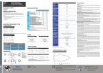
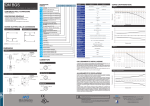
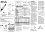
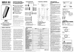
UK6 SENSORE CILINDRICO ULTRASONICO M18 CORPO CORTO Manuale d’installazione - CAT8BUK1250202 - ITA - Rev n° 2: 09/11/2012 UK • Manuale d’installazione • Manuale di sicurezza per aree pericolose • Dichiarazione di conformità CE • Etichetta con marcatura ATEX • 2 ghiere plastiche • 2 rondelle plastiche DESCRIZIONE GENERALE • Sensore ultrasonico M18 corpo corto • Modello con singola uscita digitale (PNP NO/NC) • Regolazione del range di lavoro • Completa protezione contro danneggiamenti di tipo elettrico • Indicatore LED multifunzione: stato dell’uscita, funzione di Teach-in e selezione NO/NC • Corpo plastico 8.3 3 1 Uscita connettore M12 2 LED 3 Ghiera plastica di serraggio 4 Rondella plastica 1 30.3 15.1 M12 x 1 LEGENDA: 14 (60.4) / D P 0 E AN UK6B/DP-0E** UK6C/DP-0E** Massima distanza di rilevamento 200 mm(1) 300 mm(1) 900 mm(2) Minima dist. di rilevamento (zona morta) 30 mm 100 mm 150 mm Range di regolazione (Sd) 35 - 200 mm 100 - 300 mm 150 - 900 mm Apertura fascio angolare Sensore ultrasonico M18 12 Hz Diffusione diretta 30-300 mm Isteresi 2% Diffusione diretta 100-300 mm Ripetibilità 2% Regolazione mediante teach-in esterno (*) Uscita digitale PNP- NO/NC (*) Corpo plastico assiale Compensazione in temperatura Sì Deriva termica 5% Tensione di alimentazione +15 ... 30 Vcc 5% Ondulazione residua Uscita connettore M12 Corrente di perdita ≤ 10 μA @ 30 Vcc Certificato ATEX, Cat. 3 Zona 2,22 Caduta di tensione in uscita 2 V max. @ (Il=300 mA) Corrente assorbita ≤ 35 mA Certificazione UL Frequenza di lavoro = 12 Hz ; Sn = 30-200 mm; Sd = 35-200 mm 1 Regolazione punto di lavoro Teach-in esterno 300 ms max 2 Protezione elettriche alimentazione Corto circuito autoripristinante Conforme ai requisiti della direttiva CE 2004/108/EC in accordo a EN 60947-5-2 Compatibilità elettromagnetica 2 Wh mm LEGENDA: + + Teach & N.O - N.C. - BN = marrone; BK = nero; BU = blu; WH = bianco Normal Operation In caso di carico misto, resistivo e capacitivo, la massima capacità ammessa (C) è di 0,1 μF per tensione e corrente di uscita massime. Digital Output 3 Bu - M12 P2 = 30mm per UK6A ; P2 = 100 mm per UK6B; P2 = 150 mm per UK6C; B 4 Bk Resina epossidica caricata in vetro Materiale frontale 2 Wh Uscita a connettore Peso 4 Bk 15 g Coppia di serraggio 1 Nm Temperatura di 3 Bu immagazzinamento -35...+70° C senza ghiaccio 3 Bu Disassamento parallelo UK6A UK6*/DP-0E Light On - Dark On 4 Bk 4 Bk Digita 2 Wh Digital Output 3 Bu + Light - Dark 3 Bu - Disassamento parallelo UK6C 150 +/~ Common 50 2 Wh Digital Output NO Digital Output NC Target 100x100 mm 0 -50 -100 3 Bu0 + 1 Bn + Double Digital Output 2 Wh 4 Bk NO NC 50 100 150 200 Distanza (mm) 250 300 350 -/~ 3 Bu Distanza (mm) - ATTENZIONE Questo prodotto NON è un componente di sicurezza e NON deve essere usato in applicazioni di salvaguardia della sicurezza delle persone. 2 Wh + società di 1 Bn NC 4 Bk + NO Double Digital O 3 Bu Distanza (mm) M.D. Micro Detectors S.p.A. con Unico Socio Strada S. Caterina, 235 - 41122 Modena Italy Tel. +39 059 420411 Fax +39 059 253973 www.microdetectors.com [email protected] Italian Sensors Technology Dichiarazione di conformità M.D. Micro Detectors S.p.A. con Unico Socio dichiara sotto la propria responsabilità che questi prodotti sono conformi ai contenuti della direttiva CEE: 2004/108/CE e ai successivi emendamenti. 1 Bn 1 Bn -150 -/~ +/~ 100 II 3G Ex nA IIC T5 II 3D Ex tD A22 IP67 T 90°C Numero di certificato: 1112022X 1 Bn + Disassamento parallelo UK6B 1 Bn Modello UK6*/**-**AN Italian Sensors Technology 2 Wh - 1 Bn + Grilamid 4 Bk 5 Gr 1 Bn PBT CURVE CARATTERISTICHE 1 Bn 2 Wh + Materiale contenitore Disassamento laterale (mm) mm IP67 (EN60529)(3) 1 Bn 4 (1) Target metallico 100x100 mm (2) Target metallico 200x200 mm (3) Protezione garantita solo con il cavo correttamente montato CONNETTORI P2 3 Inversioni polarità, sovratensioni impulsive Protezioni elettriche di uscita Uscita singola digitale PNP NO/NC 300 mA, 100 mA (UK6*/**-**AN e UK6*/**-**UL) 300 mA Corrente di uscita Ritardo alla disponibilità SCHEMI ELETTRICI DELLE CONNESSIONI 4 Bk P2 - 20..60° C - 20..70° C Range di temperatura P1 e P2 P1 è il punto che individua la massima distanza di rilevamento desiderata. P2 è il punto che individua la minima distanza di rilevamento che è fissa e corrisponde alla distanza Minima di rilevamento, riportata nella tabella delle Specifiche Tecniche. REGOLAZIONE DELLA POSIZIONE DEL PUNTO P1 Porre l’oggetto da rilevare alla distanza desiderata P1 e collegare il filo bianco al filo marrone per un tempo compreso tra 1 secondo e 15 secondi. Il LED passerà dallo stato ON allo stato OFF e in quel momento il sensore avrà acquisito la posizione del punto P1. Quando il filo bianco viene scollegato, il LED lampeggerà per 3 volte. Durante il funzionamento normale del sensore, tenere il filo bianco collegato al filo blu. CONFIGURAZIONE DELLO STATO NO E DELLO STATO NC Tutti i sensori a ultrasuoni sono configurati presso la Produzione di M.D. Micro Detetcors nello stato NO (Normalmente Aperto). E’ possibile cambiare lo stato logico dell’uscita collegando il filo bianco al filo marrone per un tempo di 15 secondi fintanto che il LED non inizierà a lampeggiare a frequenza elevata. Quando si scollega il filo bianco dal filo marrone lo stato dell’uscita è stato cambiato. Durante il funzionamento normale del sensore, tenere il filo bianco collegato al filo blu. CONDIZIONI DI INSTALLAZIONE L’installazione del sensore deve essere fatta utilizzando sempre le ghiere plastiche e le rosette fornite in dotazione con il sensore (vedere Contenuto della confezione). Nel caso in cui sia necessario installare il sensore all’interno di blocchi metallici con fori passanti o filettati od utilizzando ghiere metalliche, sia il blocco metallico sia le ghiere metalliche devono essere messe a massa e devono distare almeno 5 mm dal frontale del sensore o comunque garantire i primi 5 mm di corpo filettato liberi. CONSERVAZIONE DEGLI STATI Il sensore mantiene in memoria l’ultima regolazione effettuata, pertanto togliendo l’alimentazione e ripristinandola il sensore lavora secondol’ultimo valore di P1 selezionato. AVVERTENZE Assicurarsi che la tensione di alimentazione sia correttamente stabilizzata con una ondulazione residua (ripple) compresa all’interno dei dati di catalogo. Nel caso che il rumore indotto dalle linee di potenza risulti superiore a quello previsto dalla normativa CE (immunità ai disturbi), separare i cavi del sensore dalle linee di potenza e di alta tensione e inserire il cavo in una canalina metallica connessa a terra. E’ consigliabile inoltre, collegare il sensore direttamente alla sorgente di alimentazione e non a valle di altri dispositivi. Per estendere i cavi di alimentazione e uscita utilizzare un cavo avente conduttori di sezione minima di 1 mm2. Il limite di estensione in lunghezza è 100 m (riferiti a tensione minima e corrente al carico di 100mA).Come d’uso in ambiente industriale, si consiglia l’utilizzo di schermature dei cavi di collegamento al fine di prevenire possibili disturbi sui dispositivi provocati da campi elettromagnetici indotti. Non esporre la testa del sensore ad acqua calda >50°, vapore, acidi o solventi. Per la pulizia della faccia attiva del sensore usare un panno umido e asciugare. 6 Hz Frequenza di lavoro Diffusione diretta 150-900 mm REGOLAZIONE ± 8° ± 10° Corpo corto 1 Bn A P1 - UK6A/DP-0E1E Grado di protezione ANDAMENTO DELLO STATO DELLE USCITE P1 B (*) Regolazione della massima distanza e selezione NO/NC effettuata col Teach-in esterno M18 x 1 SW 22 O 25 45° UK 6 A B C / D P 0 E AN UL 1E 6 Modelli Disassamento laterale (mm) CONTENUTO DELLA CONFEZIONE DEGLI ARTICOLI CON CERTIFICAZIONE ATEX DIMENSIONI SPECIFICHE TECNICHE STRUTTURA DEL CODICE • Manuale d’installazione • 2 ghiere plastiche • 2 rondelle plastiche Disassamento laterale (mm) CONTENUTO DELLA CONFEZIONE 1 Bn UK6 M18 CYLINDRICAL ULTRASONIC SENSOR WITH SHORT HOUSING Installation manual - CAT8BUK1250202 - ENG - Rev n° 2 : 09/11/2012 CODE STRUCTURE Models UK6A/DP-0E1E Maximum sensing distance 200 mm Minimum sensing distance (blind zone) UK SUPPLIED MATERIAL FOR ATEX CERTIFIED PRODUCTS UK 6 A B C / D P 0 E AN UL 1E • Installation manual • Safety instructions for dangerous areas • Declaration of CE conformity • Label ATEX marked • 2 plastic nuts • 2 flexible washer GENERAL DESCRIPTION • M18 ultrasonic sensor with short housing • Model with single digital output (PNP NO/NC) • Operating distance adjustment • Complete protection against electrical damages • Multifunction LED indicator: output state, Teach-in function and NO/NC configuration • Plastic housing DIMENSIONS D P - 0 E AN Sensing range (Sd) ± 8° ± 10° 12 Hz 2% 150-900 mm direct diffuse Temperature range Yes Thermal drift 5% 15 ... 30 Vdc 5% Axial plastic housing Ripple M12 plug cable exit Leakage current ≤ 10 μA @ 30 Vdc ATEX certified, Cat. 3 Zone 2,22 Output voltage drop With cULus certification No-Load current Switching frequency = 12 Hz; Sn = 30-200 mm; Sd = 35-200 mm 2 V max. @ (Il=300 mA) ≤ 35 mA Output current 300 mA, 100 mA (UK6*/**-**AN and UK6*/**-**UL) 300 mA External Teach-in 2 Time delay before availability 14 A + + 2 Wh 4 Bk Normal Operation Digital Output M12 P2 = 30 mm for UK6A; P2 = 100 mm for UK6B; P2 = 150 mm for UK6C In case of combined load, resistive and capacitive, the maximum admissible capacity (C) is 0,1 μF for maximum output voltage and current. B 4 Bk 5 Gr Short circuit, overvoltage pulses Conforming to the EC Directive 2004/108/EC requirements according to EN 60947-5-2 1 Bn + Protection degree 1 Bn PBT Housing material 2 Wh Epoxy-Glass resin Exit plug + Light On - Dark On 4 Bk Grillamid 4 Bk 1 Bn + IP67 (EN60529)(3) 2 Wh 4 Bk Digital O 2 Wh Digital Output 15 g Weight Tightening torque 3 Bu - 3 Bu - 1 Bn + 1 Nm - + Light On - Dark On 3 Bu -35...+70° C without freezing Storage temperature (1) Metallic target 100x100 mm (2) Front metallic target 200x200 mm (3) Front protection guarantee only with plug cable well mounted UK6*/DP-0E 1 Bn 2 Wh EMC Front end material PLUGS mm mm BN = brown; BK = black; BU = blue; WH = white Teach & N.O - N.C. - Polarity reversal, overvoltage pulses Digital output electrical protections 4 3 300 ms max Supply electrical protections KEY: 1 Bn - 20..60° C - 20..70° C Temperature compensation Operating voltage +/~ 1 Bn CHARACTERISTIC CURVES +/~ Parallel displacement UK6A Common Parallel displacement UK6B 2 Wh 150 Digital Output NO 3 Bu -/~ Parallel displacement UK6C 2 Wh Target 100x100 mm 0 3 Bu -/~ -50 -100 NC NO 4 Bk 50 Digital Output NC 1 Bn Double Digital Output 2 Wh 100 Parallel Displacement (mm) 15.1 M12 x 1 30.3 6 Hz Repeat accuracy 3 Bu P2 150 - 900 mm 100-300 mm direct diffuse 1 (60.4) P2 100 - 300 mm 2% PNP NO/NC models with single digital output 1 35 - 200 mm Hysteresis PNP- NO/NC digital output (*) P1 and P2 P1: coincides with the maximum working distance requested. P2: coincides with the minimum working distance that is fixed. It is listed in the table of Technical Specifications. TEACH-IN OF P1 POSITION Place the target at the right distance P1, then connect the white wire to the brown wire for a time included between 1 second and 15 seconds.The LED turns ON from OFF state, and the sensor will acquire the position P1. When the white wire is unconnected the LED will blink three times. During the normal sensor functioning keep the white wire connected to the blue wire. CONFIGURATION OF NO AND NC STATES All the sensors are delivered from factory in NO (Normally Open) state. It is possible to change the logical output state connecting the white wire to the brown wire for more then 15 seconds until the LED starts to blink fast. When the white wire is connected to the brown wire, the output state will change. During the normal sensor functioning keep the white wire connected to the blue wire. INSTALLATION CONDITION The fixation of the sensor has to be done using plastic nut and flexible washer supplied with ultrasonic sensor (see Supplied Material). If the sensor is fixed directly into metal block through hole or threaded, it is necessary to use always flexible washer and plastic nut. Anyway both nuts and metal block have to be minimum 5 mm from the edge of the active face and it is necessary that the first 5 mm of the threaded housing are not screwed. Both metal blocks and nuts have to be connected to ground. STATES PRESERVATION The sensor preserves the last working range selected: removing the voltage supply and restoring it, the sensor works in according to last value of P1 selected. ATTENTION Make sure that the supply voltage is correctly set with a ripple corresponding to the values indicated on the catalogue. In case the noise produced by the power lines exceed the values foreseen by the EC norm (interference immunity), separate the sensor cables from both the power and high tension lines and insert it in a grounding metal raceway. Moreover it is advisable to connect the sensor directly to the supply source and not to other devices. To extend the supply and output cables, it is necessary to use a cable having conductors with a minimum size of 1 mm2. The maximum length of extension is 100 m (this value is referred to a minimum tension and power supply at the load of 100 mA). In industrial environments, we recommend to use shielded cables in order to prevent possible disturbances on the devices caused by electromagnetic fields induced. Do not expose sensor head to hot water > 50° C, water steam, acids or solvents. Clean the active face of the sensor with a wet cloth and the dry it. (2) 150 mm 30-300 mm direct diffuse Sensitivity adjustment by external teach-in 900 mm (1) 100 mm Switching frequency Short housing 300 mm UK6C/DP-0E** 30 mm Beam angle ELECTRICAL DIAGRAMS OF THE CONNECTIONS M18 x 1 SW 22 O 25 / UK6B/DP-0E** (1) Adjustment set point 3 OUTPUT CURVES P1 B M18 ultrasonic sensor 8.3 KEY 1 M12 plug cable exit 2 LED 3 Plastic tightening nut 4 Flexible washer P1 6 (*) Max. sensitivity adjustment and NO/NC selection available by external Teach-in 45° ADJUSTMENT TECHNICAL SPECIFICATIONS 4 Bk NO NC 3 Bu - Parallel Displacement (mm) • Installation manual • 2 plastic nuts • 2 flexible washer Parallel Displacement (mm) SUPPLIED MATERIAL 4 Bk Double Digital Out 3 Bu -150 0 Model UK6*/**-**AN 1 Bn Italian Sensors Technology C 2 Wh II 3G Ex nA IIC +T5 II 3D Ex tD A22 IP67 T 90°C N.O - N.C. + Teach Number of&certificate: 1112022X - Normal Operation 50 100 150 200 Distance (mm) 250 300 350 2 Wh Distance (mm) WARNING These products are NOT safety sensors and are NOT suitable for use in personnel safety application 1 Bn 1 Bn Declaration of conformity + M.D. Micro Detectors S.p.A. con Unico Socio declare under our sole responsibility that these products are in conformity with the following EEC directive: 2004/108/ EC and subsequent amendments 2 Wh Distance (mm) Italian Sensors Technology a company of + M.D. Micro Detectors S.p.A. con Unico Socio Strada S. Caterina, 235 - 41122 Modena Italy 1 Bn Tel. +39 059 420411 Fax +39 059 253973 www.microdetectors.com [email protected] 4 Bk Digital Output