1
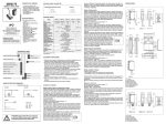
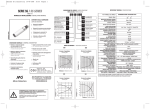
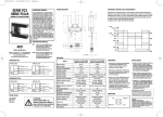
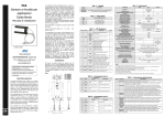
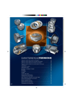
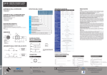
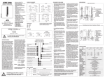
Uscita NPN
1 Bn
carico
100mA
+10-30
VDC
Uscita cavo, 4x0,34mm2,
Ø4,7mm, PVC, 2m
Uscita connettore M12
Pulsante di teach-in
Ghiera per fissaggio fibra (inclusa)
4 Bk
+ impulso buio
2 Wh
n.c impulso luce
- teach
OV
3 Bu
• CONTENUTO DELLA CONFEZIONE
Manuale di Installazione
N°1 amplificatore SSF per fibre ottiche • N°2 ghiere M18 (plastiche per SSF/**-0*, metalliche SSF/**-1* )
• SPECIFICHE
Uscita PNP
1 Bn
TIPO
+10-30
VDC
+ impulso buio
2 Wh
carico
100mA
4 Bk
n.c impulso luce
- teach
OV
3 Bu
CODICE COLORI
www.microdetectors.com
[email protected]
1/Bn : Brown/Marrone
2/Wh : White/Bianco
3/Blu : Blue/Blu
4/Blk : Black/Nero
N.B In caso di carico misto resistivo e capacitivo la
massima capacità ammessa è di 0,1 µF per tensioni
e correnti di uscita massime.
Amplificatore M18 per fibre ottiche plastiche o in vetro
Regolazione digitale della sensibilità mediante pulsante di teach-in o cavo remoto
Led multifuzione con indicazione del livello del segnale
Distanza di rilevazione:
• Tasteggio diretto: 50 mm (con CF/CB1)
• Barriera: 120 mm (con CF/RB6)
Emissione : rossa (660 nm)
Materiale contenitore: PBT (corpo plastico), ottone nichelato (corpo metallico)
Uscita: NPN o PNP, 100 mA, con protezione al cortocircuito.
• DESCRIZIONE DEL CODICE
SSF / 0 N - 0 A
SSF
Stato uscita
LOn / DOn selezionabile
A
Attacco di uscita
Uscita cavo
assiale 4 poli
E
Uscita
connettore M12
Contenitore
0
0
Contenitore plastico
1
Contenitore metallico
Tipo uscita
N
Uscita NPN
P
Uscita PNP
Cortocircuito ( autoripristinante )
-25 °C / +70 °C ( senza condensa)
10% Sr
3000 lux (lampada incandescenza) , 10000 lux (luce solare)
IP67 (EN60529)
• TABELLA DELLE FIBRE OTTICHE
• DESCRIZIONE GENERALE
Serie
sensore M18 a
fibra ottica
≤10 %
+15/-5%
5%
10 – 30 Vdc
10 %
20 mA
10 µA
100 mA
NPN o PNP , LOn / DOn selezionabile
1.8 V max a 100 mA
150 ms
800 Hz
Inversione di polarità , sovratensioni impulsive
ATTENZIONE
(1)
Questo prodotto
non è un sensore di
sicurezza e non può
essere utilizzato come
protezione di accesso
a zone pericolose
MODELLO(1)
TIPO
CF/CA2-**
Riflessione diretta
15mm
0,5mm
NO
0,5 – 1m
M4
Distanza di Rilevazione øFIBRA (nucleo) TAGLIABILE
LUNGHEZZA Terminazione (mm)
CF/CA4-**
Riflessione diretta
15 mm
0,5 mm
NO
0,5 – 1m
M4 con sleeve
CF/RA4-**
Barriera
30mm
0,5mm
NO
0,5 – 1m
M4 con sleeve
CF/RA7-**
Barriera
30mm
0,5mm
NO
0,5 – 1m
M4 con sleeve
CF/CB1-**
Riflessione diretta
50mm
1mm
SI
1-2 m
M6
CF/RB4-**
Riflessione diretta
50mm
1mm
SI
1-2 m
M6 con sleeve
M4 con sleeve
CF/CB3-**
Barriera
120 mm
1mm
SI
1-2 m
CF/RB6-**
Barriera
120 mm
1mm
SI
1-2 m
M4
CF/RB9-**
Barriera
1200 mm
1mm
SI
1-2 m
ø6 con lenti
CF/RBA-**
Barriera
1200 mm
1mm
SI
1-2 m
M7 con lenti
CF/CC1-20
Riflessione diretta
15mm
1mm
NO
2m
M6
CF/RC6-20
Barriera
100mm
1mm
NO
2m
M4
CF/RC9-20
Barriera
1000mm
1mm
NO
2m
ø6 con lenti
CF/RCA-20
Barriera
1000mm
1mm
NO
2m
M7 con lenti
CV/CB1-**
Riflessione diretta
50 mm
1mm
NO
1-2 m
M4
CV/CB3-**
Riflessione diretta
50mm
1mm
NO
1-2 m
M4 con sleeve
CV/RB4-**
Barriera
90 mm
1mm
NO
1-2 m
M4 con sleeve
CV/RB6-**
Barriera
90 mm
1mm
NO
1-2 m
M4
Sono possibili due tipi di regolazione , regolazione standard
e regolazione fine della sensibilità del dispositivo. La
regolazione fine è ottimale per ottenere la massima
sensibilità nella rilevazione di oggetti piccoli e
semitrasparenti; nel caso di oggetti opachi e di
dimensioni maggiori o qualora lo sfondo non influenzi la
lettura è conveniente utilizzare la regolazione standard ,
garantendo al sistema la possibilità di lavorare anche in
ambienti gravosi.
Tasteggio diretto.
Dopo avere installato l’unità e le terminazioni delle fibre
posizionare l’oggetto da rilevare alla distanza di lettura
desiderata , verificando che l’asse ottico sia perpendicolare
alla superficie dell’oggetto. Assumendo le peggiori
condizioni ( oggetto statisticamente più piccolo e oggetto
o parte di esso più scura rispetto allo sfondo) posizionare
l’oggetto nel punto più distante che può assumere rispetto
al sensore. Premere il pulsante di teach o collegare il pin
2 (cavo bianco) a massa per 2…5 sec. fino a quando il
LED di segnalazione giallo non si riaccende in modo
stabile. La soglia viene posta al 50% del segnale rilevato e
si ha una regolazione standard della sensibilità del
dispositivo. Togliere l’oggetto e verificare lo spegnimento
del led giallo. Nel caso il led giallo rimanga acceso
occorre una regolazione fine della sensibilità .
Per effettuare la regolazione fine collegare il pin 2 (cavo
bianco) a massa o premere il pulsante di Teach-in per t >
8sec. fino a quando il LED di segnalazione giallo non
inizia a lampeggiare, la soglia viene posta al di sotto del
segnale rilevato di una quantità pari all’isteresi. Togliere
l’oggetto e verificare lo spegnimento del LED giallo.
Emettitore / Ricevitore.
Dopo avere installato l’amplificatore posizionare le
terminazioni in opposizione una rispetto l’altra all’interno
della distanza di rilevazione. Regolare accuratamente la
posizione reciproca di ricevitore ed emettitore fino
all’accensione del led giallo , fissando provvisoriamente le
terminazioni al centro di questa zona. Per ottenere un
allineamento ottimale seguire la procedura seguente.
Premere il pulsante di teach o collegare il pin 2 (cavo
bianco) a massa per t > 8sec sec. fino a quando il LED di
segnalazione giallo non inizia a lampeggiare. Allineare
reciprocamente il ricevitore rispetto all’emettitore
cercando di ottenere uno stato del led acceso stabile o
eventualmente una diminuzione della frequenza di
lampeggio. Ripetere l’operazione fino a quando non sia
più possibile variare la frequenza del lampeggio del LED
giallo. In tali condizioni si è effettuata una regolazione
fine della sensibilità del dispositivo. Tale regolazione
risulta ottimale per la rilevazione precisa di piccoli oggetti
o per la rilevazione di oggetti semitrasparenti.
Per le applicazioni in cui si devono intercettare oggetti non
trasparenti e di dimensioni superiori al diametro della
fibra ( dopo avere effettuato le operazioni
precedentemente indicate) , si consiglia di usare la
regolazione standard , in questo modo si avrà il massimo
margine di immunità nei confronti della polvere e dello
sporco che si può depositare sulle ottiche.
Per ottenere una regolazione standard premere il pulsante di
teach o collegare il pin 2 (cavo bianco) a massa per
2…5 sec. fino a quando il LED di segnalazione giallo non
si riaccende in modo stabile.
Regolazione con configurazione impulso buio
Se è necessario utilizzare l’ingresso di Teach con una
configurazione IMPULSO BUIO (DARK ON) si deve
aggiungere un resistore di 2.2 KΩ per evitare il corto
circuito con l’alimentazione quando il Teach è attivo
1 10...30 Vdc
(1) Gli ultimi due bit del codice indicano la lunghezza dalla fibra
(in dm) –(2) Lunghezza standard. Lunghezze speciali disponibili su richiesta.
2.2 K Ω
Strada S.Caterina, 235 - 41100 Modena Italy
Tel. +39 059 420411 Fax +39 059 253973
Fotocellula M18 a fibbra ottica
Corsa differenziale
Tolleranza
Ripetibilità
Tensione di alimentazione
Ondulazione residua
Corrente assorbita
Corrente di perdita
Corrente di uscita
Tipo di uscita
Caduta di tensione in uscita
Ritardo alla disponibilità
Frequenza di commutazione
Protezioni elettriche
alimentazione
Protezioni elettriche uscita
Limiti di temperatura
Deriva termica
Interferenza alla luce esterna
Grado di protezione
• FISSAGGIO FIBRE OTTICHE
• MONTAGGIO
1 Svitare non completamente la ghiera blocca fibra. Inserire
completamente la fibra ottica prestando attenzione che
tocchi il fondo della sede (vincendo la leggera resistenza
provocata dalla guarnizione di tenuta) e serrare
saldamente la ghiera di fissaggio.
2 Non applicare alle fibre una forza maggiore di 3Kg. Non
tirare le fibre e rispettare sempre il raggio di curvatura
minimo indicato (5 mm per fibre Ø 0,5 , 10mm per fibre Ø
1 e 30 mm per fibre in vetro ).
3 Fissare le fibre con passacavi di nylon in modo da non
esercitare pressioni deformanti sulla fibra che ne
potrebbero compromettere il funzionamento.
1 Prestare attenzione al taglio che deve essere eseguito in
maniera corretta utilizzando il cutter AF/C fornito a
corredo.
2 Non riutilizzare un foro già utilizzato in quanto
aumentano le possibilità di taglio irregolare con possibili
riduzioni della sensibilità.
il sensore all'interno della distanza nominale di lavoro.
Per verificare se il sensore è in grado di regolare la
sensibilità correttamente , è consigliabile effettuare
sempre una regolazione fine ed accertarsi dello stato
lampeggiante del led al termine della procedura. Se il led
rimane fisso , il sensore lavora ad una distanza troppo
elevata in rapporto all’oggetto da rilevare o il sensore non
è correttamente allineato. Se è sufficiente rilevare la
presenza di oggetti e non si è influenzati da sfondi o altri
oggetti dietro quello da rilavare, è possibile utilizzare il
sensore fino alla distanza indicata nelle curve e nel caso
ripetere la taratura effettuando una regolazione standard.
Le curve indicano il rapporto tra la posizione in cui il
sensore viene posto per effettuare la regolazione di
sensibilità e la posizione in cui il sensore si attiva con un
margine >=2.
Regolazione con CF/CB1
Don/Doff (cm)
Manuale di installazione
• REGOLAZIONE DIGITALE
DELLA SENSIBILITA’
16
14
Doff carta bianca
12
10
Don carta bianca
8
Doff carta nera
6
4
Don carta nera
2
0
0
1
2
3
4
5
6
7
8
9
Regolazione con CF/RB6
36
32
Doff
28
24
Don
20
16
12
8
4
0
0
2
4
6
8
10
12
14
16
18
20
22
24
Note sulla regolazione.
Oltre la distanza nominale del sensore la regolazione fine
non ha più influenza sulla distanza di intervento sia nel
caso di utilizzo a barriera che di utilizzo a tasteggio
diretto. Come si può vedere dalle curve seguenti l’isteresi
aumenta all'aumentare della distanza di regolazione. Se
occorre avere una regolazione fine è necessario utilizzare
28
• CONNESSIONI
1 Assicurarsi che la tensione di alimentazione sia
correttamente stabilizzata con una ondulazione residua
(ripple) compresa all’interno dei dati di catalogo.
2 Utilizzando uno stabilizzatore di tensione di tipo
“switching” assicurasi che il terminale di massa sia
connesso a terra come il comune del sensore.
3 Nel caso che il rumore indotto dalle linee di potenza
risulti superiore a quello previsto dalla normativa CE
(immunità ai dis-turbi), separare i cavi del sensore dalle
linee di potenza e di alta tensione e inserire il cavo in
una canalina metallica connessa a massa. E’ consigliabile
inoltre, collegare il sensore direttamente alla sorgente di
alimentazione e non a valle di altri dispositivi.
4 Per estendere i cavi di alimentazione e uscita utilizzare un
cavo avente conduttori di sezione minima di 1 mm2. Il
limite dell’estensione in lunghezza è 100m (riferiti a
tensione minima e corrente al carico di 100mA).
5 Lo stato del sensore diventa valido solo dopo 150ms dalla
for-nitura di alimentazione (ritardo alla disponibilità). In
questo periodo le uscite saranno OFF. Non utilizzare il
segnale di uscita durante questo intervallo di tempo.
• CONNETTORE
(Uscita)
3 OV
26
Distanza regolazione
alimentazione (-)
4 Uscita
Luce
2 Impulso
Impulso Buio
10
Distanza regolazione
Don/Doff (cm)
SERIE SSF
• DISEGNI MECCANICI
4
3
1
2
Alimentazione (+)
Impulso luce/buio
regolazione remota
Two types of sensitivity adjustment are available, standard
adjustment and fine adjustment. Fine adjustment is ideal
for achieving the greatest sensitivity for the detection of
small and semi-transparent objects; if the target objects
are opaque or of larger dimensions, or if the background
does not affect the reading, standard adjustment should
be used as it guarantees that the system can operate in
harsh environments.
NPN Output
1 Bn
load
100mA
+10-30
VDC
Cable exit, 4x0,34mm2,
Ø4,7mm, PVC, 2m
M12 plug cable exit
Teach-in button
Locking ring nut (supplied)
4 Bk
+ dark on
2 Wh
n.c light on
- teach
OV
3 Bu
• SUPPLIED MATERIAL
Installation Manual
N°1 photoelectric sensor SSF for optical fibres • N°2 M18 ring nut (plastic for SSF/**-0*, metal for SSF/**-1*)
• SPECIFICATIONS
PNP Output
1 Bn
MODEL
+10-30
VDC
+ dark on
2 Wh
load
100mA
4 Bk
n.c light on
- teach
OV
3 Bu
WIRING COLORS
www.microdetectors.com
[email protected]
1/Bn : Brown
2/Wh : White
3/Blu : Blue
4/Blk : Black
NOTE. In case of combined load , resistive and
capacitive, the maximum admissible capacity
is 0,1 µF for maximun output voltage and current
• OTICAL FIBRES TABLES
• GENERAL DESCRIPTION
M18 amplifier for plastic or glass optical fibres
Digital sensitivity adjustment by teach-in button or remote cable
Multifunction LED with signal level indication
Sensing distance:
• Diffused reflection: 50 mm (with CF/CB1)
• Through beam: 120 mm (with CF/RB6)
Emission : red (660 nm)
Housing Material: PBT (plastic housing), nickel-plated brass (metal housing)
Output : NPN or PNP, 100 mA, with short circuit protections.
• CODE DESCRIPTION
SSF / 0 N - 0 A
Series
M18 photoelectric
sensors for optical
fibre
SSF
A
Cable exit
Axial cable
exit
E
M12 plug
cable exit
WARNING
These products
Housing
0
0
Plastic housing
1
Metal housing
and are NOT suitable
for use in personal
Output type
N
NPN output
P
PNP output
MODEL(1)
TYPE
FREE-CUT
LENGHT
Head shape (mm)
CF/CA2-**
Diffuse reflection
15mm
0,5mm
NO
0,5 – 1m
M4
Sensing distance øFIBRE (core)
CF/CA4-**
Diffuse reflection
15 mm
0,5 mm
NO
0,5 – 1m
M4 with sleeve
CF/RA4-**
Trough beam
30mm
0,5mm
NO
0,5 – 1m
M4 with sleeve
CF/RA7-**
Trough beam
30mm
0,5mm
NO
0,5 – 1m
M4 with sleeve
CF/CB1-**
Diffuse reflection
50 mm
1mm
YES
1-2 m
M6
CF/RB4-**
Diffuse reflection
50mm
1mm
YES
1-2 m
M6 with sleeve
M4 with sleeve
CF/CB3-**
Trough beam
120 mm
1mm
YES
1-2 m
CF/RB6-**
Trough beam
120 mm
1mm
YES
1-2 m
M4
CF/RB9-**
Trough beam
1200 mm
1mm
YES
1-2 m
ø6 with lens
CF/RBA-**
Trough beam
1200 mm
1mm
YES
1-2 m
M7 with lens
CF/CC1-20
Diffuse reflection
15mm
1mm
NO
2m
M6
CF/RC6-20
Trough beam
100mm
1mm
NO
2m
M4
CF/RC9-20
Trough beam
1000mm
1mm
NO
2m
ø6 with lens
M7 with lens
CF/RCA-20
Trough beam
1000mm
1mm
NO
2m
CV/CB1-**
Diffuse reflection
50 mm
1mm
NO
1-2 m
M4
CV/CB3-**
Diffuse reflection
50mm
1mm
NO
1-2 m
M4 with sleeve
CV/RB4-**
Trough beam
90 mm
1mm
NO
1-2 m
M4 with sleeve
CV/RB6-**
Trough beam
90 mm
1mm
NO
1-2 m
M4
(1)
are NOT safety sensors
Output state
LOn/DOn selectable
≤10 %
+15/-5%
5%
10 – 30 Vdc
10 %
20 mA
10 µA
100 mA
NPN or PNP , Lon / Don selectable
1.8 V max at 100 mA
150 ms
800 Hz
Polarity reversal , transient
Short circuit ( autoreset )
-25 °C / +70 °C ( without freeze)
10% Sr
3000 lux (incandescent lamp) , 10000 lux (sunlight)
IP67 (EN60529)
safety application
Diffused reflection.
After having installed the unit and the fibre terminations,
position the target object at the required sensing distance
, checking that the optical axis is perpendicular to the
surface of the object. Assuming the worst possible
conditions (object statistically smaller and object or part
of object darker than the background), position the object
at the furthest possible point from the sensor. Press the
teach button or connect pin 2 (white cable) to earth for
2-5 secs. until the yellow signal LED switches back on
constantly. The threshold is set at 50% of the detected
signal, thus giving the device a standard sensitivity
adjustment. Remove the object and check that the yellow
LED has switched off. If the yellow LED remains switched
on, fine sensitivity adjustment is required.
To carry out the fine adjustment connect pin 2 (white cable)
to earth or press the Teach-in button for t > 8 secs. until
the yellow signal LED starts flashing. The threshold is set
below the detected signal of the hysteresis amplitude.
Remove the object and check that the yellow LED has
switched off.
Emitter / Receiver.
After having installed the amplifier, position the terminations
diametrically opposed within the sensing distance.
Carefully adjust the relative positions of the receiver and
the emitter until the yellow LED switches on, provisionally
fixing the terminations in the centre of this area. To
achieve the best alignment, use the following procedure.
Press the teach button or collect pin 2 (white cable) to
earth for t > 8 secs. until the yellow signal LED starts
flashing. Align reciprocally the receiver and the emitter
until the LED is constantly switched on or at least until
the frequency of the flashes decreases. Repeat the
operation until it is no longer possible to vary the
frequency at which the yellow LED flashes. In this way a
fine sensitivity adjustment of the device has been carried
out. This adjustment is ideal for the accurate detection of
small objects or for the detection of semi-transparent
objects.
For applications in which the target objects are not
transparent or are larger than the diameter of the fibre (
after the operation before indicated) , the standard
adjustment is recommended. This gives the highest
possible margin of immunity to the dust or dirt which can
deposit on the optical elements.
To carry out a standard adjustment press the teach button or
connect pin 2 (white cable) to earth for 2-5 secs. until
the yellow signal LED switches back on constantly.
Teach with Dark ON configuration
Should it be necessary to use the teach input with a DARK ON
configuration 2.2 KΩ resistor must be added to avoid
short circuits in the power supply when the teach mode is
active.
1 10...30 Vdc
Sensitivity adjustment with CF/CB1
16
14
Doff white paper
12
10
Don white paper
8
Doff black paper
6
4
Don black paper
2
0
0
1
2
3
4
5
6
7
The last two bit of the code show the fiber lenght (in dm) –(2) Standard
length. Special lengths are available on request.
4 out
• OPTICAL FIBRE MOUNTING
• INSTALLATION
2 LOn/DOn
1 Unscrew not completely but work loose the locking ring
nut. Then connect the optical fibres and make sure to get
the bottom of the slot (sealing will be causing a light
resistance). Tighten the locking nut firmly.
2 Do not apply undue force to the fibres. They endure a
force of 3Kg. Do not pull the fibres and respect the
indicated minimum bending radius (5mm for Ø 0,5 , 10
mm for Ø 1 and 30 mm for glass optical fibres) .
3 Fibres can be fixed with leads of nylon, cable clamps as to
not exert any deforming pressure on the fibres which
could affect detection.
1 Take care when effecting the cut which shall be done
correctly as to secure a perfect optical connection. Cut the
fibres unit with the cutter AF/C supplied as an accessory.
2 Do not use each hole more than once because the cut may
be rough, resulting in shortening the detecting distance.
3 OV
Adjustment notes.
Beyond the nominal distance of the sensor, the fine
adjustment has no effect on the operating distance. As
shown from the curves, the hyteresis increases with a
correspondent increase in the teach distance. If a fine
adjustment is required, the sensor must be used within
the nominal sensing distance. To check if the sensor is
8
9
10
Teach distance (cm)
Sensivity adjustament with CF/RB6
36
32
Doff
28
24
Don
20
16
12
8
4
0
0
2
4
6
8
10
12
14
16
18
20
22
24
26
28
Teach distance (cm)
• CONNECTIONS
1 Make sure that the operating voltage is correctly
stabilized with a maximum ripple being within the
specified figure as stated in the catalogue.
2. When using a “switching” regulator for the power source,
be sure to earth both the frame round terminal and the
sensor.
3 In the event that the noise induced by the power lines is
greater than that specified by the EC regulation
(interference immunity), detach the sensor cables from
the power and high voltage lines and insert the cable in
an earthed metal conduit. Furthermore, it is advisable to
connect the sensor directly to the supply source and not
downstream of other devices.
4 To extend the supply and output cables, a cable with a
minimum cross-section of 1mm2 must be used. The length
of such an extension is limit to a maximum of 100m (with
respect to a minimum voltage and load current of 100mA).
5 The sensor will become active 150ms after supply voltage
is applied. During this time, the outputs will be OFF.
• CONNECTOR
2.2 K Ω
Strada S.Caterina, 235 - 41100 Modena Italy
Tel. +39 059 420411 Fax +39 059 253973
M18 photoelectric sensor for optical fibre
Differential travel
Tolerance
Repeat accurancy
Operating voltage
Ripple
No load current
Leakage current
Load current
Output type
Output voltage drop
Time delay before availability
Switching frequency
Supply electrical protection
Output electrical protection
Temperature range
Temperature drift
Interference from external light
Protection degree
capable of adjusting the sensitivity correctly, it is always
advisable to carry out a fine adjustment and to make
certain that the LED is flashing at the end of the
procedure. If the LED remains constant, either the sensor
operates at too high distance in relation to the target
object or the sensor is not correctly aligned. If it is
sufficient only to detect the presence of objects and this
is not affected by backgrounds or other objects behind
those to be detected, the sensor can be used till the
distance indicated in the curves is reached. If necessary,
repeat the setting by carrying out a brief teach. The
curves represent the relationship between the position in
which the sensor is placed to carry out the sensitivity
adjustment and the position in which the sensor is
activated with an margin >=2.
Don/Doff (cm)
Installation Manual
• DIGITAL SENSITIVITY
ADJUSTMENT
Don/Doff (cm)
SERIE SSF
• MECHANICAL DRAWINGS
(OUT)
Supply (+)
Supply (-)
4
3
1
2
Light/Dark/Teach