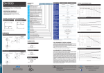
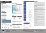
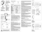
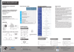
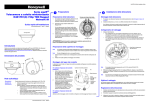
1
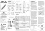
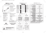
QM
DESCRIZIONE DEL
CODICE
SENSORE FOTOELETTRICO
CUBICO MINIATURIZZATO
QM
R
I
B
7
Manuale d’installazione - CAT8BQM1467001 - ITA - Creato: 22/04/2014
CONTENUTO DELLA CONFEZIONE
• Manuale d’istallazione
DESCRIZIONE GENERALE
• Fotocellule rettangolari miniaturizzate ad alte prestazioni
• Emissione infrarossa e rossa ad alta intensità
• Sensibilità regolabile mediante trimmer
• Stato dell’uscita LO/DO selezionabile
• Frequenza di commutazione fino a 2Khz
1
4
SCHEMI ELETTRICI
DELLE CONNESSIONI
3
3
Uscita PNP
+
+
Light On
-
Dark On
22Wh
Wh
-
++
Light
On& N.O - N.C.
Teach
--
Dark On
Normal Operation
+
2 Wh
Digital Output
2 Wh
4 Bk +
Light On
3 Bu
3 Bu
Light On
-
+
-
Dark On
3 Bu
--
4 Bk
Digital Output
2 Wh
Digital Output
Digital Output
3 Bu
3 Bu
4 Bk
+ 1 Bn
1 Bn
-
+
Dark On
-
-
CONNETTORI
QM**-0*-0* (M8 4 pin)
+
ble Digital Output
O
44Bk
Bk
Digital Output
1 Bn
++
2
4
Emissione
Uscita NPN
11Bn
Bn
8
9
N
NC
Bn
11Bn
2 Wh
2 Wh
4 Bk
4 Bk
5 Gr
+
Common
Double Digital Output
2
4
QM*H-0*-0* (M8 4 pin)
Uscita1 Bn BK
+/~
2 Wh
+
NC
NO
1 Bn
1 Bn
2 Wh
Wh 4
22 NC
Digital Output NO
1
3
NO DigitalNC
Output NC
4 Bk
4 Bk
Double Digital Output
3 Bu
Alimentazione
Alimentazione
(+)
Alimentazione(+)
Bu
3 Bu
33Bu
- - -/~
(-)
BU
- BN
- - BN
LEGENDA:
BN = marrone; BK = nero; BU = blu; WH = bianco
1
4 Bk
+
+/~
NO
3
Double Digital Output
3 Bu
Alimentazione(-)
- BU
-/~
ALLINEAMENTO E REGOLAZIONE
Sensore a riflessione polarizzata:
Montare il catarifrangente ed il sensore nella posizione desiderata. Ruotare il potenziometro di
regolazione della distanza in senso orario sul massimo .Per assicurarsi che il raggio luminoso
raggiunga il catarifrangente, regolare il sensore orizzontalmente e verticalmente finchè i LED
giallo e verde non risultano entrambi accesi. Ruotare il potenziometro di distanza in senso
antiorario finchè entrambi i LED non sono di nuovo costantemente accesi.
Per trasparenti:
Posizionare il sensore e il riflettore sui lati opposti, allineandoli. Regolare il trimmer al massimo.
Diminuire la sensibilità fino alla commutazione dell’uscita/led giallo, quindi aumentarla leggermente fino a che l’uscita/led ambi di stato. Posizionare l’oggetto da rilevare tra il sensore e il
riflettore. Verificare che l’uscita commuti correttamente. Nel caso avvengano diverse commutazioni, ripetere le prime operazioni, regolare il trimmer della sensibilità in modo che il sensore
vada in stato di OFF, muovere il sensore in verticale e in orizzontale verificando che se ritorna
allo stato di ON; ripetere l’operazione fino a quando non è stato trovato il punto di massimo
segnale. Regolare il trimmer fermandosi nel momento in cui il led giallo si accende. Verificare
che avvengo la rilevazione senza sfarfallamenti.
Sensori a diffusione diretta:
Montare il sensore nella posizione desiderata ,puntato verso l’oggetto di riferimento. Ruotare il
potenziometro di regolazione dell +a distanza in senso antiorario sul minimo. Ruotare il potenziometro di distanza in senso orario finché i LED giallo e verde non si accendono.
Sensore a soppressione di sfondo:
Montare il sensore nella posizione di lavoro .Girare il potenziometro “tune” in senso antiorario al minimo. Girare il potenziometro “Dist” in senso orario al minimo finché il LED giallo non si accende. Girare
in senso antiorario fin che il LED giallo si spegne. Ora la regolazione della soppressione è terminata. Il
potenziometro “tune” facilita la programmazione nel caso in cui la distanza tra l’ oggetto da rilevare e lo
sfondo è ridotta. N.B. In caso d’oggetti riflettenti e piani può essere conveniente inclinare il sensore di
qualche grado, rispetto alla perpendicolare. Assumendo le peggiori condizioni (oggetto statisticamente più piccolo e oggetto o parte di esso più scura rispetto allo sfondo) posizionare l’oggetto nel punto
più distante che può assumere rispetto al sensore. Aggiustare ricezione luce impostando su Max. la
distanza di ricezione. Disporre l’oggetto; sull’oggetto deve essere visibile il raggio di luce rossa (nel
caso del modello a emissione rossa). L’indicatore di ricezione deve restare acceso permanentemente,
se resta spento o lampeggiante riaggiustare la posizione del sensore. Se necessario pulire l’ottica o
controllare nuovamente le condizioni d’impiego. Impostare la distanza di ricezione, rimuovere l’oggetto, l’indicatore di ricezione deve spegnersi (posizione A=MAX).
Se resta acceso, ruotare il trimmer verso Min. finché si spegne (es. in posizione A).
Ruotare il trimmer su Min. Posizionare l’oggetto. Ruotare il trimmer verso Max. finché si accende
l’indicatore di ricezione (es.in posizione B). Quando la posizione B < posizione A scegliere la posizione
mediana C. Verificare il funzionamento generale, se il funzionamento è corretto il procedimento è terminato, altrimenti controllare nuovamente le condizioni di impiego e riaggiustare. Quando la posizione
A ≤ B significa che l’influenza dello sfondo è troppo grande.
Sensore a barriera:
Montare l’emettitore ed il ricevitore nella posizione desiderata. Ruotare il potenziometro di regolazione della distanza dell’emettitore in senso orario sul massimo. Muovere orizzontalmente
e verticalmente il ricevitore (e l’emettitore,se necessario) finché i LED giallo e verde non si
accendono . Fissare i sensori. Ruotare il potenziometro di distanza in senso antiorario finché
entrambi i LED non si spengono. Per una regolazione corretta, girare il potenziometro di distanza in senso orario finché entrambi i LED non rimangono costantemente accesi.
C
G
L
HD
H
D
S
0
0
P
N
0
A
F
QM R
8
-
0
P
-
0
A
Fotocellula cubica miniaturizzata
12,8 x 21 x 31,2 mm
Emissione a LED rosso
Emissione a LED infrarosso
Riflessione diretta 100 mm con regolazione (R)
Riflessione diretta 400 mm con regolazione (R - IR)
Riflessione diretta 1.000 mm con regolazione (R)
Riflessione diretta 1.500 mm con regolazione (IR)
4
3
Polarizzata 5 m con regolazione
Retroriflessione 7 m con regolazione
Per trasparenti 0,05...1,5
m con regolazione
1 Bn
+
(R), 0,05...1 m con regolazione (IR)
1 Bn
+ Light On
Per trasparenti 0,4...4
2 Wh m con regolazione
Kit Emettitore + Ricevitore 20
m con
On regolazione
- Dark
(R), 30 m con regolazione (IR)
4 Bk
4 Bk
Digi
2 Wh
Digital Output
Emettitore con regolazione
20 m (R) o 30 m3(IR)
ricevitore senza
Bu
regolazione
Soppressione di sfondo 30...200 mm (R),
30...400 mm (IR)
+
Ligh
-
Dar
3 Bu
Emettitore senza check, LO/DO selezionabile
Emettitore
Uscita PNP
Uscita NPN
1 Bn
2 Wh
Corpo plastico 4 Bk
1 Bn
+
2 Wh
Double Digital Output
NC
Double Digital
Uscita connettore M8 4 pin
3 Bu
-
DIMENSIONI
Modello cavo
LEGENDA:
1 Uscita cavo;
2 Trimmer;
3 Led;
4 Fori di montaggio
Modello connettore M8
COLLEGAMENTI E INSTALLAZIONE
• Assicurarsi che la tensione di alimentazione sia correttamente stabilizzata con un’ ondulazione
residua (ripple) compresa all’interno dei dati di catalogo.
• Nel caso che il rumore indotto dalle linee di potenza risulti superiore a quello previsto dalla
normativa CE (immunità ai disturbi), separare i cavi del sensore dalle linee di potenza e d’alta
tensione e inserire il cavo in una canalina metallica connessa a terra.
• Evitare l’esposizione dell’ottica a solventi organici.
• Evitare che una forte sorgente di luce o la luce solare incida direttamente direttamente sul
ricevitore.
• Per la pulizia dell’ottica usare un panno umido e asciugare.
Italian Sensors Technology
a company of
FINMASI
GROUP
M.D. Micro Detectors S.p.A.
con Unico Socio
Strada S. Caterina, 235
41122 Modena Italy
Tel. +39 059 420411
Fax +39 059 253973
www.microdetectors.com
[email protected]
N
4 Bk
NO
Uscita cavo (lunghezza standard 2 m)
3 Bu
NC
LEGENDA:
1 Uscita connettore M12;
2 Trimmer;
3 Led;
4 Fori di montaggio
ATTENZIONE Questo prodotto NON è un componente di sicurezza e NON deve
essere usato in applicazioni di salvaguardia della sicurezza delle persone.
Dichiarazione di conformità
M.D. Micro Detectors S.p.A. con Unico Socio dichiara sotto la propria responsabilità che questi prodotti sono conformi ai contenuti della direttiva CEE: 2004/108/CE e ai successivi emendamenti.
QM
CODE
DESCRIPTION
CUBIC MINIATURIZED
PHOTOELECTRIC SENSOR
QM
R
I
B
7
Installation manual - CAT8BQM1467001 - ENG - Created: 22/04/2014
SUPPLIED MATERIAL
• Installation manual
GENERAL DESCRIPTION
• Cubic miniaturized photoelectric sensor with high performance
• Red Hi Power and IR emission
• Sensing distance adjustment by trimmer
• Output state selectable Lo/Do
• Switching frequency up to 2Khz
1
PNP output
+
+
Light On
-
Dark On
-
1 Bn
++
++
Light
On& N.O - N.C.
Teach
--
Dark On
Normal Operation
44Bk
Bk
Digital Output
Emitter
NPN output
11Bn
Bn
22Wh
Wh
+
2 Wh
Digital Output
2 Wh
4 Bk +
Light On
3 Bu
3 Bu
Light On
-
+
-
Dark On
3 Bu
--
4 Bk
Digital Output
2 Wh
Digital Output
Digital Output
3 Bu
3 Bu
4 Bk
+ 1 Bn
1 Bn
-
+
Dark On
-
-
PLUGS
QM**-0*-0* (M8 4 pin)
+
ble Digital Output
O
2
4 CONNECTIONS
4
ELECTRICAL
3 DIAGRAMS OF THE
3
8
9
N
Bn
11Bn
2 Wh
2 Wh
4 Bk
4 Bk
5 Gr
NC
-
+
QM*H-0*-0* (M8 4 pin)
Output
1 Bn- BK
+/~
Common
Double Digital Output
2
4
2 Wh
+
2 Wh
NO
NC
Digital Output NO
1
3
Supply
Bu (+) - BN
33Bu
4 Bk
4 Bk
NO DigitalNC
Output NC
Supply 3(-)Bu- BU
-
Double Digital Output
Supply (+) 3- Bu
BN
-/~
KEY:
BN = brown; BK = black; BU = blue; WH = white
-
1 Bn
1 Bn
+
Wh 4
22 NC
1
4 Bk
+/~
NO
3
Double Digital Output
3 Bu
Supply
- (-) - BU
-/~
C
G
L
HD
H
D
S
0
0
P
N
0
A
F
QM R
8
-
0
P
-
0
A
Miniaturized cubic photoelectric
sensor 12.8x21x31.2 mm
RED emission
Infrared emission
Direct diffuse with sens. adj. 100 mm
Direct diffuse with sens. adj. 400 mm
Direct diffuse with sens. adj. 1,000 mm
Direct diffuse with sens. adj. 1,500 mm
4
3
5 m reflex polarized with senisitive
adjustment
7 m reflex with senisitive adjustment
0.05...1.5 m (R) or
0,05...1,0 m (IR) for
1 Bn
transparent objects with adjustment +
1 Bn
0.4...4 m for transparent objects
On
+ Lightwith
2 Wh
adjustment
20 m (R) or 30 m (IR) emitter- +Dark
receiver
kit with
On
adjustment
4 Bk
4 Bk
Digi
2 Wh
Digital Output
Emitter with adjustment
20 m (R) or 30 m3 Bu
(IR) receiver without
adjustement
30...200 mm (R) or 30...400 mm (IR) background
suppression
+
Ligh
-
Dar
3 Bu
Emitter without check, LO/DO selectable
Emitter
PNP output
NPN output
1 Bn
2 Wh
1 Bn
+
2 Wh
Double Digital Output
Plastic housing
4 Bk
2 m cable exit
3 Bu
M8 4 pin connector exit
NC
4 Bk
NO
NC
Double Digital
3 Bu
-
DIMENSIONS
ADJUSTMENT
Polarized and retroreflective:
Mount the reflector and the sensor in the required positions.
Turn the distance potentiometer clockwise to maximum .Adjust the senso horizontaly
and vertically until the yellow and the green LEDs go Onto ensure that the beam hits the
reflector. Turn the distance potentiometer counter clockwise until both LEDs go OFF. For
correct adjustment turn the distance potentiometer clockwise until both LEDs are steadly
ON again.
For transparent:
Mount the reflector and the sensor in the required positions. Turn the distance potentiometer clockwise to maximum. Decrease the sensitivity just until the output (yellow led
switching and increase it lightly until the led /output status changes . position the object
to be detected between the sensor and reflector. Verify the output is detecting rightly. In
case of different switching repeat the first operations , adjustment the trimmer of sensitivity for let it on OFF state move the sensor vertically and horizontally verifying it is back
on the ON state: Repeat the operation until the maximum signal. Adjust the trimmer until
the yellow led is switching on. Verify that the detection is flick free.
Diffuse reflection:
Mount the sensor in the required position pointing at the target. Turn the distance potentiometer counter clockwise to minimum. Turn the distance potentiometer clockwise until
the yellow LED and the green LED go ON.
Background suppression:
Mount the unit using the suitable mounting brackets (supplied), connect and align the
sensor following the connection diagrams. Place the object to be detected at the required reading distance, checking that the optic axis is perpendicular to the object surface.
NOTE In case of reflecting or flat objects, it could be convenient to recline the sensor of
some degrees with respect to the perpendicular. Reproducing the worst possible conditions (for example object with dimensions statistically smaller than the usual ones or with
parts darkest than the background), place the object as far as possible from the sensor.
Adjust light reception setting on Max. the detection distance. Position the object checking
that the red beam (if Red High power emission) strikes it. The reception indicator must be
permanently switched on, if it switches off or lights, it is necessary to re-adjust the sensor
position. If necessary, clean the optic or check the operating conditions. Set the detection
distance, remove the object ; the reception indicator must switch off (position A=MAX ).
If not, turn the control knob to Min. until the indicator switches off (e.g. position A ). Turn
the control knob to Min.. Place the object again. Turn the control knob to Max. until the
reception indicator switches on (e.g. position B). If position B < position A, select middle
position C. Check overall function. If function is o.k. the setting procedure is over. If the
setting is not o.k. check the operating conditions and re-adjust. If position A ≤ position B,
background influence is too high.
Trough–beam:
Mount the emitter and the receiver in the required positions. Turn the distance potentiometer on the emitter clockwise to maximum. Move the receiver (and the emitter, if
necessary) horizontally and vertically until the yellow and the green LEDs go ON and
fix the sensors. Turn the distance potentiome¬ter counter-clockwise until both LEDs go
OFF. For correct adjustment turn the distance potentiometer clockwise until both LEDs
are steadly ON.
Cable model
KEY:
1 Cable exit;
2 Trimmers;
3 Led;
4 Mounting Holes
M8 plug model
CONNECTIONS AND INSTALLATION
• Make sure that the supply voltage is correctly settled with a ripple corresponding to the
values indicated on the catalogue.
• In case the noise produced by the power lines exceed the values foreseen by the CE
norm (interference immunity), separate the sensor cables from both the power and high
tension lines, and insert it in a grounding metal raceway. Moreover, it is advisable to
connect the sensor directly to the supply source and not to other devices.
• Avoid contact with organic solvents.
• Avoid direct exposition of the receiver to strong light or sun light.
• Use a wet cloth to clean the optic and then dry it.
Italian Sensors Technology
a company of
FINMASI
GROUP
M.D. Micro Detectors S.p.A.
con Unico Socio
Strada S. Caterina, 235
41122 Modena Italy
Tel. +39 059 420411
Fax +39 059 253973
www.microdetectors.com
[email protected]
N
KEY:
1 M12 plug cable exit;
2 Trimmers;
3 Led;
4 Mounting Holes
WARNING These products are NOT safety sensors and are NOT suitable for use in
personal safety application
Declaration of conformity
M.D. Micro Detectors S.p.A. con Unico Socio declare under our sole responsibility that these products are in conformity with the following EEC directive: 2004/108/EC and subsequent amendments