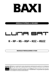
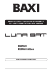
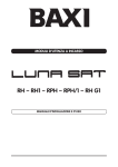
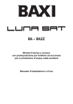
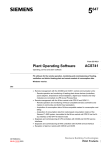
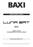
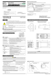
1
RC
it
moduli d’utenza a incasso
en
built-in user modules
manuale d’installazione e d’uso
installation and operating manual
UNA PAROLA AL PROPRIETARIO DEL PRODOTTO BAXI
La nostra Azienda ritiene che il Suo nuovo prodotto BAXI soddisferà tutte le Sue esigenze.
L’acquisto di un prodotto BAXI garantisce quanto Lei si aspetta: un buon funzionamento ed un uso semplice
e razionale.
Quello che Le chiediamo è di non mettere da parte queste istruzioni senza averle prima lette: esse contengono informazioni utili per una corretta ed efficiente gestione del Suo prodotto.
Attenzione: le parti dell’imballo (sacchetti in plastica, polistirolo ecc.) non devono essere lasciate alla portata dei bambini in quanto
potenziali fonti di pericolo.
BAXI S.p.A., tra i leader in Europa nella produzione di caldaie e sistemi per il riscaldamento ad alta tecnologia, è certificata da CSQ per i sistemi di gestione per la qualità (ISO 9001) per l’ambiente (ISO 14001) e per la salute e sicurezza
(OHSAS 18001). Questo attesta che BAXI S.p.A. riconosce come propri obiettivi strategici la salvaguardia dell’ambiente,
l’affidabilità e la qualità dei propri prodotti, la salute e sicurezza dei propri dipendenti.
L’azienda attraverso la propria organizzazione è costantemente impegnata a implementare e migliorare tali aspetti a
favore della soddisfazione dei propri clienti.
MANUALE D’INSTALLAZIONE E D’USO
2
910.370.1 - it
INDICE
1. Descrizione
2. Avvertenze prima dell’installazione
4
4
ISTRUZIONI DI INSTALLAZIONE: ALLACCIAMENTO IDRAULICO
3. Prescrizioni impianto centralizzato
4. Montaggio cassa dima
5. Montaggio apparecchio
6. Caratteristiche portata/perdite di carico 7. Contatore consumo acqua sanitaria
5
9
10
12
14
ISTRUZIONI DI INSTALLAZIONE: ALLACCIAMENTO ELETTRICO
8. Allacciamento elettrico
9. Schema elettrico
10. Collegamento del termostato ambiente
15
16
16
ISTRUZIONI DI INSTALLAZIONE: CONTABILIZZAZIONE CALORE
11. Contabilizzazione Calore
12. Sistema automatico di lettura via Onde Radio
17
18
ISTRUZIONI DI MESSA IN SERVIZIO E UTILIZZO
13. Riempimento impianto
14. Sfiato aria e sblocco pompa
21
21
ISTRUZIONI DI MANUTENZIONE
15. Pulizia del filtro entrata riscaldamento
16. Schema funzionale
17. Fine vita prodotto
18. Caratteristiche tecniche
MANUALE D’INSTALLAZIONE E D’USO
22
23
24
24
3
910.370.1 - it
PREFAZIONE
I moduli d’utenza LUNA SAT sono apparecchi che permettono la gestione autonoma del riscaldamento in impianti centralizzati, con relativa contabilizzazione del calore distribuito nella singola unità abitativa (appartamento o zona da gestire
autonomamente) e con possibilità di trasmettere il consumo di calore.
Le note ed istruzioni tecniche che seguono sono rivolte agli installatori per dar loro la possibilità di effettuare una perfetta
installazione.
Le istruzioni riguardanti l’uso dell’apparecchio sono contenute nella sezione “Istruzione di messa in servizio e utilizzo” di
tale manuale.
ATTENZIONE:
- Le parti dell’imballo (sacchetti in plastica, polistirolo ecc.) non devono essere lasciate alla portata dei bambini in
quanto potenziali fonti di pericolo.
- L’apparecchio deve essere alloggiato nella cassa/dima prevista a tale scopo.
1. DESCRIZIONE
Il modulo d’utenza LUNA SAT RC è disponibile in 2 modelli:
LUNA SAT
Modalità trasmissione dati
LUNA SAT RC
radio (wireless)
LUNA SAT RC MB
cavo (Mbus)
I modelli RC possono funzionare sia in riscaldamento che in raffrescamento.
2. AVVERTENZE PRIMA DELL’INSTALLAZIONE
Questi apparecchi devono essere inseriti in un impianto di riscaldamento centralizzato, previsto a tale scopo, compatibilmente alle loro prestazioni e potenze.
Il tecnico installatore deve essere abilitato all’installazione degli apparecchi per riscaldamento secondo il D.M. 22 gennaio
2008, n° 37 e relativo Regolamento di Attuazione.
La prima messa in funzione deve essere effettuata dal Servizio di Assistenza Tecnica autorizzato dalla BAXI S.p.A. rilevabile dal foglio allegato.
Il mancato rispetto di quanto sopra comporta il decadimento della garanzia.
Prima di collegare l’apparecchio è indispensabile effettuare:
• Un lavaggio accurato di tutte le tubazioni dell’impianto onde rimuovere eventuali residui delle filettature, saldature ed
i solventi presenti eventualmente nei vari componenti del circuito di riscaldamento.
L’apparecchio non è destinato a essere usato da persone (bambini compresi) le cui capacità fisiche, sensoriali
o mentali siano ridotte, oppure con mancanza di esperienza o di conoscenza, a meno che esse abbiano potuto
beneficiare, attraverso l’intermediazione di una persona responsabile della loro sicurezza, di una sorveglianza o
di istruzioni riguardanti l’uso dell’apparecchio.
MANUALE D’INSTALLAZIONE E D’USO
4
910.370.1 - it
ISTRUZIONI DI INSTALLAZIONE:
ALLACCIAMENTO IDRAULICO
3. PRESCRIZIONI IMPIANTO CENTRALIZZATO
Vengono fornite di seguito alcune indicazioni generali riguardanti la realizzazione dell’impianto centralizzato. Si
ricorda che per tali tipologie di impianto è sempre necessaria una mirata progettazione eseguita nel rispetto dello
stato dell’arte della termotecnica e della normativa vigente (come previsto dalla Legge N° 10/91) con obiettivo di
garantire condizioni ottimali di benessere ambientale, risparmio energetico e ridotto impatto ambientale.
Si consiglia di installare caldaie in cascata (preferibilmente a condensazione e a bassa emissione di sostanze inquinanti)
di taglia opportuna per ottimizzare il rendimento di impianto a seconda dei carichi stagionali, della richiesta delle utenze
e dei picchi di richiesta acqua calda sanitaria. La potenza massima installata deve tenere conto di un fattore di contemporaneità d’uso in modo da non sovradimensionare il generatore con conseguente bassa efficienza di utilizzo.
L’impianto centralizzato deve alimentare i vari piani dell’edificio attraverso colonne montanti posizionate in corrispondenza delle scale o di vani tecnici preferibilmente ispezionabili.
L’uso di un separatore idraulico posto a valle del generatore di calore è sempre consigliato in quanto permette di svincolare la circolazione nel generatore dalla circolazione nelle colonne.
L’impianto centralizzato deve essere dotato dei seguenti dispositivi:
• Caricamento automatico
• Sistema di espansione dimensionato tenendo conto della capacità totale dell’impianto stesso
• Valvola di sicurezza contro la sovrapressione dimensionata secondo quanto prescritto dalle normative vigenti (Raccolta
“R” ISPESL).
Ogni colonna opportunamente dimensionata deve essere dotata di circolatore (preferibilmente a velocità variabile in funzione della richiesta dei moduli), di valvole d’intercettazione e di valvola di bilanciamento dinamico. Nelle sommità delle
colonne devono essere installate dei dispositivi di scarico automatico dell’aria.
I tratti di alimentazione devono presentare la stessa perdita di carico in modo che il sistema permetta l’alimentazione
bilanciata di tutti i sistemi di utenza. La tipologia consigliata è il tre colonne con ritorno inverso.
Colonne e collettori devono essere ben coibentati.
Nel computo delle perdite di carico si deve considerare anche le perdite di carico del circuito di riscaldamento a valle del
modulo d’utenza (R = 0,3 KPa/m per metro lineare + perdite localizzate) e la perdita di carico del Modulo stesso.
È possibile installare un by-pass qualora l’impianto non sia dotato di pompa modulante.
In caso di impianto funzionante anche in regime di raffrescamento, in parallelo al generatore di calore, deve essere installato il sistema di produzione acqua refrigerata. Il dimensionamento delle tubazioni va eseguito in base al maggiore
dei due carichi (invernale o estivo). Coibentare opportunamente le tubazioni per evitare la condensa dell’umidità dell’aria
sulle superfici fredde.
MANUALE D’INSTALLAZIONE E D’USO
5
910.370.1 - it
CR_0316 / 1002_2002
Figura 1: Schema indicativo impianto: produzione centralizzata acqua calda sanitaria
MANUALE D’INSTALLAZIONE E D’USO
6
910.370.1 - it
0606_0904 / CR_0013
Figura 2: Schema disposizione sul piano
Lo schema nella figura 2 è indicativo e riporta solamente le tubazioni di alimentazione dei singoli moduli di utenza.
L’impianto di riscaldamento all’interno della zona asservita dal modulo deve essere realizzato alimentando i corpi scaldanti
secondo i normali metodi.
3.1 DATI GENERALI PER IL DIMENSIONAMENTO
- Campo temperatura acqua impianto centralizzato: - Pressione massima acqua impianto centralizzato: - Portata alimentazione modulo (di progetto): - Velocità massima fluido termovettore consigliata: - Perdita di carico modulo: 60 - 75 °C
4 bar
700 ÷ 1000 l/h
1 ÷ 1,5 m/s
15 KPa a 700 l/h (si veda § 6)
Riportiamo di seguito alcuni dati, puramente indicativi, utili al dimensionamento di massima:
TABELLA: FABBISOGNO TERMICO – SUPERFICIE RISCALDATA
Superficie da riscaldare
(m2)
Fabbisogno termico (*)
Con F1 = 20 W/m3
(kW)
Fabbisogno termico (*)
Con F2 = 30 W/m3
(kW)
Fabbisogno termico (*)
Con F3 = 45 W/m3
(kW)
60
3,6
5,4
8,1
70
4,2
6,3
9,5
80
4,8
7,2
10,8
90
5,4
8,1
12,2
100
6,0
9
13,5
110
6,6
9,9
14,9
120
7,2
10,8
16,2
130
7,8
11,7
17,6
140
8,4
12,6
18,9
150
9,0
13,5
20,3
(*)Carico termico volumetrico “F”: 20 - 30 - 45 W/m3 con Δt = 25 K;
Altezza volume da riscaldare = 3 m
Δt = differenza di temperatura tra interno ed esterno (T interna = 20 °C, T esterna = - 5°C)
F1 = 20 W/m3 edifici con ottimo grado di isolamento
F2 = 30 W/m3 edifici con buono grado di isolamento
F3 = 45 W/m3 edifici con scarso grado di isolamento
MANUALE D’INSTALLAZIONE E D’USO
7
910.370.1 - it
TABELLA: FABBISOGNO TERMICO – PORTATA ACQUA CIRCUITO RISCALDAMENTO
Potenza termica
Riscaldamento
(kW)
Portata circuito
Riscaldamento
Con ΔT = 15 K
(l/h)
Portata circuito
Riscaldamento
Con ΔT = 20 K
(l/h)
7
401
301
8
459
344
9
516
387
10
573
430
11
631
473
12
688
516
13
745
559
14
803
602
15
860
645
16
917
688
17
975
731
18
1032
774
19
1089
817
20
1147
860
ΔT = Differenza Temperatura Mandata – Ritorno Modulo d’utenza
TABELLA: FABBISOGNO RAFFRESCAMENTO – SUPERFICIE RAFFREDDATA
Superficie
da raffrescare
(m2)
Fabbisogno
raffrescamento (*)
Con F1 = 15 W/m3
(kW)
Fabbisogno
raffrescamento (*)
Con F2 = 25 W/m3
(kW)
Fabbisogno
raffrescamento (*)
Con F3 = 40 W/m3
(kW)
60
2,7
4,5
6,3
70
3,2
5,3
7,4
80
3,6
6,0
8,4
90
4,1
6,8
9,5
100
4,5
7,5
10,5
110
5,0
8,3
11,6
120
5,4
9,0
12,6
(*)Carico termico volumetrico “F”: 15 - 25 - 40 W/m3 con Δt = 8 K (ventilconvettori)
Altezza volume da raffrescare = 3 m
Δt = differenza di temperatura tra interno ed esterno (T interna = 26 °C, T esterna = + 34°C)
F1 = 15 W/m3 edifici con ottimo grado di isolamento ed ottima protezione alla radiazione solare
F2 = 25 W/m3 edifici con buono grado di isolamento e buona protezione alla radiazione solare
F3 = 40 W/m3 edifici con scarso grado di isolamento e scarsa protezione alla radiazione solare
TABELLA: FABBISOGNO RAFFRESCAMENTO – PORTATA ACQUA CIRCUITO RAFFRESCAMENTO
Potenza termica
Raffrescamento
(kW)
Portata circuito
Raffrescamento
Con ΔT = 5 K
(l/h)
7
1204
8
1376
9
1548
10
1720
11
1892
12
2064
13
2236
ΔT = Differenza Temperatura Mandata – Ritorno Modulo d’utenza
Temperatura mandata : 12°C
Temperatura ritorno : 7°C
MANUALE D’INSTALLAZIONE E D’USO
8
910.370.1 - it
4. MONTAGGIO CASSA DIMA
Il modulo LUNA SAT va installato all’interno della cassa/dima che è fornita in un imballo a parte.
Assicurarsi che il modello della cassa dima sia corretto (L= 450 mm).
La cassa/dima deve essere inserita nel muro in una nicchia ricavata a tale scopo (dimensioni riportate in figura 3 e 4 e
bloccata con le apposite zanche laterali. Assicurarsi che l’installazione permetta una agevole manutenzione.
È possibile installare la cassa su tre posizioni a seconda della disposizione idraulica prescelta:
1) alimentazione sinistra-destra
2) alimentazione alto-basso
3) alimentazione basso alto
La disposizione destra-sinistra non è consigliata.
La porta e il telaio vanno sempre montati con la serratura nella parte alta.
La porta e la cornice in colore bianco devono essere rimosse e inserite solamente alla fine della fase di installazione (verificare che a corredo della cassa vi sia anche la chiave per l’apertura della porta).
La cornice permette una regolazione in profondità agendo sui 4 dadi con alette posti nelle guide trasversali. E’ così possibile appoggiare la cornice all’intonaco e rimuoverla in caso di tinteggiatura della parete.
CR_0319 / 1003_0101
Eseguire la posa in opera dell’impianto partendo dalla posizione degli attacchi idrici presenti nelle traverse della cassa
dima (rientranza in cassa: 65 mm).
Consigliamo di installare la cassa nel vano scala all’esterno dell’appartamento da riscaldare.
L = 450 mm
H = 450 mm
P = 110 mm
II
III
CR_0322 / 1003_1601
I
Figura 3: cassa/dima
MANUALE D’INSTALLAZIONE E D’USO
9
910.370.1 - it
5. MONTAGGIO APPARECCHIO
CR_0320 / 1003_1602
Dopo aver completato le opere murarie inserire il modulo LUNA SAT nella cassa/dima e fissarlo agli attacchi dei quattro
rubinetti già presenti nella cassa/dima.
Bloccare la scatola elettrica alla staffa della cassa con il dado fornito in dotazione.
Figura 4: Attacchi e dimensioni
Legenda
CONNESSIONI IMPIANTO CENTRALIZZATO
IP: Ingresso primario da impianto centralizzato G3/4” M
UP: uscita primario a impianto centralizzato G3/4” M
CONNESSIONI IMPIANTO RISCALDAMENTO MODELLI MONOZONA
MR: mandata impianto riscaldamento G3/4” M
RR: ritorno impianto riscaldamento G3/4” M
CONNESSIONI CONTATORI CONSUMO ACQUA SANITARIA
EC1: Entrata acqua sanitaria a contatore G 3/4”
EC2: Entrata acqua sanitaria a secondo contatore G 3/4’’
EC3: Entrata acqua sanitaria a terzo contatore G 3/4’’
UC1: Uscita acqua sanitaria da contatore G 3/4” M
UC2: Uscita acqua sanitaria da secondo contatore G3/4’’ M
UC3: Uscita acqua sanitaria da terzo contatore G3/4’’
AE: Foro passaggio cavi
MANUALE D’INSTALLAZIONE E D’USO
10
910.370.1 - it
Figura 4B
Bloccare la scatola elettrica alla staffa della cassa/dima con l’apposito dado fornito con il modulo d’utenza (vedi particolare “A”).
MANUALE D’INSTALLAZIONE E D’USO
11
910.370.1 - it
6. CARATTERISTICHE PORTATA/PERDITE DI CARICO
Tali modelli sono dotati di valvola di bilanciamento (figura 6). Questo dispositivo va utilizzato per bilanciare la portata
d’acqua circolante nel singolo modulo in caso di non ottimale distribuzione nelle ramificazioni di alimentazione. In figura 5
è riportata la curva Portata – Perdita di Carico con valvola di bilanciamento in posizione di massima apertura.
PERDITA DI CARICO (mH20)
1007_1401
PERDITA DI CARICO CIRCUITO RISCALDAMENTO mod. LUNA SAT RC
Figura 5: Curve Portata – Perdita di carico
PORTATA ACQUA (l/h)
In figura 6 sono riportate le curve Portata – Perdita di Carico con diversi gradi di posizionamento della manopola.
La curva “A” fa riferimento ad un giro di apertura della manopola partendo dalla posizione di chiusura. Le curve successive indicano 1/2 giro di apertura in più della manopola rispetto alla curva precedente. La curva “H” rappresenta la valvola
completamente aperta.
PERDITA DI CARICO (mH20)
1007_1402
NOTA:
per ridurre la portata agire in
senso orario sulla manopola.
CR_0317 / 1003_1606
CURVA CARATTERISTICA VALVOLA BILANCIAMENTO
Figura 6: Valvola bilanciamento frontale G3/4”
MANUALE D’INSTALLAZIONE E D’USO
PORTATA ACQUA (l/h)
12
910.370.1 - it
6.1 BY-PASS
CR_0325 / 1003_2401
Il satellite è dotato di by-pass automatico con apertura per Δp=4 m. H2O.
La portata per by-pass in posizione di apertura è di 100 l/h.
In caso di presenza di pompe modulanti è possibile rimuovere il by-pass togliendo il tubo di collegamento e tappando le
due uscite con due calotte cieche da G 1/2” e G 3/4” (particolare in figura 7).
A seconda della fornitura il modulo d’utenza può essere dotato o meno del tubo di by-pass che è disponibile come accessorio.
Figura 7: smontaggio tubo by-pass
MANUALE D’INSTALLAZIONE E D’USO
13
910.370.1 - it
7. CONTATORE CONSUMO ACQUA SANITARIA (accessorio a richiesta)
Un Kit contatore per la misura del consumo dell’acqua sanitaria è disponibile come accessorio.
Tali Modelli possono alloggiare un contatore per rilevare il consumo d’acqua calda proveniente da un sistema ad accumulo centralizzato, un secondo contatore per rilevare il consumo d’acqua fredda sanitaria della singola utenza ed un ulteriore
terzo contatore per rilevare il consumo di acqua di raccolta piovana.
Il kit è composto da un contatore volumetrico SIEMENS WFW30 con quadrante e trasmissione radio dei dati (stesse caratteristiche del contabilizzatore di calore: si veda §11) e da due rubinetti G 3/4” che vanno alloggiati all’interno del telaio
della cassa dima nelle forature previste a tale scopo (tre posizioni).
Per ulteriori informazioni sul contatore vedere anche le istruzioni SIEMENS fornite a corredo dello stesso.
Figura 8: Contatori consumo acqua sanitaria
I° contatore
Entrata acqua sanitaria da contabilizzare: attacco idraulico EC1 (G 3/4”)
Uscita acqua sanitaria contabilizzata: attacco idraulico UC1 (G 3/4”)
II° contatore
Entrata acqua sanitaria da contabilizzare: attacco idraulico EC2 (G 3/4”)
Uscita acqua sanitaria contabilizzata: attacco idraulico UC2 (G 3/4”)
III° contatore
Entrata acqua sanitaria da contabilizzare: attacco idraulico EC3 (G 3/4”)
Uscita acqua sanitaria contabilizzata: attacco idraulico UC3 (G 3/4”)
MANUALE D’INSTALLAZIONE E D’USO
14
910.370.1 - it
ISTRUZIONI DI INSTALLAZIONE:
ALLACCIAMENTO ELETTRICO
8. ALLACCIAMENTO ELETTRICO
L’apparecchio è venduto completo di collegamenti elettrici e di cavo di alimentazione.
La sicurezza elettrica dell’apparecchio è raggiunta soltanto quando lo stesso è correttamente collegato ad un’efficace
impianto di messa a terra, eseguito come previsto dalle vigenti Norme di sicurezza sugli impianti (D.M. 22 gennaio 2008,
n° 37 e relativo Regolamento di Attuazione).
L’apparecchio va collegato elettricamente ad una rete di alimentazione 230 V monofase + terra mediante il cavo a tre fili
in dotazione rispettando la polarità FASE (L) - NEUTRO (N).
L’allacciamento deve essere effettuato tramite un interruttore ad azione bipolare con apertura dei contatti di almeno 3
mm.
In caso di sostituzione del cavo di alimentazione deve essere utilizzato un cavo armonizzato “HAR H05 VV-F” 3x1 mm2
con diametro massimo di 8 mm.
8.1 ACCESSO ALLA MORSETTIERA DI ALIMENTAZIONE
• Togliere tensione all’apparecchio mediante l’interruttore bipolare.
• Verificare che la lampada luminosa dell’interruttore sia spenta.
• Svitare le viti del coperchio della scatola elettrica e rimuoverlo.
• Il fusibile, del tipo rapido da 2A, è incorporato nella morsettiera di alimentazione.
940225_0715
(L) = FASE marrone
(N) = NEUTRO celeste
= TERRA giallo-verde
fusibile
morsettiera
Figura 9: Fusibili protezione elettrica
MANUALE D’INSTALLAZIONE E D’USO
15
910.370.1 - it
9. SCHEMA ELETTRICO
10. COLLEGAMENTO DEL TERMOSTATO AMBIENTE (Si veda DPR 26 Agosto 1993 n° 412)
L’impianto deve essere dotato di termostato ambiente (DPR 26 Agosto 1993 n° 412 articolo 7 comma 6) per il controllo
della temperatura nei locali.
Per la connessione di tale dispositivo seguire quanto di seguito riportato:
• Accedere alle parti elettriche come descritto nel paragrafo 8.
• Togliere il ponticello presente sui morsetti (1) e (2) della morsettiera principale (si veda schema elettrico del § 9).
• Introdurre il cavo a due fili attraverso i passacavi della scatola elettrica e collegarlo a questi due morsetti utilizzare un
cavo armonizzato “HAR H05 VV-F” 2 x 0,75 mm2 con diametro massimo di 8 mm.
Nel caso di funzionamento in raffrescamento è necessario utilizzare un termostato ambiente predisposto per il funzionamento estivo. Selezionato il funzionamento estivo all’innalzarsi della temperatura ambiente, il termostato deve chiudere il
contato permettendo l’alimentazione del satellite con l’acqua di raffrescamento.
MANUALE D’INSTALLAZIONE E D’USO
16
910.370.1 - it
ISTRUZIONI DI INSTALLAZIONE:
CONTABILIZZAZIONE CALORE
11. CONTABILIZZAZIONE CALORE
I Moduli sono dotati di serie di contabilizzatore di calore elettronico SIEMENS MEGATRON.
Questo dispositivo effettua la misura dei consumi di calore della zona asservita al Modulo d’utenza.
L’unità elettronica comprende un display ad otto cifre LCD. La tensione di alimentazione è di DC 3 V ed è fornita tramite
una batteria al litio (durata 8 anni). Sul fronte del display c’è un pulsante, con cui interrogare l’apparecchio.
L’apparecchio può essere ruotato di 360° e inclinato di 90°.
Il display dell’apparecchio dispone di due livelli con i quali possono essere visualizzati i seguenti dati :
• Sommatoria dell’energia consumata dal giorno di lettura.
• Test dei segmenti
• Consumo attuale
• Portata attuale
• Temperatura di mandata attuale
• Temperatura di ritorno attuale
• Delta T, attuale tra le due temperature
• Ore di funzionamento dal primo avviamento
• Data del giorno di lettura
• Consumo di energia dell’anno precedente.
• Codice di verifica
• Consumo di energia totale, da quando è stato installato
• Indicazione delle anomalie (fare riferimento alla sezione seguente)
Il modulo d’utenza è dotato di contabilizzatore caldo/freddo e può conteggiare i consumi del regime di raffrescamento.
Le unità di misura sono °C or K, kWh, m3/h, kW, e ore.
Il display indica come standard la somma del consumo per riscaldamento.
Segnali di anomalia
L’apparecchio esegue automaticamente dei controlli diagnostici ed è in grado di indicare le anomalie riscontrate. Esso
divide le anomalie in due categorie.
• Anomalie temporanee: che non provocano problemi di funzionamento all’apparecchio. In questo caso, il display lampeggia per 32 secondi, poi torna al funzionamento normale;
• Anomalie gravi: non permettono il funzionamento dell’apparecchio. In questo caso, il display indica alternativamente
il codice dell’anomalia e la data in cui è comparsa per la prima volta.
I valori di misura conteggiati fino a quel momento, rimangono in memoria.
0606_1021
Per ulteriori informazioni vedere anche le istruzioni SIEMENS fornite a corredo del contabillizatore.
Figura 10: Display contabilizzatore
I dati di contabilizzazione possono essere anche trasmessi via radio ad un dispositivo di ricezione a distanza
(espansione sistema Radio).
MANUALE D’INSTALLAZIONE E D’USO
17
910.370.1 - it
12. SISTEMA AUTOMATICO DI LETTURA VIA ONDE RADIO
Tale sistema permette la gestione di tutti i consumi dell’edificio da un unica postazione risparmiando così sui tempi di
lettura e proteggendo allo stesso tempo la privacy degli utenti. La frequenza di trasmissione è di 868 MHz prevista dal
piano nazionale per la trasmissione radio (standard europeo). La durata e la potenza del segnale radio sono irrilevanti e
non sono assolutamente connesse ai problemi di “elettrosmog”.
I contabilizzatori di calore dei vari Moduli d’utenza trasmettono i consumi tramite un segnale ad onde radio a delle apposite antenne di piano (WTT16) che ricevono e memorizzano i dati. I consumi possono essere letti collegandosi via radio
ad una qualunque delle antenne di piano con un Personal computer o collegandosi via cavo ad una antenna con uscita
seriale oppure da postazione remota tramite un modem (GSM).
• Lettura locale via cavo dall’antenna WTT16.232 con interfaccia RS232:
tramite un PC (con software di lettura dati ACS26) collegato con un cavo seriale (figura 11b caso 1).
• Lettura locale via radio delle antenne di piano WTT16:
tramite un PC (con software di lettura dati ACS26) collegato al modulo radio WTZ.RM (figura 11b caso 2).
• Lettura a distanza via rete telefonica GSM dall’antenna Gateway WTX16.GSM:
Tramite un PC (con software di lettura ACS26 e modem GSM + scheda telefonica) (figura 11b caso 3).
A seconda dei casi è necessario utilizzo dei seguenti componenti aggiuntivi disponibili come accessori:
•
•
•
•
•
ANTENNA PIANO WTT16
ANTENNA USCITA SERIALE WTT16.232 (lettura locale tramite PC)
ANTENNA GATEWAY WTX16.GSM (lettura via telefonica tramite PC)
MODULO RADIO SIEMECA WTZ.RM PER PC (lettura via radio tramite PC)
SOFTWARE LETTURA ACS26 (per PC)
Durante l’installazione, non sono richieste particolari procedure di messa in servizio per la trasmissione radio, tutti i componenti del sistema si configurano automaticamente per la trasmissione dei segnali. Queste caratteristiche garantiscono
una messa in servizio rapida e senza problemi e una gestione semplice del sistema.
Il sistema Radio deve essere installato rispettando quanto riportato:
• Campo di ricezione medio delle antenne WTT16: raggio di 25 metri sul piano dove sono installate e 15 metri sul piano
superiore e inferiore (Installare le antenne WTT16 una per piano, un piano si e uno no).
• Capacità del sistema: max. 12 antenne WTT16 (o 11 Antenne WTT16 + 1 Antenna GATEWAY WTX16) con ricezione
max. di 500 contatori di consumo.
• Durata di servizio della antenna a batteria WTT16: minimo 6 anni più 1 anno di riserva durante il quale viene inviato un
messaggio di “batteria in esaurimento”
• Durata di servizio dei contabilizzatori di calore: 6 anni più 15 mesi di riserva
• L’antenna WTX16.GSM Gateway deve essere alimentato a tensione di rete.
Le antenne di piano (WTT16) devono essere fissate a muro con il tassello fornito in dotazione ad una parete del vano scale
ad una altezza che non permetta manomissioni.
L’antenna Gateway (WTX16.GSM) va installata nell’atrio dell’edificio da contabilizzare (tale componente richiede l’alimentazione elettrica di rete).
MANUALE D’INSTALLAZIONE E D’USO
18
910.370.1 - it
0607_0219 / CR_0027
ANTENNA DI PIANO
TRASMISSIONE ONDE RADIO 868 MHz
TRASMISSIONE ONDE RADIO 868 MHz
TRASMISSIONE ONDE RADIO 868 MHz
ANTENNA
DI PIANO
TRASMISSIONE ONDE RADIO 868 MHz
TRASMISSIONE TELEFONICA
GSM
TRASMISSIONE ONDE RADIO 868 MHz
(VEDERE OPZIONI
FIGURA 11B)
Figura 11 A: Sistema automatico di lettura via Onde Radio
MANUALE D’INSTALLAZIONE E D’USO
19
910.370.1 - it
0607_0220 / CR_0033
Figura 11 B: Opzioni lettura
MANUALE D’INSTALLAZIONE E D’USO
20
910.370.1 - it
12.1 MESSA IN SERVIZIO
La messa in servizio del Sistema radio avviene in più fasi:
• Impostare le antenne WTT16 in modalità di messa in servizio (premere il pulsante rosso MODE su ogni antenna WTT16).
• A questo punto, le antenne WTT16 si autoconfigurano creando automaticamente una rete virtuale di comunicazione.
• Impostare i contabilizzatori di calore in modalità di messa in servizio. premendo il pulsante sul frontale. Avviata la
modalità tutti contabilizzatori lanciano un segnale di messa in servizio alle antenne WTT16.
• Una volta ricevuti tutti i contabilizzatori in campo, per completare la messa in servizio del sistema, impostare le antenne
in modalità standard (premere il pulsante blu su ogni antenna WTT16).
12.2 FUNZIONAMENTO
Durante il funzionamento automatico del sistema, le antenne WTT16 e l’antenna GATEWAY WTX16.GSM si scambiano
giornalmente i dati di consumo dei contatori in modo da avere in ogni singola antenna i dati completi dell’edificio. Eventualmente i dati di tutto l’edificio possono essere aggiornati manualmente senza dover aspettare lo scambio giornaliero.
12.3 FORMATO DATI
I dati di consumo sono codificati in formato XML o in codice ASCII per essere gestiti con qualsiasi editore (Notepad,
Excel..ecc).
Per ulteriori informazioni leggere anche quanto riportato nei manuali dei singoli componenti.
ISTRUZIONI DI MESSA IN SERVIZIO E UTILIZZO
13. RIEMPIMENTO IMPIANTO
Prima dell’ avvio del modulo d’utenza aprire le valvole di intercettazione poste sugli attacchi idraulici e verificare in sala
termica e nelle colonne di distribuzione il valore della pressione di caricamento impianto (< 3 bar).
L’impianto centralizzato deve avere un dispositivo di caricamento automatico.
14. FUNZIONAMENTO
14.1 AVVIO
Procedere come di seguito descritto per le corrette operazioni di avvio:
• Alimentare il modulo elettricamente.
• Verificare che l’impianto sia pieno, alla pressione giusta (si veda § 13) e in temperatura (65 ÷ 75°C).
• Premere il l’interruttore luminoso presente nel coperchio della scatola elettrica.
• Regolare il termostato ambiente alla temperatura desiderata.
Alla richiesta di calore da parte del termostato ambiente l’acqua proveniente dal sistema centralizzato inizierà a circolare nei corpi scaldanti della zona asservita dal modulo d’utenza.
14.2 SPEGNIMENTO PARZIALE
Agire sul termostato ambiente/ Programmatore riscaldamento in modo da escludere il funzionamento in riscaldamento
(abbassamento della temperatura ambiente impostata).
14.3 SPEGNIMENTO TOTALE
Togliere tensione all’apparecchio agendo sull’interruttore luminoso e sull’interruttore bipolare.
MANUALE D’INSTALLAZIONE E D’USO
21
910.370.1 - it
ISTRUZIONI DI MANUTENZIONE
Per un funzionamento regolare ed economico dei Moduli di utenza, è necessario che essi siano controllati e revisionati
periodicamente ogni due anni circa.
15. PULIZIA DEL FILTRO ENTRATA RISCALDAMENTO
Tali apparecchi sono dotati di un filtro acqua riscaldamento posizionato sull’entrata dell’acqua proveniente dall’impianto
centralizzato.
Per la pulizia procedere come di seguito descritto:
• Chiudere tutti i rubinetti di intercettazione posti sugli attacchi idraulici del Modulo;
• Svuotare il circuito di riscaldamento;
• Svitare il tappo presente nelle sommità del filtro ed estrarre la cartuccia cilindrica interna e eliminare le impurità eventualmente presenti.
• Se necessario rimuovere il tubo di by-pass.
Figura 12: Smontaggio filtro circuito riscaldamento
MANUALE D’INSTALLAZIONE E D’USO
22
910.370.1 - it
16. SCHEMA FUNZIONALE
MANUALE D’INSTALLAZIONE E D’USO
23
910.370.1 - it
17. FINE VITA PRODOTTO
Questo prodotto è stato realizzato con materiali che non inquinano l’ambiente, alla fine del suo ciclo di vita non dovrà
essere trattato come un rifiuto domestico ma dovrà essere consegnato al punto più vicino di raccolta per il riciclo delle
apparecchiature.
Lo smaltimento deve essere effettuato in accordo con le regole ambientali vigenti per lo smaltimento dei rifiuti.
18. CARATTERISTICHE TECNICHE
Modelli moduli d’utenza LUNA SAT
RC
Modelli con pompa
-
Pressione massima circuito riscaldamento
bar
4
l
1,5
Tensione alimentazione elettrica
V
230
Frequenza di alimentazione elettrica
Hz
50
Potenza elettrica nominale
W
15
Larghezza cassa contenimento
mm
450
Altezza cassa contenimento
mm
450
Profondità cassa contenimento
mm
110
Peso netto (escluso cassa dima)
kg
3,2
Contenuto d’acqua
La BAXI S.P.A. nella costante azione di miglioramento dei prodotti, si riserva la possibilità di modificare i dati espressi
in questa documentazione in qualsiasi momento e senza preavviso. La presente documentazione è un supporto informativo e non considerabile come contratto nei confronti di terzi.
MANUALE D’INSTALLAZIONE E D’USO
24
910.370.1 - it
TO THE OWNER OF THIS BAXI APPLIANCE
We are confident your new BAXI appliance will meet all your requirements.
All BAXI products have been designed to give you what you are looking for: good performance combined
with simple and rational use.
Please do not put away this booklet without reading it first as it contains some useful information which will
help you to operate your appliance correctly and efficiently.
Caution: Do not leave any packaging (plastic bags, polystyrene, etc.) within reach of children, as it is a potential source of danger.
BAXI S.p.A., a leading European manufacturer of hi-tech boilers and heating systems, has developed CSQ-certified
quality management (ISO 9001), environmental (ISO 14001) and health and safety (OHSAS 18001) systems. This means
that BAXI S.p.A. includes among its objectives the safeguard of the environment, the reliability and quality of its products,
and the health and safety of its employees.
Through its organisation, the company is constantly committed to implementing and improving these aspects in favour
of customer satisfaction.
INSTALLATION AND OPERATING MANUAL
26
910.370.1 - en
CONTENTS
1. Description 2. Instructions prior to installation 28
28
INSTALLATION INSTRUCTIONS: HYDRAULIC CONNECTIONS
3. Centralised system requirements 4. Mounting the template casing 5. Mounting the appliance 6. Flow rate/pressure drop characteristics 7. Domestic water meter 29
33
34
36
38
INSTALLATION INSTRUCTIONS: ELECTRICAL CONNECTIONS
8. Electrical connections
9. Wiring diagram 10. Connecting the ambient thermostat 39
40
40
INSTALLATION INSTRUCTIONS: HEAT METERING
11. Heat metering
12. Automatic radio wave reading system 41
42
START-UP AND OPERATING INSTRUCTIONS
13. Filling the system 14. Air vent and pump release 45
45
MAINTENANCE INSTRUCTIONS
15. Cleaning the central heating inlet filter 16. Functional diagram 17. Disposal 18. Technical specifications INSTALLATION AND OPERATING MANUAL
46
47
48
48
27
910.370.1 - en
FOREWORD
The LUNA SAT user modules make it possible to independently manage heating requirements in centralised systems,
meter the heat distributed to each unit (flat or independently managed area) and transmit heat consumption data.
The following notes and instructions are addressed to fitters to allow them to carry out trouble-free installation.
The operating instructions are contained in the “Start-up and operating instructions” section of this manual.
ATTENTION:
- Do not leave any packaging (plastic bags, polystyrene, etc.) within the reach of children as they are a potential
source of danger.
- The appliance must be housed in the template casing supplied in a separate pack.
1. DESCRIPTION
The LUNA SAT RC user module is available in 2 versions:
LUNA SAT
Data transmission mode
LUNA SAT RC
radio (wireless)
LUNA SAT RC MB
cable (Mbus)
The RC models can work in both the heating and the cooling modes.
2. INSTRUCTIONS PRIOR TO INSTALLATION
These appliances must be inserted in a centralised heating system, especially designed for this purpose, consistently with
their performance levels and power outputs.
The fitter must be legally qualified to install heating appliances.
Initial start-up must be performed by a BAXI - authorised Service Engineer, as indicated on the attached sheet.
Failure to observe the above will render the guarantee null and void.
Do the following before connecting the appliance:
• Carefully flush all the system pipes in order to remove any residual thread-cutting swarf, solder and solvents in the
various heating circuit components.
The appliance is not intended to be used by persons (including children) with reduced physical, sensory or mental
capacities, or who lack experience or knowledge, unless, through the mediation of a person responsible for their
safety, they have had the benefit of supervision or of instructions on the use of the appliance.
INSTALLATION AND OPERATING MANUAL
28
910.370.1 - en
INSTALLATION INSTRUCTIONS:
HYDRAULIC CONNECTIONS
3. CENTRALISED SYSTEM REQUIREMENTS
Some general indications concerning the installation of the centralised heating system are shown below. For
these types of plants, a cutting-edge bespoke design is always necessary in order to ensure ideal conditions of
comfort, save energy and reduce the environmental impact.
Install the boilers in a cascade arrangement (preferably condensation boilers with low pollutant emissions) of a suitable size
to optimise plant performance according to seasonal loads, user demand and Domestic Hot Water demand peaks. The
maximum installed power must consider a simultaneous use factor so as not to oversize the generator and consequently
reduce operating efficiency.
The centralised plant must service the various floors of the building by means of columns positioned in the stairwells or
in utility rooms which should preferably be inspectable.
A hydraulic separator should always be fitted downline from the heat generator as this separates circulation in the generator from circulation in the columns.
The centralised plant must have the following features:
• Automatic filling
• Expansion system sized according to total plant capacity
• Overpressure safety valve sized according to current legislation
Each suitably sized column must be fitted with a circulator (preferably at variable speed depending on the demand of the
modules), on/off valves and a dynamic balancing valve. Automatic air vents must be installed at the top of the columns.
The inlet sections must have the same pressure drop in order to allow the system to balance feed to all the user systems.
The recommended typology is three columns with a reverse return line.
The columns and manifolds must be well lagged.
The heating circuit pressure drops downline from the user module (R = 0.3 KPa/m per linear metre + local pressure drops)
and the pressure drop of the module itself must also be considered when calculating the pressure drops.
A by-pass valve can be fitted if the system is not fitted with a modulating pump.
If the system also operates in the cooling mode, a chilled water refrigeration system must be installed in parallel with the
heat generator. The piping must be sized according to the greater of the two loads (winter or summer). The piping must
be suitably lagged to prevent the humidity in the air from condensing on the cold surfaces.
INSTALLATION AND OPERATING MANUAL
29
910.370.1 - en
CENTRAL
HEATING
CENTRAL
HEATING
CENTRAL
HEATING
DOMESTIC
HOT WATER
DOMESTIC
HOT WATER
DOMESTIC
HOT WATER
CR_0316 / 1004_0704
HEATING PLANT WITH
BOILERS CONNECTED IN A
CASCADE ARRANGEMENT
AND CENTRALISED
DOMESTIC HOT WATER
PRODUCTION
Figure 1: Diagram of plant: centralised domestic hot water production
INSTALLATION AND OPERATING MANUAL
30
910.370.1 - en
CR_0013 / 1004_0705
HOME C
HOME B
HOME A
Figure 2: Floor layout
The indicative diagram in figure 2 only illustrates the feed pipes of the individual user modules.
The heating plant inside the zone controlled by the module must be realised by feeding the heating elements according
to normal methods.
3.1 GENERAL SIZING DATA
- Water temperature range in centralised plant:
- Maximum water pressure in centralised plant: - Module feed flow rate (nominal): - Maximum recommended speed of heat transfer fluid:
- Pressure drop in module 60 - 75 °C
4 bar
700 ÷ 1000 l/h
1 ÷ 1.5 m/s
20 KPa at 700 l/h (see § 6)
Some purely indicative general sizing data is shown below:
TABLE: HEAT DEMAND – HEATED AREA
Area to heat
(m2)
Heat demand (*)
With F1 = 20 W/m3
(kW)
Heat demand (*)
With F2 = 30 W/m3
(kW)
Heat demand (*)
With F3 = 45 W/m3
(kW)
60
3,6
5,4
8,1
70
4,2
6,3
9,5
80
4,8
7,2
10,8
90
5,4
8,1
12,2
100
6,0
9
13,5
110
6,6
9,9
14,9
120
7,2
10,8
16,2
130
7,8
11,7
17,6
140
8,4
12,6
18,9
150
9,0
13,5
20,3
(*) Volumetric heat load “F”: 20 - 30 - 45 W/m3 with Δt = 25 K;
Height of volume to be heated = 3 m
Δt = internal and external temperature difference (internal T = 20 °C, external T = - 5°C)
F1 = 20 W/m3 buildings with an excellent level of insulation
F2 = 30 W/m3 buildings with an good level of insulation
F3 = 45 W/m3 buildings with an low level of insulation
INSTALLATION AND OPERATING MANUAL
31
910.370.1 - en
TABLE: HEAT DEMAND – FLOW OF WATER IN HEATING CIRCUIT
Heating domestic water
heat capacity
(kW)
Flow rate of Heating
circuit with ΔT = 15
K (l/h)
Flow rate of Heating
circuit with ΔT = 20
K (l/h)
7
401
301
8
459
344
9
516
387
10
573
430
11
631
473
12
688
516
13
745
559
14
803
602
15
860
645
16
917
688
17
975
731
18
1032
774
19
1089
817
20
1147
860
ΔT = Difference between User Module Delivery – Return Temperature
TABLE: COOLING DEMAND – COOLED AREA
Area to cool
(m2)
Cooling demand (*)
With F1 = 15 W/m3
(kW)
Cooling demand (*)
With F2 = 25 W/m3
(kW)
Cooling demand (*)
With F3 = 40 W/m3
(kW)
60
2,7
4,5
6,3
70
3,2
5,3
7,4
80
3,6
6,0
8,4
90
4,1
6,8
9,5
100
4,5
7,5
10,5
110
5,0
8,3
11,6
120
5,4
9,0
12,6
(*)Volumetric heat load “F”: 15 - 25 - 40 W/m3 with Δt = 8 K (fancoil heaters)
Height of volume to be cooled = 3 m
Δt = internal and external temperature difference (internal T = 26 °C, external T = + 34°C)
F1 = 15 W/m3 buildings with an excellent insulation level and excellent solar radiation protection
F2 = 25 W/m3 buildings with a good insulation level and good solar radiation protection
F3 = 40 W/m3 buildings with a scarce insulation level and scarce solar radiation protection
TABLE: COOLING DEMAND – FLOW OF WATER IN COOLING CIRCUIT
Heating capacity
Cooling
(kW)
Capacity of cooling
circuit
With ΔT = 5 K
(l/h)
7
1204
8
1376
9
1548
10
1720
11
1892
12
2064
13
2236
ΔT = Difference between User Module Delivery – Return Temperature
Delivery temperature: 12°C
Return temperature: 7°C
INSTALLATION AND OPERATING MANUAL
32
910.370.1 - en
4. MOUNTING THE TEMPLATE CASING
Install the LUNA SAT model inside the casing/template supplied in a separate pack.
Make sure the template casing model is correct (L= 450 mm).
Fit the template/casing in a niche in the wall made for this purpose (dimensions indicated in figures 3 and 4 and secure it
with the relative lateral bent pins. Make sure the installation allows easy access for maintenance.
The casing can be installed in three positions depending on the chosen hydraulic layout:
1) left-right supply
2) high-low supply
3) low-high supply
The right-left layout is not recommended.
Always mount the door and frame with the lock at the top.
Remove the door and white frame and put back after installation (make sure the casing accessories also include the key
for opening the door).
The frame can be depth-adjusted by using the 4 butterfly nuts located in the side guides. It is therefore possible to fit the
frame flush against the plaster and remove it when painting the wall.
CR_0319 / 1003_0101
Assemble the system starting from the position of the water connectors on the lower crossbar of the template (recessed
into the casing by 65 mm). Install the casing in the stairwell outside the apartment to heat.
I
LEFT-RIGHT
II
III
LOW-HIGH
HIGH-LOW
CR_0322 / 1004_0706
L = 450 mm
H = 450 mm
P = 110 mm
Figure 3: casing/template
INSTALLATION AND OPERATING MANUAL
33
910.370.1 - en
5. MOUNTING THE APPLIANCE
CR_0320 / 1003_1602
After completing the masonry work, insert the LUNA SAT module into the casing/template and fix it to the connectors of
the four taps inside the casing/template.
Secure the electrical box to the bracket on the casing with the supplied nut.
Figure 4: Connectors and sizes
Key
CONNECTIONS TO CENTRALISED PLANT
IP: primary inlet from centralised plant G 3 ⁄ 4” M
UP: primary outlet from centralised plant G 3 ⁄ 4” M
HEATING PLANT CONNECTIONS FOR SINGLE-ZONE MODELS
MR: heating plant delivery G 3/4” M
RR: heating plant return G 3/4” M
DOMESTIC WATER METER CONNECTIONS
EC1: Domestic water inlet to meter G 3/4”
EC2: Domestic water inlet to second meter G 3/4”
EC3: Domestic water inlet to third meter G 3/4”
UC1: Domestic water outlet from meter G 3/4” M
UC2: Domestic water outlet from second meter G 3/4” M
UC3: Domestic water outlet from third meter G 3/4”
AE: Hole for cables
INSTALLATION AND OPERATING MANUAL
34
910.370.1 - en
Figure 4B
Secure the electrical box to the bracket on the casing/template using the nut supplied with the user module (see detail
“A”).
INSTALLATION AND OPERATING MANUAL
35
910.370.1 - en
6. FLOW RATE/PRESSURE DROP CHARACTERISTICS
These models are fitted with a balancing valve (figure 6). This device is used to balance the flow of water circulating in the
single module in case of non-optimal distribution in the inlet pipes.
Figure 5 shows the Flow Rate – Pressure Drop curve with balancing valve in the wide open position.
PRESSURE DROP [mH20]
1007_1401
PRESSURE DROP IN HEATING CIRCUIT MOD. LUNA SAT RC
Figure 5: Flow Rate – Pressure Drop curves
WATER FLOW RATE (l/h)
Figure 6 show the curves regarding the HYDRAULIC HEAD LOSS (mH2O) against the WATER FLOW RATE (l/h). To set
the curves, close the valve by turning the knob fully anticlockwise. Turn the knob 1 turn clockwise to set the curve A. The
other curves are each a successive 1/2 turn clockwise from A to H (FULLY OPEN).
PRESSURE DROP [mH20]
1007_1402
N.B.:
to reduce flow, turn the
handle clockwise.
CR_0317 / 1003_1606
CHARACTERISTIC CURVE OF BALANCING VALVE
Figure 6: Front balancing valve G3/4”
INSTALLATION AND OPERATING MANUAL
WATER FLOW RATE (l/h)
36
910.370.1 - en
6.1 BY-PASS
CR_0325 / 1003_2401
The satellite is fitted with an automatic by-pass valve with an aperture for Δp=4 m. H2O.
The flow rate for the by-pass valve in the open position is 100 l/h.
If modulating pumps are installed the by-pass valve can be removed by disconnecting the connection tube and plugging
the two outlets with two blind caps G 1/2” and G 3/4” (see figure 7).
Depending on the supply, the user module can be fitted with the by-pass tube that is available as an accessory.
Figure 7: dismounting the by-pass tube
INSTALLATION AND OPERATING MANUAL
37
910.370.1 - en
7. DOMESTIC WATER METER (available on request)
A meter kit for measuring water consumption is available as an accessory.
These models can house a meter for measuring the consumption of hot water from a centralised boiler system, a second
meter for measuring the domestic cold water consumption of each user and a third meter for measuring rainwater consumption.
The kit comprises a SIEMENS WFW30 with dial and electronic volumetric meter with display and radio data transmission
(featuring the same characteristics as the heat meter: see §11) and two taps G 3/4” housed inside the frame of the casing/
template in the holes made for that purpose (three positions).
For further information on the meter, see the supplied SIEMENS instructions
Figure 8: Domestic water meters
I° meter
Domestic water metering inlet: hydraulic connector EC1 (G 3/4”)
Domestic water metering outlet: hydraulic connector UC1 (G 3/4”)
II° meter
Domestic water metering inlet: hydraulic connector EC2 (G 3/4”)
Domestic water metering outlet: hydraulic connector UC2 (G 3/4”)
III° meter
Domestic water metering inlet: hydraulic connector EC3 (G 3/4”)
Domestic water metering outlet: hydraulic connector UC3 (G 3/4”)
INSTALLATION AND OPERATING MANUAL
38
910.370.1 - en
INSTALLATION INSTRUCTIONS:
ELECTRICAL CONNECTIONS
8. ELECTRICAL CONNECTIONS
The appliance is sold complete with electrical connections and power cable.
This machine is only electrically safe if it is correctly connected to an efficient earth system in compliance with current
safety regulations.
Connect the appliance to a 230V single-phase earthed power supply using the supplied three-pin cable, observing correct LIVE (L) - NEUTRAL (N) polarity.
Use a double-pole switch with a contact separation of at least 3mm.
When replacing the power supply cable, fit a harmonised HAR H05 VV-F’ 3x1 mm2 cable with a maximum diameter of
8mm.
8.1 ACCESS TO THE POWER SUPPLY TERMINAL BLOCK
•
•
•
•
Disconnect the appliance from the mains power supply using the two-pole switch;
Make sure that the switch indicator light is off.
Loosen the screws on the cover of the electrical box and remove it.
The 2A rapid fuse is incorporated in the power terminal block.
940225_0715
(L) = LIVE brown
(N) = NEUTRAL blue
= EARTH yellow-green
Fuse
Terminal block
Figure 9: Electric fuses
INSTALLATION AND OPERATING MANUAL
39
910.370.1 - en
R = RED
V = GREEN
G = YELLOW
G/V = YELLOW/GREEN
M = BROWN
C = LIGHT BLUE
N = BLACK
INPUT
SERVOMOTOR
WIRE COLOURS
POWER TERMINAL BLOCK
FUSE
AUXILIARY TERMINAL
BLOCK
ON/OFF BUTTON
MAINS POWER
INPUT
9. WIRING DIAGRAMS
10. CONNECTING THE AMBIENT THERMOSTAT
The system must be fitted with an ambient thermostat in order to control room temperature.
To connect this device, proceed as follows:
• Access the electrical components as described in section 8.
• Remove the jumper on terminals (1) and (2) of the main terminal block (see wiring diagram in § 9).
• Thread the two-wire cable through the grommets of the electrical box and connect it to these two terminals using a
harmonised cable “HAR H05 VV-F” 2 x 0.75 mm2 with a maximum diameter of 8 mm.
In the cooling mode, an ambient thermostat set for summer operation must be used. Select summer operation when the
ambient temperature rises, the thermostat must close the contact to allow chilled water to enter the satellite.
INSTALLATION AND OPERATING MANUAL
40
910.370.1 - en
INSTALLATION INSTRUCTIONS:
HEAT METERING
11. HEAT METERING
The modules are supplied standard with a SIEMENS MEGATRON electronic heat meter.
This device measures heat consumption in the zone controlled by the user module.
The electronic unit features an 8-digit LCD display. The 3 Vdc input voltage is provided by a lithium battery (lifetime 8 years).
A button for querying the appliance is located on the front of the display.
The appliance can be turned by 360° and inclined by 90°.
The appliance display has two levels with which the following information can be shown:
• Total power consumed since the last reading date
• Segment test
• Current consumption
• Current flow rate
• Current delivery temperature
• Current return temperature
• Current T Delta between the two temperatures
• Operating hours since initial start-up
• Last reading date
• Last year’s power consumption.
• Check code
• Total power consumption since installation
• Fault signals (consult the following section)
The user module is fitted with a hot/cold meter and can measure cooling consumption.
The units of measurement are °C or K, kWh, m3/h, kW, and hours.
The display shows total heating consumption by default.
Fault signals
The appliance automatically carries out diagnostic controls and displays the faults it finds. It divides the faults into two
categories.
• Temporary faults that do not cause operating problems. In this case, the display flashes for 32 seconds and then resumes normal operation;
• Major faults that stop the appliance. In this case, the display alternatively indicates the fault code and the date on n
which it appeared for the first time. The flows metered up until that moment, remain memorised.
0606_1021
For further information, see the supplied SIEMENS instructions supplied with the meter.
Figure 10: Meter display
Metering data can also be transmitted via radio to a remote reception device (Radio system expansion).
INSTALLATION AND OPERATING MANUAL
41
910.370.1 - en
12. AUTOMATIC MEASUREMENT SYSTEM VIA RADIO
This system allows all the consumption data of the building to be handled from a single station, thus reducing measurement times whilst protecting user privacy. Transmission frequency is the 868 MHz established by the national radio transmission plan (European standard). The duration and power of the radio signal are irrelevant and are in no way connected
with problems of “electro smog”.
The heat meters of the various user modules transmit consumption via a radio signal and the relative floor aerials (WTT16)
which receive and save the data. Consumption can be read by connecting a Personal computer to any of the floor aerials
via radio or making a cable connection to an aerial with a serial output or using a remote modem (GSM).
• Local reading via cable from the WTT16.232 aerial with RS232 interface:
via PC (with ACS26 data reading software) connected with a serial cable (figure 11b case 1).
• Local reading via radio of the WTT16 floor aerials:
via PC (with ACS26 data reading software) connected to the WTZ.RM radio module (figure 11b case 2).
• Remote reading via GSM from the WTX16.GSM Gateway aerial:
Via PC (with ACS26 reading software and GSM modem + phone card) (figure 11b case 3).
In certain cases, the following accessory components must be used:
•
•
•
•
•
WTT16 FLOOR AERIAL
WTT16.232 AERIAL WITH SERIAL OUTPUT (local reading via PC)
WTX16.GSM GATEWAY AERIAL (telephone reading via PC)
SIEMECA WTZ.RM RADIO MODULE FOR PC (radio reading via PC)
ACS26 READING SOFTWARE (for PC)
During installation, no special start-up procedures are required for radio transmissions as all the system components
are automatically configured for signal transmissions. These characteristics guarantee rapid, problem-free start-up and
simple system management.
Install the Radio system according to the following parameters:
•
•
•
•
•
Average reception capacity of WTT16 aerials: radius of 25 metres on the floor where they are installed and 15 metres
on the floors above and below (install one WTT16 aerial every two floors).
System capacity: max. 12 WTT16 aerials (or 11 WTT16 aerials + 1 GATEWAY WTX16 aerial) with max. reception of
500 meters.
Lifetime of battery-operated WTT16 aerial: at least 6 years plus 1 reserve year during which a “battery low” message
is sent
Lifetime of heat meter: 6 years plus 15 reserve months
The WTX16.GSM Gateway aerial must be powered at mains voltage.
The floor aerials (WTT16) must be fixed to a wall of the stairwell, at a height that prevents tampering, using the supplied
expansion grip.
The Gateway aerial (WTX16.GSM) must be installed in the entrance area of the metered building (this component requires
mains voltage input).
INSTALLATION AND OPERATING MANUAL
42
910.370.1 - en
HOUSE A
CR_0027 / 1004_0710
FLOOR AERIAL
RADIO TRANSMISSION 868 MHZ
HOUSE B
RADIO TRANSMISSION 868 MHZ
HOUSE A
HOUSE B
RADIO TRANSMISSION 868 MHZ
FLOOR
AERIAL
HOUSE A
HOUSE B
RADIO TRANSMISSION 868 MHZ
GSM PHONE TRANSMISSION
HOUSE A
HOUSE B
RADIO TRANSMISSION 868 MHZ
(SEE OPTIONS
FIGURE 11B)
HOUSE A
HOUSE B
Figure 11 A: Automatic measurement system via radio
INSTALLATION AND OPERATING MANUAL
43
910.370.1 - en
2) LOCAL TRANSMISSION
VIA “RADIO”
CR_0033 / 1004_0711
1) LOCAL TRANSMISSION
VIA “SERIAL”
AERIAL
AERIAL
3) TRANSMISSION VIA “GSM”
REMOTE OFFICE
AERIAL
GSM
MODEM
METERED
BUILDING
Figure 11 B: Reading options
INSTALLATION AND OPERATING MANUAL
44
910.370.1 - en
12.1 START-UP
Start-up of the radio system comprises several steps:
• Set the WTT16 aerials to the start-up mode (press the red MODE button on each WTT16 aerial).
• At this point, the WTT16 aerials configure themselves and automatically create a virtual communication network.
• Set the heat meter to the start-up mode by pressing the button on the front. After setting the mode, all the meters send
a start-up signal to the WTT16 aerials.
• After receiving all the meters in the field, to compete system start-up, set the aerials to the standard mode (press the
blue button on each WTT16 aerial).
12.2 OPERATING PROCEDURE
During automatic system operation, the WTT16 aerials and the GATEWAY WTX16.GSM aerial exchange the consumption
data of the meters on a daily basis in order to allow each single aerial to store the data of the entire building. The data of
the entire building can be manually updated without having to wait for the daily exchange routine.
12.3 DATA FORMAT
Consumption data is coded in XML format or in ASCII code to that it can be processed by any editor (Notepad, Excel,
etc.).
For further information, read the manuals of the individual components.
START-UP AND OPERATING INSTRUCTIONS
13. FILLING THE SYSTEM
Before starting the user module, open the on/off valves on the hydraulic connectors and check the system filling pressure
in the boiler room and distribution columns (< 3 bar).
The centralised plant must have an automatic filling device.
14. OPERATING PROCEDURE
14.1 STARTING
To start the appliance correctly, proceed as follows:
• Power the module.
• Check that the system is full and at the right pressure (see § 13) and temperature (65 ÷ 75°C).
• Press the luminous switch on the cover of the electrical box.
• Adjust the ambient thermostat to the required temperature.
Following a heat demand from the ambient thermostat, the water from the centralised system begins to circulate in the
heating elements of the zone controlled by the user module.
14.2 PARTIAL SHUT-DOWN
Adjust the ambient thermostat / heating programmer to disable the heating function (lower the set ambient temperature).
14.3 TOTAL SHUT-DOWN
Disconnect the appliance from the power supply by turning the luminous switch and the two-pole switch
INSTALLATION AND OPERATING MANUAL
45
910.370.1 - en
MAINTENANCE INSTRUCTIONS
For regular and cost-effective operation of the user modules, they must be periodically checked and overhauled approximately once every two years.
15. CLEANING THE HEATING INLET FILTER
These appliances are fitted with a heating water filter on the water inlet line coming from the centralised plant.
To clean, proceed as follows:
•
•
•
•
Close all the on/off taps on the hydraulic connectors of the module;
Empty the heating circuit;
Unscrew the cap at the top of the filter, remove the internal cylinder cartridge and eliminate any impurities.
Remove the by-pass tube if necessary.
Figure 12: Dismounting the heating circuit filter
INSTALLATION AND OPERATING MANUAL
46
910.370.1 - en
16. FUNCTIONAL DIAGRAM
PLANT HEATING
DELIVERY
HEATING INLET FROM
CENTRAL PLANT
ACCESSORY
PLANT HEATING
RETURN
HEATING RETURN TO
CENTRAL PLANT
Key
Y1 ON-OFF valve
C1 Meter
INSTALLATION AND OPERATING MANUAL
47
910.370.1 - en
17. DISPOSAL
This product has been built with materials that do not pollute the environment. At the end of its lifetime, do not treat it as
domestic waste but take it to the nearest appliance recycling plant.
Disposal must be performed according to current environmental waste disposal laws.
18. TECHNICAL DATA
LUNA SAT user modules
RC
Models with pump
-
Maximum pressure in heating circuit
bar
4
Water content
l
1,5
Input voltage
V
230
Input frequency
Hz
50
Rated electrical input
W
15
Width of casing
mm
450
Height of casing
mm
450
Depth of casing
mm
110
kg
3,2
Net weight (apart from casing/template)
As BAXI S.P.A. constantly strives to improve its products, it reserves the right to modify the information contained in this
document at any time and without prior notice. This document is issued purely for the sake of information and should
not be considered as a contract with third parties.
BAXI
Ed. 1 - 04/12
S.P.A.
36061 BASSANO DEL GRAPPA (VI) ITALIA
Via Trozzetti, 20
Servizio clienti: Tel. 0424 - 517800 - Telefax 0424/38089
www.baxi.it
codice 910.370.1