1
M-bus System
Basic Documentation
Edition 2.1
CE1P5361en
08.02.2007
Building Technologies
HVAC Products
Siemens Switzerland Ltd
Building Technologies Group
International Headquarters
HVAC Products
Gubelstrasse 22
CH- 6301 Zug
Tel. +41 41 724 24 24
Fax +41 41 724 35 22
www.sbt.siemens.com
© 2000-2007 Siemens Switzerland Ltd
Subject to alteration
2/90
Building Technologies
HVAC Products
M-bus System
CE1P5361en
08.02.2007
Contents
1
System............................................................................................................. 7
1.1
Introduction...................................................................................................... 7
1.2
System overview ............................................................................................. 7
1.3
Use .................................................................................................................. 8
1.4
Functions ......................................................................................................... 8
1.5
Documentation ................................................................................................ 9
2
System components ...................................................................................... 10
2.1
PC software ACS7… ..................................................................................... 10
2.1.1
Introduction.................................................................................................... 10
2.1.2
Use ................................................................................................................ 10
2.1.3
Functions of ACS Operation.......................................................................... 11
2.1.4
Functions of ACS Alarm ................................................................................ 18
2.1.5
Functions of ACS Batchjob............................................................................ 21
2.1.6
Functions of ACS Service.............................................................................. 23
2.1.7
Plant navigation ............................................................................................. 23
2.1.8
Communication.............................................................................................. 24
2.1.9
Equipment combinations ............................................................................... 24
2.1.10
Dongle ........................................................................................................... 26
2.2
M-bus central unit OZW10............................................................................. 26
2.2.1
Introduction.................................................................................................... 26
2.2.2
Use ................................................................................................................ 26
2.2.3
Functions ....................................................................................................... 27
2.2.4
Communication.............................................................................................. 30
2.2.5
Equipment combinations ............................................................................... 30
2.2.6
Spare parts .................................................................................................... 31
2.3
M-bus central unit OZW111........................................................................... 31
2.3.1
Introduction.................................................................................................... 31
2.3.2
Use ................................................................................................................ 31
2.3.3
Functions ....................................................................................................... 32
2.3.4
Communication.............................................................................................. 34
2.3.5
Equipment combinations ............................................................................... 34
2.4
M-bus signal converter WZC-P250 ............................................................... 34
2.4.1
Introduction.................................................................................................... 34
2.4.2
Use ................................................................................................................ 34
2.4.3
Functions ....................................................................................................... 34
2.4.4
Equipment combinations ............................................................................... 34
2.5
M-bus signal converter WZC-P60 ................................................................. 35
2.5.1
Introduction.................................................................................................... 35
3/90
Building Technologies
HVAC Products
M-bus System
Contents
CE1P5361en
08.02.2007
2.5.2
Use.................................................................................................................35
2.5.3
Functions .......................................................................................................35
2.5.4
Equipment combinations................................................................................35
2.6
M-bus repeater WZC-R250............................................................................36
2.6.1
Introduction ....................................................................................................36
2.6.2
Use.................................................................................................................36
2.6.3
Functions .......................................................................................................36
2.6.4
Equipment combinations................................................................................36
3
M-bus devices and Siemeca™ AMR .............................................................37
3.1
Controllers with M-bus ...................................................................................37
3.1.1
Introduction ....................................................................................................37
3.1.2
Use.................................................................................................................37
3.1.3
Functions .......................................................................................................37
3.1.4
Equipment combinations................................................................................39
3.2
M-bus meters .................................................................................................39
3.2.1
Introduction ....................................................................................................39
3.2.2
Use.................................................................................................................40
3.2.3
Functions .......................................................................................................40
3.2.4
Equipment combinations................................................................................40
3.3
M-bus modules ..............................................................................................40
3.4
Siemeca™ AMR devices ...............................................................................40
3.4.1
Introduction ....................................................................................................40
3.4.2
Use.................................................................................................................41
3.4.3
Functions .......................................................................................................41
3.4.4
Equipment combinations................................................................................41
4
Interconnected systems with zone controllers ...............................................42
4.1
Introduction ....................................................................................................42
4.2
Use.................................................................................................................42
4.3
Functions .......................................................................................................42
4.4
Equipment combinations................................................................................43
4.4.1
Makeup of an interconnected system ............................................................43
4.4.2
Plant example ................................................................................................44
4.4.3
Functions of the zone controllers ...................................................................44
5
Engineering....................................................................................................45
5.1
Introduction ....................................................................................................45
5.2
PC software ...................................................................................................45
5.3
Calculation of the required number of M-bus central units ............................45
5.3.1
M-bus central unit OZW10 .............................................................................45
5.3.2
M-bus central unit OZW111 ...........................................................................47
4/90
Building Technologies
HVAC Products
M-bus System
Contents
CE1P5361en
08.02.2007
5.4
M-bus............................................................................................................. 48
5.4.1
General.......................................................................................................... 48
5.4.2
Fundamentals................................................................................................ 48
5.4.3
Protection against transients ......................................................................... 50
5.4.4
Planning process ........................................................................................... 50
5.4.5
Sizing............................................................................................................. 52
5.5
RS-485 port ................................................................................................... 54
5.5.1
General.......................................................................................................... 54
5.5.2
Planning......................................................................................................... 54
5.5.3
Protection against transients ......................................................................... 54
5.5.4
Electrical installation ...................................................................................... 54
6
Communication.............................................................................................. 55
6.1
Communication between ACS7… and OZW… ............................................. 55
6.1.1
Direct connection........................................................................................... 55
6.1.2
Telephone connection ................................................................................... 56
6.2
Communication with third-party systems....................................................... 57
6.2.1
M-bus central units OZW10 and OZW111 .................................................... 57
6.2.2
PC software ................................................................................................... 57
7
Technical data ............................................................................................... 58
7.1
M-bus............................................................................................................. 58
7.1.1
Specification .................................................................................................. 58
7.2
RS-485 specification...................................................................................... 58
7.3
Copper cable, loop resistance ....................................................................... 58
7.4
Cable length charts........................................................................................ 59
7.5
Storage space requirements of M-bus devices ............................................. 61
7.5.1
General.......................................................................................................... 61
7.5.2
SONOGYR® energy WSF, WSG, WSJ ......................................................... 61
7.5.3
MEGATRON®2 .............................................................................................. 62
7.5.4
VOLUTRON®2 ............................................................................................... 62
7.6
Amount of storage space required by Siemeca™ AMR devices................... 63
7.6.1
General.......................................................................................................... 63
7.6.2
MEGATRON®2 cooling energy / heat meters, VOLUTRON®2 water meters 63
7.6.3
Heat cost allocators MEMOTRON®2 ............................................................. 64
7.6.4
Pulse adapter AEW36.2 ................................................................................ 64
8
Addendum ..................................................................................................... 65
8.1
Glossary ........................................................................................................ 65
8.1.1
Type references............................................................................................. 65
8.1.2
Abbreviations................................................................................................. 65
8.1.3
References .................................................................................................... 66
5/90
Building Technologies
HVAC Products
M-bus System
Contents
CE1P5361en
08.02.2007
8.2
Protection against transients..........................................................................66
8.2.1
Components...................................................................................................66
8.2.2
Sources..........................................................................................................67
8.2.3
Mounting notes ..............................................................................................67
8.2.4
Regulations for installation.............................................................................67
8.3
Search run of central units OZW10 and OZW111 .........................................68
8.4
Plant documentation, planning the M-bus (examples)...................................70
8.5
Billing file........................................................................................................71
8.5.1
Introduction ....................................................................................................71
8.5.2
Description .....................................................................................................72
8.5.3
Example of a billing file ..................................................................................73
8.5.4
Abbreviations .................................................................................................74
8.5.5
Data of M-bus devices stored in the billing file...............................................75
8.6
Data of M-bus devices available on ACS7… .................................................76
8.7
Error messages from M-bus devices and alarm messages delivered by the
OZW… ...........................................................................................................76
8.7.1
Heat meters SONOHEAT® 2WR4 / 2WR5 ....................................................76
8.7.2
Heat meters SONOGYR® energy WSF, WSG, WSJ .....................................76
8.7.3
Heat meters SONOGYR® WSD… .................................................................77
8.7.4
Heat meters MEGATRON®2 WFM / N / Q / R21… (M-bus) ..........................78
8.7.5
Water meters VOLURON®2 WFH / C21… (M-bus) .......................................78
8.7.6
Pulse adapter AEW21.2.................................................................................78
8.7.7
Pulse adapter Relay PadpulsM1....................................................................78
8.7.8
Heat cost allocator MEMOTRON®2 WHE21..................................................79
8.7.9
District heating controllers SIGMAGYR® RVD2… .........................................79
8.7.10
District heating controller SIGMAGYR® RVP97 .............................................80
8.7.11
Third-party devices (devices unknown to the OZW10) ..................................80
8.7.12
Siemeca™ AMR devices ...............................................................................80
8.7.13
M-bus central unit OZW10 .............................................................................82
8.7.14
M-bus central unit OZW111 ...........................................................................83
6/90
Building Technologies
HVAC Products
M-bus System
Contents
CE1P5361en
08.02.2007
1
System
1.1
Introduction
The M-bus system is used for the remote readout, remote operation and monitoring of
consumption meters and controllers having an M-bus connection facility conforming to
EN 1434-3 and of consumption meters of the Siemeca™ AMR system.
The present Basic Documentation contains basic information which is required for planning and operating the M-bus system. First, a description of the system itself, of the
system functions and system applications is given. Then, information is provided about
the functions of the PC software, of the M-bus central units and of the connected meters and controllers. Finally, all data required for engineering and for the communication
between PC and M-bus central units are given.
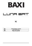
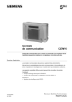
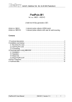
1.2
System overview
The OZW10 or OZW111 is the central unit on the M-bus. It communicates with the
consumption meters and controllers via M-bus:
• The OZW10 can be connected to a maximum of 750 M-bus devices and communicates with them via the RS-485 / M-bus signal converter WZC-P… With V4.0 or
higher, consumption meters of the Siemeca™ AMR system can also be integrated
via WTX16 or WTT16 radio nodes
• The OZW111 can be connected to a maximum of 5 M-bus devices and has an Mbus connection facility. Consumption meters of the Siemeca™ AMR system cannot
be connected
The M-bus central units can be connected to a PC or the ACS7… plant operating software, either directly or via modem.
ACS7…
ACS Operation
ACS Alarm
ACS Batchjob
ACS Alarm
OZW10
RS-485
WZC-P250
RS-485
OCI97
M-Bus
M-Bus
WZC-P60
OZW111
M-Bus
OZW10
OCI97
WTT16
WZC-R250
5361Z27
WTT16
7/90
Building Technologies
HVAC Products
M-bus System
1 System
CE1P5361en
08.02.2007
1.3
Use
The M-bus system is used for consumption cost billing and remote monitoring of
• community and district heating systems
• multifamily houses
Among other devices, the following types of units can be connected:
M-bus meters
• Heat meters SONOHEAT®, MEGATRON®2, SONOGYR® energy*, and
SONOGYR® WSD…*
• Water meters VOLUTRON®2
• Consumption meters via pulse adapter AEW21.2, Relay PadpulsM1
• Electronic heat cost allocators MEMOTRON®2 WHE21*
M-bus controllers
• District heating controllers SIGMAGYR® RVD2… (OZW10 V3.0 or higher, and
OZW111)
• District heating controllers SIGMAGYR® RVP97* (only with OZW10 of V3.0 or
higher)
Siemeca™ AMR
• Consumption meters of the Siemeca™ AMR system can be integrated via WTX16
or WTT16 radio nodes (only with OZW10 of V4.0 or higher):
®
− Heat meters MEGATRON 2
®
− Water meters VOLUTRON 2
®
− Heat cost allocators MEMOTRON 2 WHE26
− Consumption meters via pulse adapter AEW36.2
* Product no longer available, but still supported
1.4
Functions
The M-bus system offers a high level of safety in terms of data transmission and standard functionality while requiring only a minimum effort for engineering when setting up
the plant:
• Device identification via automatic search run
• Remote operation of plant with the PC, via modem or direct connection
• Acquisition of consumption data
• Remote readout of consumption data via memory card, via display on the M-bus
central unit, or with the PC
• Remote readout and setting the parameters of the control devices
• Visualization of plant diagrams
• Logging and graphic presentation of processes (Trend)
• Identification of device faults and malfunctions
• Delivery of alarms to the display of the M-bus central unit via alarm relay and to a
PC
• Status reports
• One-time or periodic execution of Batchjobs
8/90
Building Technologies
HVAC Products
M-bus System
1 System
CE1P5361en
08.02.2007
1.5
Documentation
Product
M-bus System – Fundamentals
Installation of Heating Plant in
compliance with EMC Directives
Plant Operating Software ACS7…
Plant Operating Software ACS700
Plant Operating Software ACS712
Plant Operating Software ACS713
Plant Operating Software ACS715
Plant Operating Software ACS741
Plant Operating Software ACS785
M-bus Central Unit OZW10
M-bus Central Unit OZW111
M-bus Signal Converter WZC-P250
M-bus Signal Converter WZC-P60
M-bus Repeater WZC-R250
Type of documentation
Data Sheet
Document no.
N5361
Data Sheet
Basic Documentation
Installation Instructions
User Manual
• ACS Operation
ACS Service
• ACS Alarm
• ACS Batchjob
Data Sheet
Data Sheet
Data Sheet
Data Sheet
Data Sheet
Data Sheet
Data Sheet
Mounting Instructions
User Manual
Popcards
Data Sheet
Installation Instructions
Data Sheet
Mounting Instructions
Data Sheet
Data Sheet
Mounting Instructions
N2034
P5640*
G5640
U5640
U5641
U5642
N5641
N5643
N5644
N5645
N5647
N5648
N5362
M2841
U5362
B5362
N5363
G5363
N5365
M5364
N5382
N5366
M5364
9/90
Building Technologies
HVAC Products
M-bus System
1 System
CE1P5361en
08.02.2007
2
System components
2.1
PC software ACS7…
2.1.1
Introduction
The ACS7… plant operating software is used for the remote operation and monitoring
of M-bus plant. Also, the M-bus central units are commissioned with the help of the
ACS7… plant operating software.
2.1.2
Use
The following versions of ACS7… are recommended for operating M-bus plant:
• ACS741: For the remote readout of meter consumption data
• ACS785: For the remote operation and monitoring of substations in district heating
networks with controllers and meters and for the remote readout of meter consumption data
The ACS7… package contains the following software programs:
ACS Operation
Software for the remote operation and monitoring of 1 or several plants equipped with
an OZW10 or OZW111 M-bus central unit.
ACS Alarm
Software for the reception of alarms and system reports from 1 or several central communication units OZW10 or OZW111.
ACS Batchjob
Software for the automatic control and logging of plant data of 1 or several district heating plants with OZW10 or OZW111.
ACS Service
Software for commissioning the OZW10 and OZW111 M-bus central units.
10/90
Building Technologies
HVAC Products
M-bus System
2 System components
CE1P5361en
08.02.2007
2.1.3
• User-defined
Popcard
• Standard
• User-defined
Trend
• Online
• Offline
File Transfer
Parameter Settings
Commissioning Report
Plant Navigation
• Device view
• Plant view
Connections
• Direct
• Modem
z
ACS785
z
ACS741
ACS715
• Standard
Visualization and remote operation of data points with graphic
display of plant
Predefined graph and data points
of each device
Graph, data points and interconnections as defined by the user
Visualization and remote operation
of all transmitted data points of the
connected devices
Predefined pages and data points
of each device
Pages and data points as defined
by the user
Acquisition and presentation of
the dynamic behavior of selected
data points
With connection to the plant
Without connection to the plant.
The Offline Trend function is not
provided by the OZW10 and
OZW111. This function is not
available with these central stations
Transmission and storage of files
of the central units and memory
cards.
The OZW111 does not store any
data, such as billing data. For this
reason, this function is only provided by the OZW10
Uploading and editing the setting
parameters of a device in tabular
form
Logging the setting values of individual devices, device groups, or
of the entire plant
Plant view in the form of a tree
structure
The view corresponds to the addressing of the devices
The view is determined by the
user
Type of connections
To the OZW10 and OZW111 via
standard null modem cable
Via telephone modems
ACS713
Plant Diagram
ACS712
The operating software provides a number of functions, depending on the type of selected software package.
Type of software
Function
Description
package
ACS700
Overview
Functions of ACS Operation
z
z
z
z
z
z
z
z
z
z
z
z
z
z
z
z
z
z
z
z
z
z
z
z
z
z
z
z
z
z
z
z
z
z
z
z
z
z
z
z
z
z
z
z
z
z
z
z
z
z
z
z
z
z
z
z
z
z
z
11/90
Building Technologies
HVAC Products
M-bus System
2 System components
CE1P5361en
08.02.2007
The operating software contains applications with the following features:
• The following applications can be started several times and run at the same time:
− Plant Diagram
− Popcard
− Online Trend
− Offline Trend
− File Transfer
− Parameter Settings
− Commissioning Report
• Several applications can be used simultaneously (e.g. Plant Diagram and Popcard)
• Active applications (e.g. Online Trend) can run in the background
• User-defined adaptations can be made in the following applications and views:
− Plant Diagram
− Popcard
− Plant view
The software contains a device description for each supported device. The device descriptions define
• the data points with the assigned properties
• the links to the applications
An overview of the data the ACS can access in the relevant devices is given in section
8.6 "Data of M-bus devices available on ACS7… ".
12/90
Building Technologies
HVAC Products
M-bus System
2 System components
CE1P5361en
08.02.2007
Plant Diagram
This application permits the graphic presentation of plant (individual devices or groups
of devices) with the following choices:
• Automatic updating of process values in the diagram
• Changing setpoints in the diagram
• In the case of user-defined diagrams, links to other diagrams can be established
A library with standard plant diagrams is assigned to each device type. For all supported plant diagrams, the library contains:
• The graphic presentation
• The data points to be displayed
• The text to be displayed
The application identifies the selected plant type, automatically assigns the standard
plant diagram and shows the current values.
A user-defined plant diagram can be generated for each device:
• By adopting and adjusting the standard plant diagram
• By creating a new plant diagram
A user-defined plant diagram is created as follows:
• Use external graphic software (e.g. Micrografx Picture Publisher™) for the graphic
presentation. The graphs can be adopted in Bitmap format
• For the inclusion of data points and links, the application has an Editor integrated
All user-defined plant diagrams will be stored in a separate library. They can also be
created without having a connection to the plant (offline).
Switching between the standard and the user-defined plant diagram is possible at any
time.
The plant diagrams can be printed out.
13/90
Building Technologies
HVAC Products
M-bus System
2 System components
CE1P5361en
08.02.2007
Popcard
This application is used to visualize the transmitted data points of each device and the
data points‘ values.
Each type of device uses standard popcards. Makeup and contents of the individual
pages are predefined.
User-defined popcards can be created for each device and each node. Data points of
all subordinate devices can be added to popcards that are assigned to a node. Standard and user-defined popcards can be copied to devices of the same type or to superposed nodes.
User-defined popcards offer the following features:
• They can consist of several user-defined pages
• Each page can be subdivided into several user-defined sections
• Freely selectable data points and separators can be assigned to the popcards, the
pages and the sections
Switching between the standard and the user-defined popcards is possible at any time.
Each selected page is automatically updated. The updating process will be visualized.
The operating pages can be printed out and exported as an ASCII file.
14/90
Building Technologies
HVAC Products
M-bus System
2 System components
CE1P5361en
08.02.2007
Trend
This application allows any data points of a plant to be logged.
The description, the selected data points of all devices of a plant and the sample interval are defined in the trend definition. With online trend, it is also possible to select
storage of the commissioning report at the start and end of the logging process. In offline trend, start and end of logging can be defined.
In trend logging, the cyclically queried data are stored and graphically presented. Earlier trend logging can be retrieved and presented again at any time.
With the OZW10 and OZW111, the Trend application is only available online:
• Online Trend: The connection between plant and PC is established. All acquired
data are stored directly on the PC. The graphic presentation of trend logging takes
place online
• Offline Trend: There is no connection between plant and PC. All acquired data will
be downloaded and stored on the memory card in the central unit. The graphic
presentation of logging is made after uploading
Trend logging can be printed out and exported as an ASCII file.
15/90
Building Technologies
HVAC Products
M-bus System
2 System components
CE1P5361en
08.02.2007
File Transfer
This application makes possible the exchange of data between the OZW10 and a PC in
M-bus plant. It enables
• files to be copied from the central unit or its memory card to the PC
• files to be copied from the PC to the central unit’s memory card
• memory cards to be formatted
Typically, the function is used with the OZW10 to upload billing data from the central
unit. For information about the data contained in a billing file, refer to subsection 8.5.5
"Data of M-bus devices stored in the billing file".
For visualizing the data, a selectable Editor suited for ASCII files can be started.
File transfer can be automated by making use of the Batchjob software.
The application is not available with the OZW111 since that central unit does not prepare billing data as a file. In plants equipped with the OZW111, the billing data can be
individually uploaded with the help of the ACS Batchjob software.
16/90
Building Technologies
HVAC Products
M-bus System
2 System components
CE1P5361en
08.02.2007
Parameter Settings
This application is used to downloaded, uploaded or compare the settings of the connected devices.
The settings can be
• stored as a parameter set
• compared with a stored parameter set
• compared with the standard parameter set
• overwritten with a stored parameter set
• overwritten with the parameter set
The parameter sets can be edited either online or offline. The individual data points of a
parameter set can be selected. The transmission result of uploading, downloading or
comparing is displayed online.
The parameter set can be printed out and exported as an ASCII file.
17/90
Building Technologies
HVAC Products
M-bus System
2 System components
CE1P5361en
08.02.2007
Commissioning Report
This application is used to log the setting values of individual devices, groups of selected devices or of entire plants.
The data points of the selected devices are stored with data point designation, value,
unit and state.
The commissioning report can be printed out and exported as an ASCII file.
2.1.4
Overview
Functions of ACS Alarm
Alarm software is a superposed program contained in all types of software packages.
Function
Alarm
System Report
Connections
Description
Alarms from the central unit or the plant are received, stored,
indicated and output on a printer
Information from the central unit or the plant is received, stored,
indicated and output on a printer
Type of connections
18/90
Building Technologies
HVAC Products
M-bus System
2 System components
CE1P5361en
08.02.2007
Function
• Direct
• Modem
Description
On the OZW10 and OZW111, with standard null modem cable
Via telephone modems
The alarm software contains the following applications for the reception and further
handling of alarms and of the plant’s state:
• Alarm
• System Report
Alarm
System Report
Alarm
Every alarm received from the plant is entered in an alarm list.
The process that takes place after reception of an alarm can be configured:
• Audible signal
• A popup window opens. The alarm is entered in the alarm list only when the window is closed
• Output on a printer
• Any combination of the 3 choices
19/90
Building Technologies
HVAC Products
M-bus System
2 System components
CE1P5361en
08.02.2007
The user can select the columns of the alarm list. The column designations and the arrangement of the individual columns can be configured on a user-specific basis.
The entire alarm list can be exported as an ASCII file. Also, to facilitate further handling in
other programs, the alarms received are automatically exported to an ASCII file.
An overview of the possible alarms from the OZW10 and OZW111 is given in section 8.7
"Error messages from M-bus devices and alarm messages delivered by the OZW…".
System Report
The system report is used to monitor plant operation.
It contains general information about the plant, such as type of central unit, phone
number of the plant, and plant name.
The system report can be output on a local printer.
20/90
Building Technologies
HVAC Products
M-bus System
2 System components
CE1P5361en
08.02.2007
2.1.5
The Batchjob software is a superposed program that is available depending on the type
of selected software package.
Definition, planning and evaluation of
Planning and
Evaluation of Task tasks
ACS785
ACS741
Monitoring of all planned tasks
ACS715
Execution of Task
Software package
ACS713
Description
ACS712
Function
ACS700
Overview
Functions of ACS Batchjob
z
z
z
z
Logging of Task
Recording of results of execution of all
planned tasks
z
z
Plant Navigation
View of plants in a tree structure
z
z
Connections
• Direct
Type of connections
z
z
z
z
• Modem
To the OZW10 and OZW111 with standard null modem cable
Via telephone modems
The Batchjob software contains applications for automatic control and recording of
plant data:
• Execution of Task
• Planning and Evaluation of Task
• Logging of Task
Execution of Task
Execution of task allows all plants to be monitored. The tasks can be executed on different types of plant. Tasks include one-time or periodic uploading and downloading of
data points and uploading files.
The execution of tasks can be generally started or stopped. Individual tasks can be
enabled or disabled. A task can immediately be executed.
The task state and the result of the last execution are visualized with a symbol.
Planning and Evaluation
of Task
This application is used for planning tasks and for their evaluation.
Planning and evaluation of a task comprises a description, the time of execution, and a
number of instructions. Execution can take place once at a certain time, or periodically.
Instructions include downloading and uploading data points and uploading files. The
result of the task can automatically be exported.
A task is always confined to one plant.
21/90
Building Technologies
HVAC Products
M-bus System
2 System components
CE1P5361en
08.02.2007
Logging of Task
This application logs the processes taking place when a task is executed. All tasks are
included, irrespective of automatic or manual execution.
22/90
Building Technologies
HVAC Products
M-bus System
2 System components
CE1P5361en
08.02.2007
2.1.6
Functions of ACS Service
The ACS service software has a fixed functionality and is included in all software packages.
Function
Popcard
Description
Visualization and remote operation of all data points transmitted
by the connected devices
• Standard
• User-defined
Online Trend
Pages and data points predefined for each device
Pages and data points as defined by the user
Acquisition and presentation of dynamic behavior of selected
data points, with connection to the plant
Parameter Settings
Uploading and editing the setting parameters of a device in tabular form
Commissioning
Report
Logging the setting values of individual devices, device groups,
or of the entire plant
Plant Navigation
View of plant as a tree structure. The makeup of the tree structure corresponds to device addressing
Connection
Directly to the OZW10 or OZW111 via standard modem cable
For a detailed description of the applications, refer to subsection 2.1.3 "Functions of
ACS Operation".
2.1.7
Plant navigation
To facilitate plant navigation, the plant is presented in the form of a tree structure. This
view is supported by the following applications:
• Plant Diagram
• Popcard
• Online Trend
• Offline Trend
• Parameter Settings
• Commissioning Report
• Planning and Evaluation of Task
• Logging of Task
The following views can be selected:
• Device view
• Plant view
Device view
Generation of “Plant view”
23/90
Building Technologies
HVAC Products
M-bus System
2 System components
CE1P5361en
08.02.2007
The device view shows the plant in accordance with device addressing.
In the plant view, the tree structure can be defined on a user-specific basis. The tree
structure is defined by including nodes. The devices can be assigned to the nodes as
required.
• Switching between device view and plant view is possible at any time. A description can be added to each device and each node
• The plant view in the form of a tree structure can either be shown or hidden
2.1.8
Communication
For detailed information about the communication between ACS… and OZW…, refer to
section 6.1 "Communication between ACS7… and OZW…".
Direct connection
The direct connection necessitates a standard null modem cable between M-bus central unit and PC.
Telephone connection
When using the connection via the telephone network, a Hayes-compatible modem is
required on each side.
2.1.9
The functions described in sections
• 2.1.3 "Functions of ACS Operation"
• 2.1.4 "Functions of ACS Alarm"
• 2.1.5 "Functions of ACS Batchjob"
• 2.1.6 "Functions of ACS Service"
depend on the type of central unit and the service interface used:
Type of central unit / service interface
OCI611
OZW10 3)
OZW111
OCI69
OCI700
z
z
z
z
z
z
z
z
z
z
z
z
z
z
z
z
z
z
z
z
z
z
z
z
z
z
z
z
z
z
z
z
z
z
z
z
z
z
z
z
z
z
z
z
z
z
z
z
z
z
z
z
z
z
z
z
z
z
z
z
z
z
z
z
z
z
z
OCI55
OCI600
Plant Diagram
Popcard
Trend
• Online
• Offline
File Transfer
Parameter Settings
Commissioning Report
Plant Navigation
Alarm
System Report
Execution of Task
Planning and Evaluation of Task
Logging of Task
Connections
• Direct
• Modem
OZW771
Function
OZW30
Functions in connection
with the central units
Equipment combinations
z
z
z
z
z
z
z
z
z
z
z
z
z
z 1) z 1) z 1) z 1) z 1) z 1) z 1) z 1) z 2)
z
z
z
z
z
z
z
1) With standard null modem cable
2) With standard USB cable (connector type A to B)
3) V3.0 or higher
For more information about the central units, refer to sections 2.2 "M-bus central unit
OZW10" and 2.3 "M-bus central unit OZW111".
24/90
Building Technologies
HVAC Products
M-bus System
2 System components
CE1P5361en
08.02.2007
Number of plants
The number of plants is unlimited for all programs (ACS Operation, ACS Alarm, ACS
Batchjob and ACS Service). In the ACS programs, a plant is created for each central
unit.
Functions in connection
with M-bus devices
In the ACS7… programs, data of all types of M-bus devices can be displayed and
downloaded. The data originate either directly from the M-bus device or from the central unit, depending on the type of central unit used:
• The OZW10 uploads certain data of the M-bus devices cyclically and stores them.
In the case of plants equipped with the OZW10, the data can either be uploaded directly from the M-bus device or from the memory of the central unit using the ACS…
The kind of data stored in the OZW10 depends on the type of M-bus device. An
overview is given in subsection 2.2.5 "Equipment combinations"
• The OZW111 does not store any data from the M-bus devices. ACS7… always
uploads the data ("transparently") from the M-bus device
For the kind of data of the respective M-bus device available on ACS7…, refer to section 8.6 "Data of M-bus devices available on ACS7… ".
Number of devices
per plant
With the operating software and the Batchjob software, the number of devices per plant
are limited. By contrast, with the alarm software and the service software, the number
of devices are unlimited. For limiting the number of devices, a credit is defined for each
standard package. Every connected device of the plant charges this credit with a device-specific value. The number of devices that can be served is limited by the credit
amount available. Additional credits can be ordered separately:
Software
Operating software
Batchjob software
Credit per software package
ACS700
200
ACS712
200
ACS713
200
ACS715
200
200
ACS741
1300
ACS785
3900
3900
Type of product
Device-specific credit
OCI600, OCI611, OZW10, OZW111, OZW771, OZW775
OCI69, OCI700, WTX16, WTT16, KNX line coupler
Synco™ RMU7…, RMH7…, RMB7…, RMK7…, RMS7…
Synco™ RLU2…, SEZ2…
Synco™ RXB…*
Synco™ QAW740
SIGMAGYR® RVL…, RVP…, RVD…
SONOHEAT®, SONOGYR®
Siemeca™ WF.21…, WF.26…
Siemeca™ WHE21…, WHE36
Siemeca™ AEW21.2 and AEW36.2 per input
PadpulsM1
Third-party device with own Device Description
Unknown device without own Device Description
10
0
8
8
2
1
8
3
2
1
1
1
8
8
* only RXB… with KNX logo
PC hardware
PC component
Processor
RAM
Hard disk
Screen
Minimum requirement
Pentium-compatible
300 MHz, recommended 600 MHz
128 MB, recommended 256 MB
1.9 GB free memory (Windows XP)
2.0 GB with 1.0 GB free memory (Windows 2000)
Recommended: additional 20 MB free memory per plant
VGA standard driver 800 × 600, 256 colors
Recommended: SVGA standard driver 1028 × 768
25/90
Building Technologies
HVAC Products
M-bus System
2 System components
CE1P5361en
08.02.2007
PC component
Ports
Operating system
Diskette drive
CD-ROM or DVD drive
Minimum requirement
USB 1.1 and higher
Serial COM up to 19,200 Baud (directly or via modem)
Windows XP, service pack 1
Windows 2000, service pack 3
3½”, 1.44 MB, for diskette with log file
PC software
To further handle exported data, a user program, such as Microsoft® Excel, is required.
It must be suited for ASCII files
• that consist of several lines and columns, and
• whose columns are separated by tabs
Modems
Modems are required if communication takes place via the telephone network. The
drivers of the modems installed under Windows can be used.
2.1.10 Dongle
The dongle is the same as that used with DESIGO® Insight. Each dongle carries a serial number.
Copy protection
USB dongle
Type reference
CMD.02
Standard packages are supplied complete. If required, they contain the CMD.02 dongle
and the license file (diskette). The license is required to enable the functions in the individual software programs.
The following standard packages are available:
Type reference
Dongle CMD.02
ACS700
–
ACS712
Contained
ACS713
Contained
ACS715
Contained
ACS741
Contained
ACS785
Contained
Extra packages are available for extending the functions of the standard packages.
Based on the ACS700 standard package, a CMD.02 dongle is required. For more information about the extra packages, refer to Data Sheet N5640 (ACS7…).
2.2
M-bus central unit OZW10
2.2.1
Introduction
The M-bus central unit is used for the remote readout, remote operation and monitoring of
M-bus plant with consumption meters and controllers having an M-bus connection facility
conforming to EN 1434-3 and of consumption meters of the Siemeca™ AMR system.
2.2.2
Use
The M-bus central unit is designed for consumption cost billing and remote monitoring
of district heat systems and multifamily houses.
Among other devices, the following types of M-bus devices can be connected:
M-bus meters
• Heat meters SONOHEAT®, MEGATRON®2, SONOGYR® energy*,
SONOGYR® WSD…*
26/90
Building Technologies
HVAC Products
M-bus System
2 System components
CE1P5361en
08.02.2007
• Consumption meters via pulse adapter AEW21.2, Relay PadpulsM1
• Heat cost allocators MEMOTRON®2 WHE2*
M-bus controllers
• District heating controllers SIGMAGYR® RVD2…
• District heating controllers RVP97*
Siemeca™ AMR
Consumption meters of the Siemeca™ AMR system can be integrated via WTX16 or
WTT16 radio nodes (V4.0 or higher):
• Heat meters MEGATRON®2
• Water meters VOLUTRON®2
• Heat cost allocators MEMOTRON®2 WHE26
• Consumption meters via pulse adapter AEW36.2
Other devices on request.
* Product no longer available, but still supported
2.2.3
Functions
The M-bus central unit
• identifies connected M-bus and Siemeca™ AMR devices with the help of its automatic search run: For detailed information, refer to section 8.3 “Search run of central units OZW10 and OZW111".
• acquires and stores the consumption data of the M-bus and Siemeca™ AMR devices at regular intervals
• displays the stored consumption data
• copies the stored consumption data to a billing file of the memory card at the press
of a button
• makes possible to access
− stored consumption data
− the memory card
− directly the M-bus devices by means of a PC connected either directly or via modem (V3.0 or higher)
• monitors periodically the M-bus and Siemeca™ AMR devices and 4 potential-free
digital inputs
• indicates alarms
− on the display
− via alarm relay
− to a PC, either directly or via modem (V3.0 or higher)
Parameter settings
The M-bus central unit can be parameterized in 2 different ways:
• Via the buttons of the M-bus central unit
• With a PC, connected directly or via modem, with the help of the ACS service software (only directly) or the ACS operating software (directly or via modem)
Setup
On request, the M-bus central unit automatically searches for the M-bus and Siemeca™ AMR devices used by the system. Supported are primary and secondary addressing (type of addressing on the M-bus) and the Baud rates 300, 2,400 and 9,600
Baud (Baud rates on the M-bus). The type of addressing and the Baud rates can be
selected.
27/90
Building Technologies
HVAC Products
M-bus System
2 System components
CE1P5361en
08.02.2007
The device list is stored in nonvolatile memory.
For detailed information about the search run, refer to section 8.3 "Search run of central
units OZW10 and OZW111".
Readout
The M-bus central unit offers a number of choices for reading the M-bus and Siemeca™ AMR devices. It must be appropriately parameterized:
• Readout cycle with manual querying: The data are read out via M-bus only when
requested
• Readout cycle with periodic querying: The data are periodically and automatically
read out – hourly, daily, weekly or monthly. It should be noted however that in the
case of battery-powered M-bus devices, frequent readout can shorten the batteries‘ life, depending on the type of device (e.g. SONOGYR® and MEGATRON®, but
not SONOHEAT® 2WR4 and 2WR5). If such devices are used by the system, no
more than 1 reading per day is normally permitted. For details, refer to the specification of the relevant product
• Alarm cycle (V3.0 or higher): For monitoring, controllers can be queried more frequently. The alarm cycle can be set at increments of minutes
All data known to the M-bus central unit are stored in an internal process image and
prepared for further handling. Siemeca™ AMR devices send their data periodically to
the radio nodes WTX16 or WTT16. The OZW10 uploads the data stored in the radio
nodes.
Evaluating the
consumption data
The M-bus central unit stores the data of all M-bus and Siemeca™ AMR devices last
read. They can be read out at the M-bus central unit. To handle them on a PC, the data
can be transferred as follows:
• The data are made available via the RS-232 port as a billing file. They can then be
read out with the help of the ACS7… PC software, either directly or via modem
• The data are transferred to a memory card in the form of a billing file. The M-bus
central unit has a slot to insert the memory card. The memory card is forwarded to
the billing agency, which loads the data directly to the PC via the RS-232 port using a second M-bus central unit OZW10 and the ACS7… PC software
For a description of the billing file, refer to section 8.5 "Billing file".
28/90
Building Technologies
HVAC Products
M-bus System
2 System components
CE1P5361en
08.02.2007
Digital inputs
Alarms
The M-bus central unit has 4 digital inputs for the connection of potential-free contacts.
When a contact closes, the M-bus central unit indicates an alarm.
The M-bus central unit identifies the following types of faults:
• Signals at the digital inputs: Immediate delivery of alarm messages
• Failures of M-bus and Siemeca™ AMR devices: Cyclic readout of data by the central unit, depending on the setting made (refer to "Readout": Readout interval,
alarm interval). Failure of a device is signaled as an alarm only after the central
unit has failed to make a readout
• Error messages from the M-bus and Siemeca™ AMR devices: Since the M-bus is
a single master slave bus, the devices cannot by themselves send the fault status
messages to the central unit. Therefore, the central unit needs to cyclically query
the devices one by one. This query is made during readout, depending on the setting made (refer to "Readout": Readout interval, alarm interval). A fault detected at
a device is signaled as an alarm only after the central unit has completed its readout.
Siemeca™ AMR devices send their data periodically to the radio nodes WTX16 or
WTT16. Only when the faults have been transmitted to the radio node can they be
read out by the M-bus central unit via radio node
• Faulty memory card, insufficient battery voltage, etc.: Immediate delivery of alarms
• Device error of the M-bus central unit: Immediate delivery of alarms
• A description of all faults that can be detected by the M-bus central unit is given in
section 8.7 "Error messages from M-bus devices and alarm messages delivered by
the OZW…".
The faults can be weighted and assigned to the following types of output devices:
• Indication of alarms
• Alarm relay
• PC with alarm software "ACS Alarm"
Each error code of the central unit can be assigned a priority (e.g. error code "01 Tv<Tr
or T outside value range" of the central unit in the above example has priority 0 as the
standard setting). Errors having priority 0 are not passed on to any output device. Errors having priority 1 through 3 are passed on to the output devices, depending on the
setting made.
A description of all faults that can be detected by the M-bus central unit is given in section 8.7 "Error messages from M-bus devices and alarm messages delivered by the
OZW…".
Faults that have occurred are displayed by the OZW… until rectified and acknowledged. Acknowledgement is made by pressing the buttons or by routing the alarm to
the PC.
Rectification of faults is not signaled to the control center.
29/90
Building Technologies
HVAC Products
M-bus System
2 System components
CE1P5361en
08.02.2007
2.2.4
Communication
For detailed information about communication between ACS… and OZW…, refer to
section 6.1 "Communication between ACS7… and OZW…".
Direct connection
In the case of a direct connection, a standard null modem cable is required between Mbus central unit and PC.
Telephone connection
In the case of a connection via the telephone network, a Hayes-compatible modem is
required on each side.
2.2.5
Signal converter
Equipment combinations
The M-bus central unit has an RS-485 port. To be able to connect the central unit to the
M-bus devices, an external signal converter is required. It must be connected to the
RS-485 port of the central unit:
• WZC-P250 (Data Sheet N5365) for 250 M-bus devices, can be combined with repeaters WZC-R250 (Data Sheet N5366), or
• WZC-P60 (Data Sheet N5382) for a maximum of 60 M-bus devices (V3.0 or
higher)
Type of device
Maximum
number
1
1
M-bus central unit
M-bus signal converter for a maximum of 250
devices, or
M-bus signal converter for a maximum of 60
1
devices
M-bus repeater for a maximum of 250 devices Unlimited 1)
M-bus devices
750 2)
Type
reference
OZW10
WZC-P250
Data
Sheet
N5362
N5365
WZC-P60
N5382
WZC-R250
N5366
1) In combination with the WZC-P250. For more information, refer to chapter 5 "Engineering"
2) The number of M-bus devices in dependent on the number of device types connected. For information
about calculation, refer to chapter 5 "Engineering"
For more information about the signal converters, refer to sections 2.4 "M-bus signal
converter WZC-P250" and 2.5 "M-bus signal converter WZC-P60".
Functions in connection
with M-bus devices
The M-bus central unit reads certain data cyclically from the connected M-bus and
Siemeca™ AMR devices and stores them until the next readout is made. Depending on
the type of device, the OZW10 makes other data available. A description of these data
is given in section 8.5 "Billing file".
Accessories
If readout of the consumption data is not made via RS-232 port or modem, it can also
be made via memory card:
Type of memory card
Type reference
ALC30.128
Memory card 128 KB
ALC30.512
Memory card 512 KB
The M-bus central unit is operated on site with the help of the ARG10.DE operating set,
which consists of:
Type of document
Document no.
Operating Manual
U5362
Popcards
B5362
30/90
Building Technologies
HVAC Products
M-bus System
2 System components
CE1P5361en
08.02.2007
2.2.6
Spare parts
For upgrading the OZW10, the most recent software version can be ordered as a separate item:
Product
Part number
74 340 0002 0
Program memory OZW10
It is always the most recent version that is supplied. When ordering the above part
number, 16 pairs of OTP will be supplied. Smaller quantities cannot unfortunately be
provided.
To change the OTPs, proceed as follows:
1. Save the billing file.
2. Open the OZW10 (screw on the front of the unit at bottom right).
3. Disconnect power supply to the OZW10 (terminal strip on the right).
4. Remove the OTPs (labeling: OZW10 Vx.y date A/B) with a suitable tool (pair of IC
or PLCC pliers).
5. Fit the new OTPs: A on the right, B on the left.
Ensure that the beveled edge of the OTPs is at top right.
6. Connect power supply again.
7. Acknowledge error message "Error 12" by pressing the button.
Check if the plant is still stored in the list. If not, recreate the device list (page 4, line 47).
2.3
M-bus central unit OZW111
2.3.1
Introduction
The M-bus central unit is used for the remote readout, remote operation and monitoring
of M-bus plant with a maximum of 5 consumption meters and controllers having an Mbus connection facility conforming to EN 1434-3.
2.3.2
Use
The M-bus central unit is designed for remote monitoring of district heating systems
and for consumption cost billing in multifamily houses.
Among others, the following types of M-bus devices can be connected:
M-bus meters
• Heat meters SONOHEAT®, MEGATRON®2, SONOGYR® energy*,
SONOGYR® WSD…*
• Consumption meters via pulse adapter AEW21.2, Relay PadpulsM1
• Heat cost allocators MEMOTRON®2 WHE21*
M-bus controllers
• District heating controllers SIGMAGYR® RVD2…
Not supported are the following types of devices:
• District heating controllers SIGMAGYR® RVP97
• Consumption meters of the Siemeca™ AMR system
Other M-bus devices on request.
* Product no longer available, but still supported
31/90
Building Technologies
HVAC Products
M-bus System
2 System components
CE1P5361en
08.02.2007
2.3.3
Functions
The M-bus central unit
• identifies the connected M-bus devices via its automatic search run (for detailed
information, refer to section 8.3 "Search run of central units OZW10 and OZW111")
• makes possible the direct access to the M-bus devices via a PC, connected either
directly or via modem
• monitors periodically the M-bus devices and 2 potential-free digital inputs
• delivers alarms to a PC, either directly or via modem
• provides a clock function for alarms
Parameter settings
The parameters of the M-bus central unit are set with the help of a PC, connected either directly or via modem and using ACS Service (only directly) or ACS Operation
(directly or via modem).
Acquisition of M-bus
devices
Upon request, the M-bus central unit automatically searches for the M-bus devices
used by the system. Supported are primary and secondary addressing (type of addressing on the M-bus) and Baud rates of 300 and 2,400 (Baud rates on the M-bus).
The type of addressing and the Baud rate can be selected:
The device list is stored in nonvolatile memory.
Detailed information about the search run is given in section 8.3 "Search run of central
units OZW10 and OZW111".
Querying the M-bus
devices
Evaluating
consumption data
The M-bus central unit offers a number of choices for querying the M-bus devices:
• Readout cycle with manual querying: The data are queried via M-bus only when
requested
• Readout cycle with periodic querying: To ensure monitoring of the devices, the
data are periodically and automatically queried – hourly, daily, weekly or monthly.
It should be noted however that in the case of battery-powered M-bus devices, frequent readout can shorten the batteries‘ life, depending on the type of device (e.g.
SONOGYR® and MEGATRON®, but not SONOHEAT® 2WR4 and 2WR5). If such
devices are used by the system, no more than 1 reading per day is normally permitted. For details, refer to the specification of the relevant product
• Alarm cycle: For monitoring, controllers can be queried more frequently. The alarm
cycle can be set at increments of minutes
The data are made available via the RS-232 port, where they can be read out with the
help of the appropriate PC software, either directly or via modem. More information
about the available data is given in section 8.6 "Data of M-bus devices available on
ACS7… ".
If a billing file is required,
• the data can be cyclically read out with the help of ACS Batchjob and stored in a file
• the OZW10 M-bus central unit can be used
32/90
Building Technologies
HVAC Products
M-bus System
2 System components
CE1P5361en
08.02.2007
Digital inputs
The M-bus central unit has 2 digital inputs for the connection of potential-free contacts.
The operating action of the contacts (active closed or active open) can be parameterized.
Alarms
The M-bus central unit can detect the following types of fault:
• Messages delivered to the digital inputs: Immediate delivery of alarms
• Failures of M-bus devices: Cyclic readout of device data by the central unit, depending on the setting made (refer to "Readout": Readout interval, alarm interval).
Failure of an M-bus device is signaled as an alarm only after the central unit has
failed to make a readout
• Error messages from the M-bus devices: Since the M-bus is a single master slave
bus, the M-bus devices cannot by themselves send the fault status messages to
the central unit. Therefore, the central unit needs to cyclically query the devices
one by one. This query is made during readout, depending on the setting made
(refer to "Readout": readout interval, alarm interval).
A fault detected at an M-bus device is signaled as an alarm only after the central
unit has completed its readout
• Device error of the M-bus central unit: Immediate delivery of alarms
The faults can be weighted and assigned to the following types of output devices:
• Alarm LED
• PC with alarm software "ACS Alarm"
Each error code of the central unit can be assigned a priority (e.g. error code "01 Tv<Tr
or T outside value range" of the central unit in the above example has priority 0 as the
standard setting). Errors having priority 0 are not passed on to any output device. Errors having priority 1 through 3 are passed on to the output devices, depending on the
setting made.
A description of all faults that can be detected by the M-bus central unit is given in section 8.7 "Error messages from M-bus devices and alarm messages delivered by the
OZW…".
Rectification of a fault is not signaled to the control center.
33/90
Building Technologies
HVAC Products
M-bus System
2 System components
CE1P5361en
08.02.2007
2.3.4
Communication
For detailed information about the communication between ACS… and OZW…, refer to
section 6.1 "Communication between ACS7… and OZW…".
Direct connection
In the case of a direct connection, a null modem is required between M-bus central unit
and PC.
Telephone connection
In the case of a connection via the telephone network, a Hayes-compatible modem is
required on each side.
2.3.5
Equipment combinations
The OZW111 has its M-bus power supply integrated and requires no additional M-bus
signal converter. A maximum of 5 M-bus devices can be connected to the M-bus central unit.
M-bus mini plant
M-bus central unit
M-bus devices
Note
Maximum
number
1
5*
Type
reference
OZW111
Data Sheet
N5363
* The SONOHEAT® heat meters with an M-bus module up to V1.06 produce a bus load
of 1.5 standard loads. For this reason, this type of meter produces a load of 1.5 M-bus
devices on the M-bus. Hence, a maximum of 5/1.5 = 3 SONOHEAT® heat meters with
an M-bus module up to V1.06 can be connected to an OZW111.
All other devices and SONOHEAT® heat meters with an M-bus module of V2.01 or
higher represent 1 M-bus standard load.
2.4
M-bus signal converter WZC-P250
2.4.1
Introduction
The M-bus signal converter converts RS-485 signals to M-bus signals.
2.4.2
Use
The M-bus signal converter serves for the connection of an M-bus central unit with an
RS-485 port to the M-bus.
2.4.3
Functions
The M-bus signal converter
• converts the RS-485 signals to M-bus signals
• operates as a bus driver.
2.4.4
Equipment combinations
The M-bus signal converter is for connection to the RS-485 port of the OZW10 (refer to
section 2.2 "M-bus central unit OZW10").
A maximum of 250 M-bus devices can be connected to the M-bus signal converter.
34/90
Building Technologies
HVAC Products
M-bus System
2 System components
CE1P5361en
08.02.2007
M-bus segment
M-bus signal converter for a maximum of
250 devices
M-bus devices
Note
Maximum
number
1
Type
reference
WZC-P250
Data Sheet
N5365
250*
* The SONOHEAT® heat meters with an M-bus module up to V1.06 produce a bus load
of 1.5 standard loads. For this reason, this type of meter produces a load of 1.5 Mbus devices on the M-bus. Hence, a maximum of 250/1.5 = 166 SONOHEAT® heat
meters with an M-bus module up to V1.06 can be connected to a WZC-P250.
All other devices and SONOHEAT® heat meters with an M-bus module of V2.01 or
higher represent 1 M-bus standard load.
2.5
M-bus signal converter WZC-P60
2.5.1
Introduction
The M-bus signal converter converts RS-485 signals to M-bus signals.
2.5.2
Use
The M-bus signal converter serves for the connection of an M-bus central unit with an
RS-485 port to the M-bus.
2.5.3
Functions
The M-bus signal converter
• converts RS-485, RS-232 or optical signals to M-bus signals
• operates as a bus driver
2.5.4
Equipment combinations
In the M-bus system, the M-bus signal converter is for connection to the RS-485 port of
the M-bus central unit.
A maximum of 60 M-bus devices can be connected to the converter.
M-bus segment
Maximum
number
M-bus signal converter for max. 60 devices 1
M-bus devices
60*
Note
Type
reference
WZC-P60
Data Sheet
N5382
* The SONOHEAT® heat meters with an M-bus module of V1.06 or higher produce a
bus load of 1.5 standard loads. A SONOHEAT® heat meter with an M-bus module up
to V1.06 corresponds to 1.5 devices: This means that a maximum of 60/1.5 = 40
SONOHEAT® heat meters with an M-bus module up to V1.06 can be connected to a
WZC-P60.
All other devices and SONOHEAT® heat meters with an M-bus module of V2.01 or
higher represent 1 M-bus load.
35/90
Building Technologies
HVAC Products
M-bus System
2 System components
CE1P5361en
08.02.2007
2.6
M-bus repeater WZC-R250
2.6.1
Introduction
The M-bus repeater is an amplifier for use in M-bus plants where long bus distances
must be covered.
2.6.2
Use
The M-bus repeater is for use in plants where extensive bus lines are required, or
where a large number of devices need to be connected, e.g. in district heating plants
that supply heat to entire sections of towns.
2.6.3
Functions
The M-bus repeater
• operates as a signal amplifier
• enables plant to be subdivided into several M-bus sections
2.6.4
Equipment combinations
Through the use of M-bus repeaters (connected in series or in parallel), the plant can
be subdivided into several M-bus segments.
A maximum of 250 M-bus devices can be connected to the M-bus repeater.
M-bus segment
M-bus repeater for maximum 250 devices
M-bus devices
Maximum
number
11)
250 2)
Type
Data Sheet
reference
WZC-P250 N5366
1) This limitation applies to the M-bus output (master)
Note
2) The SONOHEAT® heat meters with an M-bus module of V1.06 or higher produce a
bus load of 1.5 standard loads. A SONOHEAT® heat meter with an M-bus module
up to V1.06 corresponds to 1.5 devices: This means that a maximum of 250/1.5 =
1660 SONOHEAT® heat meters with an M-bus module up to V1.06 can be connected to a WZC-P60.
All other devices and SONOHEAT® heat meters with an M-bus module of V2.01 or
higher represent 1 M-bus load.
36/90
Building Technologies
HVAC Products
M-bus System
2 System components
CE1P5361en
08.02.2007
3
M-bus devices and Siemeca™ AMR
3.1
Controllers with M-bus
3.1.1
Introduction
In district heating systems, the substations for remote operation and monitoring are
interconnected across long distances. For that purpose, the
• district heating controllers SIGMAGYR® RVD2…
• district heating controllers SIGMAGYR® RVP97 (via OCI97 bus interface)
are equipped with an M-bus interface. This enables the district heating controllers to be
used with any type of M-bus meters on the same bus.
Detailed information about the individual controllers is given in the relevant pieces of
documentation:
Type reference
RVD230
RVD240
RVP97*
OCI97*
Data Sheet
N2383
N2384
N2406
N2901
Basic Documentation
P2383
P2384
P2406
–
* Product no longer available, but still supported
3.1.2
Use
The table below shows the use of the district heating controllers in the M-bus system:
Type of
controller
M-bus connection
facility
RVD23…
M-bus connection
facility integrated
in the controller
RVD24…
M-bus connection
facility integrated
in the controller
RVP97
Integrated via bus
interface OCI97
3.1.3
Control function
Precontrol
Primary controller for
district heat substations
with interconnected system (plant types 5–x,
6–x, 7–2)
Heat distribution heating
circuit, DHW
Controller for district heat
substation with heating
circuit and DHW heating
(plant types 0–x, 1–x, 2–x,
3–x, 8–4)
Controller for district heat
substation with 2 heating
circuits and DHW heating
(all plant types 1–x, 2–x,
3–x, 4–x)
Controller for district heat
substation with heating
circuit and DHW heating
Functions
Detailed information about the functions of the individual controllers is given in the relevant pieces of documentation.
The district heating controllers make possible remote operation and monitoring of all
key data via the M-bus interface. The operating software "ACS Operation" has the data
grouped in accordance with its use. The grouping corresponds to the makeup of the
popcards.
37/90
Building Technologies
HVAC Products
M-bus System
3 M-bus devices and Siemeca™ AMR
CE1P5361en
08.02.2007
Popcards RVD2…
No
1
2
3
4
5
6
7
8
9
10
11
12
13
14
15
Data group (operating page) Description
Overview
Overview of the plant’s state (faults, limitations,
operating state, process data, setpoints, actual
values, etc.)
Status and errors
Operating modes, fault indication, indication of
limitations
Converter
Overview of the setting parameters, plant state,
setpoints and actual values related to the primary control loop (converter)
Heating circuit 1
Overview of the setting parameters, plant state,
setpoints and actual values related to heating
circuit 1
Heating circuit 2 (RVD24…) Overview of the setting parameters, plant state,
setpoints and actual values related to heating
circuit 2
DHW
Overview of the setting parameters, plant state,
setpoints and actual values related to DHW
heating
Setpoints
Overview of all plant and setting values
IOs
Overview of all input and output signals
Connection conditions
Overview of all district heat-specific settings and
limit values
Load management
Parameter for influencing the space and DHW
heating load
Switching programs
Settings for the switching program of heating
(RVD23…)
circuit 1
Time program 1 (RVD24…)
Time program 2 (RVD24…) Settings for the switching program of heating
circuit 2
Time program DHW
Settings for the switching program for DHW
heating or for the circulating pump
Global configuration
Overview of the configuration parameters
Device identification
Device-specific information
For more information, refer to the following sections:
8.6 "Data of M-bus devices available on ACS7… "
8.5.5 "Data of M-bus devices stored in the billing file"
8.7 "Error messages from M-bus devices and alarm messages delivered by the
OZW…".
Popcards RVP97
No
1
2
3
4
Data group (operating page) Description
Overview
Overview of the plant’s state (faults, limitations,
operating state, process data, setpoints, actual
values, etc.)
Status and errors
Operating modes, fault indication, indication of
limitations
Precontrol
Overview of the setting parameters, plant state,
setpoints and actual values related to the primary control loop
Heating circuit 1
Overview of the setting parameters, plant state,
setpoints and actual values related to heating
circuit 1
38/90
Building Technologies
HVAC Products
M-bus System
3 M-bus devices and Siemeca™ AMR
CE1P5361en
08.02.2007
No
5
6
7
8
9
11
12
13
14
Data group (operating page) Description
Heating circuit 2
Overview of the setting parameters, plant state,
setpoints and actual values related to heating
circuit 2
DHW
Overview of the setting parameters, plant state,
setpoints and actual values related to DHW
heating
Setpoints
Overview of all plant values and setpoints
IOs
Overview of all input and output signals
Connection conditions
Overview of all district heat-specific settings and
limit values
Switching programs heating Settings for the switching program of heating
circuit 1
circuit 1
Switching programs heating Settings for the switching program of heating
circuit 2
circuit 2
Global configuration
Overview of the configuration parameters
Device info
Device-specific information
For more information, refer to the following sections:
8.6 "Data of M-bus devices available on ACS7… "
8.5.5 "Data of M-bus devices stored in the billing file"
8.7 "Error messages from M-bus devices and alarm messages delivered by the
OZW…".
3.1.4
Equipment combinations
Within an M-bus system, the district heating controllers can be arbitrarily interconnected
or connected to other M-bus-compatible devices.
Only the district heating controllers RVD2… of V2.1 or higher can be used in M-bus
systems. RVD2… of versions lower than 2.1 do not ensure trouble-free operation on
the M-bus and, for this reason, may only be used in special circumstances. Additional
information is provided on request.
3.2
M-bus meters
3.2.1
Introduction
For electronic consumption cost billing, the majority of the heat, cold and hot water meters are equipped with an M-bus port conforming to EN 1434-3. Other types of consumption meters (e.g. gas meters or electricity meters) can be connected to the M-bus
with the help of pulse adapters.
Detailed information about the individual meters and pulse adapters is given in the relevant pieces of documentation:
Type Reference
2WR5
2WR4*
WSF…*
WSG…*
WSJ…*
WSD…*
WFM21…
WFN21…
WFQ21…
WFR21…
Product family
SONOHEAT®
SONOHEAT®
SONOGYR® energy
SONOGYR® energy
SONOGYR® energy
SONOGYR®
MEGATRON®2
MEGATRON®2
MEGATRON®2
MEGATRON®2
Data Sheet
Basic Documentation
N5610
P5601
N5617
N5614
N5371…5381* P5370*
N5333
N5338
N5333
N5338
39/90
Building Technologies
HVAC Products
M-bus System
3 M-bus devices and Siemeca™ AMR
CE1P5361en
08.02.2007
Type Reference
WFH21…
WFC21…
WHE21*
AEW21.2
Product family
VOLUTRON®2
VOLUTRON®2
MEMOTRON®2
Pulse adapter
WHZ.S0 Pulse converter
Data Sheet
N5341
N5341
N5351
N5367
N2867
Basic Documentation
* Product no longer available, but still supported
3.2.2
Use
The meters are used for consumption cost billing in district heat systems and multifamily houses:
• Heat meters SONOHEAT® 2WR4* and 2WR5
MEGATRON®2 WFM / N / Q / R21…
VOLUTRON®2 WFH / C21…
SONOGYR® energy WSF / WSG / WSJ…*
SONOGYR® WSD…*
• Consumption meters via pulse adapter AEW21.2, Relay PadpulsM1
• Electronic heat cost allocators MEMOTRON®2 WHE21*
• Meters of other manufacture on request
* Product no longer available, but still supported
3.2.3
Functions
Detailed information about the functions of the individual meters is given in the relevant
pieces of documentation.
For more information, refer to the following sections:
8.6 "Data of M-bus devices available on ACS7… "
8.5.5 "Data of M-bus devices stored in the billing file"
8.7 "Error messages from M-bus devices and alarm messages delivered by the
OZW…".
3.2.4
Equipment combinations
Within an M-bus system, the meters can be arbitrarily interconnected or connected to
other M-bus compatible devices.
3.3
M-bus modules
Connection of I/O modules: On request.
3.4
Siemeca™ AMR devices
3.4.1
Introduction
The OZW10 (V4.0 or higher) also enables consumption meters of the Siemeca™ AMR system to be integrated via WTX16 or WTT16 radio nodes.
For detailed information about the system and the individual devices, refer to the relevant pieces of documentation:
40/90
Building Technologies
HVAC Products
M-bus System
3 M-bus devices and Siemeca™ AMR
CE1P5361en
08.02.2007
Type Reference
System
WTT16
WTX16
WFM26…
WFQ26…
WMM26…
WFN26…
WFR26…
WMN26…
WFH26…
WFC26…
WMH26…
WMC26…
WHE26
AEW36.2
3.4.2
Family of products
Siemeca™ AMR
Siemeca™ AMR
Siemeca™ AMR
MEGATRON®2
MEGATRON®2
MEGATRON®2
MEGATRON®2
MEGATRON®2
MEGATRON®2
VOLUTRON®2
VOLUTRON®2
VOLUTRON®2
VOLUTRON®2
MEGATRON®2
Siemeca™ AMR
Data Sheet
N2870
N2874
N2874
N5333
N5333
N5335
N5338
N5338
N5339
N5341
N5341
N5343
N5343
N2872
N2873
Planning Manual
J2870
Use
• The Siemeca™ AMR system is used for consumption cost billing in multifamily
houses. The following types of wireless consumption meters can be read out:
• Heat meters MEGATRON®2
• Water meters VOLUTRON®2
• Heat cost allocators MEMOTRON® WHE26
• Consumption meters via pulse adapter AEW36.2
3.4.3
Functions
For detailed information about the functions of the radio nodes and meters, refer to the
System Description of Siemeca™ AMR and the related product documentation.
The meters send their data periodically to the WTX16 or WTT16 radio nodes. Up to 12
radio nodes are capable of forming a radio network comprising up to 500 meters. Radio
nodes of the network can be connected to the OZW10 via M-bus. Every radio node
stores all data of the meters and of the radio nodes of a network and delivers them for
readout. The OZW10 cannot directly access the wireless meters.
For more information, refer to the following sections:
8.6 "Data of M-bus devices available on ACS7… "
8.5.5 "Data of M-bus devices stored in the billing file"
8.7 "Error messages from M-bus devices and alarm messages delivered by the
OZW…".
3.4.4
Equipment combinations
Siemeca™ AMR can be combined with any other M-bus-compatible devices within an
M-bus system.
The M-bus device handles every WTX16 or WTT16 radio node and every meter contained in the radio network as an autonomous M-bus device. An entire radio network
produces 1 standard load on the M-bus. If several radio networks are interconnected
within an M-bus system, different primary addresses (address of the radio network)
must be assigned to the WTX16 or WTT16 radio nodes on the M-bus.
41/90
Building Technologies
HVAC Products
M-bus System
3 M-bus devices and Siemeca™ AMR
CE1P5361en
08.02.2007
4
Interconnected systems with zone
controllers
4.1
Introduction
The functionality of a standard controller is not sufficient to cover the requirements of
complex plant. For this reason, several controllers can be interconnected.
For detailed information about interconnected systems, refer to the following pieces of
documentation:
Title
LPB – Basic System Data
LPB – Basic Engineering Data
LPB – System Engineering
4.2
Type of document
Data Sheet
Data Sheet
Basic Documentation
Document
N2030
N2032
P2370
Use
Interconnected systems are used in terraced houses, multifamily houses with substations, or hotels with attached buildings, where the functionality of a standard controller
is not sufficient to meet the requirements.
In that case, an RVD… primary controller is connected via LPB (Local Process Bus) to
a maximum of 40 other controllers that control heat consumption. For remote operation
and monitoring of these controllers via the M-bus system, the RVD2… can also be
used.
4.3
Functions
Data exchange between the various controllers takes place via LPB. The LPB is the
basis for the following functions:
• Plant extensions with zone controllers
• Transmission of heat demand signals
• Common use of an outside sensor for several controllers
• Use of common sensor data (e.g. common flow temperature sensor)
• Transmission of forced and locking signals for DHW heating
• Influencing the output
• Transmission of fault messages received from the zone controllers
42/90
Building Technologies
HVAC Products
M-bus System
4 Interconnected systems with zone controllers
CE1P5361en
08.02.2007
Equipment combinations
4.4.1
Makeup of an interconnected system
5361Z20e
4.4
M-bus
Situation A:
Individual controller
connected directly to
M-bus
Type S1
M-bus
LPB
Type S2
Type Z1
Type Z1
LPB
M-bus
M-bus central unit
Type S2
Type Z2
Type Z2
Situation B:
Interconnected system
of controllers where
only the primary controller is integrated in
the overriding management system
Situation C:
Interconnected system
of controllers where
both the primary controller and the zone
controllers are integrated in the overriding
management system
The following types of controllers are available:
Type Controller function
S1 Individual district heating controller with M-bus
S2
Z1
Z2
Examples
• RVD23…
• RVD24…
• RVP97 via OCI97
• RVD23…
Primary controller for interconnected systems (with own heating circuit and DHW heating)
• RVL4… for mixing heating circuit, DHW
Zone controller in an interconheating or local boiler control
nected system with controller
type S2, no communication
• RVP3… for mixing heating circuit, DHW
heating or local boiler control
with the control center via M• RVD23… for one heating circuit and
bus
DHW heating
• RVD24… for 2 heating circuits and DHW
heating
• RWI65… for ventilation circuit
• RVD23… for 1 heating circuit and DHW
Zone controller in an interconheating
nected system with controller
• RVD24… for 2 heating circuits and DHW
type S2, communication with
heating
the control center via M-bus
43/90
Building Technologies
HVAC Products
M-bus System
4 Interconnected systems with zone controllers
CE1P5361en
08.02.2007
4.4.2
Plant example
5361Z21e
Example of an interconnected plant with 1 primary controller and 2 zone controllers:
M-bus
M-bus
LPB
Primary controller RVD230
Plant type 7–2
Zone controller RVD240
Plant type 1–8
M-bus
LPB
Zone controller RVD230
Plant type 1–3
Both the primary controller RVD230 and the 2 zone controllers RVD240 and RVD230
are connected to the control center. The 2 zone controllers send their heat demand
signals to the primary controller. They require no outside sensor.
RVA66…
RWI65
Heat demand (zone controller is the source)
Locking signals (zone controller is the recipient)
Forced signals (zone controller is the recipient)
Output control
• External locking of DHW heating
• External forcing of DHW heating
• External space heating control
RVP3…
Functions of the zone controllers in an interconnected system
RVL47…
Functions of the zone controllers
RVD2…
4.4.3
z
z
z
z
z
z
z
z
z
z
z
z
z
z
z
z*
z*
z*
* Prerequisite: At least one RVD2… in the interconnected system sends the load control signals
44/90
Building Technologies
HVAC Products
M-bus System
4 Interconnected systems with zone controllers
CE1P5361en
08.02.2007
5
Engineering
5.1
Introduction
This chapter covers fundamentals of engineering.
Following is required for the M-bus system, depending on the application:
• PC (refer to subsection 2.1.9 "Equipment combinations")
• PC software (plant operating software ACS7…, recommended is ACS741 or
ACS785, depending on the application, refer to subsection 2.2.2 "Use")
• 2 modems or standard null modem cable (refer to section 6.1 "Communication
between ACS7… and OZW…")
• M-bus central units OZW… (refer to sections 2.2 "M-bus central unit OZW10" and
2.3 "M-bus central unit OZW111")
• M-bus repeater WZC-R250 (refer to section 2.6 "M-bus repeater WZC-R250")
• M-bus signal converter WZC-P… (refer to sections 2.4 "M-bus signal converter
WZC-P250" and 2.5 "M-bus signal converter WZC-P60")
• Components for lightning protection (refer to section 8.2 "Protection against transients ")
• Cable (refer to sections 5.4 "M-bus" and 5.5 "RS-485 port")
5.2
PC software
The following general conditions apply to the ACS7… programs "ACS Operation",
"ACS Alarm", "ACS Batchjob" and "ACS Service":
• In terms of programs, the number of plants is not limited. The number of supported
communication centers is only limited by the size of the PC’s hard disk
• With ACS7… V3.0 or higher, the maximum number of COM ports is unlimited. With
the former versions, the maximum number of COM ports is 4
• For every direct connection to a communication center, a COM port and a standard
null modem cable are required (refer to section 6.1 "Communication between
ACS7… and OZW…")
• Several communication centers can be connected via COM port using a modem.
For the COM port and each communication center, one modem is required
• 2 different programs can be connected simultaneously to 2 different plants via different COM ports. Within one and the same program, it is not possible to have a
simultaneous connection to several plants
• ACS Operation and ACS Batchjob can be connected simultaneously to the same
plant
General
5.3
Calculation of the required number of M-bus
central units
5.3.1
M-bus central unit OZW10
Internally, the OZW10 stores all device data required for the local display and the
memory card. Data storage is dynamic. This means that each M-bus device only uses
the amount of storage space it needs. With certain types of M-bus devices (e.g.
SONOGYR® energy, MEGATRON®2), the amount of data to be transmitted can be
parameterized. With the Siemeca™ AMR devices, the amount of data is determined by
the WTX16 or WTT16 radio node on the M-bus.
Using the ACS7…, the device data can be accessed via the internal storage of the
OZW10 or directly via the devices on the M-bus. Direct access to the devices is ac45/90
Building Technologies
HVAC Products
M-bus System
5 Engineering
CE1P5361en
08.02.2007
complished through a transparent data channel. For this reason, the ACS7… can also
access device data that are not filed in the central unit’s storage. The transparent access to the Siemeca™ AMR devices is always made by accessing the image of the
meter data in the WTX16 or WTT16 radio nodes on the M-bus. Direct access to the
wireless meters is not possible.
Calculating the number
of M-bus devices
For straightforward determination of the maximum number of M-bus devices per
OZW10, the following table can be used. It is recommended to include a reserve of 10
% for plant or function extensions at a later stage.
Type of M-bus device
Heat meters SONOHEAT® 2WR5 with
• M-bus module up to V1.06
• M-bus module of V2.01 or higher
Number (incl. 10 % reserve)
Heat meters MEGATRON®2 1)
Pulse adapter AEW21.2 (1 meter)
Pulse adapter AEW21.2 (2 meters)
Pulse adapter Relay PadpulsM1
District heating controller SIGMAGYR® RVD2…
Siemeca™ AMR devices 3)
316
171
396
675
337
675
675
232
Combinations
Number (incl. 10 % reserve)
®
2)
SONOHEAT 2WR5 and RVD2…
SONOHEAT® 2WR5 2) and AEW21.2 (1 meter)
SONOHEAT® 2WR5 2) and AEW21.2 (2 meters)
SONOHEAT® 2WR5 2), RVD2… and AEW21.2 (2 meters)
MEGATRON®2 1) and RVD2…
MEGATRON®2 1) and AEW21.2 (1 meter)
MEGATRON®2 1) and AEW21.2 (2 meters)
MEGATRON®2 1), RVD2… and AEW21.2 (2 meters)
1)
2)
3)
142 each
148 each
130 each
112 each
269 each
291 each
231 each
180 each
Device on M-bus with standard setting application selection = (1, 3, 6)
With M-bus module of V2.01 or higher
Total of all devices, valid for functions of V1.3 or higher and with standard setting application code = 3
For a more precise determination of the number of M-bus devices, the following rules
must be observed:
• The maximum number of M-bus devices is limited to 750. It is recommended to
include a reserve of 10 % should plant extensions become necessary at a later
time
• For primary-addressed M-bus devices, the upper limit is 250 devices. This number
can be increased by using secondary-addressed M-bus devices
For checking the storage space, a credit system is used. For that purpose, the OZW10
has a basic credit. Each M-bus device charges that basic credit with a certain value.
Certain reserves should be included to allow for plant extensions at a later time.
The amount of data of the M-bus devices marked with * can be parameterized. If a setting other than the standard setting is used, the loading must be determined according
to section “7.5 Storage space requirements of M-bus devices“.
The following table provides information about the basic credit of the OZW10 and the
loading of the individual M-bus devices. For each connected M-bus device, the respective loading will be subtracted from the basic credit. The balance of basic credit and all
loadings must always be positive.
46/90
Building Technologies
HVAC Products
M-bus System
5 Engineering
CE1P5361en
08.02.2007
Type of M-bus device
Version
Remarks
OZW10
3.0
Basic credit
®
SONOHEAT
2WR4, 2WR5
1.x, 2.x
®
SONOGYR WSD…
SONOGYR
1)
energy
®
®
1)
®
1)
MEGATRON 2
M-bus
VOLUTRON 2
M-bus
®
MEMOTRON 2
WHE21
Number
Credit
Total
1
47547
47547
M-bus module up to V1.06
–135
M-bus module of V2.01 or higher
–250
3, 28, 29,
30
WZD-MB V1
–105
WZD-MB V2, 3
–113
2, 3, 4
Standard setting "Application
selection" = (1, 3, 4, 6)
–130
14, 15, 16 Standard setting "Application
selection" = (1, 3, 6)
–108
Standard setting "Application
selection" = (1, 3, 6)
–96
153
48, 52
–31
AEW21.2
64, 65, 68 Per activated input
–39
Relay PadPulsM1
5, 6, 8
–30
RVD2…
from V2.1
–51
SIGMAGYR RVP97
2.x, 3.x,
4.x
–20
Siemeca™ AMR
2)
WTX16, WTT16
1.3, 1.4
Siemeca™ AMR
® 2)
MEGATRON 2
®
Radio nodes on M-bus
–60
Radio nodes in the radio network
–51
53, 55
Standard setting "Application
code = 3"
–186
Siemeca™ AMR
® 2)
VOLUTRON 2
201, 202
Standard setting "Application
code = 3"
–186
Siemeca™ AMR
2)
WHE26
35
Standard setting "Application
code = 3"
–161
Siemeca™ AMR
2)
AEW36.2
2
Standard setting "Application
code = 3"
–186
Reserve
10 % of basic credit
Total
Value must be > 0
1)
2)
1
–4755
–4755
>0
The scope of data of these M-bus devices can be parameterized. If the application
used is different from the standard application, the load must be determined according to section 7.5 "Storage space requirements of M-bus devices".
The scope of data of the Siemeca™ AMR devices is determined by the WTX16 or
WTT16 radio node on the M-bus, where it can be parameterized. If the application
used is different from the standard application, the load must be determined according to section 7.6 “Amount of storage space required by Siemeca™ AMR devices”.
For meters of other manufacture, the amount of storage space required must be determined depending on the project. The storage space required depends on the type of
device and its version. To calculate the amount of storage space, the M-bus telegram
specification of the relevant device is required.
General rule: The amount of storage space required corresponds to the telegram
length in bytes minus 4.
5.3.2
M-bus central unit OZW111
General
Internally, the OZW111 only stores the device list and the alarm data. The amount of
storage space required is the same for all connected devices. The device data are accessed directly via the ACS7… . Direct access to the devices is made possible via a
transparent data channel.
Calculating the number
of M-bus devices
When using the OZW111, the maximum number of M-bus devices is limited to 5. Following must be noted however:
47/90
Building Technologies
HVAC Products
M-bus System
5 Engineering
CE1P5361en
08.02.2007
Note
The SONOHEAT® heat meters with an M-bus module up to V1.06 produce a bus load
of 1.5. A SONOHEAT® heat meter with an M-bus module up to V1.06 corresponds to
1.5 devices: This means that a maximum of 5/1.5 = 3 SONOHEAT® heat meters with
an M-bus module up to V1.06 can be connected to an OZW111.
All other devices and SONOHEAT® heat meters with an M-bus module of V2.01 or
higher correspond to 1 bus load.
1 pulse adapter AEW21.2 with 2 active inputs represents 2 devices.
RVP97 district heating controllers and Siemeca™ AMR are not supported.
M-bus cable lengths
The OZW111 has the M-bus signal converter integrated. M-bus signal converters WZCP250 or WZC-P60 are not required. No M-bus repeater WZC-R250 may be connected.
For cables with a cross-sectional area of 0.8 mm2, following applies:
• The maximum permissible cable length between the 2 devices with the greatest
distance is 100 m
• The total cable length is limited to 500 m
5.4
M-bus
5.4.1
General
The M-bus conforms to EN 1434-3. It is continually developed by the M-bus User
Group and is now a widely used standard for data readout of heat meters, hot and cold
water meters, heat cost allocators, etc.
Detailed information about the M-bus can be found on the Internet under www.mbus.com/.
Features
Compared to readout with the help of pulses, the M-bus offers the following benefits:
• The data read out correspond to the display on the meter. Pulses will not be lost
• The pulse source (initial reading, pulse valency, etc.) need not be programmed
• More information is provided
Compared to other bus systems (LON, EIB, CAN, etc.), the M-bus offers the following
benefits:
• Very reliable data transmission
• High immunity level
• Moderate connection costs
• Low cabling costs
• Long distances without requiring repeaters
• Large number of devices without requiring repeaters
• Any choice of topology
• Favorably-priced integration of battery-powered devices
• Adequate data transmission rate
Owing to the support of a large number of standard data, the M-bus central units can
read the majority of M-bus devices with no need for making specific adjustments. However, with M-bus devices using supplier-specific data, or with devices demanding supplier-specific processes to read data, adjustments for the support may have to be
made.
5.4.2
Bus principle
Fundamentals
• Single master-slave principle: Within an M-bus system, only 1 M-bus master is
permitted (e.g. OZW10 with WZC-P250)
• Data transmission is always triggered by the M-bus master. The connected M-bus
devices (slaves) cannot answer on their own
• Transmission mode is asynchronous, half-duplex
48/90
Building Technologies
HVAC Products
M-bus System
5 Engineering
CE1P5361en
08.02.2007
All bus topologies are permitted (with the exception of ring topology): Star, line, tree
and any combinations of them.
4
Line topology
Tree topology
Star topology
Ring topology
Using repeaters, an M-bus system can be subdivided into any number of segments in
order to increase the rate of transmission or to make system extensions.
5361Z22
Segments
1
2
3
4
2370Z07
Bus topology
S2.2
N2
S1.1
N1
S3.1
S2.1
N2
N2
S3.2
N2
N1 M-bus master
N2 M-bus repeater
Sx.y M-bus segment x.y
Cable
• The cable required is a twisted 2-core cable
• The bus connections of the M-bus devices (slaves) are interchangeable
• The M-bus requires no bus termination
Rate of transmission
• The M-bus permits communication at 300, 2,400, 9,600 or 38,400 Baud. Different
Baud rates can be used on one and the same plant
• The OZW10 supports rates of maximum 9,600 Baud, the OZW111 2,400 Baud
• The maximum rate of transmission is dependent on the types of M-bus devices,
the distances, the number of M-bus devices and the types of cable used by the Mbus system
• The rate of transmission can be increased through the use of repeaters
• For calculating the rate of transmission, refer to section 5.4.5 "Sizing"
Distances
• The M-bus permits cable lengths of more than 10 km (one M-bus device, 1.5 mm2
cable). Recommended are cable lengths of no more than 4 km
• The maximum distance is limited by the number of M-bus devices, the rate of
transmission, cable routing and the types of cable used
• The M-bus network can be extended to almost any length through the use of repeaters
• For calculating the cable lengths, refer to section 5.4.5 "Sizing"
Addressing
The M-bus uses 2 kinds of addressing: Primary addressing and secondary addressing.
They can be combined within a system.
49/90
Building Technologies
HVAC Products
M-bus System
5 Engineering
CE1P5361en
08.02.2007
Primary addressing
Within a system, a maximum of 250 primary addresses can be assigned. Normally, the
primary addresses are assigned when setting up the M-bus devices. If there are more
than 250 devices in a system, secondary addressing must be used. Even the use of
repeaters cannot extend the space for primary addressing.
Secondary addressing
Secondary addressing is an address space extension of primary addressing. The secondary address comprises a total of 8 bytes. This offers an almost unlimited address
space. The assignment of manufacturers’ codes eliminates address conflicts between
products of different manufacture. Using unambiguous address assignment ex factory
and a special procedure, the devices can be identified without giving the M-bus devices
special addresses when setting up the system.
OZW10 and OZW111 can communicate with both primary-addressed and secondaryaddressed devices. The types of addressing can also be mixed. For more information,
refer to section 8.3 "Search run of central units OZW10 and OZW111".
5.4.3
Protection against transients
Introduction
Especially in community and district heating systems, bus cables are also laid outside
the buildings. Hence, the devices are exposed to transients caused by lightning and
must therefore be protected.
Regulations
• In general, protection against transients is required whenever the bus cables
leave the building
• Protective measures by Siemens are not required in the following situations:
The customer agrees that Siemens Building Technologies will have to assume no
responsibility should damage due to lightning occur
• All bus cables are laid inside the buildings
Restrictions
The proposed protection against transients does not offer protection against
• permanent overvoltages (mains voltage)
• transients that reach the M-bus devices via the house installation (water pipes,
mains connection)
Components, mounting,
installation
Each bus cable and the devices that need to be protected call for specific protective
equipment. For this reason, only the tested components mentioned in section “8.2
Protection against transients “ may be used.
Electrical installation
When laying the M-bus cable, the local regulations for electrical installations must be
complied with.
For detailed information about compliance with EMC directives, refer to Data Sheet
N2034.
5.4.4
Planning process
A number of factors have a considerable impact on planning M-bus plant:
• The number and types of M-bus devices used on the plant
• The distribution of the M-bus devices in the plant
• Mounting locations for the central unit, signal converters and repeaters
• The distances between the various M-bus devices
• The cable (type of cable, length and cross-sectional area)
• The data transmission rates
• The proposed planning stages of the M-bus plant
The major task of the planning process is to collect all information that is required and
to determine the number of locations for the central unit(s), signal converters and re50/90
Building Technologies
HVAC Products
M-bus System
5 Engineering
CE1P5361en
08.02.2007
peaters, cable routing and the type of cable. Normally, this is an iterative process where
a first approach is made followed by checking. Then, if required, adjustments are made.
Procedure
1.
Prepare a plant diagram:
First, enter all M-bus devices and all distances in the diagram.
2.
Select the cable routing:
If cable routing is not specified, it should be chosen such that distances will be as
short as possible. It should be taken into consideration that star-like cable routing
offers advantages when making fault analyses and uses shorter distances between
signal converters or repeaters and M-bus devices. Line topology, by contrast, requires less cable. Normally, optimal cable routing is a mixture of star and line topologies (tree topology).
3.
Determine the number of central units, signal converters and repeaters and select
their locations:
Based on the number of M-bus devices used, the minimum number of M-bus central units required (refer to section 5.3 "Calculation of the required number of M-bus
central units"), signal converters and repeaters are determined. The central units,
signal converters and repeaters are entered in the plant diagram, choosing possible locations.
4.
Check the approach:
The approach must be checked for each M-bus segment. Two criteria must be observed (refer to subsection 5.4.5 “Planning process”):
− Minimum bus voltage at the M-bus devices (slaves)
− Maximum rate of transmission
Adjust the approach:
If checking the approach reveals that the permissible limits per M-bus segment are
not observed, the M-bus segment must be newly sized. The following readjustments are possible:
− Subdivision of individual M-bus segments by means of repeaters
− Relocation of signal converters or repeaters
− Increase of the cross-sectional area of the bus cable
− Change of system topology (e.g. star topology in place of line topology, or vice
versa)
− Combination of several pairs of lines
− Then, the approach must be checked again (back to point 4.).
5.
51/90
Building Technologies
HVAC Products
M-bus System
5 Engineering
CE1P5361en
08.02.2007
5.4.5
Sizing
In each M-bus segment, it must be ensured that the required minimum bus voltage is
available for all M-bus devices (slaves) and that the required rate of data transmission
is observed.
Minimum bus voltage
1000 m
350 m
4000 m
0.8 mm
1000 m
3000 m
5000 m
10,000 m
4000 m
5000 m
7000 m
10,000 m
0.8 mm
1.5 mm2
1.5 mm2
1.5 mm2
Maximum rate of
transmission
350 m
Number of M-bus
devices (slaves)
Smaller residential
buildings
Larger residential
buildings
Smaller town sections
Larger town sections
Village, town section
Point-to-point connection
Dia. / crosssectional area
Type of plant
Total cable length
The table below contains a number of basic application examples for which a detailed
analysis of the bus voltage and of the rate of data transmission is not required.
Maximum
distance
Quick reference
0.8 mm
250
9,600 Baud
250
64
64
64
16
1
2,400 Baud
9,600 Baud
2,400 Baud
2,400 Baud
300 Baud
300 Baud
• Each M-bus device (slave) is powered via M-bus and, therefore, produces a voltage drop on the bus cables
• For all M-bus devices (slaves) at the final points of an M-bus segment, the minimum bus voltage must be checked
• The voltage drop down to the final points is determined by the type of cable and
the number, distance and arrangement of the connected M-bus devices (slaves)
• For calculating the voltage drop down to the final points (T), the M-bus devices
(slaves) on the side branches are mapped on the branch to be calculated. The
voltage drop on the side branches is of no importance to the branch to be calculated
2
2
3
3
M--bus devices (slaves) on the branch to be calculated
Cable length charts
T
5361Z23
T
When using cable length charts, it is not necessary to calculate the voltage drop. The
charts show
• the maximum cable length to the final point depending on the cross-sectional area
• the number of connected M-bus devices (slaves)
Note: The SONOHEAT® heat meters with an M-bus module up to V1.06 produce a
bus load of 1.5. A SONOHEAT® heat meter with an M-bus module up to V1.06 corresponds to 1.5 devices. All other devices and SONOHEAT® heat meters with an
M-bus module of V2.01 or higher correspond to 1 bus load.
For additional charts, refer to section 7.4 "Cable length charts".
52/90
Building Technologies
HVAC Products
M-bus System
5 Engineering
CE1P5361en
08.02.2007
l [m]
4000
3500
3000
2500
2000
1500
5361D02
1000
500
240
220
200
180
160
140
120
100
80
60
40
20
10
0
n
Cable lengths based on a cable diameter of 0.8 mm
l
n
Cable length [m]
Number of M-bus devices
Maximum cable length with equidistant distribution of the M-bus devices (slaves)
Maximum cable length if all M-bus devices (slaves) are connected to the end of the cable
Same as
; communication works in spite of a short-circuit on one of the M-bus devices (slave )
(M-bus component TSS721)
For calculation formulas for the voltage drop, refer to EN 1434-3.
Maximum rate of data
transmission
• The total of all cable lengths, the connected M-bus devices and protection devices
produce capacitance in the M-bus segment. This capacitance restricts the rate of
data transmission.
CSegment = CMaster + CCable + n × CSlave + k × CProtection
CSegment
CMaster
CCable
CSlave
n
CProtection
k
Total capacitance in the M-bus segment
Initial capacitance of M-bus master = 200 nF
Cable capacitance = total cable length l × capacitance per unit length
(typically, e.g. cable J-Y(St)Y 2 × 2 × 0.8: CCable = l × 120 nF/km)
Input capacitance of M-bus devices (slaves) = 0.5 nF
Number of M-bus devices (slaves)
Note: The SONOHEAT® heat meters with an M-bus module up to V1.06 correspond to a bus
load of 1.5. A SONOHEAT® heat meter with an M-bus module up to V1.06 corresponds to1.5
devices. All other devices and SONOHEAT® heat meters with an M-bus module of V2.01 or
higher correspond to 1 bus load
Input capacitance of protection devices (type 1: 2.3 nF; type 2: negligible)
Number of external protection devices
• The maximum rate of data transmission per M-bus segment can be determined
with the help of the following table
Total capacitance of M-bus segment
Maximum rate of data transmission
Up to 382 nF
9,600 Baud
Up to 1528 nF
2,400 Baud
Up to 12222 nF
300 Baud
• The lowest of all maximum rates of data transmission of the M-bus segments determines the maximum rate of data transmission in the entire M-bus system
53/90
Building Technologies
HVAC Products
M-bus System
5 Engineering
CE1P5361en
08.02.2007
5.5
RS-485 port
5.5.1
General
•
•
•
•
The signal converter is connected to the OZW10 via the RS-485 port
The M-bus protocol serves as the transmission protocol at the RS-485 port
The only bus topology permitted is line topology
The cable used is a twisted 2-core cable
5.5.2
Planning
• A maximum of 1 signal converter WZC-P250 or 1 signal converter WZC-P60 can
be connected to the OZW10. It is not recommended to connect WZC-P250 signal
converters in parallel as these produce an additional load on the M-bus
• The maximum cable length for all permitted rates of data transmission
(300…9,600 Baud) is 1000 m, based on a cable diameter of 0.8 mm. The maximum cable length is not restricted by the proposed protection circuit
5.5.3
Protection against transients
In principle, the regulations are the same as those for the M-bus. For details, refer to
section 5.4.3 “Protection against transients“.
5.5.4
Electrical installation
• When laying the RS-485 cable, the local regulations for electrical installations must
be complied with
• For important information about compliance with EMC directives, refer to Data
Sheet N2034
54/90
Building Technologies
HVAC Products
M-bus System
5 Engineering
CE1P5361en
08.02.2007
6
Communication
6.1
Communication between ACS7… and OZW…
.
The connection between ACS… and OZW… can be established either directly or via
modem. Both the ACS… and the OZW… must be appropriately parameterized.
6.1.1
Direct connection
In the case of the direct connection, a null modem is required between M-bus central
unit and PC.
5361Z26e
Makeup
RS-232
Null modem
PC with ACS110, ACS111,
ACT110, ACS900, ACS910
OZW10
RS-232
Null modem
RS-485
M-bus
For the direct connection, a commercially available standard null modem (OZW10) or
link cable (OZW111) is required. The connections must be as follows:
Standard null modem
25 pins
Data transmission
M-bus
Link cable
25 pins
25 pins
9 pins
Female
Female
1
2
2
2
2
3
3
3
3
4
1
4
4
5
4
5
5
6
4
6
6
7
5
8
8
8
7
20
20
20
6/8
7
7
22
9
2861Z06
1
Rate of data transmission:
Parity, data bits, stop bits:
2861Z07
Null modem, link cable
OZW111
WZC-P250
WZC-P60
9,600 Baud
None, 8, 1
55/90
Building Technologies
HVAC Products
M-bus System
6 Communication
CE1P5361en
08.02.2007
6.1.2
Telephone connection
5361Z25
When using the connection via the telephone network, a Hayes-compatible modem is
required on both sides.
Makeup
PC with ACS110, ACS111,
ACS900, ACS910
Modem settings ACS
On the PC side, all drivers of the modems installed under Windows can be used with
ACS7… V3.0 or higher.
Modem settings OZW10
Before connecting a modem to the OZW10, the settings for the relevant modem must
be made. These settings are made with an ACS connected directly to the OZW10. The
settings can be made with the "Popcard" application on page "Configuration PC / Modem":
Modem
Baud rate
Modem string for modem Modem string for Modem string
initialization
modem reset
for dialing
Modem string for
hang up
Modem string Modem speed
for modem suffix
adjust
Analog modem:
Default setting
2,400
ATE0V0&C1&D2&S0=2^M
ATZ^M
ATDP
~~~~+++~~~~ATH^M
^M
On
ELSA 56k / 56k fun
9,600
ATE0V0&C1&D2&S0=2^M
ATZ^M
ATDP
~~~~+++~~~~ATH^M
^M
On
U.S.Robotics 56k
9,600
ATE0V0&C1&D2&S0=2^M
ATZ^M
ATDP
~~~~+++~~~~ATH^M
^M
On
Zyxel Omni 56k
9,600
ATE0V0&C1&D2&S0=2^M
ATZD^M
ATDP
~~~~+++~~~~ATH^M
^M
On
9,600
ATE0V0&C1&D2&S0=2^M
ATZ^M
ATD
~~~~+++~~~~ATH^M
^M
Off
Siemens TC35
9,600
ATE0V0&C1&D2&S0=2^M
ATZ^M
ATDP
~~~~+++~~~~ATH^M
^M
Off
Siemens Natel S35i
9,600
ATE0V0&C1&D2&S0=2^M
ATZ^M
ATDP
~~~~+++~~~~ATH^M
^M
Off
ISDN
ELSA ISDN*
GSM
= setting not identical with the default setting of OZW10
* The ISDN adapter requires the following presettings, which must be made with a terminal program (e.g.
Windows Hyperterminal) before connecting the modem to the central unit:
For new types of modems, the OZW10 standard settings for modem communication
can mostly be used. If it does not work with the standard settings, the settings must be
changed on site based on the specification given in the modem’s User Manual.
Modem settings OZW111
Before connecting a modem to the OZW111, the settings for the relevant modem must
be made. These settings are made with an ACS connected directly to the OZW111.
56/90
Building Technologies
HVAC Products
M-bus System
6 Communication
CE1P5361en
08.02.2007
The settings can be made with the "Popcard" application on page "Configuration PC /
Modem":
Analog modem:
Default setting
Modem
Baud rate
Modem string for modem
initialization
Mode string for
modem reset
Modem
string for
dialing
Modem string for
hang up
Modem string for
modem suffix
^M
2,400
ATE0V0&C1&D2&S0=2^M
ATZ^M
ATDP
~~~~+++~~~~ATH0^M
ELSA 56k / 56k fun
9,600
ATE0V0&C1&D2&S0=2^M
ATZ^M
ATDP
~~~~+++~~~~ATH0^M
^M
U.S.Robotics 56k
9,600
ATE0V0&C1&D2&S0=2^M
ATZ^M
ATDP
~~~~+++~~~~ATH0^M
^M
Zyxel Omni 56k
9,600
ATE0V0&C1&D2&S0=2^M
ATZD^M
ATDP
~~~~+++~~~~ATH0^M
^M
9,600
ATE0V0&C1&D2&S0=2^M
ATZ^M
ATD
~~~~+++~~~~ATH^M
^M
9,600
ATE0V0&C1&D2&S0=2^M
ATZ^M
ATDP
~~~~+++~~~~ATH0^M
^M
ISDN
ELSA ISDN*
GSM
Siemens TC35
= setting not identical with the default setting of OZW111
* The ISDN adapter requires the following presettings, which must be made with a terminal program (e.g.
Windows Hyperterminal) before connecting the modem to the central unit:
For new types of modems, the OZW111 standard settings for modem communication
can mostly be used. If it does not work with the standard settings, the settings must be
changed on site based on the specification given in the modem’s User Manual.
6.2
Communication with third-party systems
6.2.1
M-bus central units OZW10 and OZW111
Disclosure of RS-232
port
The RS-232 port uses the proprietary ADDP protocol. The port can be disclosed on
request.
Printer
The M-bus central units do not support printer control via RS-232 port.
Fax
The M-bus central units do not support printer control via RS-232 port.
Pager
The M-bus central units do not support messages to a pager via RS-232 port.
SMS
The M-bus central units do not support SMS messages (mobile, e-mail, etc.).
6.2.2
PC software
All files can be exported or stored in ASCII hex format. The files can be handled with
any text editor or spreadsheet program (such as Microsoft® Excel).
ACS Alarm
For further handling by other programs, the alarms receives are automatically exported to
an ASCII file.
ACS Batchjob
Automatic export of data and files in ASCII hex format is accomplished with the help of
the Batchjob software.
ACS OPC Server
An ACS… with OPC interface (OPC server, OPC = OLE for process control) is in
preparation. Using the OPC interface, Windows-based third-party systems can access
the M-bus system with the help of an OPC client.
57/90
Building Technologies
HVAC Products
M-bus System
6 Communication
CE1P5361en
08.02.2007
7.1.1
Specification
Bus short-circuit current
(master)
Idle current (slave)
Transmit current (slave)
2,400
Baud
V
V
UMR–12
UM,R–8.2
V
± 42
V
0
0
300
12
24
40
R
UM,s @ IM = 0…400 mA
US,R
@ IS ≤ 1.5 mA
± 21
US,E
@ IS ≤ 1.5 mA
± 12
IM,V WZC-P250 / -R250
WZC-P60
IM,K WZC-P250 / -R250
IS,R
IS,S
WZC-P60
@ US = 21…42 V
@ US = 12…42 V
0
0
470
V
500
375
90
530
mA
mA
mA
mA
mA
mA
130
0.75
11
155
1.2
160
1.5
20
Maximum
With WZC-P250
With WZC-P60
2
2
2
2
2
2
300
2,400
± 1.5
± 0.2
± 2.5
9,600
1,200
±5
T
l
UT
UR
Unit
Typically
m
Minimum
Number of RS-485 users
(including the central unit)
Rate of data transmission
Cable length
Bus voltage (Transmit)
Bus voltage (Receive)
Condition
RS-485 specification
Specification
7.3
T
U
UM,
250
60
9,600
42
42
WZC-P250 / -R250
WZC-P60
@ CSegment ≤ 382 nF
@ IM = 0…400 mA
@ IM = 0…400 mA
Designation
7.2
n
Minimum
Number of slaves per
segment
Rate of data transmission
Bus voltage (system)
Bus voltage (master, idle
condition ‘1‘)
Bus voltage (master,
send ‘0‘)
Bus voltage (slave idle
condition ‘1‘)
Bus voltage (slave reception ‘0‘)
Bus idle current (master)
Condition
M- bus system
Unit
M-bus
Maximum
7.1
Typically
Technical data
Designation
7
Baud
m
V
V
Copper cable, loop resistance
Diameter [mm]
0.4
0.6
0.8
1.13
1.38
1.60
1.78
Cross-sectional area [mm2]
0.13
0.28
0.50
1.0
1.5
2.0
2.5
Loop resistance [Ω/km]
283
126
71
36
24
18
14
58/90
Building Technologies
HVAC Products
M-bus System
7 Technical data
CE1P5361en
08.02.2007
7.4
Note
Cable length charts
In the following charts, "n" denotes the number of M-bus devices connected to the Mbus segment. The SONOHEAT® heat meters with an M-bus module up to V1.06 produce a bus load of 1.5. This means that a SONOHEAT® heat meter with an M-bus
module up to V1.06 corresponds to 1.5 devices. All other devices and SONOHEAT®
with an M-bus module of V2.01 or higher correspond to 1 bus load.
5361D01
l [m]
n
Cable lengths based on a cable diameter of 0.6 mm
l
n
Cable length [m]
Number of M-bus devices
Maximum cable length with equidistant distribution of the M-bus devices (slaves)
Maximum cable length if all M-bus devices (slaves) are connected to the end of the cable
Same as
; communication works in spite of a short-circuit on one of the M-bus devices (slave)
(M-bus component TSS721)
l [m]
8000
7000
6000
5000
4000
3000
5361D03
2000
1000
Cable lengths based on a cross-sectional area of 1.0 mm
l
n
240
220
200
180
160
140
120
100
80
60
40
20
10
0
n
2
Cable length [m]
Number of M-bus devices
Maximum cable length with equidistant distribution of the M-bus devices (slaves)
Maximum cable length if all M-bus devices (slaves) are connected to the end of the cable
Same as
; communication works in spite of a short-circuit on one of the M-bus devices (slave)
(M-bus component TSS721)
59/90
Building Technologies
HVAC Products
M-bus System
7 Technical data
CE1P5361en
08.02.2007
l [m]
12000
10000
8000
6000
4000
5361D04
2000
240
220
200
180
160
140
120
100
80
60
40
20
10
0
n
Cable lengths based on a cross-sectional area of 1.5 mm2
l
n
Cable length [m]
Number of M-bus devices
Maximum cable length with equidistant distribution of the M-bus devices (slaves)
Maximum cable length if all M-bus devices (slaves) are connected to the end of the cable
Same as
; communication works in spite of a short-circuit on one of the M-bus devices (slave)
(M-bus component TSS721)
l [m]
18000
16000
14000
12000
10000
8000
6000
5361D05
4000
2000
240
220
200
180
160
140
120
100
80
60
40
20
10
0
n
Cable lengths based on a cross sectional area of 2.5 mm2
l
n
Cable length [m]
Number of M-bus devices
Maximum cable length with equidistant distribution of the M-bus devices (slaves)
Maximum cable length if all M-bus devices (slaves) are connected to the end of the cable
Same as
; communication works in spite of a short-circuit on one of the M-bus devices (slave)
(M-bus component TSS721)
60/90
Building Technologies
HVAC Products
M-bus System
7 Technical data
CE1P5361en
08.02.2007
7.5
Storage space requirements of M-bus
devices
7.5.1
General
Internally, the OZW10 stores all device data required for the local display and the
memory card. Data storage is dynamic. This means that each M-bus device only uses
the amount of storage space it needs. Calculation of the maximum number of possible
M-bus devices per OZW10 based on the storage space requirement of the connected
devices is described in subsection 5.3.1 "M-bus central unit OZW10".
With certain types of M-bus devices (e.g. SONOGYR® energy, MEGATRON®2), the
amount of data to be transmitted can be parameterized. With these types of devices,
the amount of storage space required is dependent on the type of device and the device version on the one hand, and, on the other, on the device-specific settings (e.g.
application selection M-bus). For calculating the storage space requirements of these
devices, the credits of all selected applications are added up.
The following subsections describe the credit requirements of the individual applications.
7.5.2
SONOGYR® energy WSF, WSG, WSJ
Measured values
Service info
Set day values
Maximum values
Monthly values
Monthly values
tariff
Tariff values
4
5
6
7
8
9
Total
Readout time, fault status
Energy and volume
Power and flow rate
Device description, serial number,
hours run
Temperatures, power, flow rate
Setpoints
Energy and volume
Power or flow rate
Energy or volume
Energy or volume
10 Energy or volume
Userdefined
–
1
2
3
Default
Basic requirement
Cumulated values
Mean values
Device info
Remark, note
17
12
10
43
17
12
17
23
11
35
10
106
0
23
Credit
Application
Block
The information given applies to V2, V3 and V4
43
35
62
130
61/90
Building Technologies
HVAC Products
M-bus System
7 Technical data
CE1P5361en
08.02.2007
7.5.3
MEGATRON®2
Measured values
Service info
Set day values
Maximum values
Monthly values
Monthly values
tariff
Tariff values
4
5
6
7
8
9
Readout time, fault status
Energy and volume
Not available
Device description, serial number,
hours run
Temperatures, power, flow rate
Setpoints
Energy and volume
Not available
Energy and volume
Not available
10 Not available
17
12
0
63
23
28
16
0
225
0
17
12
17
63
16
0
Total
7.5.4
Userdefined
–
1
2
3
Default
Basic requirement
Cumulated values
Mean values
Device info
Remark, note
Credit
Application
Block
The information given applies to V14, V15 and V16.
108
VOLUTRON®2
Measured values
Service info
Set day values
Maximum values
Monthly values
Monthly values
tariff
Tariff values
4
5
6
7
8
9
Total
Readout time, fault status
Volume
Not available
Device description, serial number,
hours run
Flow rate
Setpoints
Energy and volume
Not available
Energy and volume
Not available
10 Not available
17
6
0
63
5
18
10
0
120
0
Userdefined
–
1
2
3
Default
Basic requirement
Cumulated values
Mean values
Device info
Remark, note
Credit
Application
Block
The information given applies to V153.
17
6
17
63
10
0
96
62/90
Building Technologies
HVAC Products
M-bus System
7 Technical data
CE1P5361en
08.02.2007
7.6
Amount of storage space required by
Siemeca™ AMR devices
7.6.1
General
The data of the Siemeca™ AMR devices are read out via the M-bus interface of the
WTX16 or WTT16 radio node. The radio node on the M-bus has a data image of all
radio nodes and meters used in the radio network. The data volumes of the meters
transmitted via the M-bus are determined by the application code setting at the radio
node on the M-bus. In contrast to the application selection, the application code does
not allow for combinations to be made, but is ready predefined.
Application code
Meaning
1, 2
Cumulated values, set day
values
Cumulated values, set day
values, 1st monthly values
Cumulated values, set day
values, 2nd monthly values
No change
3
4
Other
7.6.2
Standard setting for WTX16
and WTT16; version …
… up to V1.1
… up to V1.3
MEGATRON®2 cooling energy / heat meters,
VOLUTRON®2 water meters
3
4
User-defined
1, 2
Standard setting
V1.3 or higher
Total
–
Standard setting
up to V1.1
Basic
requirement
Cum. values, set
day values
Cum. values, set
day values and
1st month values
Cum. values, set
day values and
2nd month values
Credit
Application
Application code
Only one user-defined application code is possible. Combinations are not permitted.
Readout time, error status
17
17
17
17
Cum. energy and cum. cooling
energy, set day values
Cum. energy and cum. cooling
energy, set day values, monthly
values energy
Cum. energy and cum. cooling
energy, set day values, monthly
values energy cooling
63
63
---
169
---
169
169
---
---
80
186
Remarks, notes
63/90
Building Technologies
HVAC Products
M-bus System
7 Technical data
CE1P5361en
08.02.2007
7.6.3
Heat cost allocators MEMOTRON®2
Standard setting
up to V1.1
Standard setting
V1.3 or higher
User-defined
Basic requirement
Cum. values, set
day values
Cum. values, set
day values and
1st month values
Cum. values, set
day values and
2nde month values
Credit
Application
Application code
Only one user-defined application code is possible. Combinations are not permitted.
Readout time, error status
17
17
17
17
1, 2
Heat cost units, set day values
51
51
---
3
Heat cost units, set day values,
monthly values heat cost units
144
---
144
4
Heat cost units, set day values,
monthly values heat cost units
144
---
---
68
161
–
Remarks, notes
Total
7.6.4
Pulse adapter AEW36.2
Standard setting
V1.3 or higher
User-defined
Total
Standard setting
up to V1.1
Basic requirement
Cum. values, set
day values
Cum. values, set
day values and
1st month values
Cum. values, set
day values and
2nd month values
Credit
Application
Application code
Only 1 user-defined application code is possible. Combinations are not permitted.
Readout time, error status
17
17
17
17
1, 2
Meter reading, set day values
63
63
---
3
Meter reading, set day values,
monthly values meter reading
169
---
169
4
Meter reading, set day values,
monthly values meter reading
169
---
---
80
186
–
Remarks, notes
64/90
Building Technologies
HVAC Products
M-bus System
7 Technical data
CE1P5361en
08.02.2007
8
Addendum
8.1
Glossary
8.1.1
Type references
Type reference
2WR4* / 2WR5
ACS7…
ACS700, ACS712,
ACS713, ACS715,
ACS741, ACS785
AEW21.2
AEW36.2
OCI600
OCI97*
OZW10
OZW111
PadPulsM1
RVD2…
RVP97*
WHE21*
WHE26
WSD…*
WSF, WSG, WSJ…*
WFM21…, WFQ21…,
WFN21…, WFR21…,
WFM26…, WFQ26…,
WMM26…
WFN26…, WFR26…,
WMN16…
WFH26…, WMH26…,
WFC26…, WMC26…
WTT16
WTX16
WZC-P250
WZC-P60
WZC-R250
Description
Ultrasonic heat meters SONOHEAT® (M-bus module)
Plant operating software ACS
Variants of ACS7…
Pulse adapter (2 inputs) with M-bus
Pulse adapter (2 inputs) for Siemeca™ AMR
Central communication unit ALBATROS® (LPB)
M-bus interface for RVP97
M-bus central unit
M-bus central unit (mini telephone gateway)
Pulse adapter with M-bus from Relay GmbH (1 input)
District heating controllers SIGMAGYR® RVD23… and
RVD24…
District heating controller SIGMAGYR®
Heat cost allocators with M-bus MEMOTRON®2
Heat cost allocators MEMOTRON®2 for Siemeca™ AMR
Ultrasonic heat meters SONOGYR® (M-bus module)
Electronic impeller type heat meters with M-bus SONOGYR®
Electronic impeller type heat meters with M-bus
MEGATRON®2
Electronic impeller type cooling energy / heat meters with Mbus MEGATRON®2
Electronic impeller type heat meters MEGATRON®2 for
Siemeca™ AMR
Electronic impeller type cooling energy / heat meters
MEGATRON®2 for Siemeca™ AMR
Electronic impeller type water meters VOLUTRON®2 for
Siemeca™ AMR
Radio node (battery-powered) with M-bus for Siemeca™
AMR
Radio node (mains-powered) with M-bus for Siemeca™
AMR
M-bus / RS-485 signal converter for 250 M-bus devices
M-bus / RS-485 signal converter for 60 M-bus devices
M-bus repeater for 250 M-bus devices
* Product no longer available, but still supported
8.1.2
Abbreviations
Abbreviation
ADDP
GSM
ISDN
M-bus
Explanation
Asynchronous Data Duplex Protocol
Global System for Mobile Communications
Integrated System Digital Network
Meter bus conforming to EN 1434-3
65/90
Building Technologies
HVAC Products
M-bus System
8 Addendum
CE1P5361en
08.02.2007
Abbreviation
M-bus slave
M-bus slave interface
M-bus master
M-bus master
interface
M-bus signal
converter
M-bus repeater
M-bus segment
M-bus system
M-bus central unit
OLE
OPC
SMS
8.1.3
[1]
Explanation
Meter, controller, I/O or repeater with M-bus slave interface
Bus connection for an M-bus slave
M-bus central unit with M-bus master interface
(e.g. OZW10 with WZC-P250 or OZW111)
Bus control and bus power supply for M-bus
Signal converter with M-bus master interface
(e.g. WZC-P250)
Signal amplifier with M-bus slave and M-bus master interface (e.g. WZC-P250); separates 2 M-bus segments
Bus section; controlled and powered by the M-bus master
interface
All devices and connections that, logically and physically,
form an entity with the M-bus
Communication center for the M-bus system
(e.g. OZW10 or OZW111)
Object Linking and Embedding
OLE for Process Control
Short Message System
References
The M-bus, A Documentation, M-bus Usergroup (download from the Internet
under www.m-bus.com/)
8.2
Protection against transients
8.2.1
Components
• Every bus cable and the devices to be protected demand protective elements
matched to the relevant requirements. For this reason, only the tested components
listed below may be used
• For the protection of the M-bus devices, there are 2 types of transient charge
eliminators available:
Type 1: Consisting of base and plug-in unit, for general use
Type 2: Module, for exclusive use with M-bus devices that are already equipped
with fine protection.
Type Component Type (Phoenix)
UFBK BE
1 Basic unit
Plug-in unit UFBK-M 2-PE 48AC-ST
2
1)
Module
UBK 2-110
Part no.
27 83 09 5
28 17 06 8
Use
All M-bus devices
27 97 97 1
M-bus devices with
integrated fine protection 1).
SONOGYR® energy, MEGATRON®2., RVD2…
For the protection of the devices with RS-485 (OZW10 and signal converter):
Type 3: Consisting of basic unit and plug-in unit.
Type Component Type (Phoenix)
UFBK BE
3 Basic unit
Plug-in unit UFKB-M 2-PE 12DC-ST
Part no.
27 83 09 5
28 17 03 9
Use
OZW10 and WZCP… (only suited for
2-wire RS-485)
66/90
Building Technologies
HVAC Products
M-bus System
8 Addendum
CE1P5361en
08.02.2007
8.2.2
Sources
Phoenix Contact GmbH & Co.
Flachsmarktstrasse 8-28
D-32825 Blomberg
Tel. (052 35) 3-00
Fax (052 35) 3-4 12 00
E-Mail: [email protected]
Internet: www.phoenixcontact.com
Phoenix Contact AG
Ringstrasse 26
CH-8317 Tagelswangen
Tel. (052) 354 55 55
Fax (052) 354 56 99
E-Mail: [email protected]
Phoenix Contact GmbH
Favoritenstrasse 321
A-1108 Wien
Tel. (01) 68076
Fax (01) 6887620
E-Mail: [email protected]
Internet: www.phoenixcontact.at
8.2.3
Mounting notes
Protection against transients is mounted on DIN rails.
8.2.4
Regulations for installation
• Full scale protection against transients is based on a 3-stage protection concept:
Gas-filled charge eliminator – ZNR – suppressor diode
• The protective function is ensured only when the installation is correctly made!
• In accordance with regulations, the DIN rail must be connected to the rail for potential equalization in the building
• For notes on installation of plant in compliance with EMC directives, refer to Data
Sheet N2034
• The polarity of the protective components must be observed! The device to be
protected must always be connected to output “OUT” of the protective device that
guards against transients
M-bus
RS-485
2
1
1
1 2
2
1 2
IN
IN
IN
IN
OUT
OUT
OUT
OUT
OUT
OZW10
24
25
WSF...
Type 1
AEW21.2
3 4 Type 2
24
25
WSF...
-
+
3 4
M-Bus
4 Type 1
M-bus
3
M-bus
RS-485
3
M-bus
J2 J1
Type 3 4
RxTx -
4
RxTx +
3
RS-485
Type 3
2
IN
WSD
5361Z18
1
WZC-P...
67/90
Building Technologies
HVAC Products
M-bus System
8 Addendum
CE1P5361en
08.02.2007
8.3
Search run of central units OZW10 and
OZW111
The OZW10 and OZW111 identify connected M-bus devices with the help of their automatic search run.
To match the search behavior of the central units to actual needs, they can be configured with the help of ACS Service or ACS Operation using the "Applications – Popcard"
menu on page "Setup M-bus":
• Type of addressing on the M-bus (the types of addressing of the M-bus are described in subsection 5.4.2 "Fundamentals"):
− Primary addressing: The search run only searches for primary-addressed devices.
The primary addresses of the M-bus device are between 1 and 250. Each device
must have a unique address. Not all devices have a primary address. Some devices only have a secondary address
− Secondary addressing: The search run only searches for secondary-addressed
devices. The secondary address space is nearly unlimited. When supplied, each
secondary-addressable device already has a unique secondary address. Depending on the type of device, the secondary address can be changed by changing the
customer number. Note: If a secondary-addressed device also has a primary address (>0), it will then only be addressed with its primary address
− Primary and secondary addressing: The search run searches for primary- and
secondary-addressed devices
• Baud rates on the M-bus: Here, it is possible to select the Baud rates at which
the central unit searches for devices on the M-bus:
− The OZW10 can search for devices at Baud rates of 300, 2,400 and 9,600. The
default setting is 300 and 2,400 Baud
− The OZW111 can search for devices at Baud rates of 300 and 2,400. The default
setting is 300 and 2,400 Baud
Number of M-bus devices: This setting is only available with the OZW10 and defines when the search run shall be aborted. The OZW10 starts the search run as
soon as this setting is changed. It stops the search run as soon as the respective
number of devices has been found. The number of M-bus devices also includes all
devices of the Siemeca™ AMR system that are connected to the M-bus via the
WTX16 or WTT16 radio nodes: Other radio nodes, MEGATRON®2, VOLUTRON®2,
WHE26 or AEW36.2.
• Device search run: This setting is only available with the OZW111. This type of
central unit starts the search run when setting it to "On". All entries relating to the
devices previously found will be canceled. The search run is completed when the
value changes back to "Off"
• Number of M-bus devices (actual): Here, the number of M-bus devices found is
displayed. Each of the 2 activated inputs of the AEW… is regarded as 1 device.
68/90
Building Technologies
HVAC Products
M-bus System
8 Addendum
CE1P5361en
08.02.2007
The number of M-bus devices also includes all devices for the Siemeca™ AMR
system that are connected to the M-bus via the WTX16 or WTT16 radio nodes:
Other radio nodes, MEGATRON®2, VOLUTRON®2, WHE26 or AEW36.2
• Cancel device list: This setting is only available with the OZW10. All entries relating to the devices previously found will be canceled
• Update device data: The central unit reads out all data of the devices found
The search run made by the central units is as follows:
1. The search starts with the highest selected Baud rate and ends with the lowest. If a
device responds to several Baud rates, the central unit will from now on use exclusively the highest Baud rate for addressing that device.
2. When searching for devices, secondary addressing is used first, then primary addressing. If a device with a primary address was already found with secondary addressing, the respective primary address will be omitted with the primary search
run. From now on, the device will be addressed with the primary address.
Example
• The OZW10 is parameterized as follows:
− Baud rates on the M-bus: 300 and 2,400
− Type of addressing on the M-bus: Primary and secondary addressing
• The central unit makes the search run on the M-bus as follows:
1.Search run at 2,400 Baud by means of secondary addressing
2.Search run at 2,400 Baud by means of primary addressing
3.Search run at 300 Baud by means of secondary addressing
4.Search run at 300 Baud by means of primary addressing
No.
M-bus device settings
Baud rate
M-bus address
Customer number
(primary address)
(part of secondary
address)
OZW10 device list
Device
Baud
number
rate
A
2,400
3
105
4
2,400
B
300
0
7
300
C
300
1
100
Device without secondary addressing
9
300
D
Auto 9,600 /
2,400 / 300
0
104
3
2,400
E
2,400
2
Device without secondary addressing
5
2,400
F
Auto 2,400 /
300
5
Device without secondary addressing
6
2,400
G
2,400
4
101
1
2,400
H
Auto 2,400 /
300
0
102
2
2,400
I
300
67
106
8
300
J
9,600
9
103
Not found
None
69/90
Building Technologies
HVAC Products
M-bus System
8 Addendum
CE1P5361en
08.02.2007
8.4
Plant documentation, planning the M-bus
(examples)
5361P01
Plant location
2.b
Bus topology and
bus sections
2.a
1.c
2.c
1.b
1.d
WZC-R250
1.a
2.d
1.h
WZC-P250
2.e
2.f
1.e
1.g
5361Z24
OZW10
1.f
List of bus sections
Section
1.a
1.b
1.c
…
…
…
Length
120 m
100 m
250 m
Meter
number
5
7
3
Bus
address
Type of cable
Loop resistance
Type of
Cable
cable
theoret.
1–5
J-Y(St)Y 4 × 2 × 0.8 36 Ω/km 4.32 Ω
6–12
J-Y(St)Y 2 × 2 × 1.5 24 Ω/km
2.4 Ω
20, 22, 24 J-Y(St)Y 2 × 2 × 0.8 71 Ω/km 17.75 Ω
Cable
pract.
4.2 Ω
2.4 Ω
17.3 Ω
Cable capacitance
Type of
cable
100 nF/km
120 nF/km
100 nF/km
Remarks
Cable
theoret.
36 nF 2 pairs combined
15 nF
37.5 nF
70/90
Building Technologies
HVAC Products
M-bus System
8 Addendum
CE1P5361en
08.02.2007
Woetzing 71
Woetzing 71
Burgstall 104
Burgstall 104
Burgstall 104
…
…
…
1.A
1.A
1.A
1.A
1.A
1
2
3
4
5
STV21
STV22
RVD230
2WR5
RVD240
2WR5
AEW21.2
99032827
99011701
99032828
98121101
98121102
Medium
Customer
number
Device number
Address
Type of device
Segment
Bus address
List of devices
99032827
99032827
99032828
99032828
99032828
Controller
Heat
Controller
Heat
Hot water
Connection diagram
STV24
STV25
1
1
1
1
1
1
1
1
1
1
2
2
2
2
2
2
2
2
2
2
3
3
3
3
3
3
3
3
3
3
4
4
4
4
4
4
4
4
4
4
5
5
5
5
5
5
5
5
5
5
6
6
6
6
6
6
7
7
7
7
7
7
8
8
8
8
8
8
9
9
9
9
10
10
10
10
6
6
6
7
7
7
8
8
8
ZS STV22
6
-STV23
7
08
8
9
9
9
9
9
9
10
10
10
10
10
10
Verbindung zum
Segment 2B
08
ZS STV23
- STV24
ZS
STV23Rathaus
08
ZS STV24
-STV25
ZS STV22-Schulhaus
08a
ZS STV25Mehrzweckhalle
5361V01
N1 N2
STV23
Example of a connection diagram of an M-bus plant. The cables are routed via distribution boxes (STV).
N1
N2
STV…
ZS
M-bus central unit OZW10
M-bus signal converter WZC-S250
Street distribution box
Meter segment
8.5
Billing file
8.5.1
Introduction
As described in subsection 2.2.3 "Function", the OZW10 stores the data of all M-bus
devices read out last. They can be read out at the M-bus central unit. To handle them
on a PC, they can be transferred as follows:
• The data are made available at the RS-232 port as a billing file. There, they can be
read out with the help of the ACS7… PC software, either directly or via modem
• The data are transferred to a memory card in the form of a billing file. To insert the
memory card, the M-bus central unit has a slot. The memory card is forwarded to
the billing agency, which loads the data with the help of a second OZW10 and the
ACS7… PC software directly to the PC via the RS-232.
The following subsections describe the contents of the billing file.
71/90
Building Technologies
HVAC Products
M-bus System
8 Addendum
CE1P5361en
08.02.2007
8.5.2
Description
The billing file of the OZW10 consists of 2 parts:
• Part 1: General data set with plant and central unit data
• Part 2: Billing data sets of the M-bus devices
The billing file is an ASCII hex file. The individual values are separated by tabs. The file
can be handled with standard Editors. We recommend to use MS EXCEL.
The memory card can be read out directly with the ACS110 or ACS111 via the M-bus
central unit or with the help of the ALR30 card reading unit.
For the columns of the data sets, abbreviations are used. A suffix 3-digit number refers
to the respective operating line of the M-bus central unit.
Example
KFabNr354 means that the serial number of the M-bus central unit can be found on
card no. 3, operating line 54.
Using an MS EXCEL macro, the billing file can be rearranged as required (e.g. clear
text for columns). In that case, the original version of the file must be saved!
72/90
Building Technologies
HVAC Products
M-bus System
8 Addendum
CE1P5361en
08.02.2007
Building Technologies
HVAC Products
M-bus System
8 Addendum
Device
02.11.1995
xxx
42
0
8388607
31.12.1999
4.0
xxx
10:05:00
xxx
09:35:00
09:35:00
09:35:00
kWh
kWh
kWh
CEnStVlDim112
ZUhrEvent
ZUhrR134
KSWInd352
0
1
0
8388607
32767
127
0
546
CVolStVlVal112
ZFDauer251
01-01.003
KDevAdr292
02.11.1995
ZDat305
4
32767
127
kWh
kWh
kWh
CVolStVlDim112
8388607
CEnKVal102
3000000
2000000
1000000
KKundeNr101
ZWt306
127
32767
8388607
kWh
kWh
kWh
kWh
kWh
kWh
0
0
0
kWh
kWh
kWh
CVxTar1StLVal193 CVxTar1StLDim193 CVxTar2StLVal194 CVxTar2StLDim194
32767
31.12.1999
CVxTar2Dim194
127
CEnStVlVal111
xxx
ZDatEvent
02.11.1995
02.11.1995
31.12.1999
ZDatStL110
374
02.11.1995
ZDatR133
KFabNr354
0
1
3
SFehler250
1
2
0
1
SMBusDev
KKundeNr301
1
OZW_001.BIL
File
kWh
kWh
kWh
31.12.1999
31.12.1999
31.12.1999
ZDatStVl114
CEnKDim102
8388607
32767
127
12:58:34
KFabNr254
ZUhr306
1.27
58416
58416
CVolKDim103
KSWIndD252
SFehler350
ml
l
m3
3
3
2
0
127
83886.07
327.67
1.27
W
l
kW
4
4
4
xxx
8388607
32767
CEnStLVal107
KMed187
ZDatEvent
31.12.1999
31.12.1999
31.12.1999
CPQMwMaxVal169 CPQMwMaxDim169 ZDatMwMax170
83886.07
327.67
CVolKVal103
27
58416
KCoCode282
CBS304
31.12.1999
31.12.1999
31.12.1999
xxx
8388607
32767
127
CVxTar1Val193
kWh
kWh
kWh
CEnStLDim107
ZDat
ZUhrEvent
3
kWh
kWh
kWh
CVxTar1Dim193
8388607
32767
127
23:59:00
23:59:00
23:59:00
CVolStLVal108
ZUhr
CMBusDev347
999999
546
0
OZW10
0
0
0
5361T01
CVxTar2Val194
kWh
kWh
kWh
CVolStLDim108
CBS104
Type
8.5.3
Example of a billing file
73/90
CE1P5361en
08.02.2007
8.5.4
Abbreviations
Full name
Name in the file
Presentation
File name
Plant number
File
KKundeNr301
OZW_XXX.BIL (XXX=001…999)
Max. 8 digits
Production number
KFabNr354
Max. 8 digits
Software version
KSWInd352
Version, revision, max. 2 digits
each
Date
ZDat305
DD.MM.YY
Weekday
ZWt306
1…7 (Monday…Sunday)
Time of day
ZUhr306
hh.mm.ss
Operating hours
CBS304
h, max. 6 digits
Fault
SFehler350
2 digits
Date fault
ZDatEvent
DD.MM.YY
Time of day fault
ZUhrEvent
hh.mm.ss (ss=00)
Number of M-bus devices
CMBusDev347
Max. 3 digits
Device type
Type
'OZW10'
Device number
Device state
Device
SMBusDev
Max. 3 digits (0…750)
0 = not present
1 = ok
2 = busy
3 = WSD readings exceeded
4 = communication error
5 = removed
Reading date
ZDatR133
DD.MM.YY
Reading time
ZUhrR134
hh.mm.ss (ss=00)
M-bus address
KDevAdr292
M-bus: max. 3 digits (0…250)
Siemeca™ AMR: nn-ss.aaa
Customer number
KKundeNr101
Max. 8 digits
Production number
KFabNr254
Max. 8 digits
Manufacturer’s code
KCoCode282
Max. 5 digits
Software version
KSWIndD252
Max. 3 digits (0…255)
Medium
KMed187
Max. 2 digits (0…99)
Date device
ZDatD
DD.MM.YY
Time of day device
ZUhrD
hh.mm.ss (ss=00)
Operating hours
CBS104
h, max. 6 digits
Fault
SFehler250
Max. 2 digits
Date fault
ZDatEvent
DD.MM.YY
Time of day fault
ZUhrEvent
hh.mm.ss (ss=00)
Duration of fault
ZFDauer251
h, max. 6 digits
Cumulated energy value
CEnKVal102
Max. 8 digits
Cumulated energy reading
CEnKDim102
Decimal points and symbol if used
Cumulated volume value
CVolKVal103
Max. 8 digits
Cumulated volume reading
CVolKDim103
Decimal points and symbol if used
Energy last set day value
CEnStLVal107
Max. 8 digits
Energy last set day reading
CEnStLDim107
Decimal points and symbol if used
Volume last set day value
CVolStLVal108
Max. 8 digits
Volume last set day reading
CVolStLDim108
Decimal points and symbol if used
Date last set day
ZDatStL110
DD.MM.YY
Energy last but one set day value
CenStVlVal111
Max. 8 digits
Energy last but one set day reading
CenStVlDim111
Decimal points and symbol if used
Volume last but one set day value
CvolStVlVal112
Max. 8 digits
Volume last but one set day reading
CvolStVlDim112
Decimal points and symbol if used
Date last but one set day
ZdatStVl114
DD.MM.YY
MV power / flow rate max. value
CPQMwMaxVal169
Max. 8 digits
MV power / flow rate max. reading
CPQMwMaxDim169
Decimal points and symbol if used
MV power / flow rate max. date
ZdatMwMax170
DD.MM.YY
Energy / volume tariff 1 value
CvxTar1Val193
Max. 8 digits
Energy / volume tariff 1 reading
CvxTar1Dim193
Decimal points and symbol if used
Energy / volume tariff 2 value
CvxTar2Val194
Max. 8 digits
Energy / volume tariff 2 reading
CvxTar2Dim194
Decimal points and symbol if used
74/90
Building Technologies
HVAC Products
M-bus System
8 Addendum
CE1P5361en
08.02.2007
Full name
Name in the file
Presentation
Tariff 1 last set day (energy / volume,
value)
CvxTar1StLVal193
Max. 8 digits
Tariff 1 last set day (energy /
volume, unit)
CvxTar1StLDim193
Decimal points and symbol if used
Tariff 2 last set day (energy / volume,
value)
CvxTar2StLVal194
Max. 8 digits
Tariff 2 last set day (energy /
volume, unit)
CvxTar2StLDim194
Decimal points and symbol if used
Special marking of values:
x x x Value invalid (value not generated)
– – – Value invalid (function inactive)
~ ~ ~ Value invalid (value from remote device not received)
# # # Value not available
8.5.5
Data of M-bus devices stored in the billing file
The OZW10 stores the following data in the billing file:
SONOGYR® WSD
E+V
Set day
values
E+V
2 times
E+V
E+V
MEGATRON®2
(M-bus)
AEW21.2
Relay PadpulsM1
MEMOTRON®2 WHE21
MEGATRON®2 WZ
(Siemeca™ AMR)
MEGATRON®2 K/WZ
(Siemeca™ AMR)
E+V
E+V
E/V
E/V
H
E+V
E/V
–
H
E+V
E
E+K
VOLUTRON®2
(Siemeca™ AMR)
V
V
MEMOTRON®2 WHE26
(Siemeca™ AMR)
H
E/V
Type of device
SONOHEAT®
SONOGYR® energy
Cumul.
values
E+V
E+V
AEW36.2
(Siemeca™ AMR)
D
E
H
K
L
Monthly
values
–
13 times
E/V
–
15 times
E/V
–
–
–
13 times
E/V
13 times
E/K
Tariff
values
E
2 times
E/V
2 times
E/V
E/V
Maximum
Measured
values
values
L + V + TR + T V L + V + T R + T V
L+D
L + D + TR + TV
Error
state
Yes
Yes
L/D
L + D + TR + TV
Yes
–
L + D + TR + TV
Yes
–
–
–
–
–
–
–
–
–
–
–
–
Yes
Yes
Yes
Yes
K
–
–
Yes
13 times
V
–
–
–
Yes
H
13 times
H
–
–
–
Yes
E/V
13 times
E/V
–
–
–
Yes
Flow rate
Energy
Heat cost units
Cooling energy
Power
TR
TV
V
WZ
K/WZ
Return temperature
Flow temperature
Volume
Heat meter
Cooling energy / heat meter
+ And
/ Or
The information given above applies to the latest version of the OZW10. With predecessor versions, not all data are necessarily available.
75/90
Building Technologies
HVAC Products
M-bus System
8 Addendum
CE1P5361en
08.02.2007
8.6
Data of M-bus devices available on ACS7…
ACS7… supports far more than 100 devices and versions with own device descriptions.
The list of supported devices is constantly updated. In this document, it is not possible
to give all information about the available data of the M-bus device. Information about
the individual types of devices and versions can be provided on request.
8.7
Error messages from M-bus devices and
alarm messages delivered by the OZW…
The following sections describe the generation of alarm messages by the central units:
• OZW10: 2.2.3 "Function"
• OZW111: 2.3.3 "Function"
The central units signal errors based on error codes 01 through 99. Each M-bus device
has its own error codes or error displays which are mapped on the error codes of the
central unit, depending on the type of device. The following sections describe how the
errors of the M-bus devices are mapped on those of the central unit. The information
given applies to the OZW10 of V4.0 or higher and the OZW111.
8.7.1
Heat meters SONOHEAT® 2WR4 / 2WR5
Error code central unit
04 Error flow acquisition, sensor error
34
47
8.7.2
Communication breakdown M-bus
Severe error, sensor error, electronics error
Error text
F0 Flow cannot be measured: Air in the
measuring section / pipe, vent pipe
(as supplied)
F1 Open-circuit flow sensor
F2 Open-circuit return sensor
F5 Short-circuit flow sensor
F6 Short-circuit return sensor
F9 ASIC error
--Current error of device not available
F3 Electronics for temperature evaluation faulty
F4 Battery exhausted, replace
F7 Fault of internal storage operation
F8 Error F1, F2, F5 or F6 for more than
8 hours pending, detection of fraud
attempts. No more measurements
made
Heat meters SONOGYR® energy WSF, WSG, WSJ
The SONOGYR® energy heat meter shows severe errors on the display’s top level
"Actual". Minor errors are only displayed on the "Info" level.
Error code central unit
02 Undervoltage
34
40
Communication breakdown M-bus
Severe error
Error code device
F:2 Undervoltage: Check mains voltage
or replace battery module
--Current error of device not available
F:4 Severe functional error was present
F:43 General hardware error: Device
defective
F:64 Open-circuit flow temperature
measuring circuit
F:74 Short-circuit flow temperature
measuring circuit
76/90
Building Technologies
HVAC Products
M-bus System
8 Addendum
CE1P5361en
08.02.2007
Error code central unit
42
Severe error, undervoltage
8.7.3
Error code device
F:84 Open-circuit return temperature
measuring circuit
F:94 Short-circuit return temperature
measuring circuit
F:E4 Wrong power supply module for the
selected application
F:42 Undervoltage: Check mains voltage
or replace battery module
Heat meters SONOGYR® WSD…
The SONOGYR® WSD heat meter shows pending and stored errors on the display’s
top level.
Error code central unit
01 Tv<Tr or T outside value range
02
03
05
06
Undervoltage
Hardware error
Air in the measuring path
Flow sensor short-circuit / opencircuit
08
Return sensor short-circuit / opencircuit
34
40
Communication breakdown M-bus
Severe error
41
Severe error, Tv<Tr or T outside
value range
42
Severe error, undervoltage
43
Severe error, hardware error
45
Severe error, air in measuring path
46
Severe error, flow sensor shortcircuit / open-circuit
48
Severe error, return sensor shortcircuit / open circuit
93
Number of readouts exceeded
Error code device
F:1 Flow temperature < Return temperature, temperature outside
measuring range
F:2 Undervoltage
F:3 Hardware error
F:5 Air in the measuring path
F:6 Open-circuit flow sensor measuring
circuit
F:7 Short-circuit flow sensor measuring
circuit
F:8 Open-circuit return sensor measuring circuit
F:9 Short-circuit return sensor measuring circuit
--Current error of device not available
F:40 Error for more than 8 minutes pending
F:41 Flow temperature < return temperature, temperature outside measuring range, F:4 for more than 8 minutes pending
F:42 Undervoltage, F:2 for more than 8
minutes pending
F:43 Hardware error, F:3 for more than 8
minutes pending
F:45 Air in measuring path, F:5 for more
than 8 minutes pending
F:46 Open-circuit flow sensor measuring
circuit, F:6 for more than 8 minutes
pending
F:47 Short-circuit flow sensor measuring
circuit, F:7 for more than 8 minutes
pending
F:48 Open-circuit return sensor measuring circuit, F:8 for more than 8 minutes pending
F:49 Short-circuit return sensor measuring circuit, F:9 for more than 8 minutes pending
--No display of error on the device
77/90
Building Technologies
HVAC Products
M-bus System
8 Addendum
CE1P5361en
08.02.2007
8.7.4
Heat meters MEGATRON®2 WFM / N / Q / R21… (M-bus)
The MEGATRON®2 heat meter shows severe errors on the display’s top level "Actual".
Minor errors are only displayed on the "Info" level.
Error code central unit
Error code device
02 Undervoltage
F:2 Undervoltage battery
34 Communication breakdown M-bus
--Current error of device not available
F:4 Severe function error was pending
40 Severe error
F:43 General hardware error: Device
defective
F:64 Open-circuit flow temperature
measuring circuit
F:74 Short-circuit flow temperature
measuring circuit
F:84 Open-circuit return temperature
measuring circuit
F:94 Short-circuit return temperature
measuring circuit
42 Severe error, undervoltage
F:42 Undervoltage battery
8.7.5
Water meters VOLURON®2 WFH / C21… (M-bus)
The VOLUTRON®2 water meter shows severe errors on the display’s top level "Actual".
Minor errors are only displayed on the "Info" level.
Error code central unit
Error code device
02 Undervoltage
F:2 Undervoltage battery
34 Communication breakdown M-bus
--Current error of device not available
F:4 Severe function error was pending
40 Severe error
F:43 General hardware error: Device
defective
42 Severe error, undervoltage
F:42 Undervoltage battery
8.7.6
Pulse adapter AEW21.2
The AEW21.2 pulse adapter has no (error) display.
Error code central unit
Error device
02 Undervoltage
--Undervoltage battery
34 Communication breakdown,
--Current error of device not available
M-bus
40 Severe error
--Hardware error, sabotage contact or
error detection on pulse interface
(Namur)
42 Severe error, undervoltage
--Hardware error, sabotage contact or
error detection on pulse interface
(Namur) and undervoltage battery
8.7.7
Pulse adapter Relay PadpulsM1
The PadPulsM1 pulse adapter has no (error) display.
Error code central unit
Error device
09 Device-specific error
--Write protection set (no error)
34 Communication breakdown
--Current error of device not available
M-bus
78/90
Building Technologies
HVAC Products
M-bus System
8 Addendum
CE1P5361en
08.02.2007
8.7.8
Heat cost allocator MEMOTRON®2 WHE21
In the event of fault, the WHE21 heat cost allocator displays Error.
Error code central unit
Error device
02 Undervoltage
Error Undervoltage battery
34 Communication breakdown M--Current error of device not available
bus
40 Severe error
Error Hardware error or sabotage contact
42 Severe error, undervoltage
Error Hardware error or sabotage contact
and undervoltage battery
8.7.9
District heating controllers SIGMAGYR® RVD2…
The RVD2… district heating controllers display Error on line 50 with the respective error
code.
Error code central unit
34 Communication breakdown
M-bus
61 Fatale plant error
62
63
External alarm
Plant error
64
65
Interruption of connection
Communication error
66
Continuous control deviation
67
Fault subsystem
Error code device
--Current error of device not available
030 Error flow sensor B1
032 Error flow sensor 2 B12
050 Error DHW sensor B31
052 Error DHW sensor B32
054 Error DHW flow sensor B3
171 Alarm contact
010 Error outside sensor B9
040 Error return sensor (primary) B7
042 Error differential / return sensor B71
043 Error differential / return sensor B72
180 Connection to heat meter interrupted
061 Fault room unit 1
066 Fault room unit 2
081 Short-circuit LPB
086 Short-circuit PPS
120 Flow alarm precontrol
121 Flow alarm heating circuit 1
122 Flow alarm heating circuit 2
123 Flow alarm DHW
Error message from some other controller in
the interconnected system:
010 Error outside sensor B9
030 Error flow sensor B1
032 Error return sensor 2 B12
040 Error return sensor (primary) B7
042 Error differential / return sensor B71
043 Error differential / return sensor B72
050 Error DHW sensor B31
052 Error DHW sensor B32
054 Error DHW flow sensor B3
061 Fault room unit 1
066 Fault room unit 2
081 Short-circuit LPB
086 Short-circuit PPS
120 Flow alarm precontrol
121 Flow alarm heating circuit 1
79/90
Building Technologies
HVAC Products
M-bus System
8 Addendum
CE1P5361en
08.02.2007
Error code central unit
Error code device
122 Flow alarm heating circuit 2
123 Flow alarm DHW
171 Alarm contact
180 Connection to heat meter interrupted
For other errors, refer to the device description of the relevant controller
8.7.10
District heating controller SIGMAGYR® RVP97
The RVP97 district heating controller does not display general errors. Sensor errors are
assigned directly to the relevant sensor values. Error codes are made available via the
ACT97 tool.
Error code central unit
34 Communication breakdown
M-bus
62 External alarm
65 Communication fault
66 Continuous control deviation
71
Alarm input 1
8.7.11
Error code ACT97
--No error on the device
0
9
2
3
4
5
6
7
8
1
Controller fault
Error load management telegram
Flow temperature heating circuit too high
DHW temperature too high
Return temperature heating circuit too
high
Return temperature DHW too high
Differential heating circuit too great
Differential DHW too great
Pulse exceeded
Common contact
Third-party devices (devices unknown to the OZW10)
For evaluation of errors from other devices (devices the central unit does not know), the
M-bus status byte is evaluated. Coding of the M-bus status byte must be taken from the
relevant device description.
Error code central unit
02 Undervoltage
09 Device-specific error
34
Communication breakdown M-bus
40
42
49
Severe error
Severe error, undervoltage
Severe error, device-specific error
M-bus status byte (x=don’t care)
xxxx01xxb See device description
gggx00xxb See device description
(ggg≠000)
--Current error of device not
available
000x10xxb See device description
xxxx11xxb See device description
gggx10xxb See device description
(ggg≠000)
8.7.12 Siemeca™ AMR devices
The WTX16 or WTT16 radio nodes map the errors of the meters on common error
messages. Depending on the type of meter, the errors can have different causes and
displays.
80/90
Building Technologies
HVAC Products
M-bus System
8 Addendum
CE1P5361en
08.02.2007
Radio nodes WTX16
and WTT16
Error code central unit
02 Undervoltage
07
Error operating conditions
10
Communication error subsystem
34
Communication breakdown M-bus
43 Severe error, hardware error
42*, 49*
50 Severe error, communication
breakdown subsystem
42*
Error code device
EA21 Main battery too weak
EA22 Backup battery too weak
EA20 Parameter outside tolerances
EA30 Tolerance error of some other system device
EA31 Primary address conflict (address
assigned twice)
EA34 Clock tolerance between 2 network
nodes too high
Eb4x Communication to x radio nodes
temporarily interrupted
EC4x Communication to x meters temporarily interrupted
--Current error of device not available
EA10 Undefined device error
EA11 Hardware error
Eb4x Communication to x radio node
continuously interrupted
EC4x Communication to x measuring
instruments interrupted
* With OZW10 V4.0, these error codes are produced by mistake
MEGATRON®2
WFM / WMM / WFQ /
WFN / WFR / WMN (radio
868 MHz),
VOLUTRON®2
WFH / WMH / WFC/ WMC
(radio 868 MHz)
Error code central unit
02 Undervoltage
07 Error operating conditions
02*, 05*, 06*
10 Communication error subsystem
01*
34
Communication breakdown M-bus
43 Severe error, hardware error
42*, 49*
50
Severe error, communication
breakdown subsystem
41*, 42*, 45*
Error code device
F:2 Undervoltage battery
F:64 Open-circuit flow temperature
measuring circuit
F:74 Short-circuit flow temperature
measuring circuit
F:84 Open-circuit return temperature
measuring circuit
F:94 Short-circuit return temperature
measuring circuit
--Temporary communication breakdown between radio node on the
M-bus and meter
--Current error of device not available
F:4 Severe functional error was pending
F:43 General hardware error: Device
defective
--Continuous communication breakdown between radio node on Mbus and meter
* With OZW10 V4.0, these error codes are produced by mistake
MEMOTRON®2 WHE26
Error code central unit
02 Undervoltage
10 Communication error subsystem
01*
34
Communication breakdown M-bus
43 Severe error, hardware error
42*
49*
Error code device
Error Undervoltage battery
--Temporary communication breakdown between radio node on the
M-bus and meter
--Current error of device not available
Error Hardware error or sabotage contact
81/90
Building Technologies
HVAC Products
M-bus System
8 Addendum
CE1P5361en
08.02.2007
Error code central unit
50 Severe error, communication
breakdown subsystem
41*, 42*, 45*
Error code device
Error Continuous communication breakdown between radio node on the
M-bus and meter
* With OZW10 V4.0, these error codes are produced by mistake
AEW36.2
Error code central unit
02 Undervoltage
10 Communication error subsystem
01*
34
Communication breakdown M-bus
43 Severe error, hardware error
42*, 49*
50
Severe error, communication
breakdown subsystem
41*, 42*, 45*
Error code device
F2
Operating time has elapsed
FB Maximum number of communications via IrDA exceeded
FC Maximum number of communications via M-bus exceeded
FE Maximum number of communications via IrDA exceeded
--Temporary communication breakdown between radio node on Mbus and meter
--Current error of device not available
F3
Hardware error
F4
Error stored in nonvolatile memory
F6
Pulse acquisition channel 1 opencircuit
F7
Pulse acquisition channel 1 shortcircuit
F8
Pulse acquisition channel 2 opencircuit
F9
Pulse acquisition channel 2 shortcircuit
--Permanent communication breakdown between radio node on the
M-bus and meter
* With OZW10 V4.0, these error codes are produced by mistake
8.7.13
M-bus central unit OZW10
The OZW10 shows its own errors on popcard 3, line 50.
Error code
central unit
12
13
22
23
35
36
37
38
71
72
73
Data loss in RAM: Loss of all stored device data of the M-bus devices. A new search run must be started.
Data loss in EEPROM: Loss of all setting values of the central unit.
Make settings again.
Battery of memory card exhausted: Replace battery.
Battery of central unit exhausted: Return central unit for repair.
Error memory card: Replace memory card.
Format error memory card: Format memory card again.
Memory card write protected: Remove write protection.
Memory card full: Use other memory card, delete files or format
memory card.
Alarm input 1
Alarm input 2
Alarm input 3
82/90
Building Technologies
HVAC Products
M-bus System
8 Addendum
CE1P5361en
08.02.2007
Error code
central unit
74
92
97
98
8.7.14
Alarm input 4
Wrong number of meters set: During a device search run, fewer devices than the number set have responded. Check setting. Check bus
connections of the M-bus devices and their settings. Check M-bus
cable.
List of meters full: A maximum of 750 M-bus devices can be connected to the central unit. Delete the device list prior to making the
search run. If the error keeps recurring, the plant requires additional
central units.
Data storage full: There is not enough storage space to store the data
of all M-bus devices. Delete the device list prior to making the search
run. If the error keeps recurring, the plant requires additional central
units.
M-bus central unit OZW111
The OZW111 has an LED for indicating errors.
Error code
central unit
17
71
72
Bus power failure: Hardware defect of the central unit. Replace it.
Alarm input 1
Alarm input 2
83/90
Building Technologies
HVAC Products
M-bus System
8 Addendum
CE1P5361en
08.02.2007
84/90
Building Technologies
HVAC Products
M-bus System
8 Addendum
CE1P5361en
08.02.2007
Index
A
abbreviations in billing file ........................................ 74
accessories OZW10................................................. 30
ACS alarm................................................................ 18
ACS batchjob ........................................................... 21
ACS operation.......................................................... 11
ACS service ............................................................. 23
ACS7… .................................................................... 10
addressing ............................................................... 49
AEW21.2.................................................................... 8
AEW36.2.................................................................... 8
alarm cycle......................................................... 28, 32
alarming ........................................... 18, 29, 33, 57, 76
B
basic credit............................................................... 46
Baud rate ........................................................... 49, 52
billing file .................................................................. 71
billing file example.................................................... 73
bus cable............................................................ 49, 70
bus load ....................................................... 35, 36, 48
bus principle............................................................. 48
bus segments........................................................... 49
bus topology............................................................. 49
bus voltage................................................... 51, 52, 58
C
cable .................................................................. 50, 52
cable length charts............................................. 52, 59
cable length M-bus................................................... 49
cable M-bus ................................................. 49, 58, 70
cable routing ............................................................ 51
cable RS-232 ........................................................... 55
cable RS-485 ........................................................... 54
commissioning report............................................... 18
communication......................................................... 24
communication between ACS7… and OZW… ........ 55
communication central unit OZW10......................... 30
communication central unit OZW111....................... 34
communication via modem ...................................... 56
communication with third-party systems .................. 57
connection diagram.................................................. 71
controllers ................................................................ 37
controllers for interconnected systems .................... 43
copy protection......................................................... 26
credit .................................................................. 25, 46
D
data available on ACS7…........................................ 76
data stored in billing file ........................................... 75
data transfer............................................................. 71
device list ............................................... 28, 32, 47, 69
device-specific credit................................................ 25
direct connection OZW–PC ..................................... 55
disclosure of RS-232 port.........................................57
documentation......................................................9, 30
dongle ......................................................................26
E
electrical installations ...............................................54
EN 1434-3 ................................................................48
engineering central units ..........................................45
engineering M-bus ...................................................48
engineering M-bus (examples).................................70
engineering RS-485 .................................................54
engineering, introduction..........................................45
equipment combinations ..........................................24
equipment combinations interconnected
systems.................................................................43
equipment combinations M-bus central unit
OZW111................................................................34
equipment combinations M-bus repeater WZCR250 .....................................................................36
equipment combinations M-bus signal
converter WZC-P60 ..............................................35
equipment combinations M-bus-central unit
OZW10..................................................................30
equipment combinations meter ..........................40, 41
equipment combinations RVD2…, RVP97
controllers .............................................................39
error messages ................................18, 29, 33, 57, 76
evaluation of task .....................................................22
example of billing file ................................................73
execution of task ......................................................21
F
fax ............................................................................57
features ....................................................................48
file transfer .........................................................16, 28
forced signals ...........................................................44
functions ACS alarm ................................................18
functions ACS batchjob ............................................21
functions ACS operation ..........................................11
functions ACS service ..............................................23
functions in connection with M-bus devices .............25
functions interconnected systems ............................42
functions M-bus central unit OZW111 ......................32
functions M-bus-central unit OZW10........................27
functions M-bus-system .............................................8
functions meter.........................................................40
functions PC software ACS7… ..............11, 18, 21, 23
functions RVD2…, RVP97 controller .......................37
functions zone controllers ........................................44
G
glossary ....................................................................65
H
hardware ..................................................................25
85/90
Building Technologies
HVAC Products
M-bus System
Index
CE1P5361en
08.02.2007
I
idle current................................................................58
interconnected systems with zone controllers..........42
ISDN...................................................................56, 57
printer output ........................................................... 20
protection against transients.................. 50, 54, 66, 67
pulse adapter AEW21.2............................... 26, 31, 39
pulse adapter AEW36.2..................................... 26, 31
L
link cable ..................................................................55
list of bus sections ....................................................70
list of devices............................................................71
locations ...................................................................51
locking signals ..........................................................44
logging of task ..........................................................22
loop resistance ...................................................58, 70
LPB...........................................................................42
R
radio nodes.............................................................. 80
radio nodes.............................................................. 41
rate of transmission ..................................... 49, 51, 53
Relay PadpulsM1 .................................... 8, 26, 31, 39
repeater WZC-R250 ................................................ 36
RS-232 interface...................................................... 55
RS-485 port ............................................................. 54
RS-485 specification................................................ 58
RVD2… ................................................................... 37
RVP97 ..................................................................... 37
M
makeup of interconnected systems..........................43
maximum distance ...................................................49
M-bus central unit OZW10 .......................................26
M-bus devices ..........................................................37
M-bus features .........................................................48
M-bus-central unit OZW111 .....................................31
MEGATRON® .................................................8, 27, 39
memory card ............................................................30
MEMOTRON® ......................................................8, 39
meter ........................................................................39
modem .....................................................................56
N
null modem...............................................................55
number of devices per plant .....................................25
number of M-bus devices OZW10......................45, 68
number of M-bus devices OZW111....................47, 69
number of plants in ACS ..........................................24
number of units in one segment ...............................52
O
offline trend...............................................................15
online trend...............................................................15
operating set.............................................................30
OZW10 .....................................................................26
OZW111 ...................................................................31
P
pager ........................................................................57
parameter settings....................................................17
PC hardware ............................................................25
PC software........................................................26, 45
planning of task ........................................................22
planning process ......................................................50
plant diagram......................................................13, 51
plant documentation .................................................70
plant extensions .......................................................42
plant navigation ........................................................23
plant types RVD2…..................................................37
popcards...................................................................14
primary addressing.............................................50, 68
printer control ...........................................................57
Building Technologies
HVAC Products
M-bus System
Index
S
search run................................................................ 68
secondary addressing ....................................... 50, 68
segments ................................................................. 49
short-circuit current.................................................. 58
Siemeca™ AMR ...................................... 8, 30, 37, 40
SIGMAGYR®........................................................ 8, 37
signal converter WZC-P250 .................................... 34
signal converter WZC-P60 ...................................... 35
sizing M-bus ............................................................ 52
SMS messages ....................................................... 57
software ................................................................... 26
SONOGYR®......................................................... 8, 39
SONOHEAT® ....................................................... 8, 39
spare parts............................................................... 31
standard null modem cable ..................................... 55
storage space requirements .................................... 61
storage space requirements heat cost
allocators .............................................................. 64
storage space requirements meter.......................... 63
storage space requirements pulse adapter ............. 64
storage space requirements Siemeca™ AMR
devices ................................................................. 63
supported units OZW10........................................... 30
system components................................................. 10
system functionality ................................................... 8
system overview ........................................................ 7
system report........................................................... 20
T
technical data .......................................................... 58
topology M-bus ........................................................ 49
transmit current........................................................ 58
trend ........................................................................ 15
type references (list) ................................................ 65
U
update device data .................................................. 69
upgrade OZW10 ...................................................... 31
use ACS7…............................................................. 10
CE1P5361en
08.02.2007
use M-bus .................................................................. 8
use M-bus central unit OZW10 ................................ 26
use M-bus-central unit OZW111 .............................. 31
use meters ............................................................... 40
use of interconnected systems ................................ 42
use RVD2… controllers ........................................... 37
use RVP97 controllers ............................................. 37
W
WHZ.S0....................................................................39
WTX16, WTT16 .......................................................80
WTX16, WTT16 radio nodes....................................41
WZC-P250 ...............................................................34
WZC-P60 .................................................................35
WZC-R250 ...............................................................36
V
voltage drop ............................................................. 52
VOLUTRON® ................................................. 8, 27, 39
Z
zone controllers........................................................42
87/90
Building Technologies
HVAC Products
M-bus System
Index
CE1P5361en
08.02.2007
Building Technologies
HVAC Products
M-bus System
Index
CE1P5361en
08.02.2007
Revision history
The following changes have been made against edition 2.0:
Section / subsection
2.1.4
2.1.9
2.1.9
2.1.10
2.1.10
8.5.4
Change
New screenshots for Alarm and System report
Table “Device-specific credit” actualized
Table “PC hardware” actualized
CMD.01 replaced by CMD.02
Terminology actualized
CPQMwMaxVal169: “value“ added
89/90
Building Technologies
HVAC Products
M-bus System
Revision history
CE1P5361en
08.02.2007
Siemens Switzerland Ltd
Building Technologies Group
International Headquarters
HVAC Products
Gubelstrasse 22
CH- 6301 Zug
Tel. +41 41 724 24 24
Fax +41 41 724 35 22
www.sbt.siemens.com
© 2000-2007 Siemens Switzerland Ltd
Subject to alteration
90/90
Building Technologies
HVAC Products
M-bus System
CE1P5361en
08.02.2007