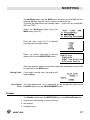
1
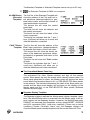
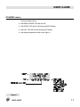
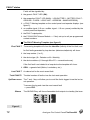
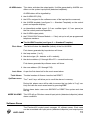
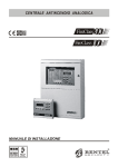
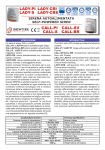
USER GUIDE
®
FC200 - FC200/S - FC200/SL - FC100:
Hereby, Bentel Security,
declares the above mentioned Control Panels to be in compliance with the essential
requirements and other relevant provisions of Directive 1999/5/EC.
The complete R&TTE Declaration of Conformity for each Panel can be found
at www.bentelsecurity.com/dc.html.
These Control Panels comply with EN54-2; EN54-4 1999.
Installation of these systems must be carried out strictly in accordance with the instructions
described in this manual, and in compliance with the local laws and bylaws in force.
The above mentioned Control panels have been designed and made to the highest
standards of quality and performance.
The manufacturer recommends that the installed system should be completely tested
at least once a month.
BENTEL SECURITY Srl shall not assume the responsibility for damage arising from
improper application or use. The above mentioned Control panels have no user-friendly
components, therefore, should be serviced by authorized personnel only.
The following versions of the Fireclass200 series are available:
FC200 - Master panel with 4 A Linear power supply;
FC200/S - Master panel with 2.5 A Switching power supply;
FC200/SL - Slave panel without power supply unit;
Fc100 - Master panel with 2.5 A Switching power supply;
If a technical feature is common to all versions, the name Fireclass200 is used in the description.
If a technical feature applies to a specific version, the name of the version concerned is specified.
Proper functioning of the FireClass200 components can be guaranteed ONLY when ambient
conditions, external to the cabinet, comply with the 3k5 category of IEC 721-3-3:1978.
The Loops of the FireClass200 control panel support 396 Analogue Devices.
The Conventional Zone of the FireClass200 control panel supports30 Conventional Devices.
The Fireclass200 supports a maximum of 512 devices in all.
In order to meet standards and qualify for IMQ Certification, the FC200/SL Slave panel must
be equipped with a BENTEL BA424 (27.6 V - 4 A) Linear power supply or
BENTEL BAQ60/24 (27.6 V - 2.5 A) Switching power supply.
Only the Manufacturer (Access Level no. 4 — refer to “Accss Levels” section) can install the
FC200/SL Slave panel power supply.
The FC200/SL Slave panel can operate ONLY when connected to a FireClass200 Master panel.
BENTEL SECURITY srl reserves the right to change the technical features of this product
without prior notice.
Via Gabbiano 22 - Z.I. S. Scolastica - 64013 CORROPOLI (TE) - ITALY
User guide: Analogue Fire Control Panel FireClass200
Istruzioni Uso Inglese Antinc. FC200/UK
ISTUSOFC200/UK
TABLE OF CONTENTS
FC200 and FC100 . . . . . . . . . . . . . . . . . . . . 4
OVERVIEW
5
Signalling . . . . . . . . . . . . . . . . . . . . . . . . . . 5
LEDs (Visual Signals) . . . . . . . . . . . . . . . . . . 5
Buzzer (Audible Signals) . . . . . . . . . . . . . . . . 7
Display Templates . . . . . . . . . . . . . . . . . . . . 8
The Centralized Master Panel Log . . . . . . . . . . . 9
Repeater Display Template . . . . . . . . . . . . . . . 9
USER GUIDE
11
STANDBY status . . . . . . . . . . . . . . . . . . . . .
11
FAULT status . . . . . . . . . . . . . . . . . . . . . . .
12
The FAULT Warning Template (see figure 2) . . . .
12
ALARM Operating Mode . . . . . . . . . . . . . . . . .
13
The ALARM Template (see figure 3 ---- Standard
Template) . . . . . . . . . . . . . . . . . . . . . . .
15
Software Zones
. . . . . . . . . . . . . . . . . . . . .
15
Positive Alarm Sequence (PAS) . . . . . . . . . . . .
16
Silence . . . . . . . . . . . . . . . . . . . . . . . . . .
16
Reset . . . . . . . . . . . . . . . . . . . . . . . . . . .
16
Test . . . . . . . . . . . . . . . . . . . . . . . . . . . .
17
Day/Night Mode . . . . . . . . . . . . . . . . . . . . .
17
Maintenance request . . . . . . . . . . . . . . . . . .
18
Disable . . . . . . . . . . . . . . . . . . . . . . . . . .
18
Alarm Verify . . . . . . . . . . . . . . . . . . . . . . .
18
Log . . . . . . . . . . . . . . . . . . . . . . . . . . . .
19
Extinction Modes
19
. . . . . . . . . . . . . . . . . . . .
MODIFYING
Disable . . . . . . . . . . . . . . . . . . . . . . . . . .
21
21
Delete Verify (Del. Ver.) . . . . . . . . . . . . . . . . .
24
Delete Log (Del. Log) . . . . . . . . . . . . . . . . . .
25
Telecom Module . . . . . . . . . . . . . . . . . . . . . . . . 25
TABLE OF CONTENTS
3
READING PARAMETER
27
Devices/Zones/Outputs . . . . . . . . . . . . . . . . .
27
Options . . . . . . . . . . . . . . . . . . . . . . . . . .
28
Version . . . . . . . . . . . . . . . . . . . . . . . . . .
28
Log . . . . . . . . . . . . . . . . . . . . . . . . . . . .
29
. . . . . . . . . . . . . . . . . . . . . . . .
30
Print . . . . . . . . . . . . . . . . . . . . . . . . . . . .
Log data
30
Telecom Module . . . . . . . . . . . . . . . . . . . . . 32
FC200 and FC100 Features
FC200
FC100
EN54 Approved
EN54 Approved
2 analogue loop: supports 99 sensors and 99 1 analogue loop: supports 99 sensors and 99
modules
modules
Automatic device-drift compensation
Automatic device-drift compensation
Modular loop management
1 conventional input line: supports 30 fire detec- 1 conventional input line: supports 30 fire
tors and an unlimited number of Callpoints
detectors and an unlimited number of Callpoints
16 programmable software zones
16 programmable software zones
16 alarm repeat outputs (open-collectors): 1 16 alarm repeat outputs (open-collectors): 1
per zone
per zone
1 "C" alarm output
1 "C" alarm output
4 programmable, supervised, silenceable alarm 1 programmable, supervised, silenceable
output (relays) ---- expandable to 16 using FC- alarm output (relay)
200/6OUT expander modules
1 NON-supervised, NON-silenceable ancillary
alarm output (relay)
1 NON-supervised, NON-silenceable Fault output (relay)
RS485 Interface ---- supports 8 repeaters
RS485 Interface ---- supports 8 repeaters
RS232 Interface for serial printer ---- linked to the RS232 Interface for serial printer ---- linked to the
Control panel or a PC for upload/download opera- Control panel or a PC for upload/download
operations
tions
200 event log
200 event log
Supports 2 FC200/6OUT output expanders to Supports 2 FC200/6OUT output expanders to
provide 16 outputs
provide 13 outputs
Local/Remote Upload/Down load from PC
Local/Remote Upload/Down load from PC
TELECOM Module (Accessory item)
TELECOM Module (Accessory item)
Power supply: 230 Vca +/- 10%
Power supply: 230 Vca +/- 10%
Available with 2.5 A power supply/battery charger Available with 2.5 A power supply/battery
and with 27.6V-4A linear power supply
charger
Housing for 2 x 17 Ah batteries
Housing for 2 x 17 Ah batteries
Dimensions (w x h x d): 432 x 577 x 131 mm
Dimensions (w x h x d): 432 x 577 x 131 mm
Weight (without batteries): max. 9.0 Kg
Weight (without batteries): max. 9.0 Kg
FC200 and FC100
The Installer and Operator manuals can be used with FC200 and FC100
Fire Control panels, however, where features and capacity differ, refer to
the above table.
4
Analogue Fire Control Panel FireClass200
OVERVIEW
Please read this manual carefully to get an overall view of how to use your
FireClass200 system. The configuration of the FireClass200 system depends
on the size and requirements of the application, therefore, some of the devices
and functions described may not be present on your system.
The FireClass200 Master control panel supports:
8 FC200/REP Repeaters
7 FC200/SL Slave control panels
FireClass200
FireClass200 allows users to control all the functions of the fire control system.
Repeaters
Repeaters are peripherals that provide all the system status information
(Standard Template ---- refer to page 10), emit audible signals and allow
users to control the main functions of the FireClass200 system (SILENCE,
RESET and ACKnowledge).
FC200/SL panels
The FC200/SL panels are secondary panels which can be used to expand
the FireClass200 system.
+
FireClass control panels 4.0 firmware version and Repeaters 1.2 firmware
version cannot operate on applications using Fire-Class control panels and
Repeaters with lower firmware versions.
Signalling
The system status is indicated by the:
- control panel LEDs;
- back-lighted display (20 characters on 4 lines);
- buzzer.
LEDs (Visual Signals)
ALARM
ON: - ALARM status. In the event of false alarm - press the SILENCE button to stop the SILENCEABLE Outputs temporarily or the RESET button to
stop all the outputs permanently.
MORE ALARMS
ON: - ALARM status on more than one of the input points (detectors/callpoints). It is possible to view all the input points in ALARM status.
PREALARM
Blinking: - PREALARM status. The control panel will generate an alarm when
the pre-alarm delay ends. In the event of false alarm ---- press the RESET key
to stop the procedure.
TELECOM
OVERVIEW
ON: - the telephone line is connected to the control panel.
5
MAIN POWER
(green)
OFF: - Mains power failure (230 V). Check for blackout in the local area. If
the local area power supply is functioning normally, immediate maintenance is required! The batteries will provide the power supply until Mains
power is restored.
WALK TEST
Blinking: - at least one software zone is in Test status. The outputs of the
zone concerned will be activated for approximately one second when the
zone triggers alarm status. If the zone in Test status triggers an alarm, the
extinction outputs of the will not be activated.
DISABLED
ON: - at least one device has been disabled. Use the Disable option from the
MODIFYING menu to view/change the status of disabled devices.
NIGHT
ON: - NIGHT Mode ACTIVE. The system will adhere to the programmed Alarm
Threshold values of the input points (detectors/callpoints). If the SILENCE button
is pressed during NIGHT mode ---- SILENCE status will be held for the programmed SILENCE time.
DAY
ON: - DAY Mode ACTIVE. The system will increase the programmed
Alarm Threshold values of the input points (detectors) by a pre-set value,
in this way the input points (detectors) will be less prone to false alarms
caused by persons in the protected ambient. If the SILENCE button is
pressed during DAY Mode ---- SILENCE status will be held until the SILENCE button is pressed again.
FAULT
ON: - at least one FAULT has been detected. The LEDs and/or the display
will indicate the FAULT type.
MAIN (red)
As per the green MAIN POWER LED. This LED will go ON during Mains
power failure (the MAIN LED has memory function).
LOW BATTERY
ON: - the control panel batteries are low and will be unable to power the control
panel properly in the event of blackout. Wait for several hours for the batteries to
recharge. If the LED remains ON, immediate maintenance required!
BATTERY
FAULT
ON: - the batteries are either disconnected or empty or the battery protection fuse has burnt out (refer to FUSES LED). If this status is not cleared,
the control panel will be unable to operate in the event of blackout.
GROUND
ON: - the control panel is leaking to Ground. Maintenance required!
FUSES
LOGIC UNIT
ADDRESS
SAME ADDRESS
6
ON: - either the polarity fuse or the 24 V output fuse has burnt out, in the
latter case, the devices connected to the 24 V output will be unable to operate (the display will indicate the fuse concerned). Immediate maintenance required!
ON: - the control panel has blocked. Immediate maintenance required!
ON: - a Loop device (detector/callpoint) is missing. Maintenance required!
ON: - Configuration error. Maintenance required!
Analogue Fire Control Panel FireClass200
SILENCE
Z01... Z16
ON: - the Silenceable Output Points have been forced into standby status.
Press the SILENCE button to restore the previous status. Silenced Output
Points will be released automatically if another alarm condition occurs or
after the programmed NIGHT Mode SILENCE Time.
ON: - the respective zone is in ALARM status.
In the event of false alarm ---- press SILENCE to force the SILENCEABLE
Outputs into standby or press RESET to deactivate all the outputs completely.
Blinking: - (3 sec. ON - 1 sec. OFF) the corresponding zone is in PREALARM
status. The zone will go into ALARM status after the programmed Prealarm
Time or will start the FIXED delay (if programmed).
In the event of false alarm ---- press RESET to stop the automatic procedure.
Blinking: - (1 sec. ON - 0,5 sec. OFF) the FIXED delay is running. The Zone
will go into ALARM status when the programmed delay ends.
In the event of false alarm ---- press RESET to stop the automatic procedure,
or press ACK to add the PAS delay to the FIXED delay.
Blinking: - (1 sec. ON - 2 sec. OFF) the PAS delay has been added to the
running FIXED delay. The Zone will go into ALARM status when the total time
of both delay ends.
In the event of false alarm ---- press RESET to stop the automatic procedure.
Press TEST to check the LEDs are operating properly.
Buzzer (Audible Signals)
The control panel buzzer provides audible indication of the panel status.
3 sec. sound
1 sec. pause
1 sec. sound
0.5 sec. pause
1 sec. sound
2 sec. pause
PREALARM status
FIXED Delay running
PAS delay running
0.2 sec. sound
0.2 sec. pause
Control panel in ALARM status
05 sec. sound
0.5 sec. pause
FAULT
1 sec. sound
9 sec. pause
FAULT in memory
1 sec. sound
2 sec. pause
SILENCE active
0.3 sec. sound
0.3 sec.pause
RESET running
2 sec. sound
1 sec. pause
OVERVIEW
Zone in TEST status
7
To test the buzzer press TEST.
The buzzer cannot work during the SILENCE phase.
Display Templates
STANDBY
status
This status will be indicated by the
STANDBY template. The top line will show
the control panel label and the bottom line
will show the current Time, date and day
of the week.
WARNING
status
This status will be signalled by the WARNING template. The panel will generate a
warning when an input point (detector) exceeds its warning threshold and there is
risk of an alarm.
PREALARM
status
This status will be signalled by the PREALARM template. The control panel will
generate an alarm when the programmed
prealarm time ends.
FIRE CLASS 2ØØ
Scanning Loop
>> >> >>
16:23 Ø2/Ø8/99 Mon
Panel
in
WARNING
state !
PREALARM
001/002
FIRE CLASS 200
Device:
Sen1/01
Software Zone
02
The system repeaters will provide the relative information, and the ↑ and ↓
keys will allow you to scroll and view the events concerned. In this case,
the ESC key will not allow you to access the Events log.
ALARM Status
(Standard
Template)
8
The first line of the Standard Template
will show the address of the First input
point/zone (detector/callpoint) to generate
alarm status.
The second line will show the address of
the Last input point/zone (detector/callpoint) to generate alarm status.
The third line will show the Total number
of input points/zones (detectors/callpoints)
in alarm status.
The fourth line indicates that the ↑ and ↓
keys (Up/Down) will allow you to scroll
and view the input points/zones (detectors/callpoints) concerned.
First Alarm
Last
Alarm
Total Alarms
Up/Down move
: ####
: ####
: ###
: ####
Analogue Fire Control Panel FireClass200
The Standard Template or Extended Template can be set up via PC only
+
The Extended Template is EN54 non-compliant.
ALARM Status
(Extended
Template)
The first line of the Extended Template will
show the address of the First and Last input point/zone (detector/callpoint) to generate alarm status and the total number of
input points/zones concerned.
The second line will show the control
panel label.
The third line will show the detector and
the module concerned.
The fourth line will show the labels of the
zones concerned.
The fourth line indicates that the ↑ and ↓
keys (Up/Down) will allow you to scroll and
view the detectors concerned.
FAULT Status
Template
The first line will show the address of the
First input point/zone (detector/callpoint)
to generate fault status or the Fault code..
The second line will show the device address of the Last input point/zone (detector/callpoint) to generate fault status or the
Fault code.
The third line will show the Total number
of faults.
The fourth line indicates that the ↑ and ↓
scroll keys (Up/Down) will allow you to
view the addresses and codes concerned.
A L ARM
001/002
FIRE CLASS
Device:
Sen1/01
Software Zone
01
First Fault
Last
Fault
Total Faults
Up/Down move
: ####
: ####
: ###
: ####
The Centralized Master Panel Log
The centralized Fire Class Master retrieves and logs all the network
events. Slave panels log only the events which directly concern them. If a
Slave panel generates an alarm, the Master panel will retrieve the alarm
event details and broadcast them to ALL or PRE-SELECTED Slave panels
in the network. The retrieved information (the label of the Slave panel concerned and the alarm event details) will be shown on the displays of the
Master panel and ALL or the PRE-SELECTED Slave panels (Software
manuals-System page).
Repeater Display Template
The Repeater displays replicate the Master panel display template, therefore, if the Modify/Read menu is accessed from the Master panel, it will appear instantly on the Repeater displays. However, the Modify/Read menu
CANNOT be accessed from Repeaters as they accept RESET, SILENCE
and ACK commands ONLY (code entry required). If there are no active
conditions (Trouble, Pre-Alarm, Alarm, etc.), the Repeater displays will
show the Master panel standby template with the current Date and Time.
OVERVIEW
9
ALARM Status
(Extended
Template)
FireClass panel firmware versions 4.00 with Repeater firmware versions1.2 provide an Alarm Template option (refer to Standard Template or
Extended Template). The Alarm Template can be set up via PC only.
The example below signals Alarm on Module1 Loop1. The first line shows
the ALARM event no. 1 of 2 active events. The third line shows the label
(maximum 16 characters) of the detector or Module in alarm status. The
fourth line of the zone the detector or module belongs to.
The ↑ and ↓ scroll keys (Up/Down) will allow you to view the templates of
the various detectors in alarm status. In the event of two active alarms, the
control panel will alternate between the two alarm templates every two
seconds.
ALARM
001/002
FIRE CLASS 200
Device:
Sen1/01
Software Zone
01
10
Analogue Fire Control Panel FireClass200
USER GUIDE
STANDBY status
During standby status:
the MAIN POWER LED will be ON;
the NIGHT LED will be ON (during NIGHT Mode);
the DAY LED will be ON (during DAY Mode);
the display template will be as per figure 1.
Figure 1
USER GUIDE
11
FAULT status
Faults will be signalled by:
the generic FAULT LED (ON);
the respective FAULT LED (MAIN - LOW BATTERY - BATTERY FAULT GROUND - FUSES - LOGIC UNIT - ADDRESS - SAME ADDRESS);
a FAULT Warning template on the control panel and repeater displays (see
figure 2);
an audible signal (0.5 sec. audible signal - 0.5 sec. pause) emitted by the
control panel and repeaters;
the FAULT output points;
the FC200/COM Telecom Module ---- if duly set up to call pre-programmed
contact numbers.
The FAULT Warning Template (see figure 2)
First FAULT
The warning template will show the Identifier (initials) of the first fault, and
for first faults generated by loop devices (detectors/callpoints) will show:
the loop number (1 or 2);
the device type (S = Detector or M = Module);
the device address (01 through 99 or ZC = conventional zone).
If the first fault is not related to a loop-device the template will show:
GEN. - a generic fault (Mains, Low battery, etc.).
Last FAULT
Total FAULTS
Up/Down move
As above but for the most recent fault.
The total number of faults since the last reset operation.
The ↑ and ↓ keys will allow you to scroll the faults logged since the last reset operation.
To access the log and view the most recent fault
---- press ESC.
Silence
The SILENCE key will force silenceable-fault-outputs to standby (the buzz-
Figure 2
12
Analogue Fire Control Panel FireClass200
ers will be unable to function during the SILENCE phase).
Memory
Reset
+
Fault memory will be signalled by blinking on the respective LED.
The RESET key can be used to force ALL fault outputs to standby and
clear the fault memory.
The fault outputs will restore automatically to standby when faults clear.
RESET will be necessary for faults directly related to fault-outputs.
ALARM Operating Mode
The FireClass200 control panel can be programmed to provide WARNINGS and PREALARMS.
WARNING status
This status indicates that an input point (detector) has exceeded its warning threshold and, if the condition continues, will trigger an alarm.
The WARNING phase will be signalled by the WARNING template on the
control panel and repeater displays:
Panel
in
WARNING
state !
WARNING status will also be signalled by:
the WARNING output points;
the FC200/COM Telecom Module ---- if duly set up to call pre-programmed
contact numbers.
During the WARNING phase you will be able to access the log (refer to
"Log" section) and view the most recent event by pressing ESC.
PREALARM
status
This status indicates that an input point (detector) has exceeded its alarm
threshold. The control panel will not generate an alarm until the preset prealarm-time ends. However, if a second input point (detector) detects alarm
conditions during the Prealarm phase, the control panel will generate an
instant alarm.
PREALARM status will be signalled by the PREALARM template on the
control panel and repeater displays.
USER GUIDE
13
PREALARM
001/002
FIRE CLASS 200
Device:
Sen1/01
Software Zone
01
The first line of the PREALARM template will alternate between the first
and last event and will indicate the total number of detectors/modules in
prealarm status.
The third line will show the label of the first/last detector/module to generate prealarm status.
The fourth line will show the label of the zone concerned.
The ↑ and ↓ keys will allow you to scroll and view the detectors/modules
concerned.
The prealarm templates of the first and last events will alternate on the
control panel and repeater displays every two seconds.
NOTE: If the control panel is operating in NIGHT mode, it will generate INSTANT ALARMS ONLY (Prealarm status will be bypassed automatically).
If an alarm procedure is already running, the control panel will ignore prealarm conditions.
NOTE: Instant alarms (e.g. from callpoints) will override prealarm status.
PREALARM status will also be signalled by:
blinking on the ALARM and PREALARM LEDs (3 sec. ON - 1 sec. OFF);
blinking on the LED associated with the software zones of the input point
concerned (3 sec. ON - 1 sec. OFF);
an intermittent audible signal (3 sec. audible signal - 1 sec. pause) on the
fire control panel and repeaters;
the prealarm output points;
the FC200/COM Telecom Module ---- if duly set up to call pre-programmed
telephone numbers.
During the PREALARM phase you will be able to SILENCE or RESET the
system and view the log.
NOTE: In this case, the ESC key will not access the events log.
Figure 3
14
Analogue Fire Control Panel FireClass200
ALARM status
This status activates the output points. It will be generated by ALARM conditions on the system input points (detectors/callpoints).
ALARM status will be signalled by:
the ALARM LED (ON);
the LEDs assigned to the software zones of the input points concerned;
the ALARM template (see figure 3 ---- Standard Template) on the control
panel and repeater displays;
an intermittent audible signal (0,2 sec. audible signal - 0,2 sec. pause) on
the fire control panel and repeaters;
the ALARM output points;
the FC200/COM Telecom Module ---- if duly set up to call pre-programmed
telephone numbers.
The ALARM Template (see figure 3 ---- Standard Template)
First Alarm
This field will show the Identifier (initials) of the first ALARM.
First alarms generated by loop devices will show:
the loop number (1 or 2);
the device type (S = detector or M = module);
the device address (01 through 99 or ZC = conventional zone).
First alarms generated by software zones will show:
the zone address (Z01 through Z16).
Last Alarm
Total Alarms
Up/Down move
As per the first alarm but for the most recent alarm.
The total number of Alarms since the last RESET.
The ↑ and ↓ keys will allow you to scroll the alarms in memory.
During this phase users will be able to access the log (refer to "Log" section) and view the most recent event by pressing ESC.
During alarm status users can SILENCE or RESET the system and view
the log.
MORE ALARMS
This LED will go ON when several input points (detectors/callpoints) detect
alarm conditions.
Software Zones
The Fireclass200 control panel manages 16 software zones. Each zone
can be associated with input points (detectors/callpoints) and output points
USER GUIDE
15
(hornstrobes, etc.). The software zone output points (hornstrobes, etc.) will
activate when the zone generates an alarm.
Positive Alarm Sequence (PAS)
The software zone (enabled for the Fixed Delay) will go into alarm status
when the Fixed Delay ends.
To extend a running Fixed Delay ---- press ACK.
The PAS Delay (if enabled) will be added to the Fixed Delay.
The software zone will go into alarm status when the delay ends.
Fixed Delay will be signalled by blinking on the respective zone LED (1
sec. ON - 0.5 sec. OFF) and by an intermittent audible signal (1 sec. audible signal - 0.5 sec. pause);
PAS Delay will be signalled by blinking on the respective zone LED (2 sec.
ON - 2 sec. OFF) and by an intermittent audible signal (2 sec. audible signal - 2 sec. pause)
+
If several input points (detectors/callpoints) are associated with an output
point (hornstrobe, etc.) the latter will activate when one or more of its input
points detects ALARM conditions.
Silence
The SILENCE button can be used to force Silenceable output points to
standby status:
In NIGHT Mode - Silence status will be held for the preset Silence time;
In DAY Mode - Silence status will be held until the SILENCE button is
pressed again.
+
In both operating modes - new alarm conditions will annul Silence status
automatically.
Reset
RESET operations can be done from the control panel.
RESET will stop Alarm, Prealarm, Warning and FAULT conditions.
Access to this command is limited to authorized key holders only (access
level 2: code or mechanical key).
During RESET the control panel template will be as follows:
16
Analogue Fire Control Panel FireClass200
RESET
RUNNING
Please Wait ...
The system will reprocess any alarm, prealarm, warning or fault signal
which is not cleared by RESET operations.
Command keys (including ESC) cannot be used when RESET is running.
The repeaters can be RESET by the installer or user code PINs.
Test
The TEST button will activate all the control panel and repeater LEDs and
buzzers.
The FC200/COM Telecom Module (if duly programmed) will call the programmed telephone numbers.
Day/Night Mode
The control panel can operate in DAY or NIGHT Mode.
If the system is silenced during DAY Mode, SILENCE status will be held
until the system is unsilenced (i.e. unless new alarms or faults occur).
If the system is silenced during NIGHT Mode, SILENCE status will be held
for the preset time (refer to "Silence" ).
+
On power up (at default) the system will set to DAY Mode. During this operating mode, silenced alarms/faults will not be unsilenced automatically.
This system provides Automatic Alarm Threshold variation.
The alarm threshold of analogue detectors (preset by the installer) will be
increased during Day Mode, in order to avoid false alarms caused by persons (cigarette smoke, etc.) in the protected ambient.
NIGHT Mode
During Night Mode, the preset value will be restored.
USER GUIDE
17
Maintenance request
The FireClass200 control panel can manage automatic maintenance requests. Maintenance requests will be signalled by a FAULT warning on the
preset date (preset by the installer).
+
The FC200/COM Telecom Module (if duly programmed) will call the programmed telephone numbers.
Disable
The Disable option from the MODIFYING menu can be used to disable/enable devices, zones and bell outputs (refer to the "MODIFYING"
section for further details).
If you disable a device, the DISABLED LED will go ON.
Disabled devices cannot signal ALARMS, FAULTS, etc.
Alarm Verify
This option will allow the FireClass200 to verify ALARM conditions.
If the Alarm Verify option is enabled, the control panel will take into account the length of time alarm conditions last for, and the number of times
the device (detector/module) concerned detects the respective conditions.
If the Alarm Verify Counter is set at 99, the control panel WILL NOT take
into account the number of times the device (detector/module) detects
alarm conditions, but will only consider the length of time the alarm conditions last for. In this way, the control panel will not generate an alarm until
the set Alarm Verify Time expires.
If the Alarm Verify option is enabled and the Alarm verify Counter is not set
at 0, the template shown during standby status will be as follows:
FIRE CLASS 200
Scanning Loop
Verify Counters >0
16:13 14/01/05 Fri
If the Verify Alarm is programmed for a device the control panel will generate ALARM in accordance with the Verify Time and the Verify Counter.
The control panel will hold standby status for the entire time of the Verify
Alarm operation (Scanning Loops).
18
Analogue Fire Control Panel FireClass200
The number of Alarm Verify operations performed for an input point can be
viewed by means of the Dev./Zones/Outputs option from the READINGS
PARAMETER menu (see "V" field).
Log
The FireClass200 log can record the details of 200 events.
The log is dealt with in detail in the "READING PARAMETERS" paragraph.
Extinction Modes
The FireClass200 "EXTINCTION OUTPUTS" control the fire extinction
systems (water, gas, etc.).
The EXTINCTION OUTPUTS can be programmed to respond to an alarm
after a preset delay. This operating mode will lower the false alarm rate
(unnecessary activation of fire extinction systems). The preset delay will allow users to verify alarms and inhibit or stop fire extinction systems in the
event of false alarm.
+
Inhibit Extinction
If an alarm is generated by a device which is assigned to an Extinction
Output, the Extinction Output concerned will not be activated until the preset delay ends.
To extend a running delay ---- press any Inhibit Extinction button.
The effect of an Inhibit Extinction command on a running delay depends on
the programmed mode:
ADD mode - the Extinction Inhibition command will add 90 seconds to the
preset delay;
STOP mode - the Extinction Inhibition command will stop the delay 10
seconds before it is due to expire. If the Extinction Inhibition command is
undone, the delay will restart and run for 10 seconds;
FULL mode - the Extinction Inhibition command will restore the delay to its
initial value. If the Extinction Inhibition command is undone, the delay will
restart and run for the full preset time.
Silence
You can use the SILENCE button to:
block a running Extinction Output delay.
force activated Extinction Outputs to Standby status.
reactivate Extinction Outputs - forced to Standby status by means of the
SILENCE button. These Outputs will be reactivated after the preset delay.
+
In NIGHT Mode - the Silence status (block delay and force to standby) will
be held for the programmed Silence Time;
USER GUIDE
19
In DAY Mode - the Silence status (block delay and force standby) will be
held until the SILENCE button is pressed again.
In both modes - Silence status will be overridden automatically if a new
ALARM or FAULT condition occurs.
Manual
Extinction
20
Press any Manual Extinction button to activate all Extinction Outputs
without delay.
Analogue Fire Control Panel FireClass200
MODIFYING
The Modifying option from the MAIN menu will allow you to disable the control panel devices, clear the Verify counters and delete the log.
To access the Main Menu from standby status ---- press any key (except RESET and TEST).
Select the Modifying option from the
MAIN menu (press 2).
FIRE CLASS 2ØØ
1= Programming
2= Modifying
3= Reading Parameter
Enter the User Code (11111 at default)
each digit will be masked by Q.
Press ↵ to confirm. If the code is valid the
display will show the MODIFYING menu.
Enter
user
code
*****
Modifying:
1=Disable
2=Del.Ver.3=Del.Log
4=Telecom Module
Select the required option and read the respective paragraph or press ESC
to step back to the MAIN menu.
Wrong Code
If you enter a wrong code, the display will
request Retry.
User code
Wrong !
Retry
XXXXX
User default
Code
The User default code (11111 at default) can be changed by means of the
PassWD option from the PROGRAMMING menu.
Disable
The Disable option from the MODIFYING menu can Disable/Enable the:
loop devices (monitoring or control devices);
bell outputs;
software zones;
MODIFYING
21
network devices (repeaters or slave panels).
The DISABLE LED will go ON when any of the above mentioned is disabled.
The disabled/enabled modes are as follows.
Monitoring
Devices
The control panel will ignore alarm and/or fault signals from disabled monitoring devices (detectors, monitoring modules, conventional zone modules,
addressable call-points), therefore, disabled monitoring devices will be unable to generate alarms or faults.
To clear FAULTS generated by monitoring devices - Disable the monitoring device concerned.
To clear ALARMS generated by monitoring devices - RESET the control
panel.
+
Control Devices
If you enable a monitoring device which has detected an ALARM or
FAULT condition, it will generate ALARM/FAULT status immediately.
ALARM or FAULT status cannot activate disabled control devices (control
modules, addressable sirens, etc.).
To deactivate control devices activated by faults - Disable the Devices
concerned
To deactivate control devices activated by alarms - RESET the control
panel.
+
Bell Outputs
Software Zones
Repeaters
If you enable a control device during ALARM or FAULT status, it will activate immediately.
The enabled/disabled operating modes of bell outputs are as per control
devices.
The disabled/enabled status of software zones will affect their associated
devices, as previously described.
The control panel will ignore commands from disabled repeaters, however,
their displays will show the control panel template. Loss of a disabled repeater from the network will not generate FAULT status.
To clear FAULT status - generated by the loss of a repeater - Disable the
repeater concerned.
+
Slave panels
The control panel will generate FAULT status when the repeater concerned is re-enabled.
Disabled slave panels cannot generate NETWORK ALARM or NETWORK
FAULT status. Loss of disabled slave panel from the network will not generate FAULT status.
To clear FAULT status - generated by loss of an enabled slave panel Disable the panel concerned.
22
Analogue Fire Control Panel FireClass200
To clear NETWORK FAULT status - generated by a slave panels - Disable the Slave panel concerned.
To clear NETWORK ALARM status - generated by a slave panel - RESET
the control panel.
+
+
Procedure
FAULT status will be generated when the slave panel concerned is re-enabled.
NETWORK FAULT status will be generated when the slave panel concerned is re-enabled.
To disable the control panel Items: loop devices; bell outputs; software
zones; network devices.
1.
Select the Disable option from the MODIFYING menu (press 1).
2.
Select the Item, or press ESC to step back
to the MODIFYING menu.
3.
Enter the Item address then press the ↵.
key, or press ESC to step back and select
another Item.
Modifying:
1=Disable
2=Del.Ver.3=Del.Log
4=Telecom Module
MOD: Enab./Disabl.
1=LOOP 1 2=LOOP 2
3=Outputs BELL
4=ZONES
5=NET
MOD: Devices L1
Enter Address
Sensors
L1: 1/##
Modules
L1: 1/__
If a valid address is entered the display will show: ---- the Item label; realtime analogue value; type; address; current status (see figure 4).
4.
Press ↑ or ↓ to change the Item status
then press ↵ to confirm or ESC to quit.
5.
Step back to 3.
Conventional
line
MODIFYING
To enable or disable the conventional line
(terminal 10[LC+]) position the cursor on
the L1 Detector space and press the ↑
key.
MOD: Enab./Disabl.
Device: SENSOR
%##
1/##
STATUS: DISABLED
MOD: Devices L1
Enter Address
Sensors
L1: 1/ZC
Modules
L1: 1/__
23
Non-Configured
Devices
If you enter an invalid address, the display
will show an error message. Press ESC to
quit and step back to 3.
DEVICES LOOP1
Device not
configured
on LOOP 1
Delete Verify (Del. Ver.)
To view the values of the Verify-Alarm counters of the system detectors ---press 2 (Del.Ver.).
Modifying:
1=Disable
2=Del.Ver.3=Del.Log
4=Telecom Module
The Verify Alarm counters may be:
---- ALL at 0 or
All Device with
Alarm Verify 1
Counter=
01
ESC = QUIT
---- with augmented values.
Figure 4
24
Enabled/Disabled status of detectors
Analogue Fire Control Panel FireClass200
Verify Counter > 0
Detector Label 01
Counter=
01
Enter=Clear Counter
The ↓ key will allow you to scroll the Verify-Alarm counters of detectors
with augmented values.
To clear the Verify-Alarm counter of the detector on view ---- press the ↵
key.
NOTE: The counters must be cleared one by one.
Delete Log (Del. Log)
The Delete Log (Del. Log) option from the MODIFYING menu will allow
you to delete the contents of the log.
Select Del. log (press 3).
Press ↵ to delete the contents of the log or
press ESC to quit and step back.
Modifying:
1=Disable
2=Del.Ver.3=Del.Log
4=Telecom Module
MOD: Clear Logger
Are
you sure ?
Yes=Enter No=Esc
Telecom Module
The Telecom Module option from the
Modifying menu (press 4) will allow you
to change the telephone numbers, messages and/or enable/disable the Remote
management option.
Select Numbers (press 1) to change the
programmed telephone numbers.
MODIFYING
Modifying:
1=Disable
2=Del.Ver.3=Del.Log
4=Telecom Module
Mod: Telecom Module
1=Telephone Numbers
2=Messages
3=Remote Management
25
Select the identifier number (1 to 32) of the
telephone number to be changed, and
change as necessary.
Select Messages (press 2) to change, record or listen to the messages.
Enter the identifier number of the message
then press 1 to listen. The display will
show ...
Press ESC to stop the message and step
back. Select Record (press 6) to record or
change messages.
Select Remote Management (press 3) to
enable/disable Teleservice (ON/OFF).
Mod: Telecom Module
Telephone Numbers
Number = 01
____________________
Mod: Telecom Module
Message
=
A = Listen
B = Record
Mod: Telecom Module
Listen
Message
= 1
>>>>>>> ESC=End
Mod: Telecom Module
Recording
Message
= 1
>>>>>>> ESC=End
Mod: Telecom Module
Remote Managem. =OFF
26
Analogue Fire Control Panel FireClass200
READING PARAMETER
The Reading Parameter option from the MAIN menu will allow you to view
all the control panel parameters and to print the log.
Select the Reading Parameter option
from the MAIN menu (press 3). No access
code is required. Viewing and printout do
not affect the parameters and operating
modes of the control panel.
The display will show the READING PARAMETER menu.
FIRE CLASS 2ØØ
1= Programming
2= Modifying
3= Reading Parameter
READINGS:
1=Dev./Zones/Outputs
2=Opt.3=Ver.4=Log.
5=Print 6=M.Telecom
Select the required option and read the respective paragraph or press ESC
to step back to the MAIN menu.
Devices/Zones/Outputs
The Dev./Zones/Outputs option from the READING PARAMETER menu
will allow you to view the parameters of the loop devices, software zones,
bell outputs and network devices.
1.
Select the Dev./Zones/Outputs option
from the READING PARAMETER menu
(press 1) or press ESC to step back to the
MAIN menu.
2.
Select the required option or press ESC to
return to the READING PARAMETER
menu (step 1).
3.
Type in the address of the required Item,
or press ESC to step back to the
Dev./Zones/Network (step 2).
READING PARAMETER
READINGS:
1=Dev./Zones/Outputs
2=Opt.3=Ver.4=Log.
5=Print 6=M.Telecom
RD: Choosing Menu
1=LOOP 1 2=LOOP 2
3=Outputs BELL
4=ZONES
5=NET
RD: Devices L1
Enter Address
Sensors
L1: 1/##
Modules
L1: 1/__
27
+
Position the cursor on Loop 1 then press ↑ to view the parameters of the
conventional line.
If a valid address is entered the display will show the respective data as
described in the "PROGRAMMING" section.
Press ← or → to view the parameters of the other Items of the same type,
or press ESC and type in another address (step 3).
If an invalid address is entered at step 3 ,
the display will show an error message.
Press ESC then enter a valid address.
DEVICES LOOP1
Device not
configured
on LOOP 1
Options
This option from the READING PARAMETER menu will allow you to view
the parameters of the Options.
Select Options from the READING PARAMETER menu (press 2), or press ESC
to step back to the MAIN menu.
The display will show the OPTIONS menu
(refer to "OPTIONS" section). Press ESC
to step back to the READING PARAMETER menu.
READINGS:
1=Dev./Zones/Outputs
2=Opt.3=Ver.4=Log.
5=Print 6=M.Telecom
RD: OPTIONS
Ø=P 1=W 2=V 3=D 4=T
5=S 6=H 7=D 8=Pulse
9=Extinction Mode
Version
The Version option from the READING PARAMETER menu shows the
control panel version.
Select the Version option from the VIEW
PARAMETERS menu (press 3), or press
ESC to step back to the MAIN menu.
The display will show the control panel
version. Press ESC to step back to the
READING PARAMETER menu.
28
READINGS:
1=Dev./Zones/Outputs
2=Opt.3=Ver.4=Log.
5=Print 6=M.Telecom
Fire Class 2ØØ
version
3.Ø
Analogue Fire Control Panel FireClass200
Log
The FireClass200 log stores 200 events. If the log reaches its limit, it will delete old event automatically (starting from the oldest) in order to free locations
for new events.
1.
Select the log option from the READING
PARAMETER menu (press 4), or press
ESC to step back to the MAIN menu.
2.
The display will show the most recent
event.
NOTE:The example shows no.123 as the
most recent event.
3.
Press ← to scroll back.
READINGS:
1=Dev./Zones/Outputs
2=Opt.3=Ver.4=Log.
5=Print 6=M.Telecom
ZONE ALARM
123
FIRE CLASS 2ØØ
Software Zone
15:Ø9 13/Ø7/99
Ø1
ALARM
122
FIRE CLASS 2ØØ
Device: MODULE
15:Ø9 13/Ø7/99 1M13
4.
Press → to scroll forward.
5.
Press ESC to quit and step back to READINGS menu.
When the ← key is pressed on the oldest
event ...
... the most recent event will be shown.
ZONE ALARM
123
FIRE CLASS 2ØØ
Software Zone
15:Ø9 13/Ø7/99
Ø1
FAULT
ØØØ
FIRE CLASS 2ØØ
Missing MAIN
18:Ø2 Ø5/Ø7/99
ZONE ALARM
123
FIRE CLASS 2ØØ
Software Zone
15:Ø9 13/Ø7/99
Ø1
When the → key is pressed on the most recent event, the control panel will
emit an audible error signal.
READING PARAMETER
29
No event
Delete log
If, at step 2, the log is empty (no events),
the display will show the LOGGER
EMPTY message.
ØØØ
LOGGER
EMPTY
The Delete log option from the MODIFYING menu will allow you to delete
the log.
Log data
The following data will be saved in the log (see fig. 5).
Event Type
Event Number
This shows the event description.
This shows the event number (1 through 200).
Panel
This shows the control panel label (Master panel, Slave panel or Repeater)
assigned during programming.
Origin
This shows the label of the Item which generated the event.
Hour/Date
Address
This shows the time and date of the event.
This shows the address of the Item which generated the event.
Print
The Print option from the READINGS menu will allow you to print the log.
1.
Figure 5
30
Select the Print option from the READINGS menu (press 5) or press ESC to step
back to the MAIN menu.
READINGS:
1=Dev./Zones/Outputs
2=Opt.3=Ver.4=Log.
5=Print 6=M.Telecom
Log data
Analogue Fire Control Panel FireClass200
2.
Select the Logger option (press 1) or
press ESC to step back the READINGS
menu.
3.
Press ↵ to start the log printout or press
ESC to quit and step back.
4.
The display will show the template opposite.
+
READINGS
Print:
1= Logger
2= Programming
Logger Print
Start Print ?
Enter = Yes
Esc
= Exit
Logger Print
running
please
wait....
The control panel will continue functioning during the log printout.
Printer not
enabled
If the printer is not enabled, the display will
show the respective template.
Printer not
connected
The serial printer must be connected to the control panel serial port.
Printer not
enabled !
Enable in
menu’ PRG:SYSTEM
The control panel will ignore the printer status (disconnected, paper out, no
ink, blocked, etc.).
Stop Print
Print
Programming
To stop the Print command - proceed as
per start Print. At step 3 press (after
pressing ↵) the display will show the template opposite. At this point, press ↵ to
stop the Print or ESC to step back.
Logger Print
running
stop ?
Yes = Enter
The Programming option from the PRINT menu is reserved for future use.
If the Programming option is selected
from the PRINT menu ...
READING PARAMETER
READINGS
Print:
1= Logger
2= Programming
31
... the template will be as opposite.
Programming Data
Print
Future Use
Future Use
Press ESC to step back to the PRINT menu (step 2).
Telecom Module
The Telecom Module option from the PARAMETER READING menu will allow you
to view the Telecom Module settings.
READINGS:
1=Dev./Zones/Outputs
2=Opt.3=Ver.4=Log.
5=Print 6=M.Telecom
Select Tel.Mod. from the PARAMETER READING menu (press 6), or
press ESC to stepback to the Main menu.
The display will show ...
Rd. :Telecom Module
1=Telephone Numbers
2=Messages
3=Remote Management
Select Telephone numbers (press 1) to view the programmed Telephone
numbers (01 to 32).
The display will show ...
Select Messages (press 2) to listen to the
messages recorded during the programming phase of the Telecom Module.
Rd. :Telecom Module
Telephone Numbers
Number
: 01
____________________
Rd. :Telecom Module
Message
= 1
A = Listen
Select Remote Management (press 3) to enable/disable (ON / OFF) Teleservice.
The display will show ...
Rd. :Telecom Module
Remote Managem.= OFF
ISTUSOFC200/UK 1.0 301105 BUU