1
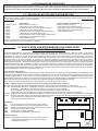
5.3 INPUT CONTROL TERMINAL BOARD MR4
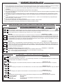
START - OPEN
terminals 42 - 22
N.O. input, activated via dip switch no.2 (SW1) as START or OPEN.
42 If activated as a START command, the inputs fulfil the sequence selected by dip switches 3 and 4 (SW1).
If activated as an OPEN command, it just fulfils the function of opening the gate. If any clocks are installed, they are connected to the OPEN
22 input: by keeping this input activated, the gate will remain open to then close again only when the contacts are free.
START
COM
S. PED
43
COM
22
COM
22
STOP
10
SFC
18
COM
22
SFA
19
COM
SFC
SFA
22
18
19
SFA+SFC
22
PED. S.- CLOSE
terminals 43 - 22
N.O. input activated via dip switch no.2 (SW1) as PEDESTRIAN START or CLOSE. If selected as the PEDESTRIAN START command, it is just
activated when the gate is closed and is used to open the gate partially. If selected as a CLOSE command, it is used to close the gate at any time.
STOP
terminals 22 - 10
N.C. safety input. When it is activated, it stops the gate immediately then when a start command is given the gate is opened.
During a pause time (if programmed) a stop command eliminates the automatic closing command, leaving the gate open waiting for further inputs.
SFC
terminals 18 - 22
N.C. or resistive input (8K2W) with safety function and photocell during closing. This safety function is only enabled during the closing phase
where the risk of impact must be protected. When the SFC input is activated the gate opens completely. For information on how this input
works, see the setting of dip switches SW2.
SFA
terminals 19 - 22
N.C. or resistive input (8K2W) with safety function and photocell during opening. This safety function is only enabled during the opening
phase and causes the gate to stop and commands a short closing input. This input is used to protect the intermediary zones between the
opening of the leaf and fixed obstacles such as walls or dividers where the risk of impact or crushing must be protected. This safety function
has no effect in the closing phase. For information on this input, see the setting of dip switches SW2.
SFA + SFC
terminals 18 - 19 - 22
The simultaneous opening of the SFC and SFA contacts causes the movement to stop temporarily until the above-mentioned safety functions
are restored to then open again when they are freed.
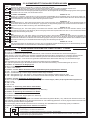
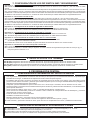
6. CONFIGURING DIP SWITCHES SW1 (LOGIC)
Dip switch no. 1: It selects the operating logic
Off: Hands on logic.
The gate works by holding the controls down, disabling the radio receiver connected.
- Turn Dip switch no. 2 OFF and the start command fulfils the opening function, when released it stops the movement and when pressed
again, it closes the gate. The PED START command is disabled.
- Turn Dip switch no. 2 ON and the gate is controlled by holding the differentiated opening and closing controls down:
The Start command becomes an OPEN command and the Pedestrian Start command becomes a CLOSE command.
On: Logic for jog controls with operation in semi-automatic or automatic mode depending on how dip switches 3 and 4 are set.
Dip switch no. 2: Functions of the N.O. inputs.
Off: Start and PED Start
On: Open and Close
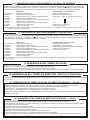
Dip switches no. 3 and 4: They select the reaction to the sequence of start commands (excluding “hands on”)
Off - Off: Step-step type 1:open-stop-close-stop-open
Off - On: Step-step type 2: open-stop-close-open-stop-close
On - Off: Apartment block type 1: open only, a start closing in pause and a start re-opening in closing.
On - On: Apartment block type 2: open only and no start accepted in pause; a start re-opening in closing
Dip switches no. 5 and 6: Leaf delay in opening phase.
Off - Off: 0 sec. When programming a single leaf (1 motor) it is obligatory for the dip switches to be set in this manner.
Off - On: 2 sec.
On - Off: 3.5 sec.
On - On: 5 sec.
Dip switches no. 7: Rebound in opening and closing phase.
Off: Rebound disabled
On: Rebound enabled in closing and opening phase (just on motor M1)
Dip switch no. 8: Enable pre-flashing function on flashing light.
Off: Pre-flashing function disabled.
On: Pre-flashing function enabled for 3 sec. for each N.O. command.
Dip switch no. 9: Flashing light functions
Off: Different flashing functions based on the status of the gate: slow flashing frequency during opening (1 Hz), light on steady during
pause time, fast flashing frequency during closing (2 Hz). When the gate is closed or completely open, without a programmed pause
time, or following a stop command: flashing light off.
On: Fixed output during motor manoeuvring: a self-flashing luminous indicator must be installed (SLR).
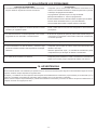
Dip switch no. 10: Functions of the output of the AUX relay and 2nd radio channel
Dip 10 Jumper J9
Off:
Output of AUX relay and 2nd radio channel
Pulse output of 2nd radio channel on AUX relay
On:
Pulse output of 2nd radio channel directly on input PED. S. - CLOSE.
Output of timed AUX relay during manoeuvre + 90 sec., can also be activated for 90 sec.
by opening the STOP command when the gate is closed.
- 15 -