1
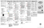
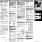
ASSEMBLY
-4)
SCHEMA DI MONTAGGIO
-
-1)
-5)
-2)
Componenti a
carico del cliente.
Esempio
solo indicativo.
Customer's
components.
Only example.
-6)
-3)
016376000
REV.00
ENGLISH (Translated from Italian)
A
INDEX
A
B
C
INDEX
MACHINE AND MANUFACTURER IDENTIFICATION
DECLARATION OF INCORPORATION OF
PARTLY-COMPLETED MACHINERY
MACHINE DESCRIPTION
D1
MOVING AND TRANSPORT
GENERAL WARNINGS
FIRST AID RULES
GENERAL SAFETY RULES
TECNICAL DATA
H1
PERFORMANCE SPECIFICATIONS
ELECTRICAL SPECIFICATIONS
OPERATING CONDITIONS
L1
ENVIRONMENTAL CONDITIONS
L2
ELECTRICAL POWER SUPPLY
L3
DUTY CYCLE
L4
FLUIDS PERMITTED / FLUIDS NOT PERMITTED
INSTALLATION
M1
PRELIMINARY INSPECTION
M2
POSITIONING THE PUMP
M3
NOTES ON SUCTION AND DELIVERY LINES
M4
CONFIGURATION AND ACCESSORIES
M5
LINE ACCESSORIES
CONNECTIONS
N1
ELECTRICAL CONNECTIONS
N2
CONNECTING THE PIPING
INITIAL START-UP
DAILY USE
MAINTENANCE
NOISE LEVEL
PROBLEMS AND SOLUTIONS
DEMOLITION AND DISPOSAL
D
E
F
G
H
I
L
M
N
O
P
Q
R
S
T
ENGLISH (Translated from Italian)
F
ENGLISH (Translated from Italian)
FIRST AID RULES
I
Contact with
the product
In the event of problems developing following eye/skin
contact, inhalation or ingestion of the treated product, please
refer to the safety data sheet
Persons who
have suffered
electric shock
Disconnect the power source, or use a dry insulator to
protect yourself while you move the injured person away
from any electrical conductor. Avoid touching the injured
person with your bare hands until he is far away from any
conductor. Immediately call for help from qualified and
trained personnel. Do not operate switches with wet hands.
NOTE
Please refer to the safety data sheet for the product
SMOKING
PROHIBITED
When operating the dispensing system and in particular during refuelling, do not smoke and do not use
open flame.
G
Wear protective equipment that is:
suited to the operations that need to be performed;
resistant to cleaning products.
Wear the following personal protective equipment during handling and installation:
safety shoes;
Protective
equipment
instruction manual
Protective
gloves
Prolonged contact with the treated product may cause
skin irritation; always wear protective gloves during dispensing.
DANGER
Never touch the electric plug or socket with wet
hands.
Do not switch the dispensing system on if the network connection cable or important parts of the apparatus are damaged, such as the inlet/outlet pipe,
nozzle or safety devices. Replace the damaged pipe
immediately.
Before each use, check that the network connection
cable and power plug are not damaged. Have the
network connection cable replaced immediately by
a qualified electrician.
The electrical connection between the plug and
socket must be kept well away from water.
Unsuitable extension leads can be dangerous. In
accordance with current regulations, only extension cords that are labelled for outdoor use and
have a sufficient conduction path should be used
outdoors.
During operation a few parts may reach high temperatures and result in burns if touched
TECNICHAL
DATA
ATTENTION
DECLARATION OF INCORPORATION OF
PARTLY-COMPLETED MACHINERY
ATTENTION
The documentation is at the disposal of the competent authority following motivated
request at Piusi S.p.A. or following request sent to the e-mail address: doc_tec@piusi.
com
The person authorised to compile the technical file and draw up the declaration is Otto
Varini as legal representative.
Self-Priming, volumetric, rotating vane pump, equipped
with by-pass valve..
Brush motor, DC, low tension with intermittent cycle,
closed type in protection class IP55 according to CEI-EN
60034-5, directly flanged to the pump body.
MOTOR
D1
MOVING AND TRANSPORT
12
L
TEMPERATURE
Important
precautions
Symbols used
in the manual
To ensure operator safety and to protect the pump from
potential damage, workers must be fully acquainted with
this instruction manual before performing any operation.
The following symbols will be used throughout the manual
to highlight safety information and precautions of particular importance:
ATTENTION
This symbol indicates safe working practices for operators and/or potentially exposed persons.
WARNING
This symbol indicates that there is risk of damage to
the equipment and/or its components.
NOTE
This symbol indicates useful information.
Manual preservation
Reproduction
rights
This manual should be complete and legible throughout. It
should remain available to end users and specialist installation and maintenance technicians for consultation at any
time.
All reproduction rights are reserved by Piusi S.p.A. The text
cannot be reprinted without the written permission of Piusi
S.p.A.
© Piusi S.p.A.
THIS MANUAL IS THE PROPERTY OF PIUSI S.p.A.
ANY REPRODUCTION, EVEN PARTIAL, IS FORBIDDEN.
Always install a foot valve to prevent the suction pipe
from being emptied and to keep the pump wet at all
times. In this way, the pump will always start up immediately the next times it is used. When the system is in
operation, the pump can operate with back pressures of
up to 0.5 bars on the suction inlet; beyond this point, the
pump may begin to cavitate resulting in a drop of the
flow rate and an increase in the noise levels of the system. In light of this, it is important to guarantee small
back pressures on the suction side, by using short pipes
with diameters that are equal to or larger than those
recommended, reducing bends to a minimum, and using filters with a large cross-section and foot valves with
minimum possible resistance on the suction side.
ATTENTION
It is very important to keep the suction filters clean
because, when they become clogged, they increase
the resistance of the system.
The temperature limits shown apply to the pump
components and must be respected to avoid possible damage or malfunction.
N.B.: THE PUMP SHOULD BE POWERED BY A SAFE
SOURCE: BATTERY OR POWER SUPPLY 12/24V WITH
SAFETY TRANSFORMER.
In accordance with the model, the pump must be
powered by a direct current line, the nominal values of
which are indicated on the table in the paragraph “I –
ELECTRICAL SPECIFICATIONS”.
The maximum acceptable variations from the electrical
parameters are:
Voltage: +/- 10% of the nominal value
The vertical distance between the pump and the fluid
must be kept as short as possible, and it must fall within
the 2m maximum required for priming. If the distance
is greater, a foot valve must be installed to allow the
suction pipes to fill up and the diameter pipes must be
larger. It is however recommended that pump not be installed if the vertical distance is greater than 3m.
The pumps have been designed for intermittent
use and a 20-minute duty cycle under conditions of
maximum back pressure.
ATTENTION
Functioning under by-pass conditions is only
allowed for short periods of time (max. 3 minutes).
A
(Maximum Flow
Rate)
50
B
48
C
46
(High Flow Rate)
D
(By pass)
0
12
15
24
8
12
16
24
8,5
12
17
24
9
12
21
24
12
t
t
t
t
t
Delivery Closed
4
5
6
7
1
2
3
4
5
6
7
8
9
10
11
12
13
- PUMP OXIDATION
- CONTAMINATION OF THE
SAME
- PUMP CORROSION
INJURY TO PERSONS
- FIRE – EXPLOSION
DAMAGE TO GASKET SEALS
- MOTOR OVERLOAD
M2 POSITIONING THE PUMP
The curve refers to the following operating conditions:
Fluid
Diesel Fuel
Temperature
20° C
Suction Conditions The tube and the pump position relative to the fluid level is such that a pressure of 0.3 bar is generated at the nominal flow
rate.
Under different suction conditions higher pressure values can be created that reduce the flow
rate compared to the same back pressure values.
To obtain the best performance, it is very important to reduce loss of suction pressure as much as
possible by following these instructions:
t4IPSUFOUIFTVDUJPOUVCFBTNVDIBTQPTTJCMF
t"WPJEVTFMFTTFMCPXTPSUISPUUMJOHJOUIFUVCFT
t,FFQUIFTVDUJPOöMUFSDMFBO
t6TFBUVCFXJUIBEJBNFUFSFRVBMUPPSHSFBUFS
than, indicated (see Installation)
THE MOTORS ARE NOT OF THE ANTI-EXPLOSIVETYPE. DO NOT install them where inflammable vapours could be present.
It is the responsibility of the installer to provide the
necessary line accessories to ensure the correct and
safe operation of the pump. The accessories that
are not suitable to be used with the previously indicated material could damage the pump and/or
cause injury to persons, as well as causing pollution.
To maximise performance and prevent damage
that could affect pump operation, always demand
original accessories.
M3 NOTES ON SUCTION AND DELIVERY LINES
DELIVERY
FOREWORD
USE
PROCEDURE
ELECTRICAL CONNECTIONS
Comply with the following (not exhaustive) instructions
to ensure a proper electrical connection:
1
3
ATTENTION
For connection the installer shall have to use a cable
of adequate diamater for the cable gland to ensure
protection grade IP55.
SPECIFICATIONS
Cables with faston connector coupling for connection to the power supply line
1
RED cable: positive pole (+)
2
BLACK cable: negative pole (-)
3
Terminal strip box (protection class IP55 in conformance with the directive
4
EN 60034-5-97) complete of:
4A ON/OFF switch;
4B Safety fuse against short circuits and overcurrent,25a fuse for 12v models
4C Safety fuse against short circuits and overcurrent, 15a fuse for 24v models
power cable complete of pincers for connection to the battery
5
ATTENTION
IT IS THE RESPONSIBILITY OF THE INSTALLER TO
CARRY OUT THE ELECTRICAL CONNECTIONS IN
COMPLIANCE WITH THE APPLICABLE REGULATIONS.
DO NOT INVERT FUSES TO AVOID ANY MOTOR DAMAGE OR MALFUNCTION.
25A FUSE CAN BE FITTED ONLY ON 12V PUMP
15A FUSE CAN BE FITTED ONLY ON 24V PUMP
NOTE
9
4C
The selection of the pump model must be made taking
into account the characteristics of the system.
The combination of the length of the pipe, the diameter
of the pipe, the flow rate of the diesel or other liquid, as
well as the accessories installed on the line, could create
back pressure that are greater than the maximum predicted pressure, thereby causing the pump’s electronic
controls to intervene and reducing the dispensed flow
considerably.
In these cases, to guarantee correct operation of the
pump, it is necessary to reduce the resistance of the system using pipes that are shorter or that have a greater
diameter, as well as line accessories with smaller resistances (e.g. an automatic dispensing nozzle with greater
flow rate capacity).
Maintenance must be performed only by authorized and
properly trained personnel.
SAFETY
WARNINGS
Thanks to the design, the pump requires simple maintenance. Before carrying out any maintenance work,
disconnect the pump from any electrical and hydraulic
power source. During maintenance, the use of personal
protective equipment (PPE) is compulsory. In any case always bear in mind the following basic recommendations
for a good functioning of the pump
Check that the pipe connections are not loose to prevent
any leaks
Check and keep the filter installed on the suction line
clean
Check the pump body and keep it clean and free of any
impurities
Check that the electrical supply cables are in good condition
ONCE A WEEK:
7
R
NOISE LEVEL
BLACK
RED
N2 CONNECTING THE PIPING
FOREWORD
1
2
3
4
O
The provided tubes have a resistivity of <1 MOhm,
as specified by the EN 13617-1 standard. All the installed tubes that are different from those supplied,
must have the above mentioned characteristics.
When the connections are completed, the installer
should check that the resistivity of the assembly complies with the EN 13617 and EN 13612 standards.
The use of tubes that are not suitable could cause
damage to the pump or to persons, as well as pollution. Loosening of the connections (threaded connections, flanges, gasket seals) could cause serious
ecological and safety problems. Check all the connections after the first installation on a daily basis.
If necessary, tighten all the connections.
1
3
4
5
ATTENTION
By-Pass 3000 in line
PRIMING
It is the responsibility of the installer to provide the
necessary line accessories to ensure the correct and
safe operation of the pump. The accessories that
are not suitable to be used with the indicated material could damage the pump or cause injury to persons, as well as causing pollution
IT IS THE INSTALLER’S RESPONSIBILITY TO APPLY
THE FOLLOWING SIGNALS ON THE MACHINE ANYWHERE PUMP WILL BE USED.
Before any connections, please refer to the indications (sticker
on the pump) to detect suction and delivery univocally
Before connecting, make sure that the pipes and the suction tank are free of dirt and thread residue, which could
damage the pump and accessories
Before connecting, make sure that the pipes and the suction tank are free of dirt and thread residue, which could
damage the pump and accessories.
Do not use conical threaded fittings, which could damage the threaded inlet or outlet openings of the pumps if
excessively tightened
If not already fitted, fit a suction filter
recommended minimum nominal diameter: ¾”
nominal recommended pressure: 10 bar
use pipes that are suitable for operation with back pressure
recommended minimum nominal diameter: ¾”
nominal recommended pressure: 10 bar
INITIAL START-UP
13
M5 LINE ACCESSORIES
Under normal working conditions the noise emission
from all models does not exceed the value of 70 db at a
distance of 1 meter from the electric pump.
S
BATTERY KIT 3000
PROBLEMS AND SOLUTIONS
For any problems contact the authorised dealer nearest to you.
2
By-Pass 3000
CARRY 3000
CA
Do not put your fingers into the pump openings
while the pump is working
6
RED
GETTING
STARTED
ATTENTION
MAINTENANCE
NOTE
ATTENTION
5
BLACK
1
12
Q
BY PASS3000
After use, make sure the pump is turned off
In case of a power break, switch the pump off
straight away.
1
DELIVERY
PIPES:
ATTENTION
6
11
body orientation
7
ATTENTION
This pump is for professional use only.
If using flexible tubing, attach the ends of the tubing to
the tanks. In the absence of an appropriate slot, solidly
grasp the delivery tube before beginning dispensing
Before starting the pump make sure that the delivery
valve is closed (dispensing nozzle or line valve)
Turn the ON/OFF switch on. The by-pass valve allows
functioning with delivery closed only for brief periods.
Open the delivery valve, solidly grasping the end of the tubing
While dispensing, do not inhale the pumped product
Should you spill any fluid while dispensing, bank it with
earth or sand to absorb it and limit its spreading
Close the delivery valve to stop dispensing. When dispensing is finished, turn off the pump
3
5
4
4
5
6
4A
2
SUCTION PIPES
3
3
ONCE A
MONTH:
4B
8
10
2
1
2
Before installation and maintenance make sure that
power supply to the electric lines has been turned off
Use cables with minimum cross-sections, rated voltages
and installation type that are suitable for the characteristics indicated in paragraph I ELECTRICAL SPECIFICATIONS.
Always close the cover of the terminal strip box before switching on the power supply, after having checked the integrity of
the seal gaskets that ensure the IP55 protection grade
2
5
The pumps can be installed in any position (with pump
axis in vertical or horizontal position).
The pump must be securely attached by means of the
provided fixing bracket and fixing screws
ATTENTION
N1
GENERAL
WARNING
DAILY USE
NOTE
The wide range of accessories and the possibility to fit the
base in different posititions allow the pump to be used for
different installations. The installation is stationary if the provided fixing bracket is used while it is mobile if the handle is
used (if required)
Fixing bracket
Straight hosetails
90° Curved hosetails
Coupling 90° with flange 1”
Handle
Kit terminal box ( with or w/out switch). If the terminal board
kit is present and the switch is in position “0”, the pump is
switched OFF while if the switch in position “I”, the pump is
working.
Straight hose connector for horizontal openings
BP3000 body with horizontal openings
BP3000 body with vertical openings
Pump motor
Straight flanged coupling
Rubber hose
Self 2000 nozzle
Verify that all components are present. Request any missing parts
from the manufacturer
Check that the machine has not suffered any damage during
transport or storage
Carefully clean the suction and delivery inlets and outlets, removing any dust or other packaging material that may be present
Make sure that the motor shaft turns freely.
Check that the electrical data corresponds to those indicated on
the data plate
Always install in an illuminated area
Install the pump in ventilated place to avoid any vapours accumulation
We recommend that a suction filter be used
8
ATTENTION
RELATED DANGERS
- FIRE EXPLOSION
- FIRE EXPLOSION
M1 PRELIMINARY INSPECTION
3
t
NOT PERMITTED
- GASOLINE
("40-*/&t*/'-".."#-&-*26*%4
with PM < 55°C
t-*26*%48*5)7*4$04*5:D4U
t8"5&3
t'00%-*26*%4
t$03304*7&$)&.*$"-130%6$54
INSTALLATION
2
t
LIST OF
ACCESSORIES
DIESEL FUEL at a viscosity of from 2 to 5.35 cSt (at a temperature of
37.8°C) Minimum Flash Point (PM): 55°C
t40-7&/54
1
t
NOTE
L4 FLUIDS PERMITTED / FLUIDS NOT PERMITTED
M
P
M4 CONFIGURATION AND ACCESSORIES
L3 DUTY CYCLE
NOTE
The decals
present are as
follows:
Products not
permitted and
related dangers
ENGLISH (Translated from Italian)
CONNECTIONS
If the suction tank is higher than the pump, an antisiphon valve should be installed to prevent accidental
product leaks. Size the installation to contain the back
pressures caused by water hammering.
It is a good system practice to immediately install vacuum and air pressure gauges at the inlets and outlets of
the pump which allow verification that operating conditions are within anticipated limits. To prevent the suction pipes from being emptied when the pump stops, a
foot valve should be installed.
It is the installer’s responsibility to perform the electrical
connections with respect for the applicable regulations.
ATTENTION
Power supply from lines with values that do not fall
within the indicate limits could cause damage to
the electrical components and reduction of working performance.
ATTENTION
Contropressione (bar)
GENERAL WARNINGS
The environment must conform to directive 89/654/EEC
on work environments.
In case of non-EU countries, refer to directive EN ISO
12100-2 § 4.8.6.
N
it is always advisable to prime the pump without
an automatic delivery nozzle, verifying the proper
wetting of the pump.
min. +23 °F / max +104 °F
min. -5 °C / max +40 °C
max. 90%
RELATIVE
HUMIDITY
LIGHTING
Due to the limited weight and dimensions of the pumps, special lifting equipment is
not required to move them. The pumps are carefully packed before dispatch. Check
the packing when receiving the material and store in a dry place.
E
ATTENTION
OPERATING CONDITIONS
Typical Delivery Configuration
Functioning
Point
MACHINE DESCRIPTION
PUMP
22
24
TECNICAL DATA
Portata (l/min)
D
legal representative
12
DC
H1 PERFORMANCE SPECIFICATIONS
(Rated Conditions)
Suzzara, 01/01/2010
DC
15
The performance diagram shows flow rate as a function of back pressure.
Automatic
dispensing
nozzle
To which the essential safety requirements have been applied and complied with what
indicated on annex I of the machine directive applicable to the product and shown
below: 1.1.3 - 1.1.5 - 1.3.1 - 1.3.2 - 1.3.3 - 1.3.4 - 1.3.7 - 1.3.8 - 1.4.1 - 1.4.2.1 - 1.5.1 - 1.5.2 - 1.5.4
- 1.5.5 - 1.5.8 - 1.5.9 - 1.5.11 - 1.5.13 - 1.5.15 - 1.6.1 - 1.6.3 - 1.6.4 - 1.7.1 - 1.7.2 - 1.7.3 - 1.7.4.
H
Manual
dispensing
nozzle
HEREBY STATES under its own responsibility, that the partly-completed machinery:
Description : Machine for diesel oil transfer
Model : By-pass 3000 12 - 24 Vdc / Carry 3000 / Battery kit 3000
Serial number: refer to Lot Number shown on CE plate affixed to product
Year of manufacture: refer to the year of production shown on the CE plate affixed to
the product.
Is intended to be incorporated in a machine (or to be with other machines)
so as to create a machine to which applies Machine Directive 2006/42/EC, may not be
brought into service before the machine into which it is to be incorporated has been
declared in conformity with the provisions of the directive 2006/42/EC.
Is in conformity with the legal provisions indicated in the directives :
- Machine Directive 2006/42/EC
- Electromagnetic Compatibility Directive 2004/108/EC
K33 Meter
The undersigned
PIUSI S.p.A
Via Pacinotti c.m.- z.i.Rangavino
46029 Suzzara - Mantova - Italy
Flow Rate
C
Piusi S.p.A.
Via Pacinotti Z.I. Rangavino
46029 Suzzara (Mantova) Italy
3/4” tube
MANUFACTURER
25
L2 ELECTRICAL POWER SUPPLY
PRODUCT
YEAR
MODEL
Maximum(*)
(A)
VERSION 24V
NOTE
4 meters of
PRODUCT
CODE
CURRENT
Voltage
(V)
ENGLISH (Translated from Italian)
The self-priming pumps have a good suction capability
During the start-up phase, when the suction pipe is empty and the pump is wet with the fluid, the electric pump
unit is able to suck liquid from a maximum vertical distance of 2m. It is important to note that it could take up to
1 minute for the pump to prime and that the presence of
an automatic dispensing nozzle on the delivery side will
prevent the air trapped during the installation from being
released and, therefore, the correct priming of the pump.
protective gloves;
Absorption (A)
By-pass 3000 12 - 24 Vdc
Carry 3000
Battery kit 3000
ELECTRICAL POWER
Current
VERSION 12V
ATTENTION
Voltage (V)
MACHINE AND MANUFACTURER IDENTIFICATION
AVAILABLE
MODELS
FUSES
(*) referred to operations in by-pass mode
close-fitting clothing;
safety goggles;
B
PUMP MODEL
SUCTION
L1 ENVIRONMENTAL CONDITIONS
GENERAL SAFETY RULES
Essential protective
equipment characteristics
Personal
protective
equipment that
must be worn
ENGLISH (Translated from Italian)
ELECTRICAL SPECIFICATIONS
Check that the quantity of diesel fuel in the suction tank is
greater than the amount you wish to transfer
Make sure that the residual capacity of the delivery tank
is greater than the quantity you wish to transfer
Do not run the pump dry. This can cause serious damage
to its components
Make sure that the tubing and line accessories are in
good condition. Diesel fuel leaks can damage objects
and injure persons
Do not operate switches with wet hands.
Extreme operating conditions with working cycles
longer than 30 minutes can cause the motor temperature to rise, thus damaging the motor itself.
Each 30-minute working cycle should always be followed by a 30-minute power-off cooling phase.
In the priming phase the pump must blow the air
initially present in the entire installation out of the
delivery line. Therefore it is necessary to keep the
outlet open to permit the evacuation of the air
If an automatic type dispensing nozzle is installed
at the end of the delivery line, the evacuation of the
air will be difficult because of the automatic stopping device that keeps the valve closed when the
line pressure is too low. It is recommended that the
automatic dispensing nozzle be temporarily disconnected during the initial start-up phase.
The priming phase can last from several seconds to a few minutes,
as a function of the characteristics of the system. If this phase is
prolonged, stop the pump and verify
That the pump is not running completely dry
That the suction tubing is not allowing air to seep in
That the suction filter is not clogged
That the suction height does not exceed 2 m. (if the
height exceeds 2 m, fill the suction hose with fluid)
That the delivery tube is allowing the evacuation of the air.
When priming has occurred, verify that the pump is operating
within the anticipated range, in particular:
That under conditions of maximum back pressure, the
power absorption of the motor stays within the values
shown on the identification plate
That the suction pressure is not greater than 0.5 bar
That the back pressure in the delivery line is not greater
than the maximum back pressure foreseen for the pump.
PROBLEM
THE MOTOR IS NOT
TURNING
POSSIBLE CAUSE
CORRECTIVE ACTION
Lack of electric power
Check the electrical connections and the safety
systems.
Check for possible damage
or obstruction of the rotating components.
Motor problems
Contact the Service Department
Low voltage in the electric Bring the voltage back
THE MOTOR TURNS
power line
within the anticipated limSLOWLY WHEN
its
STARTING
LOW OR NO FLOW RATE Low level in the suction Refill the tank
tank
Foot valve blocked
Clean and/or replace the
valve
Filter clogged
Clean the filter
Excessive suction pressure Lower the pump with respect to the level of the
tank or increase the crosssection of the tubing
High loss of head in the de- Use shorter tubing or of
livery circuit (working with greater diameter
the by-pass open)
By-pass valve blocked
Dismantle the valve, clean
and/or replace it
Air entering the pump or Check the seals of the conthe suction tubing
nections
A narrowing in the suction Use tubing suitable for
tubing
working under suction
pressure
Low rotation speed
Check the voltage at the
pump Adjust the voltage
and/or use cables of greater
cross-section
The suction tubing is rest- Raise the tubing
ing on the bottom of the
tank
Reduce suction pressure
INCREASED PUMP NOISE Cavitation occurring
Irregular functioning of the Dispense fuel until the air
by-pass
is purged from the by-pass
system
Air present in the diesel fuel Verify the suction connections
Seal damaged
Check and replace the seal
LEAKAGE FROM THE
MANUALE D’USO E MANUTENZIONE
IT
USE AND MAINTENANCE MANUAL
EN
Rotor jammed
Bulletin
M0192AITEN rev. 0
PUMP BODY
T
DEMOLITION AND DISPOSAL
Foreword
Disposal of
packing
materials
Disposal of
metal parts
Disposal of
electric and
electronic components
If the system needs to be disposed, the parts which make it up
must be delivered to companies that specialize in the recycling
and disposal of industrial waste and, in particular:
The packaging consists of biodegradable cardboard which can be
delivered to companies for normal recycling of cellulose.
Metal parts, whether paint-finished or in stainless steel, can be
consigned to scrap metal collectors.
These must be disposed of by companies that specialize in the
disposal of electronic components, in accordance with the indications of directive 2002/96/CE (see text of directive below).
European Directive 2002/96/EC requires that all equipment
marked with this symbol on the product and/or packaging not
be disposed of together with non-differentiated urban waste.
The symbol indicates that this product must not be disposed of
together with normal household waste. It is the responsibility of
Information
the owner to dispose of these products as well as other electric
regarding the or electronic equipment by means of the specific refuse collection
environment for structures indicated by the government or the local governing
clients residing authorities.
within the European Union
Other components, such as pipes, rubber gaskets, plastic parts and
Disposal of
miscellaneous wires, must be disposed of by companies specialising in the disposal of industrial waste.
parts
PIUSI S.p.A.
Suzzara (MN) Italy
Bulletin M0192AITEN rev 0
G
NORME GENERALI DI SICUREZZA
Caratteristiche
essenziali dell’equipaggiamento di protezione
Indossare un equipaggiamento di protezione che sia:
tJEPOFPBMMFPQFSB[JPOJEBFòFUUVBSF
tSFTJTUFOUFBJQSPEPUUJJNQJFHBUJQFSMBQVMJ[JB
Dispositivi di
protezione
individuale da
indossare
scarpe antinfortunistiche;
By-pass 3000 12 - 24 Vdc
Carry 3000
Battery kit 3000
CODICE PRODOTTO
ANNO DI PRODUZIONE
MODELLO
C
Dispositivi di
protezione
manuale di istruzioni
Guanti protettivi
Il contatto prolungato con il prodotto trattato può provocare irritazione alla pelle; durante l’erogazione, utilizzare sempre i guanti di protezione.
Non toccare mai la spina e la presa con le mani bagnate
Non accendere Il sistema di distribuzione nel caso
il cavo di allacciamento alla rete o parti importanti dell’apparecchio, per es. il tubo di aspirazione/
mandata, la pistola, oppure i dispositivi di sicurezza siano danneggiati. Sostituire immediatamente il
tubo danneggiato.
Prima di ogni utilizzo, controllare che il cavo di allacciamento alla rete e la spina di alimentazione
non presentino danni. Far sostituire immediatamente il cavo di allacciamento alla rete danneggiato, da un elettricista specializzato.
l’allacciamento tra spina e presa deve rimanere lontano dall’acqua.
Prolunghe non adatte possono risultare pericolose.
All’aperto, utilizzate solo prolunghe autorizzate e
previste per quell’utilizzo, con sezione di conduzione sufficiente, in base alle normative vigenti.
Per motivi di sicurezza si consiglia, in linea di principio, di utilizzare l’apparecchio solo con un interruttore differenziale (max 30mA).
Prima di procedere all’avviamento dell’impianto,
assicurarsi che la pompa sia correttamente assemblata, con tutti i coperchi chiusi a regola d’arte
Durante il funzionamento alcune parti del prodotto
possono raggiungere temperature elevate e causare ustioni se toccate.
Porre attenzione
PERICOLO
ATTENZIONE
Alla quale sono stati applicati e rispettati i requisiti essenziali di sicurezza,
riportati nell’allegati I della direttiva macchine applicabili al prodotto e riportati di seguito: 1.1.3 - 1.1.5 - 1.3.1 - 1.3.2 - 1.3.3 - 1.3.4 - 1.3.7 - 1.3.8 - 1.4.1 - 1.4.2.1 - 1.5.1 - 1.5.2 - 1.5.4
- 1.5.5 - 1.5.8 - 1.5.9 - 1.5.11 - 1.5.13 - 1.5.15 - 1.6.1 - 1.6.3 - 1.6.4 - 1.7.1 - 1.7.2 - 1.7.3 - 1.7.4.
H
D
Pompa rotativa autoadescante di tipo volumetrico a palette, equipaggiata con valvola di by-pass.
Motore a spazzole alimentato con corrente continua in
bassa tensione con ciclo intermittente , chiuso in classe
di protezione IP55 secondo CEI-EN 60034-5, direttamente flangiato al corpo pompa
MOTORE
D1
MOVIMENTAZIONE E TRASPORTO
Simbologia
utilizzata nel
manuale
Per salvaguardare l’incolumità degli operatori, per evitare
possibili danneggiamenti alla pompa e prima di compiere
qualsiasi operazione, è indispensabile aver preso conoscenza di tutto il manuale istruzioni.
Sul manuale verranno utilizzati i seguenti simboli per evidenziare indicazioni ed avvertenze particolarmente importanti:
ATTENZIONE
Questo simbolo indica norme antinfortunistiche per
gli operatori e/o eventuali persone esposte.
AVVERTENZA
Questo simbolo indica che esiste la possibilità di arrecare danno alle apparecchiature e/o ai loro componenti.
NOTA
Questo simbolo segnala informazioni utili.
Conservazione del
manuale
Diritti di
riproduzione
Il presente manuale deve essere integro e leggibile in ogni
sua parte, l’utente finale ed i tecnici specializzati autorizzati
all’installazione e alla manutenzione, devono avere la possibilità di consultarlo in ogni momento.
Tutti i diritti di riproduzione di questo manuale sono riservati alla Piusi S.p.A. Il testo non può essere usato in altri
stampati senza autorizzazione scritta della Piusi S.p.A.
© Piusi S.p.A.
IL PRESENTE MANUALE È PROPRIETÀ DELLA PIUSI S.p.A.
OGNI RIPRODUZIONE, ANCHE PARZIALE, E’ VIETATA.
ATTENZIONE
E’ sempre consigliabile eseguire le operazioni di adescamento senza pistola automatica, verificando la
corretta bagnatura della pompa.
Si raccomanda di installare sempre una valvola di fondo per
impedire lo svuotamento della tubazione di aspirazione e
mantenere bagnata la pompa. In questo modo, le successive
operazioni di avviamento saranno sempre immediate.
2VBOEPMJNQJBOUPÒJOGVO[JPOFMBQPNQBQVÛMBWPSBSFDPO
depressioni alla bocca di aspirazione fino a 0.5 bar., dopodichè possono avere inizio fenomeni di cavitazione, con conseguente caduta della portata ed aumento della rumorosità
dell’impianto. Per quanto esposto, è importante garantire
basse depressioni all’aspirazione, utilizzando tubazioni brevi
e di diametro maggiore o uguale a quello consigliato, ridurre al minimo le curve e utilizzare filtri in aspirazione di ampia
sezione e valvole di fondo con la minima resistenza possibile.
min. –20 °C
max +60°C
max. 90%
L’ambiente deve essere conforme alla direttiva 89/654/
CEE sugli ambienti di lavoro.
Per i paesi extra UE fare riferimento alla direttiva EN ISO
12100-2 § 4.8.6.
Le temperature limite indicate si applicano ai componenti della pompa e devono essere rispettate per
evitare possibili danneggiamenti o mal funzionamenti
LA POMPA DEVE ESSERE ALIMENTATA DA FONTE SICURA:
BATTERIA O ALIMENTATORE 12V/24V CON TRASFORMATORE DI SICUREZZA.
In funzione del modello, la pompa deve essere alimentata
da una linea in corrente continua, i cui valori nominali sono
indicati nella tabella del paragrafo “I – DATI ELETTRICI”.
Le massime variazioni accettabili per i parametri elettrici
sono:
Tensione:+/- 10% del valore nominale
L3
ATTENZIONE
E’ molto importante mantenere puliti i filtri di aspirazione perché una volta intasati, aumentano la resistenza dell’impianto.
Il dislivello tra pompa e livello del fluido, deve essere mantenuto il più basso possibile comunque entro i 2 mt previsti
per la fase di adescamento. Se si supera questa altezza occorre installare sempre una valvola di fondo per consentire
il riempimento della tubazione di aspirazione e prevedere
tubazioni di diametro maggiore. Si consiglia comunque di
non installare la pompa per dislivelli maggiori di 3 mt.
Le pompe sono state progettate per un uso intermittente e un ciclo di lavoro di 20 min in condizioni di massima
contropressione.
ATTENZIONE
Il funzionamento in condizioni di by-pass è ammesso solo per periodi brevi (3 minuti massimo).
L4
FLUIDI AMMESSI E NON AMMESSI
FLUIDI
AMMESSI
FLUIDI NON
AMMESSI E
PERICOLI
RELATIVI
1
2
3
ATTENZIONE
ELENCO
ACCESSORI
PROPOSTI:
1
2
3
4
5
6
GASOLIO a VISCOSITA’ da 2 a 5,35 cSt (a temperatura di 37,8°C)
Punto di infiammabilità minimo (PM): 55°C
NON AMMESSI
PERICOLI RELATIVI
- BENZINA
- INCENDIO, ESPLOSIONE
-*26*%**/'*".."#*-*$0/1. - INCENDIO, ESPLOSIONE
<55°C
"$26"
- OSSIDAZIONE DELLA POMPA
-*26*%*"-*.&/5"3*
- CONTAMINAZIONE DEGLI STESSI
- PRODOTTI CHIMICI CORROSIVI - CORROSIONE DELLA POMPA,
DANNI ALLE PERSONE
- INCENDIO, ESPLOSIONE
- SOLVENTI
DANNI ALLE GUARNIZIONI
-*26*%*$0/7*4$04*5"D4U - SOVRACCARICO DEL MOTORE
7
8
9
10
11
12
13
DOTAZIONE ELETTRICA
Cavetti provvisti di attacchi a innesto tipo faston per il collegamento all’alimentazione
1
Cavo ROSSO: polo positivo (+)
2
Cavo NERO: polo negativo (-)
3
Scatola morsettiera (protezione IP55 in accordo con la normativa EN 600344
5-97) completa di:
4A Interruttore di marcia/arresto
4B Fusibile di protezione contro i corto circuiti e le sovracorrenti DA 25A PER I MODELLI A 12V
4C Fusibile di protezione contro i corto circuiti e le sovracorrenti DA 15A PER I MODELLI A 24V
Cavo di alimentazione, completo di pinze per il collegamento alla batteria
5
ATTENZIONE
E’ responsabilità dell’installatore effettuare il collegamento elettrico nel rispetto delle applicabili normative.
I FUSIBILI NON POSSONO ESSERE INVERTITI PER NON
CAUSARE DANNI O MALFUNZIONAMENTI AL MOTORE.
IL FUSIBILE DA 25A VA SOLO SULLA POMPA A 12V
IL FUSIBILE DA 15A VA SOLO SULLA POMPA A 24V
NOTA BENE
2
PRESTAZIONI
3
4C
Punto di
funzionamento
Tensione (V)
Il diagramma delle prestazioni, mostra la portata in funzione della contro pressione.
A
(Massima
portata)
50
B
(Portata elevata)
48
C
(Condizioni
nominali)
D
(By pass)
46
0
12
24
Tipica configurazione in mandata
15
8
12
16
24
8,5
12
17
24
9
12
21
24
12
4
5
6
7
8
BLACK
t
t
t
t
La pompa può essere installata in qualunque posizione
(asse pompa verticale o orizzontale)
La pompa deve essere fissata in modo stabile utilizzando
la staffa di fissaggio in dotazione e viti di fissaggio previste
t
ATTENZIONE
t
Mandata chiusa
I MOTORI NON SONO DI TIPO ANTI DEFLAGRANTE.
Non installare dove possono essere presenti vapori
infiammabili.
È responsabilità dell’installatore provvedere agli
accessori di linea necessari per un sicuro e corretto
funzionamento della pompa. La scelta di accessori
inadatti all’uso, con quanto indicato in precedenza,
può causare danni alla pompa e/o alle persone oltre ad inquinare.
Per massimizzare le prestazioni ed evitare danni
che possono compromettere la funzionalità della
pompa, richiedere accessori originali.
N2
1
2
4
TUBAZIONE DI
MANDATA
ATTENZIONE
7
13
MANDATA
ATTENZIONE
La curva si riferisce alle seguenti condizioni operative:
Fluido:
Gasolio
Temperatura
20 C°
Condizioni di aspirazione: Il tubo e la posizione della
pompa rispetto
al livello del fluido è tale che si generi una depressione
di 0,3 bar alla portata nominale.
Con diverse condizioni di aspirazione si possono creare valori più alti della depressione che riducono la portata a fronte degli stessi valori di contropressione.Per
ottenere le migliori prestazioni è molto importante
ridurre il più possibile le perdite di pressione in aspirazione seguendo le seguenti indicazioni:
tBDDPSDJBSFJMQJáQPTTJCJMFJMUVCPEJBTQJSB[JPOF
tFWJUBSFJOVUJMJHPNJUJPTUSP[[BNFOUJOFJUVCJ
tUFOFSFQVMJUPJMöMUSPEJBTQJSB[JPOF
tVTBSFVOUVCPEJEJBNFUSPVHVBMFPNBHHJPSFBMNJnimo indicato ( vedi installazione)
La scelta del modello di pompa, dovrà essere fatto tenendo conto delle caratteristiche dell’impianto.
La combinazione della lunghezza del tubo del diametro
del tubo della portata di o gasolio, e degli accessori di linea
installati, possono creare contropressioni superiori a quelle massime previste, con conseguente sensibile riduzione
della portata erogata.
In questi casi, per consentire un corretto funzionamento
della pompa, è necessario ridurre le resistenze dell’impianto, utilizzando tubazioni più corte e/o di maggior
diametro ed accessori di linea con resistenze minori (es.
una pistola automatica per portate maggiori).
1
4
5
By-Pass 3000
ATTENZIONE
By-Pass 3000 in line
M5 ACCESSORI DI LINEA
ATTENZIONE
E’ responsabilità dell’installatore provvedere agli
accessori di linea necessari per un sicuro e corretto
funzionamento della pompa. La scelta di accessori
inadatti all’uso con quanto indicato, può causare
danni alla pompa o alle persone, oltre ad inquinare
E’ CURA DELL’INSTALLATORE APPLICARE LA PRESENTE SEGNALETICA A BORDO MACCHINA OVE LA POMPA VERRA’
MESSA IN FUNZIONE
PROBLEMA
LE OPERAZIONI DI MANUTENZIONE DEVONO ESSERE
ESEGUITE SOLO DA PERSONALE AUTORIZZATO ED ADEGUATAMENTE ADDESTRATO.
AVVERTENZE DI
SICUREZZA
La pompa è stata progettata e costruita per richiedere
una manutenzione minima.
Prima di effettuare ogni tipo di manutenzione la pompa
deve essere scollegata da ogni fonte di alimentazione
elettrica e idraulica.
Durante la manutenzione è obbligatorio utilizzare i dispositivi di protezione individuale (DPI)
Tenere comunque in considerazione le seguenti raccomandazioni minime per un buon funzionamento della
pompa:
Controllare che i giunti delle tubazioni non siano allentati, per evitare eventuali perdite
Controllare e mantenere pulito il filtro di linea installato
in aspirazione
Controllare il corpo pompa e mantenerlo pulito da eventuali impurità
Controllare che i cavi di alimentazione elettrica siano in
buone condizioni
Non infilare le dita nelle bocche a pompa funzionante.
ATTENZIONE
LIVELLO DEL RUMORE
NOTA
In normali condizioni di funzionamento, l’emissione di
rumore di tutti i modelli non supera il valore di 70dB alla
distanza di 1 metro dall’elettropompa
POSSIBILE CAUSA
AZIONE CORRETTIVA
Mancanza di alimentazione
Controllare le connessioni elettriche ed i sistemi di sicurezza
Controllare possibili danni o
ostruzioni agli organi rotanti.
Problemi al motore
Contattare il Servizio Assistenza
Bassa tensione di alimentazione Riportare la tensione nei limiti
IL MOTORE GIRA
previsti
LENTAMENTE IN FA-
IL MOTORE NON
GIRA
Rotore bloccato
SE DI AVVIAMENTO
Basso livello serbatoio di aspirazione
Valvola di fondo bloccata
Filtro intasato
Eccessiva depressione dell’aspirazione
PORTATA BASSA O
NULLA
Elevate perdite di carico nel
circuito di mandata (funzionamento a bypass aperto)
Valvola di bypass bloccata
Ingresso d’aria nella pompa o
nel tubo di aspirazione
Restrizione del tubo in aspirazione
Bassa velocità di rotazione
ELEVATA
RUMOROSITA’
DELLA POMPA
PERDITE DAL
CORPO POMPA
T
La tubazione di aspirazione
poggia sul fondo del serbatoio
Presenza di cavitazione
Funzionamento irregolare del
bypass
Presenza di aria nel gasolio
Danneggiamento della tenuta
Riempire il serbatoio
Pulire e/o sostituire la valvola
Pulire il filtro
Abbassare la pompa rispetto al
livello serbatoio o aumentare la
sezione delle tubazioni
Usare tubazioni più corte o di
maggior diametro
Smontare la valvola, pulirla e/o
sostituirla
Controllare la tenuta delle
connessioni
Utilizzare un tubo adatto a
lavorare in depressione
Controllare la tensione alla
pompa; regolare la tensione o/e
usare cavi di maggior sezione
Sollevare la tubazione
Ridurre la depressione all’aspirazione
Erogare sino a spurgare l’aria
presente nel sistema di bypass
Verificare connessioni in
aspirazione
Controllare ed eventualmente
sostituire la tenuta
DEMOLIZIONE E SMALTIMENTO
Premessa
Smaltimento
dell’imballaggio
Smaltimento
delle parti
metalliche
Smaltimento
dei componenti
elettrici ed
elettronici
Informazioni
relative
all’ambiente
per i clienti
residenti
nell’unione
europea
Smaltimento di
ulteriori parti
In caso di demolizione del sistema, le parti di cui è composto devono essere affidate a ditte specializzate nello smaltimento e riciclaggio dei rifiuti industriali e, in particolare:
L’imballaggio è costituito da cartone biodegradabile che può essere consegnato alle aziende per il normale recupero della cellulosa.
Le parti metalliche, sia quelle verniciate, sia quelle in acciaio inox
sono normalmente recuperabili dalle aziende specializzate nel settore della rottamazione dei metalli.
devono obbligatoriamente essere smaltite da aziende specializzate nello smaltimento dei componenti elettronici, in conformità
alle indicazioni della direttiva 2002/96/CE (vedi testo direttiva nel
seguito).
La direttiva Europea 2002/96/EC richiede che le apparecchiature
contrassegnate con questo simbolo sul prodotto e/o sull’imballaggio non siano smaltite insieme ai rifiuti urbani non differenziati. Il
simbolo indica che questo prodotto non deve essere smaltito insieme ai normali rifiuti domestici. E’ responsabilità del proprietario
smaltire sia questi prodotti sia le altre apparecchiature elettriche
ed elettroniche mediante le specifiche strutture di raccolta indicate dal governo o dagli enti pubblici locali.
Ulteriori parti costituenti il prodotto, come tubi, guarnizioni in
gomma, parti in plastica e cablaggi, sono da affidare a ditte specializzate nello smaltimento dei rifiuti industriali.
ITALIANO (Lingua originale)
T
VISTE ESPLOSE / EXPLODED VIEWS
U
INGOMBRI / OVERALL DIMENSION
PRIMO AVVIAMENTO
OPERAZIONI
PRELIMINARI
3
12
M3 CONSIDERAZIONI SULLE LINEE DI MANDATA
ED ASPIRAZIONE
Contropressione (bar)
O
Prima del collegamento fare riferimento alle indicazioni
(adesivo posizionato sulla pompa) per individuare univocamente aspirazione e mandata.
Prima del collegamento, accertarsi che le tubazioni e il serbatoio di aspirazione siano privi di scorie o residui di filettatura che
potrebbero danneggiare la pompa e gli accessori
Prima di collegare la tubazione di mandata riempire parzialmente il corpo pompa con gasolio per facilitare l’adescamento.
Non utilizzare giunti di collegamento a filettatura conica
che potrebbero causare danni alle bocche filettate delle
pompe se serrati eccessivamente (vale solo per versioni
con bocche filettate)
La pompa non è provvista di filtro. Prevedere sempre un
filtro in aspirazione
Diametri nominali minimi raccomandati : ¾”
Pressione nominale raccomandata: 10 bar.
Utilizzare tubazioni adatta a funzionamento in depressione
Diametri nominali minimi raccomandati: ¾”
Pressione nominale raccomandata: 10 bar
Per qualunque problema, è buona norma rivolgersi al centro di assistenza autorizzato
più vicino alla sua zona
MANUTENZIONE
NOTA
R
PROBLEMI E SOLUZIONI
Le tubazioni in dotazione hanno una resistività <1 Ohm, così
come specificato dalla normativa EN 13617-1. Tutte le tubazioni installate diverse da quelle date in dotazione devono avere
le caratteristiche appena indicate. E’ obbligo dell’installatore
verificare al completamento delle connessioni che la resistività
dell’insieme sia conforme alle norme EN 13617 e EN 13612.
L’’utilizzo di tubazioni inadatte può causare danni alla pompa
o alle persone oltre che inquinamento. L’allentamento delle
connessioni (connessioni filettate, flangiature, guarnizioni)
può causare seri problemi ecologici e di sicurezza. Controllare
tutte le connessioni dopo la prima installazione con frequenza
quotidiana. Se necessario, serrare tutte le connessioni.
2
11
orientamento corpo
Dopo l’uso assicurarsi che la pompa sia spenta
In caso di mancanza di energia elettrica procedere
immediatamente allo spegnimento della pompa
COLLEGAMENTO DELLE TUBAZIONI
PREMESSE
5
4
7
ATTENZIONE
RED
TUBAZIONI DI
ASPIRAZIONE
3
6
BLACK
10
2
6
UNA VOLTA
AL MESE
RED
1
t
5
3
M2 POSIZIONAMENTO DELLA POMPA
t
4
UNA VOLTA
ALLA
SETTIMANA
1
8
6
3
4A
2
5
Verificare la presenza di tutti i componenti. Richiedere al produttore
gli eventuali pezzi mancanti.
Controllare che la macchina non abbia subito danni durante il trasporto o l’immagazzinamento.
Pulire con cura le bocche di aspirazione e mandata, rimuovendo
eventuale polvere o eventuale materiale di imballo residuo
Assicurarsi che l’albero motore ruoti liberamente
Controllare che i dati elettrici corrispondano a quelli indicati in targhetta
Installare sempre in luogo illuminato
Installare la pompa in luogo areato per evitare l’accumulo di vapori
Si consiglia di prevedere un filtro in aspirazione
2
Q
S
L'USO DELLA POMPA è RISERVATO AD UN USO ESCLUSIVAMENTE PROFESSIONALE.
Se si utilizzano tubazioni flessibili, fissare le estremità di
queste ai serbatoi . In caso di assenza di opportuni alloggiamenti, impugnare saldamente l’estremità della tubazione di mandata prima di iniziare l’erogazione
Prima di avviare la pompa assicurarsi che la valvola in mandata sia chiusa ( pistola di erogazione o valvola di linea )
Azionare l’interruttore di marcia. La valvola di by-pass
consente il funzionamento a mandata chiusa solo per
brevi periodi (2-3 minuti massimo)
Aprire la valvola in mandata, impugnando saldamente
l’estremità della tubazione
Durante l’erogazione evitare l’inalazione del prodotto
pompato
Se durante l’erogazione dovesse spargersi del liquido
pompato intervenire arginandolo con terra o sabbia per
assorbirlo e limitarne lo spargimento
2VBOEPMFSPHB[JPOFÏDPNQMFUBUBTQFHOFSFMBQPNQB
1
4B
3
9
INSTALLAZIONE
PROCEDURA
D’USO
Prima l’installazione e le manutenzioni accertarsi che le linee elettriche di alimentazione non siano sotto tensione.
Utilizzare cavi caratterizzati da sezioni minime, tensioni nominali e tipo di posa
adeguati alle caratteristiche indicate nel paragrafo“I – DATI ELETTRICI”ed all’ambiente di installazione
Chiudere sempre il coperchio della scatola morsettiera prima di fornire alimentazione elettrica, dopo essersi accertati dell’integrità delle guarnizioni
che assicurano il grado di protezione IP55
Sarà cura dell’installatore utilizzare per il collegamento un cavo di diametro adeguato al passacavo, al fine
di garantire il grado di protezione IP55.
5
La vasta gamma di accessori che corredano la pompa ne
consentono la molteplicità di usi, installazioni e applicazioni, per finire con le varianti di orientamento della base
di appoggio. L’installazione è fissa se si utilizza la staffa di
fissaggio in dotazione mentre l’installazione è mobile se si
utilizza la maniglia (se richiesta)
Staffa di fissaggio
Portagomma dritti
Portagomma 90°
Attacchi 90° flangiati 1”
Maniglia di sollevamento
Kit morsettiera (con o senza interruttore). Se presente il kit
morsettiera e l’interruttore è in posizione “0” la pompa è
spenta mentre se l’interrutore è in posizione “I” la pompa è
in funzione.
Portagomma dritti per bocche orizzontali
Corpo BP3000 con bocche orizzontali
Corpo BP3000 con bocche verticali
Motore pompa
Attacco flangiato dritto
Tubo in gomma
Pistola Self 2000
USO GIORNALIERO
PREMESSA
Rispettare le seguenti indicazioni (non esaustive) per assicurare una corretta installazione elettrica:
M4 CONFIGURAZIONI E ACCESSORI
NOTA
P
COLLEGAMENTO ELETTRICO
Nel caso che il serbatoio di aspirazione risulti più alto
della pompa, è consigliabile prevedere una valvola
rompi-sifone per impedire accidentali fuoriuscite di
gasolio. Dimensionare l’installazione al fine di contenere le sovrapressioni dovute al colpo d’ariete.
E’ buona norma impiantistica installare immediatamente a monte e a valle della pompa, vuotometri e
manometri che consentono di verificare che le condizioni di funzionamento rientrano in quelle previste.
E’ buona norma prevedere l’installazione (a carico
dell’installatore) di un filtro in aspirazione
L’alimentazione da linee con valori al di fuori dei limiti indicati, può causare danni ai componenti elettronici oltre che la riduzione della pressione.
NOTA
M
ATTENZIONE
CICLO DI LAVORO
Portata (l/min)
AVVERTENZE GENERALI
Avvertenze
importanti
12
ALIMENTAZIONE ELETTRICA
ATTENZIONE
DATI TECNICI
Dato il limitato peso e dimensione delle pompe, la loro movimentazione non richiede
l’ausilio di mezzi di sollevamento. Prima della spedizione le pompe vengono accuratamente imballate. Controllare l’imballo al ricevimento ed immagazzinare in luogo asciutto.
E
UMIDITÀ
RELATIVA
ILLUMINAZIONE
1
H1
legale rappresentante
DESCRIZIONE DELLA MACCHINA
POMPA
24
N1
AVVERTENZE
GENERALI
ITALIANO (Lingua originale)
ITALIANO (Lingua originale)
COLLEGAMENTI e ALLACCIAMENTI
M1 CONTROLLI PRELIMINARI
Portata
Suzzara, 01/01/2010
TEMPERATURA
occhiali di sicurezza;
ATTENZIONE
DC
L1 CONDIZIONI AMBIENTALI
NOTA
DICHIARA sotto la propria responsabilità, che la quasi macchina:
Descrizione : Pompa destinata al travaso di gasolio
Modello : By-pass 3000 12-24 Vdc; Carry 3000; Battery Kit 3000
Matricola: riferirsi al Lot Number riportato sulla targa CE apposta sul prodotto
Anno di costruzione: riferirsi all’anno di produzione riportato sulla targa CE apposta
sul prodotto.
E’ destinata ad essere incorporata in una macchina (o ad essere con altre macchine)
onde costituire una macchina cui si applica la Direttiva Macchine 2006/42/CE, non potrà essere messa in servizio prima che la macchina nella quale sarà incorporata venga
dichiarata conforme alle disposizioni della direttiva 2006/42/CE.
E’ conforme alle disposizioni legislative che traspongono le direttive :
- Direttiva Macchine 2006/42/CE
- Direttiva compatibilità elettromagnetica 2004/108/CE
15
CONDIZIONI OPERATIVE
guanti di protezione;
La sottoscritta
PIUSI S.p.A
Via Pacinotti c.m.- z.i.Rangavino
46029 Suzzara - Mantova - Italia
La documentazione è a disposizione dell’autorità competente su motivata richiesta
presso Piusi S.p.A. o richiedendola all’indirizzo e-mail:
[email protected]
La persona autorizzata a costituire il fascicolo tecnico e a redigere la dichiarazione è
Otto Varini in qualità di legale rappresentante.
L
L2
Piusi S.p.A.
Via Pacinotti Z.I. Rangavino
46029 Suzzara (Mantova) Italy
DICHIARAZIONE DI INCORPORAZIONE DELLE
QUASI MACCHINE
22
indumenti attillati al corpo;
DATI TECNICI
COSTRUTTORE
12
(*) si riferiscono al funzionamento in by-pass.
ATTENZIONE
IDENTIFICAZIONE MACCHINA E COSTRUTTORE
MODELLI
DISPONIBILI
CORRENTE
Massima (*) (A)
DC
N
Controllare che la quantità di gasolio presente nel serbatoio
di aspirazione sia maggiore di quella che si desidera trasferire
Assicurarsi che la capacità residua del serbatoio di mandata sia maggiore di quella che si desidera trasferire
Non utilizzare la pompa a secco; ciò può comportare seri
danni ai suoi componenti
Assicurarsi che le tubazioni e gli accessori di linea siano in buone condizioni. Perdite di gasolio possono causare
danni a cose e persone
Non avviare o arrestare mai la pompa inserendo o disinserendo l’alimentazione
Condizioni operative estreme con cicli di lavoro
maggiori di 30 minuti possono causare l’innalzamento della temperatura del motore e conseguentemente il suo danneggiamento. Per ogni ciclo di
lavoro di 30 minuti, prevedere un fase di raffreddamento a motore spento di 30 minuti
Nella fase di adescamento la pompa deve scaricare
dalla linea di mandata l’aria inizialmente presente in
tutta l’installazione. Pertanto è necessario mantenere
aperto lo scarico per consentire l’evacuazione dell’aria.
Se alla fine della linea di mandata è installata una
pistola di tipo automatico, l’evacuazione dell’aria
può essere difficoltosa a causa del dispositivo d’arresto automatico che mantiene la valvola chiusa
quando la pressione della linea è troppo bassa. E’
raccomandato smontare provvisoriamente la pistola automatica nella fase di primo avviamento.
NOTA
Peso pompa/Pump weight: 3,5 Kg
Peso pompa + Imballo/Pump weight+Packaging: 4,3 Kg (Può variare a seconda della configurazione/Can be different according to the configuration)
110
minuti, in funzione delle caratteristiche dell’impianto. Se tale fase si
prolunga arrestare la pompa e verificare
che la pompa non giri completamente a secco
che la tubazione di aspirazione garantisca l’assenza di infiltrazioni;
che il filtro in aspirazione non sia intasato
che l’altezza di aspirazione non sia maggiore di 2 mt. (se l’altezza è maggiore di 2 mt., riempire il tubo d’aspirazione di fluido)
che la tubazione di mandata garantisca l’evacuazione dell’aria
Ad adescamento avvenuto, verificare che la pompa funzioni all’interno del campo previsto, in particolare
che nelle condizioni di massima contropressione l’assorbimento del motore rientri nei valori indicati in targhetta
che la depressione in aspirazione non superi 0.5 bar
che la contropressione in mandata non superi la massima contropressione prevista dalla pompa.
204
60
ADESCAMENTO La fase di adescamento può durare da qualche secondo a pochi
70 (nr. 4 ø6)
78 (nr.2 ø7)
103
163.3
ø 23.8 - 3/4G
38
ø6
ø7
77
Operando sul sistema di distribuzione, in particolare durante l’operazione di erogazione, non fumare e non usare
fiamme libere
ALIMENTAZIONE
Corrente Voltaggio (V)
25
ITALIANO (Lingua originale)
Le pompe di tipo autoadescante sono caratterizzate da una
buona capacità di aspirazione. Durante la fase di avviamento
con tubo di aspirazione svuotato, e pompa bagnata dal fluido, il
gruppo elettropompa è in grado di aspirare il liquido con un dislivello massimo di 2 mt. E’importante segnalare che il tempo di
adescamento può durare fino ad 1 minuto e l’eventuale presenza di una pistola automatica in mandata, impedisce l’evacuazione dell’aria dall’installazione e quindi il corretto adescamento.
113.5
NON FUMARE
MODELLO POMPA FUSIBILI
VERSIONE 12V
VERSIONE 24V
ASPIRAZIONE
98.4
B
Fare riferimento alle schede di sicurezza del prodotto
ITALIANO (Lingua originale)
DATI ELETTRICI
113
O
P
2
R
S
T
U
NOTA
Pistola automatica
N
Per problematiche derivanti dal prodotto trattato con OCCHI, PELLE, INALAZIONE e INGESTIONE fare riferimento alla
SCHEDA DI SICUREZZA AUS32/DEF/AD-BLUE
Staccare l’alimentazione, o usare un isolante asciutto per
proteggersi nell’operazione di spostamento dell’infortunato lontano da qualsiasi conduttore. Evitare di toccare l’infortunato con le mani nude fino a che quest’ultimo non sia
lontano da qualsiasi conduttore. Chiedere immediatamente l’aiuto di persone addestrate e qualificate. Non intervenire sugli interruttori a mani bagnate.
Persone colpite da scariche
elettriche
Pistola manuale
M
I
Contalitri K33
I
L
Contatto con
il prodotto
4 metri di
tubo da 3/4”
INDICE
IDENTIFICAZIONE MACCHINA E COSTRUTTORE
DICHIARAZIONE DI INCORPORAZIONE DELLE
26"4*."$$)*/&
DESCRIZIONE DELLA MACCHINA
D1
MOVIMENTAZIONE E TRASPORTO
AVVERTENZE GENERALI
NORME DI PRONTO SOCCORSO
NORME GENERALI DI SICUREZZA
DATI TECNICI
H1
PRESTAZIONI
DATI ELETTRICI
CONDIZIONI OPERATIVE
L1 CONDIZIONI AMBIENTALI
L2 ALIMENTAZIONE ELETTRICA
L3 CICLO DI LAVORO
L4 FLUIDI AMMESSI E NON AMMESSI
INSTALLAZIONE
M1
CONTROLLI PRELIMINARI
M2
POSIZIONAMENTO DELLA POMPA
M3
CONSIDERAZIONI SULLE LINEE DI MANDATA
ED ASPIRAZIONE
M4
CONFIGURAZIONI E ACCESSORI
M5
ACCESSORI DI LINEA
COLLEGAMENTI e ALLACCIAMENTI
N1
COLLEGAMENTO DELLE TUBAZIONI
N2
COLLEGAMENTO DELLE TUBAZIONI
PRIMO AVVIAMENTO
USO GIORNALIERO
."/65&/;*0/&
LIVELLO DEL RUMORE
PROBLEMI E SOLUZIONI
VISTE ESPLOSE / EXPLODED VIEWS
INGOMBRI / OVERALL DIMENSIONS
ITALIANO (Lingua originale)
NORME DI PRONTO SOCCORSO
Assorbimento (A)
A
B
C
D
E
F
G
H
F
130
100
ITALIANO (Lingua originale)
INDICE
56
ITALIANO (Lingua originale)
A
3/4" G
ø6
112
17.5
52.5
146.9
46