1
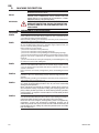
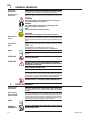
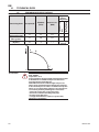
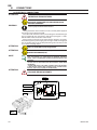
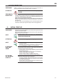
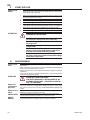
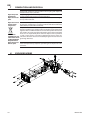
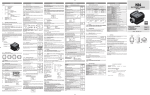
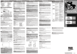
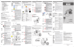
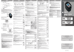
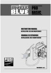
EX 50 12V
M0217ITEN rev 00
A
TABLE OF CONTENTS
EN
A
TABLE OF CONTENTS19
B MACHINE AND MANUFACTURER IDENTIFICATION
20
C
CONFORMITY21
C1
DECLARATION OF CONFORMITY (94/9/CE, Annex X, lett. B)
21
C2 DECLARATION OF INCORPORATION OF PARTLY-COMPLETED MACHINERY
21
D
MACHINE DESCRIPTION22
D1 DEFINITION OF CLASSIFIED ZONES 22
D2 INTENDED USE23
D3 HANDLING AND TRANSPORT23
E
GENERAL WARNINGS24
F
FIRST AID RULES24
G
GENERAL SAFETY RULES25
H
TECHNICAL DATA26
H1PERFORMANCE SPECIFICATIONS26
I
ELECTRICAL DATA27
L
OPERATING CONDITIONS27
L1ENVIRONMENTAL CONDITIONS27
L2ELECTRICAL POWER SUPPLY27
L3DUTY CYCLE28
L.4FLUIDS PERMITTED 28
M
INSTALLATION28
M1
POSITIONING, CONFIGURATIONS AND ACCESSORIES
29
M2
NOTES ON SUCTION AND DELIVERY LINES
29
N
CONNECTIONS30
N1ELECTRICAL CONNECTIONS30
N2PIPING CONNECTIONS31
O
INITIAL START-UP31
P
EVERY DAY USE32
Q
MAINTENANCE32
R
NOISE LEVEL33
S
PROBLEMS AND SOLUTIONS33
T
DEMOLITION AND DISPOSAL34
U
EXPLODED VIEWS34
M0217 EN
19
EN
B
MACHINE AND MANUFACTURER IDENTIFICATION
AVAILABLE MODELS: MANUFACTURER:
12V dc
PIUSI S.p.A. ,
Via Pacinotti 16/A – z.i. Rangavino
46029 Suzzara - Mantova (Italy)
20
M0217 EN
C
EN
CONFORMITY
C1 DECLARATION OF CONFORMITY (94/9/CE, Annex X, lett. B)
The manufacturer:
PIUSI S.p.A.
Via Pacinotti, 16/A
46029 Suzzara (MN) Italy
Declares under its own responsibility that the machine:
Type:
Pump
Model:
12 V
Year of manufacture: refer to the year of production shown on the CE plate affixed to the product.
Tech. Ref. FileAd20_949.01.00
Notified body data: name, identification number and address
·1 Name: CESI S.p.A.
·2
Identification number: 0722
·3
Address: Via Rubattino, 134 - 20134 (Milano)
Number of the EC type-examination certificate: CESI 12 ATEX 033X comply with all relevant provisions of the following directives:
-94/9/CE
and the following harmonized standards, applied standards and/or technical specifications:
UNI EN 1127-1:2008;
UNI EN 13463-1:2010;
CEI EN 60079-0:2009;
CEI EN 60079-1:2007
This equipment is classified as follows:
Group II, category 2 G Ex d IIA T = 135° C (T4)
Read the Use and Maintenance manual before using the pump..
Place: Suzzara (Mn)
Date: 22/02/2012
Legal Representative
C2 DECLARATION OF INCORPORATION OF PARTLY-COMPLETED MACHINERY
The undersigned
PIUSI S.p.A
Via Pacinotti 16/A- z.i.Rangavino
46029 Suzzara - Mantova - Italy
HEREBY STATES under its own responsibility, that the partly-completed machinery:
Description: Pump designed for the transfer of FUEL
Model: PUMP WITH ANTI-EXPLOSIVE HOUSING PROTECTION SYTEM
Serial No.: refer to Lot Number shown on CE plate affixed to product
Year of manufacture: refer to the year of production shown on the CE plate affixed to the product.
Is intended to be incorporated in a machine (or to be with other machines) so as to create
a machine to which applies Machine Directive 2006/42/EC, may not be brought into service
before the machine into which it is to be incorporated has been declared in conformity with
the provisions of the directive 2006/42/EC.
Is in conformity with the legal provisions indicated in the directives:
- Machine Directive 2006/42/EC
- Electromagnetic Compatibility Directive 2004/108/EC
To which the essential safety requirements have been applied and complied with
what indicated on annex I of the machine directive applicable to the product and shown below: 1.1.3 - 1.1.5 - 1.3.1 - 1.3.2 - 1.3.3 - 1.3.4 - 1.3.7 - 1.3.8 - 1.4.1 - 1.4.2.1 - 1.5.1 - 1.5.2 - 1.5.4 - 1.5.5
- 1.5.8 - 1.5.9 - 1.5.11 - 1.5.13 - 1.5.15 - 1.6.1 - 1.6.3 - 1.6.4 - 1.7.1 - 1.7.2 - 1.7.3 - 1.7.4.
The documentation is at the disposal of the competent authority following motivated request
at Piusi S.p.A. or following request sent to the email address: [email protected]
The person authorised to compile the technical file and draw up the declaration is Otto Varini
as legal representative.
Suzzara, 22/02/2012 Legal Representative
M0217 EN
21
EN
D
MACHINE DESCRIPTION
PUMP
MOTOR
ATTENTION
SELF-PRIMING, VOLUMETRIC, ROTATING ELECTRIC VANE PUMP,
EQUIPPED WITH BY-PASS VALVE.
BRUSH MOTOR POWERED BY CONTINUOUS CURRENT, LOW
VOLTAGE, WITH INTERMITTENT CYCLE, CLOSED TYPE, IP55
PROTECTION CLASS ACCORDING TO CEI EN 60034-5, FLANGEMOUNTED DIRECTLY TO THE PUMP BODY.
MOTOR EQUIPPED WITH AUTOMATIC THERMAL
OVERLOAD PROTECTION. SHOULD THE PROTECTION
ACTIVATE, TURN OFF THE PUMP AND WAIT FOR IT TO
COOL DOWN.
D1 DEFINITION OF CLASSIFIED ZONES
Definition of zones as shown in UNI EN 1127-1 standard
FOREWORD
Place where an explosive atmosphere made up of a mix of air and inflamZONE 0
ZONE 1
ZONE 2
ZONE 20
ZONE 21
ZONE 22
mable substances in the form of gas, vapour or mist is continuously present, either for long periods or frequently.
Note: Generally speaking, said conditions, when they occur, involve the inside of tanks, pipes and containers, etc.
Place where it is probable that an explosive atmosphere, made up of a mix
of air and inflammable substances in the form of gas, vapour or mist, can
occur occasionally during normal operation.
Note: Said zone can also include:
- places in the immediate vicinity of zone 0;
- places in the immediate vicinity of supply openings;
- places in the immediate vicinity of filling and and emptying openings;
- places in the immediate vicinity of appliances, protection systems and fragile glass and ceramic components, or components made of other similar
materials;
- places in the immediate vicinity of inadequately sealed stuffing boxes, e.g.,
on pumps and valves with stuffing box.
Place where it is improbable that an explosive atmosphere, made up of a
mix of air and inflammable substances in the form of gas, vapour or mist,
can occur during normal operation, but which, if it does occurs, only persists for a short time.
Note: Said zone can include, among others, places surrounding the zones
0 or 1.
Place where an explosive atmosphere in the form of a cloud of combustible
powders in the air is continuously present, either for long periods or frequently.
Note: Generally speaking, said conditions, when they occur, involve the inside of tanks, pipes and containers, etc.
Place where it is probable that an explosive atmosphere, in the form
of a cloud of combustible powders in the air, can occur occasionally
during normal operation.
Note: Said zone can include, for example, among others, places in
the immediate vicinity of powder loading and emptying points and
places where powder layers form or which, during normal operation,
could produce an explosive concentration of combustible powders
mixed with the air.
Place where it is improbable that an explosive atmosphere, in the form
of a cloud of combustible powders in the air, occur during normal operation but which, if it does occur, only persists for a short time.
Note: This zone can comprise, among others, places near appliances,
protections systems and components containing powder, out of
which the powder can come out due to leaks with the formation of
powder deposits (e.g., milling salt, where the powder comes out of the
mills and deposits).
22
M0217 EN
EN
D2 INTENDED
USE
INTENDED USE
PUMP FOR TRANFERRING FUEL SUITABLE FOR OPERATING IN
ZONES CLASSIFIED“1”AND “2”, ACCORDING TO DIRECTIVE 94/9/
CE
Using the appliance for fluids other than those listed at paragraph “L4 – Fluids permitted” and for uses other than those described at the item “authorised use” is forbidden.
FORBIDDEN
USE
PLANT OPERATION RESTRICTIONS
IT IS FORBIDDEN:
1 To use the appliance in a construction configuration other than
2
3
4
5
6
D3 that contemplated by the manufacturer
To use the appliance with fixed guards tampered with or removed.
To use the appliance in places where there is risk of explosion
and/or fires classified in the following zones:
0; 20; 21; 22
To integrate other systems and/or equipment not considered by
the manufacturer in the executive project.
To connect the appliance up to energy sources other than those
contemplated by the manufacturer
To use the commercial devices for purposes other than those
indicated by the manufacturer.
HANDLING AND TRANSPORT
Due to the limited weight and dimensions of the pumps, special lifting equipment is not required to handle them. The pumps are carefully packed before dispatch. Check the packing when
receiving the material and store in a dry place.
M0217 EN
23
EN
E
GENERAL WARNINGS
Important
precautions
Symbols used in
the manual
To ensure operator safety and to protect the pump from potential damage, workers must be fully acquainted with this
instruction manual before performing any operation.
The following symbols will be used throughout the manual to
highlight safety information and precautions of particular importance:
ATTENTION
This symbol indicates safe working practices for operators
and/or potentially exposed persons.
WARNING
This symbol indicates that there is risk of damage to the
equipment and/or its components.
NOTE
This symbol indicates useful information.
ATTENTION
Important note for guaranteed safety in classified zones
Manual preservation
Reproduction
rights
NOTE
This manual should be complete and legible throughout.
It should remain available to end users and specialist installation and maintenance technicians for consultation at any
time.
All reproduction rights are reserved by Piusi S.p.A. The text
cannot be reprinted without the written permission of Piusi
S.p.A.
© Piusi S.p.A.
THIS MANUAL IS THE PROPERTY OF Piusi S.p.A.
ANY REPRODUCTION, EVEN PARTIAL, IS FORBIDDEN.
THIS MANUAL IS VALID ONLY FOR DC PUMPS
ALWAYS USE THE RIGHT VOLTAGES TO CONNECT THE
PUMPS
ATTENTION
PUMP CANNOT BE USED FOR REFUELLING AIRCRAFTS
SUPPLIED BY AVGAS
ATTENTION
USE THE PUMP ONLY WITH FLUIDS PERMITTED.
DO NOT USE WITH FLUIDS NOT PERMITTED TO AVOID
DAMAGING THE PUMP. THE GUARANTEE LAPSES IN CASE
OF MISUSE OF THE FLUID.
DO NOT USE THE PUMP WITH LIQUID FOOD PRODUCTS
AND/OR WATER-BASED FLUIDS.
DO NOT OPERATE THE PUMP DRY TO AVOID DAMAGE.
Before connection, make sure that the piping and the suction
tank are free of dirt and solid residue that could damage the
pump and its accessories. NEVER COLLECT THE FLUID FROM THE
BOTTOM OF THE TANK SINCE IT MAY CONTAIN IMPURITIES
BEFORE USING THE PUMP SWITCH OFF ALL THE ELECTRONIC DEVICES ( I.E. MOBILE PHONES, BEEPERS ETC.)
F
FIRST AID RULES
Contact with
the product
Persons who
have suffered
electric shock
NOTE
SMOKING
PROHIBITED
In the event of problems developing following EYE/SKIN
CONTACT, INHALATION or INGESTION of the treated product, please refer to the SAFETY DATA SHEET of the fluid
handled.
Disconnect the power source, or use a dry insulator to protect yourself while you move the injured person away from
any electrical conductor. Avoid touching the injured person
with your bare hands until he is far away from any conductor. Immediately call for help from qualified and trained personnel. Do not operate switches with wet hands.
Please refer to the safety data sheet for the product
DO NOT SMOKE NEAR THE PUMP AND DO NOT USE THE
PUMP NEAR FLAMES.
24
M0217 EN
G
EN
GENERAL SAFETY RULES
USER'S
RESPONSIBILITY
Essential
protective
equipment
characteristics
Personal
protective
equipment
that must be
worn
IT IS ESSENTIAL TO GET TO KNOW AND UNDERSTAND
THE INFORMATION CONTAINED IN THIS MANUAL.
IT IS ESSENTIAL TO GET TO KNOW AND OBSERVE THE
SAFETY SPECIFICATIONS FOR FLAMMABLE LIQUIDS.
BEFORE USING THE PUMP IT’S IMPORTANT TO TRAIN
OPERATORS, INSTALLERS AND MAINTENANCE STAFF
TO LET THEM WORK IN A PARTICULAR AREA NO. 1 AS
MENTIONED BY DIRECTIVE 94/9/EC
IN CASE OF CONTACT WITH THE PRODUCT AND FOR GOOD
STANDARD OF BEHAVIOUR, wear protective equipment
which is:
• suited to the operations that need to be performed;
• resistant to products used
TO DO SO, PLEASE REFER TO THE RELEVANT TECHCNICAL
DATASHEETS OF THE FLUID USED.
safety shoes
close-fitting clothing
protection gloves
safety goggles
Necessary
safety
devices
instructions manual
Protective
gloves
Prolonged contact with the treated product may cause skin
irritation; always wear protective gloves during dispensing.
NOTE
TO PREVENT ELECTRIC SHOCK AND DETONATION OF
SPARKS, ALL PUMPING SYSTEM MUST HAVE PROPER
GROUNDING, INCLUDING TANK AND ANY ACCESSORIES.
DANGER
ATTENTION
ATTENTION
NOTE
ATTENTION
ATTENTION
M0217 EN
ENFORCE REGULATIONS FOR ELECTRICAL INSTALLATION
ALL WIRING AND ELECTRICAL CONNECTIONS MUST
BE PERFORMED BY AUTHORIZED AND SUITABLY
TRAINED PERSONNEL.
Never touch the electric plug or socket with wet hands.
Do not switch the dispensing system on if the network
connection cable or important parts of the apparatus
are damaged, such as the inlet/outlet pipe, nozzle or
safety devices. Replace the damaged pipe immediately.
The electrical connection between the plug and
socket must be kept well away from water.
THE PUMP IS EQUIPPED WITH CURRENT-SENSING
PROTECTION. IF IT ACTIVATES TURN OFF THE PUMP
IMMEDIATELY.
THE PUMP IS EQUIPPED WITH PROTECTION AGAINST
OVERHEATING AND OVERLOAD RISKS. SHOULD SUCH
DEVICES ACTIVATE, THE PUMP SHUTS DOWN AUTOMATICALLY, BUT THE MASTER SWITCH IS NOT TURNED
OFF. IT IS IMPORTANT TO STOP THE PUMP USING ITS
SWITCH. THE PUMP RESTARTS AFTER
ITS NORMAL OPERATING CONDITIONS HAVE BEEN
RESTORED.
FAILURE TO OBSERVE THE ABOVE MENTIONED RULES
CAN CAUSE SERIOUS ACCIDENTS
SHOULD THE HEAT SENSOR ACTIVATE UNDER
NORMAL USE CONDITIONS, PLEASE CONTACT THE
TECHNICAL SUPPORT.
25
EN
H
TECHNICAL DATA
H1
PERFORMANCE SPECIFICATIONS
The performance diagram shows flow rate as a function of back pressure.
Flow Rate
(l/min)
Back Pressure
4 meters of 3/4”
tube
automatic dispensing nozzle
Typical
delivery
configuration
15
52
0,2
17
40
0,5
•
•
1,1
Delivery
Closed
Functioning Point Absorption(A)
A
(Maximum Flow Rate)
B
(Base system)
C
(By-Pass)
24
(BAR)
0
Y
A
B
C
0
ATTENTION
P (bar)
X
The curve refers to the following operating conditions:
Fluid: PETROL,
Temperature: 20° C
Suction conditions: The pipe and the pump position relative
to the fluid level is such that a low pressure of 0.3 bar is
generated at the nominal flow rate.
Under different suction conditions higher low pressure
values can be created that reduce the flow rate compared
to the same back pressure values. To obtain the best performance, it is very important to reduce loss of suction pressure as much as possible by following these instructions:
• shorten the suction pipe as much as possible
• avoid useless elbows or throttling in the pipes
• keep the suction filter clean
• use a pipe with a diameter equal to, or greater than,
indicated (see Installation).
26
M0217 EN
I
EN
ELECTRICAL DATA
PUMP MODEL
12V
POWER SUPPLY
Voltage (V)
Frequency (Hz)
12
DC
CURRENT
Max (*) (A)
25
(*) Refers to functioning in by-pass mode.
POWER CORD INLET
L
1/2” NPT
OPERATING CONDITIONS
L1
AMBIENT
TEMPERATURE
FLUID
TEMPERATURE
RELATIVE HUMIDITY
LIGHTING
ATTENTION
L2
NOTE
ATTENTION
M0217 EN
ENVIRONMENTAL CONDITIONS
min. +23 °F / max +104 °F
min. -10 °C / max +40 °C
min. +23 °F / max +104 °F
min. -10 °C / max +40 °C
max. 90%
The environment must conform to directive 89/654/EEC on
work environments.
In case of non-EU countries, refer to directive EN ISO 12100-2
§ 4.8.6.
The temperature limits shown apply to the pump components and must be respected to avoid possible damage or
malfunction.
ELECTRICAL POWER SUPPLY
The pump must be powered by DC line, the nominal values of
which are indicated on the table in the paragraph "I - ELECTRICAL DATA".
The maximum acceptable variations from the electrical parameters are:
Voltage: +/- 5% of the nominal value
Power supply from lines with values that do not fall within
the indicated limits could cause damage to the ELECTRICAL
AND electronic components.
27
EN
L3
DUTY CYCLE
NOTE
The pumps have been designed for intermittent use and
a duty cycle of 30 min. ON and 60 min. OFF in conditions of
maximum A. TEMPERATURE (40 °C) AND AT NOMINAL TRANSFER CONDITIONS.
Functioning under by-pass conditions is only allowed for
short periods of time (max. 3 minutes).
ATTENTION
L.4 FLUIDS PERMITTED
ATTENTION
THE PUMP CAN BE UESED ONLY WITH THE FOLLOWING FLUIDS:
- DIESEL - KEROSENE
- PETROL - PETROL ALCOHOL MIXED MAX 15%
MINSTALLATION
ATTENTION
PRELIMINARY
INSPECTION
BEFORE ANY OPERATION, ENSURE TO BE OUT OF
POTENTIALLY EXPLOSIVE AREAS
-
-
-
-
ATTENTION
ATTENTION
-
The pump must never be operated before the delivery and
suction lines have been connected.
TIGHTEN THE ELECTRICAL BOX TO ENSURE PROTECTION
AGAINST THE RISK OF EXPLOSION
THE RIGHT CLAMPING SCREWS COUPLE THAT GRANTS THIS
PROTECTION IS 10Nm
Verify that all components are present. Request any missing parts
from the manufacturer.
Check that the pump has not suffered any damage during transport
or storage.
Carefully clean the suction and delivery inlets and outlets, removing
any dust or other packaging material that may be present.
Check that the electrical data corresponds to those indicated on the
data plate.
Install the pump at a height of min. 80 cm.
IF VALVES IN THE CIRCUIT ARE TO BE INSTALLED, MAKE
SURE THEY ARE EQUIPPED WITH OVERPRESSURE SYSTEM.
CLEAN THE TANK AND MAKE SURE IT IS WELLVENTILATED (RECOMMENDED OPENING
PRESSURE: 3 psi)
APPLY THE QUICK COUPLING TO THE TANK CORRECTLY
AND SAFELY DO NOT BLOCK THE DRAINAGE HOLES
28
M0217 EN
EN
M1POSITIONING, CONFIGURATIONS AND ACCESSORIES
NOTE
The pump must be secured in a stable manner.
ATTENTION
It is the installer's responsibility to provide the line accessories necessary for the safe and proper functioning of the
pump. The accessories that are not suitable to be used with
the previously indicated material could damage the pump
and/or cause injury to persons, as well as causing pollution.
To maximise performance and prevent damage that could
affect pump operation, always demand original accessories.
M2NOTES ON SUCTION AND DELIVERY LINES
DELIVERY
The selection of the pump model must be made taking into account the characteristics of
the system.
The combination OF: the length of the pipe, the diameter of the pipe, as well as the accessories
installed, could create back pressure that are greater than the maximum predicted pressure,
thereby causing the pump's electronic controls to intervene and reducing the dispensed flow
considerably.
In these cases, to guarantee correct operation of the pump, it is necessary to reduce the resistance of the system using pipes that are shorter or that have a greater diameter, as well as
line accessories with smaller resistances (e.g. an automatic dispensing nozzle with greater flow
rate capacity).
SUCTION
FOREWORD
Self-priming pumps are characterized by excellent suction capacity.
During the start-up phase, when the suction pipe is empty and the pump is wet with the fluid,
the electric pump unit is able to suck liquid from a maximum vertical distance of 2m.
It is important to note that it could take up to 1 minute for the pump to prime and that the
presence of an automatic dispensing nozzle on the delivery side will prevent the air trapped
during the installation from being released and, therefore, the correct priming of the pump.
For this reason, it is always advisable to prime the pump without an automatic delivery nozzle,
verifying the proper wetting of the pump.
Always install a foot valve to prevent the suction pipe from being emptied and to keep the
pump wet at all times. In this way, the pump will always start up immediately the next times it
is used. When the system is in operation, the pump can operate with back pressures of up to
0.5 bars on the suction inlet; beyond this point, the pump may begin to cavitate resulting in a
drop of the flow rate and an increase in the noise levels of the system.
In light of this, it is important to guarantee small back pressures on the suction side, by using
short pipes with diameters that are equal to or larger than those recommended, reducing bends to a minimum, and using filters with a large cross-section and foot valves with minimum
possible resistance on the suction side. It is very important to keep the suction filters clean
because, when they become clogged, they increase the resistance of the system.
The vertical distance between the pump and the fluid must be kept as short as possible, and
it must fall within the 2m maximum required for priming. If the distance is greater, a foot valve
must be installed to allow the suction pipes to fill up and the diameter pipes must be larger. It is
however recommended that pump not be installed if the vertical distance is greater than 3m.
ATTENTION
M0217 EN
If the suction tank is higher than the pump, an
anti-siphon valve should be installed to prevent accidental diesel fuel leaks. Dimension the installation
in order to control the back pressures due to water
hammering
It is a good system practice to install vacuum and
air pressure gauges right at the inlets and outlets of
the pump, which allow verification that operating
conditions are within anticipated limits. To prevent
the suction pipes from being emptied when the pump
stops, a foot valve should be installed.
THE INSTALLER IS RECOMMENDED TO INSTALL A
SUCTION FILTER.
29
EN
NCONNECTIONS
N1 ELECTRICAL CONNECTIONS
BEFORE ANY OPERATION, ENSURE TO BE OUT OF
POTENTIALLY EXPLOSIVE AREAS
ATTENTION
IT IS THE INSTALLER'S RESPONSIBILITY TO CARRY OUT THE
ELECTRICAL CONNECTIONS IN COMPLIANCE WITH THE
RELEVANT STANDARDS.
WARNING
ATTENTION
Comply with the following (not exhaustive) instructions to
ensure a proper electrical connection:
- During installation and maintenance make sure that power supply to
the electric lines has been turned off.
- Use cables with minimum sections, rated voltages and installation type
that are suitable for the characteristics indicated in paragraph "I - ELECTRICAL DATA" and the installation environment.
- Always make sure that the cover of the terminal strip box is closed before switching on the power supply, after having checked the integrity of
the seal gaskets that ensure the IP55 protection grade. For those screws
use a 10 nm clamping couple
All motors are equipped with a grounding terminal.
Make sure all the plant is properly grounded.
ATTENTION
BE SURE TO USE A CABLE GLAND, WITH SUFFICIENT
PROTECTION GRADE (Exd)
NOTE
IN THE EVENT OF INSTALLATION IN ZONES WHICH ARE
NOT CLASSIFIED, IT IS SUFFICIENT TO OBSERVE THE MINIMUM SAFETY STANDARDS ALREADY MENTIONED IN THIS
MANUAL.
- THE OWNER HAS THE RESPONSIBILITY TO VERIFY THAT
ALL THE LOCAL AND NATIONAL REGULATIONS HAVE BEEN
OBSERVED.
- MAKE SURE THAT THE CABLE CONNECTING THE BATTERY
IS PROTECTED FROM HEAT SOURCES AND SHARP EDGES.
INSTALL THE FUSE CLOSER TO THE BATTERY.
ATTENTION
FAILURE TO OBSERVE THE ABOVE MENTIONED RULES
CAN CAUSE SERIOUS ACCIDENTS
Switch
Red Cable +
Black Cable t°C
GND
Motor
protector
1/2” NPT
INLET
30
M0217 EN
EN
N2 PIPING CONNECTIONS
FOREWORD
ATTENTION
- Before carrying out any connection, refer to the visual indications i.e.
arrow on the pump head, to identify suction and delivery.
Wrong connection can cause serious pump
damage.
PRELIMINARY - Before connection, make sure that the piping and the suction tank
are free of dirt and solid residue that could damage the pump and its
INSPECTION
accessories. NEVER COLLECT THE FLUID FROM THE BOTTOM OF THE
TANK SINCE IT MAY CONTAIN IMPURITIES
- Before connecting the delivery pipe, partially fill the pump body, from
delivery side, with the liquid that needs to be pumped in order to facilitate priming.
- Do not use conical threaded fittings, which could damage the threaded inlet or outlet openings of the pump if excessively tightened.
O
INITIAL START-UP
FOREWORD
NOTE
- Check that the quantity of fluid in the suction tank is greater than the
amount you wish to transfer.
- Make sure that the residual capacity of the delivery tank is greater than
the quantity you wish to transfer.
- Make sure that the piping and line accessories are in good condition.
THIS PUMP IS NOT PROVIDED FOR FURTHER REGULATION
OF DELIVERY AND PRESSURE
ATTENTION
Fluid leaks can damage objects and injure persons.
NOTE
- Never start or stop the pump by connecting or cutting out
the power supply.
- Prolonged contact with some fluids can damage the skin.
The use of goggles and gloves is recommended.
Depending on the system characteristics, the priming phase
can last from several seconds to a few minutes. If this phase is
prolonged, stop the pump and verify:
- that the pump is not running completely dry (fill with fluid
from the delivery line);
- that the suction pipe guarantees against air infiltration;
- that the suction filter is not clogged;
- that the suction height is not higher than 2 mt.
- that all air has been released from the delivery pipe.
When priming has occurred, verify that the pump is operating
within the anticipated range, in particular:
- that under conditions of maximum back pressure, the power absorption of the motor stays within the values shown
on the identification plate;
- that the delivery back pressure does not exceed the maximum back pressure for the pump.
IF THE PUMP
DOES NOT
PRIME
AT THE END
OF THE INITIAL
START-UP
M0217 EN
31
EN
P
EVERY DAY USE
USE PROCEDURE
1
If flexible pipes are used, attach the ends of the piping to the tanks.
In the absence of an appropriate slot, solidly grasp the delivery pipe
before beginning dispensing.
2
Before starting the pump make sure that the delivery valve is closed
(dispensing nozzle or line valve)
Turn the ON/OFF switch on
Open the delivery valve, solidly grasping the pipe
While dispensing, do not inhale the pumped product
IF ANY TREATED FLUID LEAKS OUT DURING DISPENSING, TAKE ALL
STEPS NECESSARY TO ENSURE THE LEAKED FLUID IS CLEANED UP
AND SAFE AS SPECIFIED ON THE PRODUCT TECHNICAL SHEET.
Close the delivery valve to stop dispensing
When dispensing is finished, turn off the pump
3
4
5
6
7
8
ATTENTION
THE WORKING OPERATIONS MUST ALWAYS BE
GUARDED BY THE OPERATOR.
The by-pass valve allows functioning with delivery
closed only for short periods (max. 3 minutes).
To avoid damaging the pump, after use, make sure
the pump is off.
In case of a power break, switch the pump off
straight away.
Should any sealants be used on the suction and
delivery circuit of the pump, make sure that these
products are not released inside the pump.
Foreign bodies in the suction and delivery circuit of
the pump could cause malfunctioning and breakage
of the pump components.
QMAINTENANCE
Safety instructions
ATTENTION
Authorised
maintenance
personnel
Measures to be
taken
ONCE A WEEK:
ONCE A
MONTH:
The PUMP IS DESIGNED AND CONSTRUCTED TO require a minimum of
maintenance.
Before carrying out any maintenance work, DISCONNECT THE PUMP from
any electrical and hydraulic power source.
During maintenance, the use of personal protective equipment (PPE) is
compulsory.
In any case always bear in mind the following basic recommendations for
a good functioning of the pump
BEFORE ANY OPERATION, ENSURE TO BE OUT OF
POTENTIALLY EXPLOSIVE AREAS
FOR SAFETY REASONS IT’S NOT ALLOWED TO DISASSEMBLE THESE PARTS : (1) BOTTOM (2) MOTOR
PIPE (3) PUMP BODY
All maintenance must be performed by qualified personnel. Tampering
can lead to performance degradation, danger to persons and/or property and may result in the warranty and UL/ATEX CERTIFICATION being
voided.
Check that the labels and plates found on the dispensing system do not
deteriorate or become detached over time.
- Check that the pipe connections are not loose to prevent any leaks;
- Check and keep the filter installed on the suction line clean.
- Check the pump body and keep it clean and free of any impurities;
- Check that the electrical supply cables are in good condition.
32
M0217 EN
EN
R
NOISE LEVEL
S
PROBLEMS AND SOLUTIONS
Under normal operating conditions, noise emission of all models does not exceed
74 dB at a distance of 1 metre from the electric pump.
For any problems contact the authorised dealer nearest to you.
PROBLEM
POSSIBLE CAUSE
Lack of electric power
THE MOTOR IS NOT
TURNING
Rotor jammed
THE MOTOR TURNS
SLOWLY WHEN STARTING
Motor problems
Low voltage in the electric
power line
CORRECTIVE ACTION
Check the electrical connections
and the safety systems.
Check for possible damage
or obstruction of the rotating
components.
Contact the Service Department
Bring the voltage back within
the anticipated limits
Refill the tank
Clean and/or replace the valve
Clean the filter
Lower the pump with respect to
the level of the tank or increase
the cross-section of the piping
High loss of head in the delivery Use shorter piping or of greater
circuit (working with the by-pass diameter
open)
Dismantle the valve, clean and/
LOW OR NO FLOW RATE By-pass valve blocked
or replace it
Air entering the pump or the
Check the seals of the connecsuction piping
tions
A narrowing in the suction
Use piping suitable for working
piping
under suction pressure
Low rotation speed
Check the voltage at the pump.
Adjust the voltage and/or use
cables of greater cross-section
The suction piping is resting on Raise the piping
the bottom of the tank
Cavitation occurring
Reduce suction pressure
INCREASED PUMP
Irregular functioning of the
Dispense until the air is purged
NOISE
by-pass
from the by-pass system
Presence of air in the fluid
Verify the suction connections
LEAKAGE FROM THE
Seal damaged
Check and replace the seal
PUMP BODY
Suction circuit blocked
Remove the blockage from the
suction circuit
Malfunction of foot valve fitted Replace foot valve
on suction circuit
THE PUMP DOES NOT
PRIME THE LIQUID
The suction chambers are dry
Add liquid from pump delivery
side
The pump chambers are dirty
Remove the blockages from the
or blocked
suction and delivery valves
THE HEAT SENSOR
Operating fault
Contact the technical support..
ACTIVATES UNDER
NORMAL OPERATING
CONDITIONS
M0217 EN
Low level in the suction tank
Foot valve blocked
Filter clogged
Excessive suction pressure
33
EN
T
DEMOLITION AND DISPOSAL
Foreword
Disposal of packing material
Disposal of metal
parts
If the system needs to be disposed, the parts which make it up must be
delivered to companies that specialize in the recycling and disposal of
industrial waste and, in particular:
The packaging consists of biodegradable cardboard which can be delivered to companies for normal recycling of cellulose.
Metal parts, whether paint-finished or in stainless steel, can be consigned
to scrap metal collectors.
Disposal of electric These must be disposed of by companies that specialize in the disposal
and electronic
of electronic components, in accordance with the indications of directive
components
2002/96/CE (see text of directive below).
European Directive 2002/96/EC requires that all equipment marked
with this symbol on the product and/or packaging not be disposed of
together with non-differentiated urban waste. The symbol indicates that
this product must not be disposed of together with normal household
waste. It is the responsibility of the owner to dispose of these products
Information
as well as other electric or electronic equipment by means of the speregarding the envi- cific refuse collection structures indicated by the government or the local
ronment for clients governing authorities.
residing within the
European Union
Disposal of miscel- Other components, such as pipes, rubber gaskets, plastic parts and wires,
laneous parts
must be disposed of by companies specialising in the disposal of industrial waste.
U
EXPLODED VIEWS
1
2
3
34
M0217 EN
Piusi S.p.A
46029 Suzzara (Mantova) Italy
www.piusi.com
The Company reserves the right to modify the information contained in this user manual without any prior notice
M0217ITEN rev 00