1
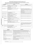
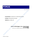
6
CONVERTITORI DI SEGNALE
SIGNAL CONVERTERS
CATALOGHI EUROTEK - EUROTEK's CATALOGUE
2
ALIMENTATORI
POWER SUPPLY
1
MODULI INTERFACCIA
INTERFACE MODULES
2
MODULI COMPATTI BX/SNR
COMPACT MODULES BX/SNR
3
MODULI INTERFACCIA STATICI - UNITA' STATICHE DI POTENZA
STATIC INTERFACE MODULES - STATIC POWER UNITS
4
FILTRI DI RETE
LINE FILTERS
5
CONVERTITORI DI SEGNALE
SIGNAL CONVERTERS
6
INDICE - INDEX
CONVERTITORI ETK-MT3
ETK-MT3 CONVERTERS
descrizione generale e dimensioni
dati tecnici
schemi di collegamento
general description and dimensions
technical data
connection diagrams
P.
P.
P.
P.
4
5
6
7
KIT DI PROGRAMMAZIONE PER CONVERTITORI ETK-MT3
CONFIGURATION KIT FOR ETK-MT3 CONVERTERS
P. 8
ACCESSORI PER CONVERTITORI ETK-MT3
ACCESSORIES FOR ETK-MT3 CONVERTERS
descrizione generale e "come ordinare"
dati tecnici e dimensioni
schemi di collegamento
esempi di applicazione
P.
P.
P.
P.
CONVERTITORI SERIALI
SERIAL CONVERTERS
general description and "how to order"
technical data and dimensions
connection diagram
application examples
9
10
11
12
P. 13 - 15
3
Convertitori ETK-MT3
ETK-MT3 converters
INDICE - INDEX
4
CONVERTITORI ETK-MT3
descrizione generale e dimensioni
dati tecnici
schemi di collegamento
ETK-MT3 CONVERTERS
general description and dimensions
technical data
diagram connection
P.
P.
P.
P.
4
5
6
7
KIT DI PROGRAMMAZIONE PER CONVERTITORI ETK-MT3
CONFIGURATION KIT FOR ETK-MT3 CONVERTERS
P. 8
ACCESSORI PER CONVERTITORI ETK-MT3
descrizione generale e "come ordinare"
dati tecnici e dimensioni
schemi di collegamento
esempi di applicazione
ACCESSORIES FOR ETK-MT3 CONVERTERS
general description and "how to order"
technical data and dimensions
diagram connection
application examples
P.
P.
P.
P.
9
10
11
12
CONVERTITORE / ISOLATORE / UNITA' DI ALLARME ETK-MT3
SIGNAL CONVERTER / INSULATOR / ALARM UNIT ETK-MT3
Modulo intelligente a microprocessore con ingresso da sensori di temperatura e altri
segnali analogici. ETK-MT3 opera la conversione di un ingresso a basso livello in un
segnale normalizzato alto livello. Permette il condizionamento e/o la linearizzazione
del segnale. Garantisce una sicura separazione galvanica dal campo; consente di
impostare soglie di minimo o massimo sul valore misurato con uscita comune di allarme.
Microprocessor based module for temperature sensors and other analogue signals.
ETK-MT3 performs :
- conversion from low level signal input into high level standard output
- linearization and or modification of input value
- hi / lo alarm threshold with common output
Disponibili due modelli: uno liberamente configurabile da PC mediante software dedicato
l'altro a configurazione fissa, su richiesta specifica del cliente
Two models are available: free configurable
fix range on custom request
Elevata risoluzione / Calibrato automaticamente su tutti gli ingressi e campi scala
High resolution / Factory calibrate on all I/O types
Isolato galvanicamente su due vie: ingresso / uscita
Input / output galvanically insulated
Filtro digitale programmabile per attenuazione dei disturbi sull'ingresso
Digital programmable input filter for noise attenuation
Allarmi di minimo e massimo con uscita open collector
Hi / Lo alarm threshold - open collector output
Custodia in materiale autoestinguente UL 94-V0
UL 94-V0 selfextinguishing case
Protezione IP20 / esecuzione per aggancio su guida DIN
IP20 / DIN rail mounting enclosure
TIPO DI INGRESSO / INPUT TYPE
TERMORESISTENZA - RTD
Pt 100
3 / 4 fili wires
Ni 100
3 / 4 fili wires
TERMOCOPPIA - THERMOCOUPLE
B
E
J
K
N
R
S
T
CAMPO DI LAVORO / RANGE
MIN
MAX
MIN. SPAN
-190°C
-40°C
790°C
180°C
50°C
50°C
0°C
-270°C
-200°C
-260°C
-270°C
0°C
0°C
-270°C
1820°C
1000°C
960°C
1320°C
1300°C
1760°C
1760°C
400°C
50°C
100°C
100°C
100°C
100°C
250°C
250°C
50°C
TIPO DI USCITA / OUTPUT TYPE
TENSIONE - VOLTAGE
0 - 10Vdc
0 - 5Vdc
CORRENTE - CURRENT
0 - 20mA
4 - 20mA
DIMENSIONI - DIMENSIONS (mm)
90
12
M N
0mV
0V
1000mV
10V
50mV
1V
CORRENTE - CURRENT
mA
mA
0mA
0mA
20mA
50mA
10mA
10mA
POTENZIOMETRO - POTENTIOMETER
4 fili - 4 wires
0ohm
8000ohm
500ohm
111
O P
TENSIONE - VOLTAGE
mV
V
Q R
convertitore
converter
1
CONVERTITORE / ISOLATORE / UNITA' DI ALLARME ETK-MT3
SIGNAL CONVERTER / INSULATOR / ALARM UNIT ETK-MT3
CARATTERISTICHE TECNICHE - TECHNICAL SPECIFICATIONS
FILTRO DIGITALE D'INGRESSO (elevata attenuazione disturbi)
DIGITAL INPUT FILTER (high noise attenuation)
4 livelli configurabili: 5.24Hz - 6.55Hz - 26.2Hz - 52.4Hz
4 configurable levels : 5.24Hz - 6.55Hz - 26.2Hz - 52.4Hz
IMPEDENZA D'INGRESSO
INPUT IMPEDANCE
> 1 Mohm (input V)
> 10 Mohm (input mV)
> 10 ohm (input mA)
COMPENSAZIONE GIUNTO FREDDO (per termocoppie)
COLD JUNCTION COMPENSATION (for thermocouple)
0,5°C ± 0,05°C / °C
0,5°C ± 0,05°C / °C
SEGNALAZIONE INTERRUZIONE INGRESSO (Termocoppie - TR)
OPEN INPUT DETECTION (thermocouple - RTD)
L'uscita si porta al valore massimo +5%
Maximum output value +5%
CORRENTE AL SENSORE (TR, resistenza, potenziometro)
SENSOR CURRENT (RTD, resistance, potentiometer)
200µA (3 fili) - 400µA (4 fili)
200µA (3 wires) - 400µA (4 wires)
RESISTENZA CAVI SENSORI (TR, resistenza, potenziometro)
SENSOR WIRE RESISTANCE (RTD, resistance, potenziometer)
< 500 Ohm
RISOLUZIONE USCITA
OUTPUT RESOLUTION
Su 4000 punti
on 4000 points
RESISTENZA DI CARICO
LOAD RESISTANCE
>5000 Ohm per uscita in tensione (V, mV) - < 500 Ohm per uscita in corrente (mA)
>5000 Ohm for voltage output (V, mV) - < 500 Ohm for current output (mA)
ALLARMI*
ALARMS*
minimo e/o massimo configurabili da PC
high and/or low configurable by PC
USCITA ALLARME
ALARM OUTPUT
OPEN COLLECTOR (isolata 2500 Vrms)
OPEN COLLECTOR output (2500 Vrms insulation)
ISOLAMENTO INGRESSO / USCITA
INPUT / OUTPUT INSULATION
1500 Vrms 50 Hz / 1 min ( 4000V opzione - option )
TENSIONE DI ALIMENTAZIONE (con protezione inversione polarità)
VOLTAGE SUPPLY (With reverse polarity protection)
14 - 36 Vdc
ASSORBIMENTO DI CORRENTE
CURRENT CONSUMPTION
30mA
max. 30mA
PRECISIONE DI CALIBRAZIONE
CALIBRATION ACCURACY
0,2% v.f.s. - f.s.v.
TEMPO DI CAMPIONAMENTO
SAMPLING TIME
35 msec
TEMPO DI RISPOSTA**
RESPONSE TIME**
200 msec
TEMPERATURA DI LAVORO
WORKING TEMPERATURE
0 ~ +50°C
TEMPERATURE DI IMMAGAZZINAMENTO
STORAGE TEMPERATURE
-20 ~ +70°C
DERIVA TERMICA
THERMAL DRIFT
0,01% per tutta la scala
0,01% all along the range
LINEARITA'
LINEARITY
0,05% v.f.s. (0,1% per ingressi TC/TR)
0,05% f.s.v (0,1% TC/RTD input)
EMC EMISSIONI - EMISSION
EMC IMMUNITA' - IMMUNITY
EN 50081-2
EN 50082-2
NOTE:
* gli allarmi di minimo e massimo escono sugli stessi morsetti.
** in funzione del filtro programmato, tale valore può incrementare fino ad un massimo di 900msec.
2
NOTES:
* minimum and maximum alarms uses the same terminals.
** according to the selected input filter, the value could increase up to 900 msec.
CONVERTITORE / ISOLATORE / UNITA' DI ALLARME ETK-MT3
SIGNAL CONVERTER / INSULATOR / ALARM UNIT ETK-MT3
COLLEGAMENTI INGRESSO - INPUT CONNECTIONS
INGRESSO IN CORRENTE
CURRENT INPUT
INGRESSO IN TENSIONE max.10V
VOLTAGE INPUT max. 10V
+
+
I
L
I
POTENZIOMETRO
POTENTIOMETER
L
I
L
I
L
I
L
I
L
G H
G H
G H
G H
G H
G H
E F
E F
E F
E F
E F
E F
USCITA IN CORRENTE
CURRENT OUTPUT
0 ~ 20mA / 4 ~ 20mA
M N
+I
USCITA IN TENSIONE
VOLTAGE OUTPUT
0 ~ 10V / 0 ~ 5V
-V
+V
O P
Q R
Q R
TENSIONE CONTINUA 24Vcc
DIRECT CURRENT 24Vdc
RANGE 14 ~ 36Vdc
0V
M N
O P
ALIMENTAZIONE - SUPPLY
+
-
SUPPLY
M N
24V
O P
COLLEGAMENTO ALLARMI - ALARM CONNECTIONS
PNP
NPN
M N
-
- COM
R LOAD
Q R
+ COM
R LOAD
+
O P
Q R
-
RTD 3 FILI
RTD 3 WIRES
+
COLLEGAMENTI USCITA - OUTPUT CONNECTIONS
-I
TERMOCOPPIA
THERMOCOUPLE
+
INGRESSO IN TENSIONE max.1V
VOLTAGE INPUT max. 1V
+
M N
-
O P
Q R
+
+
SUPPLY
COME ORDINARE - HOW TO ORDER
Modello a configurazione fissa: ETK-MT3/ tipo di ingresso / tipo di uscita / range N. 8850 Fix range module, part number 8850:
Esempi:
Example:
- per ingresso da termocoppia tipo K, uscita in tensione 0 - 10Vdc e range di lavoro del - for a module with input from thermocouple type K, voltage output 0 ~ 10Vdc and sensor range
sensore da 0 a 600°C la sigla diventa: ETK-MT3/ Tc K / 0 - 10V / 0 - 600°C N.8850.
0 ~ 600°C the part number became: ETK-MT3/ Tc K / 0 - 10V / 0 - 600°C N.8850.
- nell'utilizzo come isolatore galvanico con ingresso in tensione 0 - 10Vdc e uscita in corrente
4 - 20mA la sigla diventa: ETK-MT3/ 0 - 10V / 4 - 20mA / 0 - 100% N.8850.
- for a module with voltage input 0 ~ 10Vdc and current output 4 ~ 20mA the part number
became: ETK-MT3/ 0 - 10V / 4 - 20mA / 0 - 100% N.8850.
Modello liberamente configurabile: ETK-MT3/FC N.8849
Free configurable model: ETK-MT3/FC N.8849
3
KIT DI PROGRAMMAZIONE PER ETK-MT3
ETK-MT3 CONFIGURATION KIT
DIPRO1 è un sistema completo di configurazione che consente la programmazione
di tutti i parametri funzionali del convertitore di segnale ETK-MT3 quali:
- tipo d'ingresso e relativo campo scala
- filtro digitale sull'ingresso
- tipo di uscita
- soglie di allarme.
Inoltre DIPRO1 prevede la possibilità di creare e memorizzare modelli contenenti
i dati di configurazione, che potranno essere utilizzati per la programmazione di
ulteriori moduli.
DIPRO1 is a software package for the configuration of all functional parameters
of ETK-MT3 signal converter as:
- input type and range
- digital input filter
- output type
- alarm thresholds.
Furthermore the software DIPRO1 offers configuration recipe storage and download
capability for fast setup of the modules.
Software di configurazione DIPRO1 - DIPRO1 configuration software
DIPRO1 è un software di semplice utilizzo che consente di configurare ogni
parametro funzionale dei convertitori di segnale (ETK-MT3/FC COD.8849)
liberamente configurabili mediante la compilazione guidata di 5 finestre.
1) INGRESSO:
selezione del tipo di sensore o della grandezza analogica che verrà collegata
ai morsetti di ingresso.
2) FILTRO INGRESSO:
Scelta del valore di attenuazione dei disturbi sul segnale d'ingresso.
L'impostazione del filtro non altera il valore del segnale misurato in ingresso.
NOTA: il filtro deve sempre essere impostato (default 52,4 Hz).
DIPRO1 is a software package dedicated to ETK-MT3 configuration.
Through 5 windows menù you can easily set up all ETK-MT3 parameters.
3) USCITA:
Scelta guidata del tipo (V o mA) e del valore del segnale di uscita tra quelli
evidenziati automaticamente.
4) ALLARMI:
Scelta del valore delle soglie di allarme minimo e massimo entro i limiti, del
campo scala impostato, evidenziati automaticamente.
5) GENERALE:
Salva modello Possibilità di creazione e memorizzazione delle ricette di
configurazione.
Carica modello Ricerca delle ricette memorizzate in archivio e caricamento
diretto sul modulo ETK-MT3.
Numero porta seriale Selezione della porta seriale utilizzata sul PC per il
collegamento di configurazione dei moduli ETK-MT3.
3) OUTPUT
Output type (V or mA) and value definition, within the standard automatically
displayed.
4) ALARMS:
Hi and / or Lo alarm threshold set-up, within the programmed range automatically
displayed.
5) GENERAL:
Recipe store Configuration recipe data storage
Recipe load Recipe searching and down loading
PC port number Selection of connection PC port for the configuration cable
Requisiti minimi di sistema - Minimum hardware requirements
PC IBM compatibile / processore 486 o superiore
IBM compatible PC / processor 486 or better
4 MB di RAM di sistema - 4 MB RAM memory
Scheda video VGA - VGA display
Sistema operativo Windows 95 e successive versioni*
Windows 95 operating system and following upgrading*
1) INPUT
Input type and selection range required.
2) INPUT FILTER
Filter selection Digital filter value definition in order to attenuate the noise on
the input signal. The filter does not effect the input signal measurement .
NOTE: the filter value must be always setted (default 52,4Hz).
Composizione della fornitura - Supplied parts
N°2 floppy disk per il software di configurazione - N°2 floppy disks for the configuration software
N°1 floppy disk contenente i driver per WIN 2000 e WIN NT
N°1 floppy disk with the drivers for WIN 2000 and WIN NT
N° 1 cavetto di connessione dalla porta seriale del PC al modulo
N° 1 PC / module connecting cable
N° 1 manuale di istruzioni - N° 1 instruction manual
COME ORDINARE - HOW TO ORDER
Sigla - Part number
DIPRO1
Descrizione - Description
software di configurazione completo di cavo per il collegamento al PC
configuration kit
NOTA: il software DIPRO1 effettua una comunicazione unidirezionale con il convertitore ETK-MT3/FC, da PC a modulo. Il messaggio di INVIO TERMINATO
corrisponde quindi al termine della trasmissione dei dati e non all'avvenuta recezione degli stessi da parte del convertitore.
NOTE: Comunication between DIPRO1 and PC is one way only. The message of "transmission ok" show the end of data transmission, not the reception
of data on ETK-MT3 memory.
4
21052 BUSTO ARSIZIO (VA) - Via Corta, 7-Tel. +39 0331.677196-679930 - Fax +39 0331.679940
E-mail: [email protected] - Web: www.eurotek.it
ALIMENTATORE E ATTENUATORE PER ETK-MT3
POWER SUPPLY AND ATTENUATOR FOR ETK-MT3
EUROTEK, a completamento della linea di convertitori per segnali analogici,
mette a disposizione dei propri clienti una gamma di accessori volti ad
incrementarne la versatilità di impiego.
Questa gamma è composta da:
- alimentatori stabilizzati con ingresso da rete oppure da secondario di
trasformatore.
- attenuatori, che consentono al convertitore ETK-MT3 di accettare in
ingresso segnali in tensione fino a 500V sia in alternata che continua.
- alimentatori stabilizzati con ingresso da rete oppure da secondario di
trasformatore, completi di attenuatore.
Gli alimentatori , sia quelli con ingresso da rete, che quelli con ingresso da
secondario di trasformatore, ampliano le potenzialità del convertitore ETKMT3 perchè consentono di collegare in ingresso un segnale proveniente da
celle di carico. Questi alimentatori oltre avere due uscite a 24Vdc separate
galvanicamente tra loro, utili per alimentare due o più ETK-MT3, dispongono
di un'uscita a 10Vdc altamente stabilizzata realizzata espressamente per
alimentare le celle di carico.
In order to fulfil the requirements of the market, EUROTEK offers a wide range
of accessories to increase the ETK-MT3 versatility.
The range of this accessories includes:
- stabilized power supply 230 - 115 - 24Vac
- attenuator, for input up to 500Vac-dc
- stabilized power supply 230 - 115 - 24Vac + attenuator, for input up to 500V
All the stabilized power supply allows the connection between ETK-MT3 and
load cells. These power supply are equipped with two galvanically insulated
outputs and high stabilized 10Vdc output dedicated to feed the load cells .
N°2 uscite 24Vcc indipendenti isolate / N°1 uscita 10Vcc alta stabilità
N°2 indipendent insulated outputs 24Vdc / N°1 10Vdc output high stability
Alimentazione a 115Vac , 230Vca o 24Vca
Voltage supply 115Vac , 230Vac or 24Vac
Alimentazione di sensori in campo
Supply to field sensors
Separazione galvanica tra rete / uscita 1 / uscita 2
Galvanic insulation between line / out 1 / out 2
Modulo attenuatore per convertitore ETK-MT3: ingresso da 10 a 500 Vcc/ca
Attenuator module for ETK-MT3 converter: input from 10 to 500 Vdc/ac
Custodia in materiale autoestinguente UL 94-V0
UL 94-V0 selfextinguishing case
Protezione IP20 / esecuzione per aggancio su guida DIN
IP20 external protection / DIN rail mounting
COME ORDINARE - HOW TO ORDER
Sigla - Part number
Codice - Code
ET/24/2 x 24 - 10/0.2A
3121
ET/110/2 x 24 - 10/0.2A
3122
ET/230/2 x 24 - 10/0.2A
3123
ET/AC-DC/ATT500/ range del segnale di ingresso - input range
3124
ET/24/2 x 24 - 10/0.2A/ATT500/ range del segnale di ingresso - input range
3125
ET/110/2 x 24 - 10/0.2A/ATT500/ range del segnale di ingresso - input range
3126
ET/230/2 x 24 - 10/0.2A/ATT500/ range del segnale di ingresso - input range
3127
Esempi:
- attenuatore per segnale 0 - 200Vac:
ET/ AC-DC / ATT500 / 0 - 200Vac N.3124.
- alimentatore 230Vac con attenuatore per segnale 0 - 60Vdc:
ET/ 230 / 2x24 - 10 / 0.2A / ATT500 / 0 - 60Vdc N.3127.
Descrizione - Description
alimentatore stabilizzato con ingresso da secondario di trasformatore
stabilized power supply, low voltage input
alimentatore stabilizzato con ingresso 110Vac
stabilized power supply, 110Vac input voltage
alimentatore stabilizzato con ingresso 230Vac
stabilized power supply, 230Vac input voltage
attenuatore per ampliare il range di ingresso del convertitore ETK-MT3 fino a 500V
attenuator to increase ETK-MT3 input range up to 500V
alimentatore stabilizzato con ingresso da secondario di trasformatore, con attenuatore
stabilized power supply, low voltage input, with attenuator inside
alimentatore stabilizzato con ingresso 110Vac, con attenuatore
stabilized power supply, 110Vac input voltage, with attenuator inside
alimentatore stabilizzato con ingresso 230Vac, con attenuatore
stabilized power supply, 230Vac input voltage, with attenuator inside
Example:
- attenuator for 0 - 200Vac signal:
ET/ AC-DC / ATT500 / 0 - 200Vac N.3124.
- 230Vac power supply with attenuator for 0 - 60Vdc signal:
ET/ 230 / 2x24 - 10 / 0.2A / ATT500 / 0 - 60Vdc N.3127.
1
ALIMENTATORE E ATTENUATORE: DATI TECNICI
POWER SUPPLY AND ATTENUATOR: TECHNICAL DATA
3121
3122
3123
3125
3126
3127
3124
Tensione d'ingresso - Input voltage
24Vac
110Vac
230Vac
24Vac
110Vac
230Vac
-
Tensione / corrente d'uscita - Output voltage / current
OUT 1
OUT 2
OUT 3
24Vdc / 60mA
24Vdc / 60mA
10Vdc / 30mA
-
Ondulazione residua - Ripple
< 10mVpp
-
Temperatura di funzionamento - Working temperature
0 ~ 50°C
-
Peso - weight
300g
Ingresso modulo attenuatore- Attenuator module input
-
CARATTERISTICHE TECNICHE - TECHNICAL SPECIFICATIONS
*NOTA: da definire in fase d'ordine vedi esempi a pagina 9
*0 ~ 500Vac-dc
*NOTE: to be defined, see examples at page 9
-
ALIMENTATORE CON ATTENUATORE
POWER SUPPLY WITH ATTENUATOR
ALIMENTATORE
POWER SUPPLY
ATTENUATORE
ATTENUATOR
P
supply
output
supply
output
A
Vin
supply
input
B
C D
24Vdc
O
supply
input
Vin
C D
supply
output
N
+
-
B
N.C.
24Vdc
Vout 2
A
10Vdc
N.C.
C D
A
B
Vin
N.C.
I
C D
N.C.
Vout 3
L
N.C.
M
Q
S
T
B
O
R
Q
S
+
-
N
N.C.
A
M
R
+
-
P
Vout 1
T
attenuator
input
L
+
-
output
C D
Moduli - modules N°3125 - 3126 - 3126:
separazione galvanica tra: INGRESSO e OUT1
INGRESSO e OUT2
INGRESSO e OUT3
OUT1 e OUT2 - OUT3
attenuatore, ingresso e uscite
galvanic insulation between: INPUT & OUT1
INPUT & OUT2
INPUT & OUT3
OUT1 & OUT2 - OUT3
Attenuator, input & output
out
I
Modulo - module N°3124
DIMENSIONI - DIMENSIONS (mm)
90
111
16
37,5
M N
M N
M N
O P
O P
O P
Q R
Q R
Q R
attenuatore
attenuator
2
37,5
alimentatore
power supply
attenuatore + alimentatore
attenuator + power supply
COLLEGAMENTI PER ALIMENTATORE E ATTENUATORE
POWER SUPPLY AND ATTENUATOR CONNECTIONS
ALIMENTATORE CON INGRESSO DA RETE
LINE VOLTAGE INPUT POWER SUPPLY
MORSETTIERA LATO INGRESSO
INPUT SIDE
ALIMENTATORE CON INGRESSO IN BASSA TENSIONE
LOW VOLTAGE INPUT POWER SUPPLY
MORSETTIERA LATO USCITA
OUTPUT SIDE
I L
M N
Q R
C D
INGRESSO ATTENUATORE
ATTENUATOR INPUT
Vin
N°3122: 115Vac
N°3123: 230Vac
+
-
T
ALIMENTRAZIONEE
SUPPLY
+
10Vdc
-
Vin
N°3121: 24Vac
U V
ALIMENTATORE - ATTENUATORE
POWER SUPPLY - ATTENUATOR
CONVERTITORE DI SEGNALE
SIGNAL CONVERTER
MORSETTIERA LATO INGRESSO
INPUT SIDE
MORSETTIERA LATO INGRESSO
INPUT SIDE
I L
Vin
0 ~ 500Vac
0 ~ 500Vdc
G H
INGRESSO IN TENSIONE
G H VOLTAGE INPUT
E F
E F
ALIMENTAZIONE
SUPPLY
-
+
C D
S T
+
10Vdc
A B
U V
2 Il modello N°3125 è largo solo 16mm contro i 37.5mm dei modelli N°3126 e N°3127.
N°3125 width 16mm. N°3126 and N°3127 width 37.5mm.
3 L'attenuatore può accettare in ingresso tensioni fino a 500V AC o DC.
Attenuator input range up to 500V AC or DC.
4 l'uscita dell'attenuatore deve essere collegata ad un convertitore ETK-MT3.
Attenuator output must be connected to an ETK-MT3 converter.
CONVERTITORE ETK-MT3 / ETK-MT3 CONVERTER:
1 Nel collegamento del segnale proveniente dall'attenuatore è necessario
rispettare le polarità.
Connecting signal coming from attenuator, polarity should be respected.
A B
MORSETTIERA LATO USCITA
OUTPUT SIDE
M N
USCITE ALIMENTRATORE
POWER SUPPLY OUTPUTS
Q R
ALIMENTATORE - ATTENUATORE / POWER SUPPLY - ATTENUATOR:
1 La tensione di alimentazione dipende dal modello.
Supply voltage depends from the model.
C D
Vin
N°3125: 24Vac
N°3126: 115Vac
N°3127: 230Vac
E F
NOTE
NOTES
I L
+
-
Vout
O P
24Vdc
+
S
A B
G H
24Vdc
Vout 3
-
24Vdc
+
Vout 2
ALIMENTAZIONE
SUPPLY
M N
24Vdc
O P
E F
MORSETTIERA LATO USCITA
OUTPUT SIDE
I L
-
Vout 1
G H
MORSETTIERA LATO INGRESSO
INPUT SIDE
Vout 1
MORSETTIERA LATO USCITA
OUTPUT SIDE
USCITA - OUTPUT
Uscita in tensione
Voltage output
2 Vout 3 serve per alimentare una cella di carico.
Vout 3 needs to supply a strain gauge.
Uscita in corrente
Current output
4 Vout 2 e Vout 3 hanno lo zero in comune.
Vout 2 and Vout 3 are not insulated.
0V
+
CONVERTITORE ETK-MT3 / ETK-MT3 CONVERTER:
1 Alimentazione e uscita hanno lo zero in comune
Supply and output are not insulated
-
2 Morsetto O per prelevare l'uscita in tensione
O terminal: voltage output
M N
-
24Vdc
+
O P
Q R
Vout 2
O P
-
ALIMENTAZIONE
Q R
24Vdc
+
S
T
Vout 3
ALIMENTATORE - ATTENUATORE / POWER SUPPLY - ATTENUATOR:
1 Vout 1 e Vout 2 servono per alimentare fino a 4 moduli ETK-MT3
Vout 1 and Vout 2 needs to supply up to 4 ETK-MT3 modules
10Vdc
U V
3 Vout 1 è isolata galvanicamente da Vout 2 e Vout 3.
Vout 1 is galvanically insulate from Vout 2 and Vout 3.
3 Morsetto P per prelevare l'uscita in corrente
P terminal: current output
4 Può essere prelevata solo una delle due uscite
Only one of the two outputs (voltage or current) is available
TABELLA DELLE CONNESSIONI - CONNECTIONS TABEL
A-B
C-D
E-F
G-H
I
L
Ingresso alimentatore - power supply input
Ingresso alimentatore - power supply input
Ingresso attenuatore - attenuator input
Ingresso attenuatore - attenuator input
Polo positivo uscita attenuatore - attenuator output, positive pole
Polo negativo uscita attenuatore - attenuator output, negative pole
M-O
N-P
Q-T
R
S
U-V
0V per uscita Vout 1 - Vout 1 0V
+24V per uscita Vout 1 - Vout 1 +24V
0V per uscita Vout 2 e Vout 3 - Vout 2 & Vout 3 0V
+24V per uscita Vout 2 - Vout 2 +24V
+10V per uscita Vout 3 - Vout 3 +10V
Non collegato - not connected
NOTA: I morsetti E - F - G - H -I - L potranno essere utilizzati solo nei moduli N°3124 - 3125 - 3126 - 3127.
NOTE: E - F - G - H -I - L screw terminals should be used only on N°3124 - 3125 - 3126 - 3127 modules.
1
ALIMENTATORE E ATTENUATORE: ESEMPI DI APPLICAZIONE
POWER SUPPLY AND ATTENUATOR: APPLICATION EXAMPLES
ALIMENTAZIONE DI N° 2 ETK - SUPPLY OF N° 2 ETK
Alimentazione di 2 ETK con isolamento dalla linea indipendente per ciascun modulo
Supply of 2 ETK, each one individual insulated from the line
Alimentazione di 2 ETK con isolamento dalla linea comune ai due moduli
Supply of 2 ETK, both insulated from the line
ALIMENTATORE
POWER SUPPLY
ALIMENTATORE
POWER SUPPLY
P
A
B
Vin
+
-
A
B
input
N.C.
Vout 3
output
A
I
Vout 1
Vout 1
24Vdc
O
supply
input
A
+
-
input
N.C.
Vout 3
A
N.C.
B
Vin
CELLE DI CARICO
STRAIN GAUGE
I
C D
O
M
(24Vdc)
+
-
E
10Vdc
output
N
24Vdc
input
Q
S
T
L
attenuator
P
+
R
Vout 2
C D
Q
S
Vout 3
supply
input
Vin
F
24Vdc
+
-
B
Q
M
R
Vout 2
B
I
R
N
+
-
B
A
N.C.
ALIMENTATORE CON ATTENUATORE
POWER SUPPLY WITH ATTENUATOR
P
C D
output
Alimentazione di un ETK con ingresso da attenuatore.
Supply of ETK with input from attenuator
ALIMENTATORE
POWER SUPPLY
Vin
Q
ETK E ATTENUATORE - ETK AND ATTENUATOR
Alimentazione di un ETK e di una cella di carico con isolamento dalla linea
indipendente per ciascun modulo.
Supply of ETK, and strain gauge, each one individual insulated from the line
A
Q
S
T
L
C D
ALIMENTAZIONE ETK E CELLA DI CARICO - ETK AND STRAIN GAUGE SUPPLY
R
+
-
attenuator
input
N.C.
N.C.
C D
B
Q
M
R
+
-
Q
(10Vdc)
24Vdc
O
Vout 2
R
N
+
-
supply
input
C D
T
L
attenuator
B
Vin
24Vdc
Q
S
Vout 3
A
R
+
-
Vout 2
Vout 1
Q
M
R
C D
P
24Vdc
O
supply
input
R
N
+
-
Vout 1
+
-
R
+
(10Vdc)
input
output
C D
L
supply 24Vdc
Q
T
attenuator
output
L
+
-
O output 0 ~ 10Vdc
+
I
H
SDOPPIAMENTO DI UN SEGNALE IN CORRENTE - SPLIT OF A CURRENT SIGNAL
ETK-MT3 N°1
SEGNALE - SIGNAL
4 ~ 20mA ( 0~20mA )
+
R
Sdoppiamento di un segnale in corrente
(4 - 20mA oppure 0 - 20mA) in due
segnali in tensione isolati galvanicamente
tra loro.
-
ALIMENTATORE
POWER SUPPLY
P
Vout 1
A
B
+
-
Vin
I
+
-
24Vdc
Split of a current signal (4 - 20mA or 0
- 20mA) in two voltage signal, both
insulated.
O
M
H
R
Vout 2
C D
24Vdc
O
supply
input
Q
N
R
I
(10Vdc)
Q
H
N.C.
O
+
-
ETK-MT3 N°1
SEGNALE DI USCITA IN TENSIONE
VOLTAGE OUTPUT SIGNAL
+
-
ETK-MT3 N°2
SEGNALE DI USCITA IN TENSIONE
VOLTAGE OUTPUT SIGNAL
Q
S
Vout 3
A
B
N.C.
C D
2
attenuator
input
+
T
L
output
I
ETK-MT3 N°2
Convertitori seriali
Serial converters
DESCRIZIONE - DESCRIPTION
EUROTEK dispone di una famiglia di convertitori seriali composta da 3 modelli ideati
per rispondere alle più frequenti esigenze del mercato.
Un modulo è realizzato in contenitore da tavolo, con connessione per alimentazione
e comunicazione RS485 su morsetti serrafilo; questi collegamenti sono anche replicati
su un connettore RJ45 di tipo "telefonico".
Due moduli realizzati in contenitore da guida DIN, gradevole e funzionale , dotato
di morsettiere estraibili sia in ingresso che in uscita che abbinate ad un ingombro
laterale ridotto (soli 22.5mm) garantiscono notevole comodità di cablaggio e versatilità
di utilizzo anche quando il convertitore è posizionato in spazi angusti. Poichè le linee
di comunicazione RS485 e RS422 operano in half-duplex non è possibile trasmettere e
ricevere simultaneamente. Ciò significa che un PC collegato con una interfaccia RS232RS485 dovrebbe gestire i segnali trasmissione , ricezione dati, più un ulteriore segnale
che abilita il convertitore in trasmissione o in ricezione. I problemi nascono quando il
software che si intende utilizzare non è previsto per la gestione di tali segnali. I convertitori
"automatici" EUROTEK codice 8260 (in grado di gestire solo linee RS485), 8262 e 8263
semplificano in modo drastico la gestione delle linee RS485-422 in quanto il segnale di
direzione della linea (ricezione - trasmissione), viene gestito da un microcontrollore
interno. L'utente o il programmatore non devono quindi, minimamente preoccuparsi di
complicate gestioni di segnali, ed è inoltre possibile convertire in qualsiasi momento una
linea RS485 in una linea RS422 (e viceversa), indipendentemente dal software utilizzato.
EUROTEK makes available a family of serial converter, to answer to the most
common request of the market.
One module is realised a desk version, all connection are through a block terminal
and RS485 is replicated on a RJ45 connector.
Two models are available in IP20 - DIN rail mounting enclosure, pluggable terminals
and narrow size, only 22,5mm as width, excellent for the industrial world.
Multipoint lines RS485 and RS422 are half duplex, is not possible to receive and
transmit at the same time.
Therefore it is necessary to handle the traffic, this operation can be performed directly
by the converter, drastically simplifying the software.
Reception and transmission mode are controlled and shifted by internal microprocessor.
The line can be quickly changed in RS422 or RS485, without taking in consideration
the software.
INDICE - INDEX
CONVERTITORI SERIALI
descrizione generale e dimensioni
dati tecnici
SERIAL CONVERTERS
general description and dimensions
technical data
P. 1
P. 2
P. 3
1
CONVERTITORI INTELLIGENTI RS232/485 O RS232/422-485
SMART RS232/485 OR RS232/422-485 INTERFACE CONVERTER
DIMENSIONI - DIMENSIONS (mm)
SCHEMA A BLOCCHI - BLOCK DIAGRAM
ON
12
BUS
HANDLING
5Vb
11
4
5Va
24V
0V
8
1
REG.
A(+)
B(-)
5Va
G(ON)
2
6
0V
24
morsetto serrafilo
DATI TECNICI - TECHNICAL DATA
Tipo comunicazione - Comunication type
Commutazione direzione dati
Data direction commutation
Resistenza terminale su RS485
RS485 terminal resistor
Lunghezza massima cavo su RS485
RS485 maximum cable length
Baud rate
Separazione galvanica
Ritardo di comunicazione
Operating time
Tensione di alimentazione - supply voltage
Assorbimento massimo
Maximum consumption
Protezione al corto circuito sulla RS485
RS485 short circuit protection
Temperatura di funzionamento
Working temperature
Temperatura di immagazzinaggio
Storage temperature
Grado di protezione - protection degree
Dimensioni - dimensions
Montaggio - mounting
3
connettore SUB-D9 femmina
COD.8260
connettore RJ45
ESEMPI DI COLLEGAMENTO
CONNECTION EXAMPLES
Asincrona, full/half duplex - Asynchronous, full/half duplex
Automatica
Automatic
Inseribile 120Ω con pull-up/down 390Ω
120Ω (pluggable), with 390Ω pull-up/down
1200m coppia twistata e schermata,max capacità del cavo 42pF/m
1200m, shielded twisted cable; cable capacity max. 42pF/mt
da 2,4 a 19,2Kbit/s - from 2,4 to 19,2Kbit/s
10µs
RETE RS485
RS485 NETWORK
RS485
+
24V
-
TXE RX
TX
A
B
ET-RS232/RS485/SMART/RSCV
COD.8260
RS232
65
A(+)
B(-)
G(TXE)
SW1-1...SW1-4
5V RJ45
B
ET-RS232/RS485/SMART/RSCV
COD.8260
TX
TXE RX
+
24V
-
A
Y(RX)
SW2-3
6
RS232
101
3
2
7
8
6
4
5
SW2-2
R(TX)
TX
RX
RTS
CTS
DSR
DTR
SGa
RS232
5V RJ45
1200m
ON
12 - 24Vdc
100mA @ 24Vdc
interna con limitazione della corrente e termofusibili autoripristinanti
internal current limitation, thermofuse selfrestoring
-5 ~ + 50°C
-30 ~ + 85°C
Max. 32 moduli
Max. 32 units
IP20
95 x 62 x 27mm
da tavolo - desk mounting
IMPOSTAZIONE DEI PARAMETRI - PARAMETERS SETTING
L'unica operazione necessaria per rendere operativo il convertitore N°8260
è l'impostazione , mediante i 4 switch interni, dei seguenti parametri:
- numero di bit di cui è composto un byte del messaggio, compresi i bit di start,
parità e stop
- velocità di comunicazione (baud rate) : da 2400 a 19200 baud.
CONFIGURAZIONE BAUD RATE
BAUD RATE CONFIGURATION
Kbit/s
2,4
4,8
9,6
19,2
The only set up you need to perform is through internal deep switch:
- baud rate : from 2400 to 19200 baud.
- number of bit : 10 to 13, including message, start and stop.
SW1-1
ON
ON
OFF
OFF
SW1-2
ON
OFF
ON
OFF
CONFIGURAZIONE NUMERO DI BIT
NUMBER OF BIT CONFIGURATION
BIT
10
11
12
13
SW1-3
ON
ON
OFF
OFF
COME ORDINARE - HOW TO ORDER
Sigla / Part number
ET/RS232/RS485/SMART/RSCV
2
Codice / Code
Descrizione / Description
8260
Convertitore intelligente da tavolo - desk smart converter
SW1-4
ON
OFF
ON
OFF
CONVERTITORI INTELLIGENTI RS232/485 O RS232/422-485
SMART RS232/485 OR RS232/422-485 INTERFACE CONVERTER
584SR ETER
DIMENSIONI - DIMENSIONS (mm)
SCHEMA A BLOCCHI - BLOCK DIAGRAM
584SR
232
m0021
584SR ETER
584SR
m0021
R(TX)
R(TX)
+TX422 - 8
Y(RX)
SW2-1
-TX422 - 7
5Vb
5Vb
SW2-4
SW2-2
SW2-5
SW2-3
5
4
SW2 3
2
1
RS232
12
10
11
8
9
7
A/+RX422
SH
B/-RX422
SGb
-TX422
+TX422
RTS
TX
RX
SGa
24V
0V
ET-RS232/RS422-RS485/SMART/SG COD.8262
65
1
2
3
4
5
6
SW2-3
SW2-1
RTS
10
9
8
5Vb
J1
7
AUTO
BUS
HANDLING
+RX (422) / A+ (485)
-RX (422) / B- (485)
SH
SGb
+TX (422)
-TX (422)
SW2-5
RTS
AUTO
G(TXE)
1
2
3 SW1
4
5
SGb - 9
BUS
HANDLING
SW1-1...SW1-5
5Vb
6 - 0V
J1
G(ON)
5Va
5 - 24V
TXE
RX
TX
SH - 10
11
SW2-2
3
2
8
7
6
4
5
1
3
2
5
4
6
B/-RX422 - 11
12
3
2
7
8
6
4
5
SW2-4
RX
TX
CTS
RTS
DSR
DTR
SGa
RTS
RX
TX
24V
SGa
0V
A/+RX422 - 12
2 - TX
4 - SGa
120
ON
TXE
RX
TX
RS232
ON
1 - RTS
3 - RX
TX
RX
RTS
CTS
DSR
DTR
SGa
Y(RX)
5Vb
G(ON)
G(TXE)
5Va
5Vb
SW1-1...SW1-5
22.5
DATI TECNICI - TECHNICAL DATA
COD.8263
Separazione galvanica - Galvanic insulation
Tipo comunicazione - Comunication type
Commutazione direzione dati - Data direction commutation
Resistenza terminale su RS485-422 - RS485-422 terminal resistor
Lunghezza massima cavo su RS485-422
RS485-422 maximum cable length
Baud rate
Ritardo di comunicazione - Operating time
Tensione di alimentazione - supply voltage
Assorbimento massimo - Maximum consumption
Protezione al corto circuito sulla RS422-485
RS422-485 short circuit protection
Temperatura di funzionamento - Working temperature
Temperatura di immagazzinaggio - Storage temperature
Grado di protezione - protection degree
Dimensioni - dimensions
Montaggio - mounting
COD.8262
RS232 // RS485-422: 1000V
Asincrona, full/half duplex - Asynchronous, full/half duplex
Automatica - Automatic
Inseribile 120Ω con pull-up/down 390Ω − 120Ω (pluggable), with 390Ω pull-up/down
1200m coppia twistata e schermata,max capacità del cavo 42pF/m
1200m, shielded twisted cable; cable capacity max. 42pF/mt
da 1,2 a 115,2Kbit/s - from 1,2 to 115,2Kbit/s
3µs
18 - 30Vdc
100mA @ 24Vdc
interna con limitzione della corrente e termofusibili autoripristinanti
internal current limitation, thermofuse selfrestoring
-5 ~ + 50°C
-30 ~ + 85°C
IP20
120 x 65 x 22.5mm
montaggio su guida DIN - DIN rail mounting
IMPOSTAZIONE DEI PARAMETRI - PARAMETERS SETTING
L'operazione necessaria per rendere operativi
i convertitori N°8262e 8263 è l'impostazione,
mediante i 2dip switch interni, dei seguenti parametri:
- numero di bit di cui è composto un byte del messaggio,
compresi i bit di start, parità e stop
- velocità di comunicazione (baud rate) : da 1200 a
115200 baud
- scelta del tipo di comunicazione, a 2 (RS485) o
4 fili (RS232)
- scelta del tipo di terminazione
CONFIGURAZIONE - BAUD RATE - CONFIGURATION
Kbit/s
SW1-1
SW1-2
SW1-3
1,2
OFF
OFF
OFF
2,4
ON
OFF
OFF
4,8
OFF
ON
OFF
9,6
ON
ON
OFF
19,2
OFF
OFF
ON
38,4
ON
OFF
ON
57,6
OFF
ON
ON
115,2
ON
ON
ON
The only set up you need to perform is through
internal deep switch:
- baud rate : from 1,2 to 115,2Kb.
- number of bit : 9 to 12, including message, start
and stop.
- 2 or 4 wire comunication
- fail save termination type
CONFIGURAZIONE NUMERO DI BIT
NUMBER OF BIT CONFIGURATION
BIT
SW1-4
SW1-5
9
OFF
OFF
10
ON
OFF
11
OFF
ON
12
ON
ON
TERMINAZIONE CON FAIL-SAVE
FAIL-SAVE TERMINATION
SW2-2 SW2-3 SW2-4 SW2-5
COMUNICAZIONE 2 O 4 FILI
2 OR 4 WIRES COMUNICATION
SW2-1
2 fili - 2 wires
ON
4 fili - 4 wires
OFF
Terminazione 4 fili
4 wires termination
Terminazione 2 fili
2 wires termination
Nessuna terminazione
No termination
ON
ON
ON
ON
ON
ON
OFF
OFF
OFF
OFF
OFF
OFF
ON
COME ORDINARE - HOW TO ORDER
Sigla / Part number
Codice / Code
ET/RS232/RS422-485/SMART/SG
ET/RS232/RS422-485/SMART
8262
8263
Descrizione / Description
Convertitore intelligente da guida DIN con separazione galvanica - DIN rail converter, with galvanic insulation
Convertitore intelligente da guida DIN - DIN rail, smart converter
21052 BUSTO ARSIZIO (VA) - Via Corta, 7-Tel. +39 0331.677196-679930 - Fax +39 0331.679940
E-mail: [email protected] - Web: www.eurotek.it
3
232
Agenti e distributori su tutto il territorio nazionale e nei maggiori paesi europei.
Per ulteriori informazioni contattare EUROTEK Divisione marketing.
Agents and distributors all over europe.
For further information please call EUROTEK marketing division.
YOUR LOCAL DISTRIBUTOR
Giugno 2004 / June 2004
AGENTE/DISTRIBUTORE DI ZONA
EUROTEK srl Via Corta, 7-21052 Busto Arsizio (VA) Italy
Tel. 0331-679930 0331-677196 Fax 0331-679940
E-mail: [email protected] web: www.eurotek.it
EUROTEK S.r.l. si riserva la facoltà di apportare modifiche alle specifiche, di questo catalogo, senza alcun preavviso.
EUROTEK S.r.l. reserve the right to change the specifications, of this data-sheet, without notice.