1
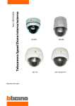
391 696
Manuale di istruzioni
User manual
391 696 - SPEED DOME D/N INTERNI
INDOOR SPEED DOME CAMERA
ZOOM 27x
Part. LE03110AA
391696
2
IT
CARATTERISTICHE
•
Telecamera con potente zoom e opzioni di configurazione
Zoom ottico 27x, zoom digitale 12x (ingrandimento zoom max 324x)
Elevata compensazione del controluce
Funzione Privacy Mask (Zona Privata)
Funzione Day & Night
Modalità messa a fuoco: Auto-Focus, Manual Focus, Semi-Auto Focus
Menu OSD
Sensore immagine: ¼” super HAD color CCD
•
Potenti funzioni Pan/Tilt
• Movimenti Pan/Tilt (rotazione/inclinazione) ad elevata velocità, 360°/sec MAX.
• Grazie alla tecnologia Vector Drive, i movimenti Pan/Tilt seguono il percorso più corto. Il risultato è che il tempo
per seguire il bersaglio si riduce di molto e il video sul monitor appare molto naturale durante il monitoraggio.
• Grazie alla tecnologia di controllo Micro-Stepping, il video appare molto naturale al più elevato ingrandimento di
zoom durante l’azionamento del jog su un controller, perché la telecamera può essere controllata per 0,05°/sec.
Per cui è molto facile mettere a fuoco la telecamera sul bersaglio desiderato anche con il più elevato ingrandimento di zoom. Inoltre, è anche semplice mettere a fuoco la telecamera su delle posizioni scelte grazie al movimento
pan/tilt proporzionale allo zoom.
•
Preset, Pattern, Swing, Gruppi, Privacy Mask e molto di più…
• Sono programmabili MAX 127 Preset (preposizionamenti) e ciascuno di essi può avere i suoi propri valori di configurazione, indipendentemente dagli altri preset.
• Per un esempio, vedi la tabella qui sotto.
N° Preset.
Bilanciamento
del bianco
Esposizione
automatica
Preset 1
Casella A
Casella 3
“INGRESSO”
Preset 2
Casella C
Casella 5
“MAGAZZINO”
Preset 3
Casella V
Casella 2
“UFFICIO”
-
-
Casella K
Casella 9
•••
Etichetta
Osservazioni
•••
Preset 95
-
-
Dedicato menu
OSD
•••
Preset 128
•
•
•
•
•
“TERRAZZO”
Sono programmabili MAX 8 set di Swing. Questa funzione permette alla telecamera di muoversi in modo ripetitivo tra due posizioni predefinite alle velocità programmate.
Sono programmabili MAX 4 Pattern. Questa funzione permette alla telecamera di memorizzare il percorso (in
particolare un percorso curvo) effettuato con il joystick del controller e ripete la traiettoria eseguita con il joystick
con la maggiore precisione possibile.
Sono programmabili MAX 8 set di Gruppi. Questa funzione permette alla telecamera di memorizzare una combinazione di Preset, Pattern e/o Swing in sequenza e mette in funzione Preset, Pattern e/o Swing in modo ripetitivo. Un gruppo può essere combinato con fino a 20 funzioni con qualsiasi Preset/Pattern/Swing.
Sono programmabili 8 Privacy Mask, utilizzate per non violare la privacy altrui.
3
• Controllo PTZ (Pan/Tilt/Zoom) (Rotazione/Inclinazione/Zoom)
• Con la connessione di comunicazione RS-485, possono essere collegate ad un unico controller 255 unità di
telecamere MAX.
• Nell’attuale versione del firmware, i protocolli Pelco-D o Pelco-P possono essere selezionati come protocollo di
controllo.
• Menu OSD (On Screen Display)
• Il menu OSD serve per visualizzare lo stato della telecamera e per impostare le funzioni in modo interattivo.
• Sul display sono visualizzate informazioni quali ID Telecamera, Angolo Pan/Tilt, Direzione, Ingressi Allarme e Preset.
• Funzione Alarm In/Out
• 4 ingressi per sensori allarme e 2 relè di uscita allarme.
• L’ingresso sensore allarme è disaccoppiato con fotoaccoppiatori per evitare completamente rumori e scariche elettriche esterni.
• Possono essere usati sia sensori N.O. (Normalmente Aperti) che sensori N.C. (Normalmente Chiusi) e il campo del
segnale d’ingresso sensore va da 5,0V a 12,0V DC per varie applicazioni.
• La telecamera può essere regolata per muoversi verso una posizione predefinita (Preset) o per attivare funzioni quali Pattern, Swing e Gruppi quando ci sono attivazioni da sensori esterni. È anche disponibile una funzione“Post Alarm”, che si
attiva dopo un tempo predefinito dall’utente, in sequenza e consecutivamente all’azione di attivazioni di sensori esterni.
• Preset dedicati (tasti di scelta rapida)
• La maggior parte delle opzioni di configurazione della telecamera possono essere regolate facilmente e direttamente con dei preset dedicati (tasti scelta rapida) senza accedere al menu OSD. Per ulteriori informazioni, vedi
“Preset dedicati (tasti di scelta rapida)”.
Attenzione
- L’installazione e la taratura di questa telecamera devono essere eseguite da personale qualificato.
- Non aprire la telecamera, esiste il rischio di scosse elettriche.
- Le telecamere a bassa tensione devono essere alimentate da un alimentatore con tensione stabilizzata.
Questa gamma di telecamere è stata realizzata per applicazioni TVCC e non per altri utilizzi.
Utilizzare queste telecamere solo in condizioni di temperatura da (-10) – (+50) °C.
Non utilizzare le telecamere con tensioni differenti da quelle specificate.
L’utilizzo di questo prodotto deve essere fatto nel rispetto delle norme vigenti, sia in materia di privacy (d.lgs.n.196/2003) sia di
tutela dei lavoratori (l.300/1970 Statuto dei lavoratori).
Istruzioni di sicurezza
Questo prodotto deve essere installato in conformità con le regole d’installazione e di preferenza da un elettricista qualificato. L’eventuale installazione e utilizzo improprio dello stesso possono
comportare rischi di shock elettrico o incendio.
Prima di procedere all’installazione, leggere attentamente le istruzioni associate e individuare un luogo di montaggio idoneo in funzione del prodotto.
Non aprire, smontare, alterare o modificare l’apparecchio eccetto speciale menzione indicata nel manuale. Tutti i prodotti Bticino devono essere esclusivamente aperti e riparati da personale adeguatamente formato e autorizzato da Bticino. Qualsivoglia apertura o riparazione non autorizzata comporta l’esclusione di eventuali responsabilità, diritti alla sostituzione e garanzie.
Utilizzare esclusivamente accessori a marchio Bticino.
391696
4
CONTENUTO DELLA CONFEZIONE
• Prodotto e accessori
Corpo principale/ Copriterminali
Copertura cupola
Viti
• Optional
Staffa di montaggio in
controsoffitto
Cod. 391885
Staffa di montaggio a soffitto
Cod. 391883
Staffa angolare
Cod. 391849
Staffa di montaggio a parete
Cod. 391847
5
Descrizione della parte principale
•
Copertura cupola
Non staccare la protezione di vinile dalla copertura della cupola prima di aver completato le operazioni di installazione, in modo da proteggere la copertura da graffi o polvere.
•
Copriterminali
È usato per installare la telecamera direttamente sul soffitto o per attaccarla ad altre staffe come quella per montaggio in controsoffitto, a soffitto e a parete. Prima separare questa copertura e poi attaccare direttamente al soffitto o
ad un’altra staffa. La telecamera va montata per ultima..
•
Molla e gancio anticaduta
Queste parti evitano che la telecamera possa cadere durante le operazioni di installazione e manutenzione. Dopo
aver installato il copriterminali, agganciare la molla al gancio anticaduta del corpo principale come mostrato nella
figura, per effettuare ulteriori operazioni.
•
Vite di blocco
Dopo aver montato il copriterminali al corpo principale, avvitare il copriterminali al corpo principale per evitare che
vengano separati a causa di vibrazioni o altro.
•
Fusibile
Il fusibile protegge la telecamera dai danni causati dalla sovracorrente; se si brucia, va sostituito con uno nuovo. Le
specifiche tecniche del fusibile sono 250V 2A. Raccomandiamo comunque di consultare il rivenditore per eliminare
la causa della sovracorrente.
•
Morsettiera di cablaggio
Durante l’installazione, i cavi di alimentazione, video, comunicazione, I/O allarmi, vanno collegati a questa morsettiera di cablaggio.
391696
6
MONTAGGIO DEL COPRITERMINALI
a Togliere la vite di blocco come mostrato
nella figura qui sotto.
b Girare il corpo principale sul suo asse in senso antiorario e staccarlo dal copriterminali.
MONTAGGIO DEL COPRITERMINALI
c Controllare che la parte superiore della molla piatta si trovi sul segno della freccia come
mostrato all’interno del cerchio tratteggiato
qui sotto.
d Controllare le 2 linee incise per assemblaggio
prima di iniziare il montaggio.
Allineare le linee come mostrato nel cerchio
tratteggiato qui sotto e girare il corpo
principale sul suo asse in senso orario, quindi
montare il corpo principale sul copriterminali.
Dopo averli assemblati, avvitare il corpo
principale al copriterminali per evitare che
vengano separati a causa di vibrazioni o altro.
7
CONFIGURAZIONE DIP SWITCH
• Prima di installare la telecamera, si devono regolare i DIP switch per impostare l’ID della telecamera e il protocollo
di comunicazione. Non usare il connettore ISP. (Solo personale autorizzato!)
Connetore ISP
(per upgrade del sistema)
Protocollo di
communicazione
ID Telecamera
INDIRIZZI (ID)
Vedi
manuale
NC (Normalemente chiuso)
NO (Normalemente aperto)
• Configurazione ID telecamera
)*
)*
$
•
•
•
%
&
'
(
+
$
%
&
'
$
&
+
$(
(
+
(&
I numeri ID delle telecamere sono configurati con numeri binari. Vedi gli esempi indicati qui sotto.
Pin
1
2
3
4
5
6
7
8
Valore ID
1
2
4
8
16
32
64
128
ex: ID = 5
ex: ID = 10
on
off
off
on
on
off
off
on
off
off
off
off
off
off
off
off
L’intervallo dell’ID è 1~255. Non usare 0 come ID telecamera. Il valore predefinito di fabbrica dell’ID telecamera è “1”.
Se si vuole controllare una data telecamera, far corrispondere l’ID telecamera con l’impostazione del Cam ID del DVR
o del Controller.
391696
8
• Configurazione del protocollo di comunicazione
• Scegliere un protocollo adatto alla combinazione dei DIP switch.
Stato DIP switch
Protocollo/Velocità di
trasmissione
P0
(Pin 1)
P1
(Pin 2)
P2
(Pin 3)
OFF
OFF
OFF
PELCO-D, 2400 bps
ON
OFF
OFF
PELCO-D, 9600 bps
OFF
ON
OFF
PELCO-P, 4800 bps
ON
ON
OFF
PELCO-P, 9600 bps
Otherwise
Reserved
• Se si vuole controllare usando i controller DVR o Pan/Tilt, i loro protocolli devono essere identici alla telecamera,
altrimenti non sarà possibile controllarla.
• Se si cambia il protocollo della telecamera cambiando il DIP switch, la modifica sarà attiva dopo aver riavviato la
telecamera.
• Il protocollo predefinito di fabbrica è “Pelco-D, 2400 bps”.
• Configurazione tipo di sensore
• Se si vuole usare l’ingresso allarme, devono essere selezionati i tipi di sensore. I tipi di sensore sono Normalmente Aperto
e Normalmente Chiuso.
Normalmente Aperto
La tensione d’uscita è in stato alto se il sensore è attivato.
Normalmente Chiuso
La tensione d’uscita è in stato alto se il sensore non è attivato.
N° pin
ST1 (Pin 4)
ST2 (Pin 5)
ST3 (Pin 6)
ST4 (Pin 7)
Stato switch
Tipo sensore
ON
Sensore 1: tipo Normalmente Chiuso
OFF
Sensore 1: tipo Normalmente Aperto
ON
Sensore 2: tipo Normalmente Chiuso
OFF
Sensore 2: tipo Normalmente Aperto
ON
Sensore 3: tipo Normalmente Chiuso
OFF
Sensore 3: tipo Normalmente Aperto
ON
Sensore 4: tipo Normalmente Chiuso
OFF
Sensore 4: tipo Normalmente Aperto
9
• Configurazione resistenza terminale
• La resistenza terminale è utilizzata se il sistema è in uno dei due casi seguenti.
•
Caso 1: la lunghezza del cavo di comando tra telecamera e controller è relativamente molto lunga
(connessione 1:1)
Se la lunghezza del cavo di comunicazione è molto lunga, il segnale elettrico rimbalzerà nel punto terminale.
Questo segnale riflesso provoca la distorsione del segnale originale e, di conseguenza, la telecamera può andare
fuori controllo. In questo caso, la resistenza terminale di entrambi i lati, cioè telecamera e controller, deve essere
regolata sullo stato ‘ON’.
•
Caso 2: sono controllate più telecamere contemporaneamente
Per motivi simili al caso 1, le resistenze terminali del controller e dell’ultima telecamera devono essere regolate sullo
stato ‘ON’. L’ultima telecamera è decisa dalla lunghezza del cavo. Non mettere su ON la resistenza terminale di tutte
le telecamere.
Le informazioni complete si trovano sul manuale contenuto nel CD-ROM.
391696
10
INSTALLAZIONE DIRETTA A SOFFITTO
a Per far passare i cavi dalla parte superiore del soffitto, fare un foro di circa 50~60mm nel pannello del
soffitto.
bPer la connessione dei cavi, togliere il segno di foro
predefinito sulla guarnizione di gomma e posizionare
la parte superiore della molla piatta sul segno della
freccia, come mostrato nel cerchio tratteggiato qui
sotto.
&
& messo la guarnizione di gomma sul coc Dopo aver
&
priterminali, installare il copriterminali al soffitto e
collegare i cavi alle morsettiere.
'
'
'd Collegare la “molla anticaduta” al corpo principale per
evitare che la telecamera cada.
'
#
e Controllare le 2 linee incise per assemblaggio prima
di iniziare il montaggio. Allineare le linee come mostrato nel cerchio tratteggiato qui sotto e girare il
corpo principale sul suo asse in senso orario, quindi
montare il corpo principale sul copriterminali.
f Serrare la vite di blocco come indicato qui sotto
#
11
INSTALLAZIONE UTILIZZANDO LA STAFFA DI MONTAGGIO IN CONTROSOFFITTO COD. 391885
$
%
a Tagliare il pannello del controsoffitto come
mostrato qui sotto.
$
%
bMontare il copriterminali della telecamera sulla staffa
per montaggio in controsoffitto come mostrato qui
sotto.
Dimensioni foro (mm)
c Posizionare la parte superiore della molla piatta sul
segno della freccia come mostrato nel cerchio tratteggiato qui sotto.
d Montare il corpo principale al copriterminali e inserire
questo assieme nel soffitto.
I fori vanno usati per sostenere il dispositivo.
e Attaccare la telecamera al soffitto avvitando a fondo
le 3 viti.
$
$
$ f Montare il collare decorativo alla telecamera e farlo
$
ruotare
sul suo asse in senso orario.
-
391696
12
INSTALLAZIONE CON STAFFA DI MONTAGGIO A SOFFITTO COD. 391883
a Per far passare i cavi dalla parte superiore del soffitto, tagliare un foro del diametro di circa 50~60mm
nel pannello del soffitto e attaccarci sopra la staffa di
montaggio a soffitto.
bMontare il copriterminali sulla staffa di montaggio a
soffitto con 3 viti.
(Non usare la guarnizione di gomma!)
Posizionare la parte superiore della molla piatta sul
segno della freccia. (Per ulteriori informazioni, vedi il
,
paragrafo “Montaggio
del copriterminali”).
,
,
,
-
c Collegare la “molla anticaduta” al corpo principale
per evitare che la telecamera cada. Allineare le linee
incise- e girare il corpo principale sul suo asse in senso orario, quindi assemblare il corpo principale al
copriterminali.
d Dopo averli assemblati, avvitare il corpo principale
al copriterminali per evitare che vengano separati a
causa di vibrazioni o altro.
13
INSTALLAZIONE USANDO LA STAFFA DI MONTAGGIO A PARETE COD. 391847
a Installare la staffa di montaggio a parete sulla parete.
bMontare il copriterminali sulla staffa di montaggio a
parete con 3 viti.
(Non usare la guarnizione di gomma!)
Posizionare la parte superiore della molla piatta sul
segno della freccia. (Per ulteriori informazioni, vedere
il paragrafo “Montaggio del copriterminali”).
)
)
)
*
*
*
c Collegare
la “molla anticaduta” al corpo principale
per evitare che la telecamera cada. Allineare le linee
incise e girare il corpo principale sul suo asse in senso orario, quindi assemblare il corpo principale al
copriterminali.
*
)
d Dopo averli assemblati, avvitare il corpo principale
al copriterminali per evitare che vengano separati a
causa di vibrazioni o altro.
391696
14
COLLEGAMENTI E CABLAGGIO
Alimentazione
Sensore
IrDA
ALIM(+ )
ALIM(-)
IN COM+
IN1
VIDEO(+ )
IN2
VIDEO(-)
IN3
RS- 485(+ )
IN4
RS-485(-)
RELÈ1
RELÈ2
Interruttore
porta
Sensore
Luce
BNC
Monitor
RS-485
Cicalino
allarme
Controller
/ DVR
Dispositivi uscita
Copriterminali
Copriterminali
• Collegamento dell’alimentazione elettrica
Controllare attentamente la capacità di corrente e tensione della potenza nominale.
La potenza nominale è indicata sul retro dell’unità principale.
Potenza nominale
Intervallo tensione in ingresso
Consumo corrente
DC 12V
DC 11V ~ 15V
0,75 A
• Collegamenti Video
• Usare il cavo coassiale BNC.
• Comunicazione RS-485
Per il controllo PTZ, collegare questa linea alla tastiera e al DVR. Per controllare più telecamere contemporaneamente,
le loro linee di comunicazione RS-485 vanno collegate in parallelo, come mostrato qui sotto.
Controller Tastiera / DVR
15
• Collegamento I/O allarme
• Ingressi sensori
Interno
Uscita sensore 1
Uscita sensore 4
Prima di collegare i sensori, controllare le tensioni di comando e i tipi di segnale di uscita dei sensori. Dato che i tipi di segnale di uscita dei sensori si dividono in generale in Collettore Aperto e Uscita di Tensione, il cablaggio deve essere fatto
in modo corretto dopo aver preso in considerazione queste tipologie. Inoltre, deve essere impostato correttamente il tipo
di sensore, cioè “Normalmente Aperto” o “Normalmente Chiuso” sul Dip switch del corpo principale della telecamera.
Segnale
IN COM +
IN1-, IN2-, IN3-, IN4-
Descrizione
Connettere il cavo (+) dell’alimentazione elettrica per comandare i sensori su
questa porta, come mostrato nel circuito qui sopra.
Connettere le uscite dei sensori a ciascuna porta, come mostrato nel circuito
qui sopra.
• Uscita relè
Interno
CARRICO
CARRICO
Il carico elettrico massimo ammesso sul relè è indicato nella seguente tabella.
Potenza di azionamento
Alimentazione DC
Alimentazione AC
Carico max
28V, 3A DC
110V, 3A
391696
16
CONTROLLI PRIMA DELLA MESSA IN FUNZIONE
• Prima di accendere il sistema, controllare che il/i filo/i e il/i cavo/i siano collegati correttamente.
• Controllare che l’ID telecamera sul controller sia selezionato correttamente. L’ID telecamera deve essere identico a
quello della telecamera bersaglio. L’ID telecamera si può controllare leggendo il DIP switch della telecamera oppure
sull’OSD.
• Se il controller supporta protocolli multipli, il protocollo deve essere modificato per corrispondere a quello della
telecamera.
• Regolare il DIP switch dopo aver spento la telecamera. Se si cambia il protocollo della telecamera cambiando il DIP
switch, la modifica sarà attiva dopo aver riavviato la telecamera.
• Dato che i controller possono avere modalità di funzionamento differenti, fare riferimento al manuale di istruzioni
del controller se non si riesce a controllare correttamente la telecamera. Il funzionamento in questo manuale si basa
sullo standard Pelco® Controller..
17
SPECIFICHE TECNICHE
• Aspetto
TELECAMERA
PAL
CCD
CCD Super HAD color da 1/4''
Pixel max
795(O)x596(V) 470K
Pixel effettivi
752(O)x582(V) 440K
Risoluzione oriz.
550 linee TV (Colore), 680 linee TV (B/N)
Rapporto S/R
50 dB (AGC OFF)
Zoom
Zoom ottico x27, Zoom digitale x12
Lunghezza focale
f=3,5~94,5 mm (Lf 0,6~2,9)
Illuminazione min
0,4 Lux/Lf 1,6 (Colore), 0, 02 Lux/Lf 1,6 (B/N), 50 IRE
Day & Night
Auto / Day / Night(ICR)
Messa a fuoco
Auto / Manuale / SemiAuto
D
Diaframma
Velocità shutter
elettronico)
(otturatore
;" D
D
Basso / Medio
/ Elevato /DManuale / OFF
D
Auto / Manuale (guadagno rosso, blu regolabile)
D
D
Flickerless (rimozione sfarfallio)
BLC / HLC / OFF
Basso / Medio /Alto / OFF
ON / OFF
"
PAN/TILT
Pan 360°(infinito)
/ Tilt 95°
"
Preset: 360°/sec
Manuale: 0,05 ~ 360°/sec (proporzionale allo zoom)
Swing: 1~ 180°sec
Preset
127 preset (etichetta, regolazione
immagine telecamera)
"
Pattern
4 pattern, 1200 comandi (ca 5 min)/Pattern
Swing
8 Swing
Gruppi
8 gruppi (insiemi di 20 azioni per gruppo)
Auto Flip, Auto Parking, Azioni accensione, ecc.
GENERALE
Comunicazione
RS-485
Protocollo
Pelco-D, Pelco-P selezionabile
I/O Allarmi
4 ingressi / 2 uscite 28 V 3 A
Zone Privacy Mask
OSD
Dimensioni
Peso
Temp.funzionamento
;" D
Selezionabile
Stabilizzazione
Altre funzioni
D
D
x256 ~ 1/120000 sec
Compensazione del controluce
(BLC)
Velocità Pan/Tilt
D
;" D
Bilanciamento del bianco
Campo
D
;" D
D
Controllo automatico del guadagno (AGC)
SSNR
D
Auto / Manuale
Unità principale
8 zone
Menu / Informazioni PTZ, ecc.
Cupola: Ø 149
Alloggiamento: Ø 160 x 212(O) mm
ca 2 kg
0°C ~ 40°C
* Le specifiche di questo prodotto possono essere modificate senza preavviso.
391696
18
DIMENSIONI
• Corpo principale e copriterminali
• Staffa di montaggio a controsoffitto cod. 391885
Dimensioni foro (mm)
• Staffa di montaggio a soffitto cod. 391883
• Staffa di montaggio a parete cod. 391847
Unit (mm)
19
UK
FEATURES
•
Powerful Zoom Camera & Setup Options
27x Optical Zoom, 12x Digital Zoom (324x Max. zoom magnification)
High light compensation
Privacy Mask
Day & Night
Focus Mode : Auto-Focus, Manual Focus, Semi-Auto Focus
OSD Menu
Image Sensor : ¼” Sony interline Transfer CCD
•
Powerful Pan/Tilt Functions
• MAX. 360°/sec High Speed Pan/Tilt Motion
• With the Vector Drive Technology, Pan/Tilt motions are accomplished along the shortest path. As a result, the time
to target view is remarkably short and the video on the monitor is very natural in monitoring.
• With the Micro-Stepping Control Technology, the video looks very natural at high zoom magnification during a
jog operation on a controller since the camera can be controlled by 0.05°/sec. Hence it is very easy to make the
camera focus on desired target views at high zoom magnification. Additionally it is easy to make the camera focus
on desired positions with zoom-proportional pan/tilt movement.
•
Preset, Pattern, Swing, Group, Privacy Mask and More…
• MAX. 127 Presets are programmable and each preset can have its own parameter values independently from the
other presets.
• For an example, refer to the below table.
Preset No.
White Balance
Auto Exposure
•••
Label
Preset 1
Case A
Case 3
“ENTRANCE”
Preset 2
Case C
Case 5
“WAREHOUSE”
Preset 3
Case V
Case 2
“OFFICE”
-
-
Case K
Case 9
Remarks
•••
Preset 95
-
-
Reserved for
OSD Menu
•••
Preset 128
“TERRACE”
•
MAX. 8 sets of Swing are programmable. This function is that the camera moves repetitively between two preset
positions at programmed speeds.
•
MAX. 4 Patterns are programmable. This function is that the camera memorizes the path (mostly curve path) by
the joystick of the controller and revives the trajectory operated by the joystick as closely as possible.
•
MAX. 8 sets of Group are programmable. This function is that the camera memorizes the combination of Presets,
Pattern and/or Swings sequently and runs Presets, Pattern and/or Swings repetitively. A Group can be combined
upto 20 functions with any of Preset/Pattern/Swing.
•
4 Privacy Masks are programmable, not to intrude on any other’s privacy.
391696
20
• PTZ (Pan/Tilt/Zoom) Control
• With the RS-485 communication connection, MAX. 255 units of cameras can be connected to a single controller.
• Pelco-D or Pelco-P protocols can be selected as a control protocol in the current firmware version.
• OSD (On Screen Display) Menu
• OSD menu is provided to display the status of camera and to configure the functions interactively.
• The information such as Camera ID, Pan/Tilt Angle, Direction, Alarm Input and Preset is displayed on screen.
• Alarm In/Out Function
• 4 alarm sensor inputs and 2 alarm sensor outputs relays.
• Alarm sensor input is decoupled with photo-couplers to avoid external electric noise and shock perfectly.
• Both of N.O.(Normal Open) sensors and N.C.(Normal Close) sensors can be used and the signal range of the sensor
input is from DC 5.0V to 12.0V for various applications.
• The camera can be set to move to a Preset position or to run functions such as Pattern, Swing and Group
when there are external sensor activations. Also “Post Alarm” function is possible, which is supposed to activate after user-defined time period and sequentially in succession to the action by external sensor activations.
• Reserved Presets (Hot Keys)
• Most camera setup options can be set up easily and directly with the reserved presets (Hot Keys), without entering
into OSD menu. For more information, refer to “Reserved Presets (Hot Keys)”.
Warning
- The installation and calibration of this camera must be carried out by highly skilled personnel.
- Do not open the camera: there may be a risk of electric shock.
- Low voltage cameras must be powered by a power supply unit with stabilized voltage.
This range of cameras has been created for CCTV applications and not for other uses.
Use these cameras only for the following temperature conditions: from (-10) – (+50) °C.
Do not use the cameras with voltages different from the ones specified.
Safety instructions
This product should be installed in line with installation rules, preferably by a qualified electrician. Incorrect installation and use can lead to risk of electric shock or fire.
Before carrying out the installation, read the instructions and take account of the product’s specific mounting location.
Do not open up, dismantle, alter or modify the device except where specifically required to do so by the instructions. All Bticino products must be opened and repaired exclusively by personnel trained
and approved by Bticino. Any unauthorised opening or repair completely cancels all liabilities and the rights to replacement and guarantees.
Use only Bticino brand accessories.
21
PACKAGE COMPONENT
• Product & Accessories
•
Optional
391696
22
MAIN PART DESCRIPTION
•
Dome Cover
Do not detach the protection vinyl from the dome cover before finishing all the installation process to protect the
dome cover from scratches or dust.
•
Terminal Cover
This is used to install the camera directly on the ceiling or attach to the other brackets such as in-ceiling, ceiling and
wall mount. After separating this cover first and then attach this directly to ceiling or to the other bracket. Camera
must be assembled at the last stage.
•
Drop Prevention Spring - Drop Prevention Hook
This part keeps the camera from dropping during installation and maintenance. After install the Terminal Cover,
please, hang the spring to the drop prevention hook of main body as shown in picture for further tasks
•
Lockup Screw
After assembling Terminal Cover to main body, screw Terminal Cover to main body to protect them from separation
by vibration and so on.
•
Fuse
If the fuse is burnt to protect your came from over-current damage, the fuse have to be replace with new one. The
fuse specification is 250V 2A. However, we recommend consulting with supplier to remove the cause of over-current.
•
Cabling Terminal Block
During installation, Power, Video, Communication, Alarm I/O cables are connected on to this cabling terminal block.
23
TERMINAL COVER DISASSEMBLY
a Remove the Lockup Screw as shown bellow
b Turn main body on its axis in CCW(Counterclockwise) direction and separate it from
Terminal Cover.
TERMINAL COVER ASSEMBLY
c Check if the summit of the Plate Spring is
located at the arrow mark as shown in the
dotted circle.
d Check the 2 mold line for assembly before
starting assembly. Line up the mold lines
as shown in the dotted circle and turn main
body on its axis in CW(Clockwise) direction
and assemble main body to Terminal Cover.
After assembling them, screw main body to
Terminal Cover to protect them from separation by vibration and so on.
391696
24
DIP SWITCH SETUP
• Before you install the camera, you should set the DIP switches to configure the camera ID, communication protocol.
Do not use the ISP connector. (Authorized person only !)
• Camera ID Setup
)*
)*
$
•
•
•
%
&
'
(
+
$
%
&
'
$
&
+
$(
(
+
(&
DID numbers of cameras are set up with binary numbers. See the examples shown below.
Pin
1
2
3
4
5
6
7
8
Binary Value
1
2
4
8
16
32
64
128
ex: ID = 5
ex: ID = 10
on
off
off
on
on
off
off
on
off
off
off
off
off
off
off
off
The range of ID is 1~255. Do not use 0 as camera ID. Factory default of Camera ID is 1.
If you want to control a certain camera, you must match the camera ID with Cam ID setting of DVR or Controller.
25
• Communication Protocol Setup
• Select an appropriate Protocol with the DIP switch combination.
Switch State
P0
(Pin 1)
P1
(Pin 2)
P2
(Pin 3)
Protocol
OFF
OFF
OFF
PELCO-D, 2400 bps
ON
OFF
OFF
PELCO-D, 9600 bps
OFF
ON
OFF
PELCO-P, 4800 bps
ON
ON
OFF
PELCO-P, 9600 bps
Otherwise
Reserved
• If you want to control using DVR or P/T controller, their protocol must be identical to camera. Otherwise, you can not
control the camera.
• If you changed camera protocol by changing DIP S/W, the change will be effective after you reboot the camera.
• Factory default of protocol is “Pelco-D, 2400 bps”.
• If you want to use Alarm Input, the types of sensor must be selected. The sensor types are Normal Open and Normal.
• Sensor type sensor
• If you want to use Alarm Input, the types of sensor must be selected. The sensor types are Normal Open and Normal.
Normal Open
Output Voltage is high state when sensor is activated.
Normal Close
Output Voltage is high state when sensor is not activated.
Pin No
Switch State
Sensor type
ST1 (Pin 4)
ON
Sensor 1 : Normal Close Type
OFF
Sensor 1 : Normal Open Type
ON
Sensor 2 : Normal Close Type
OFF
Sensor 2 : Normal Open Type
ON
Sensor 3 : Normal Close Type
OFF
Sensor 3 : Normal Open Type
ST2 (Pin 5)
ST3 (Pin 6)
ST4 (Pin 7)
ON
Sensor 4 : Normal Close Type
OFF
Sensor 4 : Normal Open Type
391696
26
• Terminal Resistor Setup
• The terminal resistor is used if your system is one of following two cases.
•
Case 1: Control cable between camera and controller is relatively very long (1:1 connection)
If communication cable is very long, the electrical signal will bound in the terminal point. This reflected signal
cause distortion of original signal. Accordingly, the camera can be out of control. In this case, the terminal
resistor of both sides i.e. camera and controller must be set to ‘ON’ state.
•
Case 2: Multiple cameras are controlled at the same time
Due to similar reasons with case 1, the terminal resisters of controller and the last camera must be set to ‘ON’
state. Last camera means decided by cable length. Do not turn on the terminal resistor of all cameras.
The complete informations are in the manual on the CDrom
27
DIRECT INSTALLATION ON THE CEILING
a To pass cables to upside of ceiling, please, make
about 50~60mm hole on the ceiling panel.
bFor cable connection, remove the pre-defined hole
mark on the Rubber Gasket and locate the summit of
the Plate Spring at the arrow mark as shown in the
dotted circle.
&
&
c After assembling
the Rubber Gasket to the Terminal
&
Cover, install Terminal Cover on ceiling tex and connect cables to terminal blocks.
'
#
e Check the 2 mold line for assembly before starting
assembly. Line up the mold lines as shown in the dotted circle and turn main body on its axis in CW(ClockWise) direction and assemble main body to Terminal
Cove
'
'
'd Connect the “Drop Prevention Spring” to the main
body to prevent camera from drop.
#
f Tighten the Lockup Screw as shown bellow.
391696
28
INSTALLATION USING REF. 391885 IN-CEILING MOUNT BRACKET
$
a Cut the panel of ceiling as shown bellow.
%
$
%
c Locate the summit of the plate spring at the arrow
mark as shown in the dotted cir
d Assemble main body to Terminal Cover and insert the
assembly into ceiling tex.
Holes are to be used to sustain the device.
e Screw camera to ceiling tex with 3 screws tightly.
$
$
bAssemble Terminal Cover of camera to the In-Ceiling
Mount Bracket as shown bellow.
$ f Assemble Deco. Ring with camera and turn Deco.
$ on its axis in CW(Clockwise) direction.
Ring
-
29
INSTALLATION USING REF. 391883 CEILING MOUNT BRACKET
a To pass cables to upside of ceiling, please make
about 50~60mm hole on the ceiling panel and attach the Ceiling mount bracket on it.
bAssemble Terminal Cover to Ceiling Mount Bracket
with 3 screws. (Do not use Rubber Gasket !)
Locate the summit of the Plate Spring at the arrow
mark. (For more information, refer to the “Terminal
Cover Assembling” section)
,
,
,
,
-
c Connect “Drop Prevention Spring” to main body to
prevent camera from drop. Line up the mold lines
and -turn main body on its axis in CW(Clockwise)
direction and assemble main body to Terminal
Cover.
d After assembling them, screw main body to Terminal
Cover to protect them from separation by vibration
and so on.
391696
30
INSTALLATION USING REF. 391847 WALL MOUNT BRACKET
a Install Wall Mount Bracket on wall.
bAssemble Terminal Cover to Wall Mount Bracket with
3 screws. (Do not use Rubber Gasket !)
Locate the summit of the Plate Spring at the arrow
mark. (For more information, refer to the “Terminal
Cover Assembling” section)
)
)
*
*
*
c Connect
“Drop Prevention Spring” to main body to
prevent camera from drop. Line up the mold lines
and turn main body on its axis in CW (Clockwise)
direction and assemble main body to Terminal
Cover.
*
)
)
d After assembling them, screw main body to Terminal
Cover to protect them from separation by vibration
and so on.
31
WIRING AND CABLING
&)!*+,
&)!*",
(%/
(%#
Terminal Cover
• Port Connexion
• Please, check the voltage and current capacity of rated power carefully. Rated power is indicated in the back of main
unit.
Rated Power
Input Voltage Range
Current Consumption
DC 12V
DC 11V ~ 15V
0,75 A
• Video connection
• Connect with BNC coaxial cable
• RS-485 Communication
• For PTZ control, connect this line to keyboard and DVR. To control multiple cameras at the same time,
RS-485 communication lines of them is connected in parallel as shown below.
391696
32
• Alarm I/O Connection
• Sensor Input
Before connecting sensors, check driving voltage and output signal type of the sensor. Since output signal types of the
sensors are divided into Open Collector and Voltage Output type in general, the cabling must be done properly after
considering these typed. Also, the sensor type, i.e. “Normal Open” or “Normal Close” in Dip switch in main body of camera
must be set properly.
Signal
Description
IN COM +
Connect (+) cable of electric power source for Sensors to this port as shown in
the circuit above.
IN1-, IN2-, IN3-, IN4-
Connect output of sensors for each port as shown in the circuit above.
• Relay Output
Maximum allowable electrical load of relay is shown bellow table.
Drive Power
DC Power
AC Power
Max. Load
DC 28V, 3A
110V, 3A
33
CHECK POINTS BEFORE OPERATION
• Before turning on the system, check if the wire(s) and cable(s) are connected properly.
• Check if the camera ID on the controller is properly selected. The camera ID must be identical to that of the target
camera. The camera ID can be checked by reading the DIP switch of the camera or on OSD.
• If your controller supports multi-protocols, the protocol must be changed to match to that of the camera.
• Adjust the DIP switch after turning off the camera. If you changed the camera protocol by changing the DIP S/W, the
change will be effective after you reboot the camera.
• Since the operation method can be different by controllers, refer to your controller manual if the camera can not be
controlled properly. The operation of this manual is based on the standard Pelco® Controller.
391696
34
SPECIFICATIONS
• Appearance
CAMERA PART
Video Signal System
CCD
PAL
1/4'' Super HAD color CCD
Max. Pixels
795(H)x96(V) 470K
Effective Pixels
752(H)x582(V) 440K
Horizontal Res.
550 TV Line(Color), 680 TV Line(B/W)
S/N Ratio
Zoom
Focal length
Min. illumination
Day & Night
Focus
Iris
Shutter Speed
AGC
White Balance
BLC
50 dB (AGC Off )
x27 Optical Zoom, x12 Digital Zoom
f=3.5~94.5 mm (F1.6~2.9)
Auto / Day / Night(ICR)
Auto / Manual / SemiAuto
D
Auto / Manual
;" D
D
D
D
D
x256 ~ 1/120000
sec
D
Auto / Manual(Red, Blue Gain Adjustable)
; "BLC
D
D
/ HLC / Off
D
D
Selectable
D
Low / Middle / High / Off
Stabilization
;" D
On / Off
PAN/TILT
Video Signal System
Pan 360°(Endless) / Tilt 95°
Preset : 360°/sec
Pan/Tilt Speed
Manual : 0.05 ~ 360°/sec
(proportional to zoom)
"
Swing : 1~ 180°/sec
Preset
127 Preset (Label, Camera Image Setting)
Pattern
4 Pattern, 1200 commands(about 5 minute)/Pattern
Swing
8"Swing
Group
8 Group (20 action entities per Group)
Other Functions
Auto Flip, Auto Parking, Power Up Action etc.
GENERAL
Communication
RS-485
Protocol
Pelco-D, Pelco-P selectable
Alarm I/O
4 Input / 2 Output 28 V 3 A
Privacy Mask Zone
OSD
Dimension
D
;" D
Low / Middle /DHigh / Manual / Off
Flickerless
SSNR
Main Unit
0.4 Lux/F1.6 (Color), 0. 02 Lux/F1.6 (B/W), 50 IRE
8 Zone
Menu / PTZ information etc.
Dome : Ø 149
Housing : Ø 160 x 212(H) mm
Weight
about 2 kg
Operating Temp.
0°C ~ 40°C
* Specifications of this product can be subjected to change without notice.
"
35
DIMENSION
• Main Body & Terminal cover
• Ceiling Mount Bracket ref. 391883
• In-Ceiling Mount Bracket ref. 391885
• Wall Mount Bracket ref. 391847
Unit (mm)