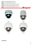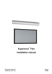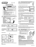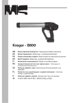
1
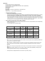
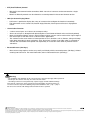
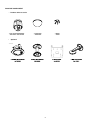
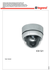
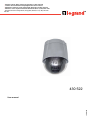
• Caméra couleur dôme motorisée jour/nuit 3,5-94,5 mm 27X
• 3.5-94.5 mm 27X motorized day/night dome colour camera
• Cámara de cúpula en color motorizada día/noche 3,5-94,5 mm 27X
• Câmara a cores cúpula motorizada diurna/nocturna 3,5-94,5 mm 27X
• Kamera kolorowa ze sklepieniem, z napędem, dzień/noc 3,5–94,5 mm 27X
430 522
430 522
LE03666AA
User manual
FEATURES
•
Powerful Zoom Camera & Setup Options
27x Optical Zoom, 12x Digital Zoom (324x Max. zoom magnification)
High light compensation
Privacy Mask
Day & Night
Focus Mode : Auto-Focus, Manual Focus, Semi-Auto Focus
OSD Menu
Image Sensor : ¼” Sony interline Transfer CCD
•
Powerful Pan/Tilt Functions
• MAX. 360°/sec High Speed Pan/Tilt Motion
• With the Vector Drive Technology, Pan/Tilt motions are accomplished along the shortest path. As a result,
the time to target view is remarkably short and the video on the monitor is very natural in monitoring.
• With the Micro-Stepping Control Technology, the video looks very natural at high zoom magnification during a jog operation on a controller since the camera can be controlled by 0.05°/sec. Hence it is very easy to
make the camera focus on desired target views at high zoom magnification. Additionally it is easy to make
the camera focus on desired positions with zoom-proportional pan/tilt movement.
•
Preset, Pattern, Swing, Group, Privacy Mask and More…
• MAX. 127 Presets are programmable and each preset can have its own parameter values independently
from the other presets.
• For an example, refer to the below table.
Preset No.
White Balance
Auto Exposure
Preset 1
Case A
Case 3
“ENTRANCE”
Preset 2
Case C
Case 5
“WAREHOUSE”
Preset 3
Case V
Case 2
“OFFICE”
-
-
Case K
Case 9
•••
Label
Remarks
•••
Preset 95
-
-
Reserved for
OSD Menu
•••
Preset 128
“TERRACE”
•
MAX. 8 sets of Swing are programmable. This function is that the camera moves repetitively between two
preset positions at programmed speeds.
•
MAX. 4 Patterns are programmable. This function is that the camera memorizes the path (mostly curve
path) by the joystick of the controller and revives the trajectory operated by the joystick as closely as
possible.
•
MAX. 8 sets of Group are programmable. This function is that the camera memorizes the combination of
Presets,
Pattern and/or Swings sequently and runs Presets, Pattern and/or Swings repetitively. A Group can be
combined upto 20 functions with any of Preset/Pattern/Swing.
•
4 Privacy Masks are programmable, not to intrude on any other’s privacy.
2
• PTZ (Pan/Tilt/Zoom) Control
• With the RS-485 communication connection, MAX. 255 units of cameras can be connected to a single
controller.
• Pelco-D or Pelco-P protocols can be selected as a control protocol in the current firmware version.
• OSD (On Screen Display) Menu
•
•
OSD menu is provided to display the status of camera and to configure the functions interactively.
The information such as Camera ID, Pan/Tilt Angle, Direction, Alarm Input and Preset is displayed on
screen.
• Alarm In/Out Function
•
•
•
•
4 alarm sensor inputs and 2 alarm sensor outputs relays.
Alarm sensor input is decoupled with photo-couplers to avoid external electric noise and shock perfectly.
Both of N.O.(Normal Open) sensors and N.C.(Normal Close) sensors can be used and the signal range of
the sensor input is from DC 5.0V to 12.0V for various applications.
The camera can be set to move to a Preset position or to run functions such as Pattern, Swing and Group
when there are external sensor activations. Also “Post Alarm” function is possible, which is supposed to
activate after user-defined time period and sequentially in succession to the action by external sensor
activations.
• Reserved Presets (Hot Keys)
•
Most camera setup options can be set up easily and directly with the reserved presets (Hot Keys), without
entering into OSD menu. For more information, refer to “Reserved Presets (Hot Keys)”.
Warning
- The installation and calibration of this camera must be carried out by highly skilled personnel.
- Do not open the camera: there may be a risk of electric shock.
- Low voltage cameras must be powered by a power supply unit with stabilized voltage.
This range of cameras has been created for CCTV applications and not for other uses.
Use these cameras only for the following temperature conditions: from (-10) – (+50) °C.
Do not use the cameras with voltages different from the ones specified.
Safety instructions
This product should be installed in line with installation rules, preferably by a qualified electrician. Incorrect installation and use can lead to risk of electric shock or fire.
Before carrying out the installation, read the instructions and take account of the product’s specific mounting location.
Do not open up, dismantle, alter or modify the device except where specifically required to do so by the instructions. All Legrand products must be opened and repaired exclusively by personnel trained
and approved by Legrand. Any unauthorised opening or repair completely cancels all liabilities and the rights to replacement and guarantees.
Use only Legrand brand accessories.
3
PACKAGE COMPONENT
• Product & Accessories
•
Optional
4
MAIN PART DESCRIPTION
•
Dome Cover
Do not detach the protection vinyl from the dome cover before finishing all the installation process to protect
the dome cover from scratches or dust.
•
Terminal Cover
This is used to install the camera directly on the ceiling or attach to the other brackets such as in-ceiling,
ceiling and wall mount. After separating this cover first and then attach this directly to ceiling or to the other
bracket. Camera must be assembled at the last stage.
•
Drop Prevention Spring - Drop Prevention Hook
This part keeps the camera from dropping during installation and maintenance.
After install the Terminal Cover, please, hang the spring to the drop prevention hook of main body as shown
in picture for further tasks
•
Lockup Screw
After assembling Terminal Cover to main body, screw Terminal Cover to main body to protect them from
separation by vibration and so on.
•
Fuse
If the fuse is burnt to protect your came from over-current damage, the fuse have to be replace with new one.
The fuse specification is 250V 2A. However, we recommend consulting with supplier to remove the cause of
over-current.
•
Cabling Terminal Block
During installation, Power, Video, Communication, Alarm I/O cables are connected on to this cabling terminal
block.
5
TERMINAL COVER DISASSEMBLY
b Turn main body on its axis in
CCW(Counter-clockwise) direction and
separate it from Terminal Cover.
a Remove the Lockup Screw as shown bellow
TERMINAL COVER ASSEMBLY
c Check if the summit of the Plate Spring
is located at the arrow mark as shown in
the dotted circle.
d Check the 2 mold line for assembly
before starting assembly. Line up the
mold lines as shown in the dotted
circle and turn main body on its axis in
CW(Clockwise) direction and assemble
main body to Terminal Cover. After
assembling them, screw main body to
Terminal Cover to protect them from
separation by vibration and so on.
6
DIP SWITCH SETUP
• Before you install the camera, you should set the DIP switches to configure the camera ID, communication
protocol. Do not use the ISP connector. (Authorized person only !)
• Camera ID Setup
)*
)*
$
•
•
•
%
&
'
(
+
$
%
&
'
$
&
+
$(
(
+
(&
DID numbers of cameras are set up with binary numbers. See the examples shown below.
Pin
1
2
3
4
5
6
7
8
Binary Value
1
2
4
8
16
32
64
128
ex: ID = 5
ex: ID = 10
on
off
off
on
on
off
off
on
off
off
off
off
off
off
off
off
The range of ID is 1~255. Do not use 0 as camera ID. Factory default of Camera ID is 1.
If you want to control a certain camera, you must match the camera ID with Cam ID setting of DVR or
Controller.
7
• Communication Protocol Setup
• Select an appropriate Protocol with the DIP switch combination.
Switch State
P0
(Pin 1)
P1
(Pin 2)
P2
(Pin 3)
Protocol
OFF
OFF
OFF
PELCO-D, 2400 bps
ON
OFF
OFF
PELCO-D, 9600 bps
OFF
ON
OFF
PELCO-P, 4800 bps
ON
ON
OFF
PELCO-P, 9600 bps
Otherwise
Reserved
• If you want to control using DVR or P/T controller, their protocol must be identical to camera. Otherwise, you can
not control the camera.
• If you changed camera protocol by changing DIP S/W, the change will be effective after you reboot the camera.
• Factory default of protocol is “Pelco-D, 2400 bps”.
• If you want to use Alarm Input, the types of sensor must be selected. The sensor types are Normal Open and
Normal.
• Sensor type sensor
• If you want to use Alarm Input, the types of sensor must be selected. The sensor types are Normal Open and
Normal.
m
Normal Open
Output Voltage is high state when sensor is activated.
m
Normal Close
Output Voltage is high state when sensor is not activated.
Pin No
Switch State
Sensor type
ST1 (Pin 4)
ON
Sensor 1 : Normal Close Type
OFF
Sensor 1 : Normal Open Type
ON
Sensor 2 : Normal Close Type
OFF
Sensor 2 : Normal Open Type
ON
Sensor 3 : Normal Close Type
OFF
Sensor 3 : Normal Open Type
ON
Sensor 4 : Normal Close Type
OFF
Sensor 4 : Normal Open Type
ST2 (Pin 5)
ST3 (Pin 6)
ST4 (Pin 7)
8
• Terminal Resistor Setup
• The terminal resistor is used if your system is one of following two cases.
•
Case 1: Control cable between camera and controller is relatively very long (1:1 connection)
If communication cable is very long, the electrical signal will bound in the terminal point.
This reflected signal cause distortion of original signal. Accordingly, the camera can be out of control.
In this case, the terminal resistor of both sides i.e. camera and controller must be set to ‘ON’ state.
•
Case 2: Multiple cameras are controlled at the same time
Due to similar reasons with case 1, the terminal resisters of controller and the last camera must be set
to ‘ON’ state. Last camera means decided by cable length. Do not turn on the terminal resistor of all
cameras.
The complete informations are in the manual on the CDrom
9
DIRECT INSTALLATION ON THE CEILING
a To pass cables to upside of ceiling, please, make
about 50~60mm hole on the ceiling panel.
bFor cable connection, remove the pre-defined hole
mark on the Rubber Gasket and locate the summit
of the Plate Spring at the arrow mark as shown in
the dotted circle.
&
&
c After assembling
the Rubber Gasket to the
&
Terminal Cover, install Terminal Cover on ceiling
tex and connect cables to terminal blocks.
'
'
'
'd Connect the “Drop Prevention Spring” to the main
body to prevent camera from drop.
#
#
f Tighten the Lockup Screw as shown bellow.
e Check the 2 mold line for assembly before starting
assembly. Line up the mold lines as shown in
the dotted circle and turn main body on its axis
in CW(Clock-Wise) direction and assemble main
body to Terminal Cove
10
INSTALLATION USING REF. 391885 IN-CEILING MOUNT BRACKET
$
a Cut the panel of ceiling as shown bellow.
%
$
%
bAssemble Terminal Cover of camera to the InCeiling Mount Bracket as shown bellow.
c Locate the summit of the plate spring at the arrow
mark as shown in the dotted cir
d Assemble main body to Terminal Cover and insert
the assembly into ceiling tex.
Holes are to be used to sustain the device.
e Screw camera to ceiling tex with 3 screws tightly.
$ f Assemble Deco. Ring with camera and turn Deco.
$
Ring
on its axis in CW(Clockwise) direction.
$
$
11
-
INSTALLATION USING REF. 391883 CEILING MOUNT BRACKET
a To pass cables to upside of ceiling, please make
about 50~60mm hole on the ceiling panel and
attach the Ceiling mount bracket on it.
bAssemble Terminal Cover to Ceiling Mount Bracket
with 3 screws. (Do not use Rubber Gasket !)
Locate the summit of the Plate Spring at the arrow
mark. (For more information, refer to the “Terminal
Cover Assembling” section)
,
,
,
,
-
c Connect “Drop Prevention Spring” to main body to
prevent camera from drop. Line up the mold lines
and -turn main body on its axis in CW(Clockwise)
direction and assemble main body to Terminal
Cover.
d After assembling them, screw main body to
Terminal Cover to protect them from separation by
vibration and so on.
12
INSTALLATION USING REF. 391847 WALL MOUNT BRACKET
bAssemble Terminal Cover to Wall Mount Bracket
with 3 screws. (Do not use Rubber Gasket !)
Locate the summit of the Plate Spring at the arrow
mark. (For more information, refer to the “Terminal
Cover Assembling” section)
a Install Wall Mount Bracket on wall.
)
)
*
*
*
c Connect
“Drop Prevention Spring” to main body to
prevent camera from drop. Line up the mold lines
and turn main body on its axis in CW (Clockwise)
direction and assemble main body to Terminal
Cover.
)
)
d After assembling them, screw main body to
Terminal Cover to protect them from separation by
vibration and so on.
*
13
WIRING AND CABLING
&)!*+,
&)!*",
(%/
(%#
Terminal Cover
• Port Connexion
• Please, check the voltage and current capacity of rated power carefully. Rated power is indicated in the back of
main unit.
Rated Power
Input Voltage Range
Current Consumption
DC 12V
DC 11V ~ 15V
0,75 A
• Video connection
• Connect with BNC coaxial cable
• RS-485 Communication
• For PTZ control, connect this line to keyboard and DVR. To control multiple cameras at the same time,
RS-485 communication lines of them is connected in parallel as shown below.
14
• Alarm I/O Connection
• Sensor Input
Before connecting sensors, check driving voltage and output signal type of the sensor. Since output signal types
of the sensors are divided into Open Collector and Voltage Output type in general, the cabling must be done
properly after considering these typed. Also, the sensor type, i.e. “Normal Open” or “Normal Close” in Dip switch
in main body of camera must be set properly.
Signal
Description
IN COM +
Connect (+) cable of electric power source for Sensors to this port as
shown in the circuit above.
IN1-, IN2-, IN3-, IN4-
Connect output of sensors for each port as shown in the circuit above.
• Relay Output
Maximum allowable electrical load of relay is shown bellow table.
Drive Power
DC Power
AC Power
Max. Load
DC 28V, 3A
110V, 3A
15
CHECK POINTS BEFORE OPERATION
• Before turning on the system, check if the wire(s) and cable(s) are connected properly.
• Check if the camera ID on the controller is properly selected. The camera ID must be identical to that of the
target camera. The camera ID can be checked by reading the DIP switch of the camera or on OSD.
• If your controller supports multi-protocols, the protocol must be changed to match to that of the camera.
• Adjust the DIP switch after turning off the camera. If you changed the camera protocol by changing the DIP
S/W, the change will be effective after you reboot the camera.
• Since the operation method can be different by controllers, refer to your controller manual if the camera can
not be controlled properly. The operation of this manual is based on the standard Pelco® Controller.
16
SPECIFICATIONS
• Appearance
CAMERA PART
Video Signal System
CCD
PAL
1/4'' Super HAD color CCD
Max. Pixels
795(H)x96(V) 470K
Effective Pixels
752(H)x582(V) 440K
Horizontal Res.
550 TV Line(Color), 680 TV Line(B/W)
S/N Ratio
Zoom
Focal length
Min. illumination
Day & Night
Focus
50 dB (AGC Off)
x27 Optical Zoom, x12 Digital Zoom
f=3.5~94.5 mm (F1.6~2.9)
Auto / Day / Night(ICR)
AGC
White Balance
BLC
D
/ Manual / SemiAuto
D
D
Auto
/ Manual
D
D
D
Low / Middle / High / Manual / Off
Auto / Manual(Red,
Blue Gain
Adjustable)
D
D
;" D
BLC / HLC / Off
D
D
Selectable
Low / Middle / High / Off
Stabilization
;" D
On / Off
• Appearance Alarm
• Sensor Input
"
"
PAN/TILT
Video Signal System
Pan 360°(Endless) / Tilt 95°
Preset : 360°/sec
Pan/Tilt Speed
Manual : 0.05 ~ 360°/sec (proportional to zoom)
Swing
: 1~ 180°/sec
"
Preset
127 Preset (Label, Camera Image Setting)
Pattern
4 Pattern, 1200 commands(about 5 minute)/Pattern
Swing
8 Swing
Group
8 Group (20 action entities per Group)
Other Functions
Auto Flip, Auto Parking, Power Up Action etc.
GENERAL
Communication
RS-485
Protocol
Pelco-D, Pelco-P selectable
Alarm I/O
4 Input / 2 Output 28 V 3 A
Privacy Mask Zone
OSD
Dimension
D
;" D
x256 ~ 1/120000 sec
Flickerless
SSNR
D
;Auto
" D
Iris
Shutter Speed
Main Unit
0.4 Lux/F1.6 (Color), 0. 02 Lux/F1.6 (B/W), 50 IRE
8 Zone
Menu / PTZ information etc.
Dome : Ø 149
Housing : Ø 160 x 212(H) mm
Weight
about 2 kg
Operating Temp.
0°C ~ 40°C
* Specifications of this product can be subjected to change without notice.
17
DIMENSION
• Main Body & Terminal cover
• Ceiling Mount Bracket ref. 391883
• In-Ceiling Mount Bracket ref. 391885
• Wall Mount Bracket ref. 391847
Unit (mm)
18