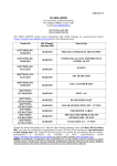
1
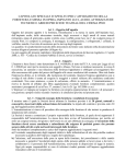
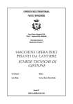
ELEVATORE TELESCOPICO
TELESCOPIC ELEVATOR
ELV 80
ELV 100
ELV 120
MANUALE DI USO E MANUTENZIONE
USER MANUAL
ITALIANO - ENGLISH
MD - MUSICAL ACCESSORIES
di Dino Mazzocchitti
Zona Industriale Piane di S. Andrea
64032 Atri (TE) – ITALY
tel. +39 085 8780125 – fax +39 085 8793077
P.I. 00724830674
www.mdmusicalaccessories.com
Edizione 06/08 - Edition 06/08
Indice / Index
1.Norme ed avvertenze generali / Norms and general instructions
2.Recapiti del costruttore e servizio post-vendita / Manufacture’s address and customer service
3.Dati tecnici / Technical notes
4. Descrizione / Description
5.Trasporto / Transport
6.Sollevamento / Lifting
7.Discesa / Lowering
8.Manutenzione / Maintenance
9.Sicurezza / Safety
ELEVATORE MODELLO /ELEVATOR MODEL ELV 80
ELEVATORE MODELLO /ELEVATOR MODEL ELV 100
ELEVATORE MODELLO /ELEVATOR MODEL ELV 120
3
4
5
8
9
10
14
14
16
18
18
18
Il presente manuale è di proprietà della MD.
MD si riserva il diritto di apportare, in qualsiasi momento e senza preavviso, modifiche per ragioni
tecniche o commerciali.
La riproduzione di qualsiasi parte di questo manuale è vietata ai sensi di legge senza autorizzazione
scritta della MD.
This user manual remains the property of MD
MD reserves the right to modify the specifications at any time and without warning for technical or
commercial reasons.
Reproduction of any part of this manual without written permission from MD is forbidden, according to
law.
1. Norme ed avvertenze generali / Norms and general instructions
Il presente fascicolo, relativamente alla tipologia dell’elevatore telescopico “ELV80 – EVL 100 – ELV 120”
considerato, costituisce uno strumento dettagliatamente preposto all’uso e alla messa in servizio in
condizioni di sicurezza.
Lo scopo del manuale, documentato ed illustrato, è quello di limitare la richiesta di assistenza al
fabbricante garantendo agli operatori, a cui è dedicato, una corretta gestione, evitandone o limitandone i
rischi connessi con l’utilizzo.
This manual is specifically designed for the safe setting up and use of the “ELV80 – ELV100– ELV 120”
telescopic elevator.
The aim of this detailed and illustrated manual is to limit the need for assistance from the manufacturer,
while providing instructions for the correct use of the ELEVATOR, to minimise any potential risks
associated with its use.
ATTENZIONE!
Operatori e tecnici, devono leggere e comprendere
l’intero contenuto del presente manuale.
Il presente manuale e tutta la documentazione allegata,
deve essere conservata per l’intero ciclo di vita
dell’elevatore, in un luogo accessibile a tutto il
personale preposto al sua utilizzo ed alla
manutenzione.
WARNING!
Users and technicians must read and understand the
full content of this manual.
This manual and all of the enclosed documentation
must remain accessible to the personnel in charge of
the use and maintenance of the ELEVATOR for its full
working life.
Il Manuale di istruzioni è da considerarsi parte dell’ ELEVATORE , e deve essere conservato per futuri
riferimenti fino all’eventuale smantellamento definitivo dello stesso.
Sarà cura degli operatori conservarlo in modo idoneo in un apposito vano, noto a tutti gli operatori, protetto
dall’umidità e dai raggi solari.
Si informano gli utenti che il manuale rispecchia lo stato della tecnica al momento della
commercializzazione; eventuali successivi aggiornamenti in base a nuove esperienze non lo renderanno in
alcun modo inadeguato.
This user manual is to be considered part of the ELEVATOR, and must be kept for future reference for its
full working life.
The users are asked to keep these instructions in a proper manner in an assigned location known to all of
the users, away from humidity and light.
The users should be aware that this manual reflects the state of the art at the moment the ELEVATOR was
made available for purchase; any later updates on the basis of new experience will not render it unsuited in
any way.
3/18
2. Recapiti del costruttore e servizio post-vendita / Manufacture’s address and customer service
Il costruttore è disponibile per fornire tutte le informazioni relative all’uso e alla manutenzione dell’
ELEVATORE oggetto di questo manuale.
The manufacturer is available to provide all information related to the use and maintenance of the
ELEVATOR described in this manual.
Qualsiasi richiesta di intervento o informazione deve essere indirizzata al Servizio Tecnico di Assistenza:
Any repair or information request should be addressed to the Technical Support Services:
MD - MUSICAL ACCESSORIES
di Mazzocchitti Dino
Zona Industriale Piane di S. Andrea
64032 Atri (TE) – ITALY
tel. +39 085 8780125
fax +39 085 8793077
P.I. 007248300674
www.mdmusicalaccessories.com
ATTENZIONE: Prima di contattare la MD annotarsi i dati dell’ELEVATORE riportati nella targhetta
di identificazione.
WARNING: Before contacting MD, please note all of the data related to the ELEVATOR that is
shown on the identification label.
ATTENZIONE PERICOLO!
Si fa presente che alcuni ricambi rivestono caratteristiche di sicurezza delle
persone; si fa quindi divieto di utilizzare ricambi diversi da quelli originali. Il cliente
dovrà obbligatoriamente acquistare ricambi originali i quali possono garantire il
funzionamento dell'ELEVATORE in sicurezza.
WARNING DANGER!
Some replacement parts include security features for the user; original
replacement parts must always be used. The customer must purchase original
replacement parts in order to guarantee the safe use of the ELEVATOR.
4/18
3. Dati tecnici / Technical notes
Modello / Model ELV 80
•
•
•
•
•
•
•
•
•
•
•
•
•
•
•
•
•
•
•
•
•
•
•
•
•
•
•
•
Elevatore destinato al sollevamento di carichi verticali a differenti altezze
Carico massimo sollevabile 150 kg
Carico minimo sollevabile 40 kg
Peso 55 kg
Sollevamento del carico su sistema telescopico guidato a 2 sfilate
Cavo di sollevamento in acciaio a due strati di trefoli antigirevole UNI 7302-74
– Ø5 mm – carico di rottura minimo 1800 kg
Argano di sollevamento portata max 240 Kg con dispositivo di bloccaggio del
carico a norme CE
Struttura interamente in acciaio S235 JR
Pulegge e perni in acciaio ad alta resistenza
Superfici protette da corrosione da zincatura elettrolitica e/o verniciatura a
polveri epossidiche
Sistema di bloccaggio di ogni sfilata tipo AUTO-LOCK
Dispositivo per livellamento a terra sui 4 lati dell’elevatore
Ingombri come da figure riportate di seguito
Piedini di appoggio a base circolare Ø90 mm basculanti
Elevator for vertical load lifting to different heights
Maximum load 150 k 330 lbs
Minimum load 40 k 90 lbs
Weight 55 kg /120 lbs
Load lifting on telescopic system supplied by two profiles
Two-strand, twist-resistant steel lifting cable UNI 7302-74 – Ø5 mm –
minimum failure load, 1800 kg/3960 lbs
Lifting winch maximum capacity 240 kg/530 lbs, with load-braking device,
satisfying CE regulations
Whole structure made of S235 JR steel
Pulleys and pins made of high resistance steel
Surfaces protected from corrosion by galvanisation and/or epoxy powder
varnish
AUTO-LOCK blocking system for each profile
Ground levelling device on four sides of the elevator
Overall dimensions as given in the figures below
Adjustable stabilising feet with circular base of Ø90 mm
5/18
Modello / Model ELV 100
•
•
•
•
•
•
•
•
•
•
•
•
•
•
•
•
•
•
•
•
•
•
•
•
•
•
•
•
Elevatore destinato al sollevamento di carichi verticali a differenti altezze
Carico massimo sollevabile 200 kg
Carico minimo sollevabile 50 kg
Peso 70 kg
Sollevamento del carico su sistema telescopico guidato a 3 sfilate
Cavo di sollevamento in acciaio a due strati di trefoli antigirevole UNI 7302-74
– Ø5 mm – carico di rottura minimo 1800 kg
Argano di sollevamento portata max 600 Kg con dispositivo di bloccaggio del
carico a norme CE
Struttura interamente in acciaio S235 JR
Pulegge e perni in acciaio ad alta resistenza
Superfici protette da corrosione da zincatura elettrolitica e/o verniciatura a
polveri epossidiche
Sistema di bloccaggio di ogni sfilata tipo AUTO-LOCK
Dispositivo per livellamento a terra sui 4 lati dell’elevatore
Ingombri come da figure riportate di seguito
Piedini di appoggio a base circolare Ø90 mm basculanti
Elevator for vertical load lifting to different heights
Maximum load 200 kg/440 lbs
Minimum load 50 kg/110 lbs
Weight 70 kg/154 lbs
Load lifting on telescopic system supplied by three profiles
Two-strand, twist-resistant steel lifting cable UNI 7302-74 –- Ø5 mm –
minimum failure load, 1800 kg/3960 lbs
Lifting winch maximum capacity 270 kg/600 lbs, with load-braking device,
satisfying CE regulations
Whole structure made of S235 JR steel
Pulleys and pins made of high resistance steel
Surfaces protected from corrosion by galvanisation and/or epoxy powder
varnish
AUTO-LOCK blocking system for each profile
Ground levelling device on four sides of the elevator
Overall dimensions as given in the figures below
Adjustable stabilising feet with circular base of Ø90 mm
6/18
Modello / Model ELV 120
•
•
•
•
•
•
•
•
•
•
•
•
•
•
•
•
•
•
•
•
•
•
•
•
•
•
•
•
Elevatore destinato al sollevamento di carichi verticali a differenti altezze
Carico massimo sollevabile 300 kg
Carico minimo sollevabile 50 kg
Peso 97 kg
Sollevamento del carico su sistema telescopico guidato a 3 sfilate
Cavo di sollevamento in acciaio a due strati di trefoli antigirevole UNI 7302-74 – Ø5 mm – carico di
rottura minimo 1800 kg
Argano di sollevamento portata max 908 Kg con dispositivo di bloccaggio del carico a norme CE
Struttura interamente in acciaio S235 JR
Pulegge e perni in acciaio ad alta resistenza
Superfici protette da corrosione da zincatura elettrolitica e/o verniciatura a polveri epossidiche
Sistema di bloccaggio di ogni sfilata tipo AUTO-LOCK
Dispositivo per livellamento a terra sui 4 lati dell’elevatore
Ingombri come da figure riportate di seguito
Piedini di appoggio a base circolare Ø90 mm basculanti
Elevator for vertical load lifting to different heights
Maximum load 300 kg/661 lbs
Minimum load 50 kg/110 lbs
Weight 97 kg/214 lbs
Load lifting on telescopic system supplied by three profiles
Two-strand, twist-resistant steel lifting cable UNI 7302-74 – Ø5 mm – minimum failure load, 1800
kg/3960 lbs
Lifting winch maximum capacity 270 kg/1322 lbs, with load-braking device, satisfying CE regulations
Whole structure made of S235 JR steel
Pulleys and pins made of high resistance steel
Surfaces protected from corrosion by galvanisation and/or epoxy powder varnish
AUTO-LOCK blocking system for each profile
Ground levelling device on four sides of the elevator
Overall dimensions as given in the figures below
Adjustable stabilising feet with circular base of Ø90 mm
7/18
4. Descrizione / Description
La torre di elevazione è progettata è costruita per il sollevamento del carico e suo successivo
posizionamento ad altezze stabilite (come indicato in fig. 3). In alcun modo l’elevatore deve essere
utilizzato per scopi diversi da quelli prescritti dal costruttore. Una volta sollevato il carico l’elevatore è
predisposto con sistemi meccanici di bloccaggio delle sfilate che di fatto lo rendono come una struttura
fissa.
The elevator tower is designed and built for the lifting of loads and their subsequent positioning at specific
heights (as shown in Fig. 3). The elevator must not be used for any purposes that differ from those
defined by the manufacturer. Once a load has been lifted, the elevator is supplied with mechanical
systems for the blocking of the profiles that renders it similar to a solid structure.
figura 4 / figure 4
1 – Piede retraibile con sistema a cerniera / Foldable leg with hinge system
2 - Ruote per il trasporto manuale / Wheels for manual transport
3 – Argano / Winch
4 – Piedino di appoggio basculanti / Stabilising support foot
5 – Cavo in acciaio / Steel cable
6 – 7 – 8 - Volantino per bloccaggio meccanico ad attrito della sfilata / Hand-wheel
bolts for friction blocking of the profiles
9 – 10 – 11 – Perno a molla per atobloccaggio delle sfilate in posizione / Spring
pins for the locking of the profiles in the desired position
12 – Bolla per livellamento / Spirit level
13 – Supporto tiranti di sicurezza
L’elevatore è realizzato in maniera da occupare un ingombro minimo quando non viene utilizzato. I quattro
piedi che assicurano la stabilità all’elevatore durante il normale esercizio, sono reclinabili sul corpo
dell’elevatore stesso che a sua volta è predisposto per il loro bloccaggio.
Il sollevamento delle sfilate (e quindi del carico), avviene tramite un sistema di carrucole fisse e mobili
azionate dalla fune in acciaio che si avvolge sull’argano.
Quando si agisce sull’argano nel senso di avvolgere il cavo le sfilate vengono sollevate fino a che non
arrivano alla posizione di fine corsa previsto per ciascuna di esse.
The elevator is built so as to occupy the minimum of room when it is not in use. The four legs, which
assure the stability of the elevator during use, fold into the body of the elevator itself, with safety catches.
The lifting of the profiles (and hence of the load) occurs by means of a system of fixed and moving pulleys
operated by the steel cable that wraps around the winch. When the winch is wound, the profiles are lifted
until they reach the end of their designed movement.
Le operazioni sono completamente manuali.
All of the operations are carried out manually.
8/18
5. Trasporto / Transport
L’elevatore è provvisto di maniglia e
ruote per facilitare le operazioni di
trasporto manuale.
Inclinare l’elevatore dalla parte delle
ruote tenendolo ben saldo sull’
impugnatura evidenziata in figura.
ATTENZIONE:
L’elevatore
deve
essere trasportato soltanto quando è
completamente chiuso e tutte le
sicurezze devono essere inserite.
The elevator is supplied with a handle
and wheels to facilitate its manual
transport.
Tilt the elevator on the same side as the
wheels, keeping a firm grip on the
handle indicated in the Figure.
WARNING: The elevator must be
transported
only
when
it
is
completely folded and all of the
security devices have been engaged.
9/18
6. Sollevamento / Lifting
Estrarre la copiglia
di
sicurezza
e
sfilare il perno
Pull out the safety
catches
and
remove the pin
Ruotare e portare in posizione il puntone
Unfold the strut into position
Ruotare il piede fino a
terra
Unfold the leg until it
reaches the ground
Reinserire il perno estratto al punto 1 tra il puntone
e il piede.
IMPORTANTE: reinserire la copiglia di
sicurezza!
Reinsert the pin removed above, through the strut
and the leg
WARNING: Reinsert the safety catch!
10/18
Ripetere le stesse operazioni per gli altri piedi
Follow the same procedure for the other legs
Utilizzando l’asta in dotazione eseguire il
posizionamento verticale dell’elevatore.
Registrare tutti i puntoni fino a che i piedini non
toccano il suolo.
IMPORTANTE: A fine fase verificare che la
base del piantone centrale dell’elevatore
aderisca al suolo altrimenti, registrare di nuovo
i puntoni fino a che tale circostanza non sia
raggiunta!
Using the spirit level provided, ascertain the
vertical positioning of the elevator. Fine set all of
the struts until the feet touch the ground.
WARNING: At the end of this operation, check
that the column base remains in contact with
the ground; if not, fine set the feet again until it
is!
Prima di proseguire con le operazioni di
sollevamento verificare, tramite l’utilizzo della
bolla, che l’asse dell’elevatore sia perfettamente
verticale.
La
bolla
deve
trovarsi
all’interno
della
circonferenza tracciata al centro del supporto.
Nel caso in cui non vi sia un perfetto allineamento
verticale dell’elevatore operare nuovamente delle
registrazioni sui puntoni.
Before continuing to the lifting operations, use the
spirit level to verify that the long axis of the elevator
is perfectly vertical. The bubble must be within the
circle drawn in the centre of the holder.
In case of a non-perfect vertical alignment, reset
the leg struts.
IMPORTANTE: Prima di proseguire con le operazioni di sollevamento eseguire la messa a terra
dell’elevatore utilizzando cavi a norma.
WARNING: Before proceeding with lifting operations, earth electrically the elevator using standard
cables.
11/18
Allentare il volantino e disinserire il perno a
molla.
Per disinserire il perno a molla è necessario
tirare l’impugnatura verso l’esterno e girare di
90° affinché questo resti in posizione.
Slacken the hand-wheel bolt and pull out the
spring pin.
To unlock the spring pin, it is necessary to
pull it out and to rotate it 90° to lock it into
position.
Agire sull’argano
come indicato in figura, in modo da
realizzare la prima fase di
sollevamento.
Arrestare l’azione sull’argano nel
momento in cui si scopre il foro di
bloccaggio sulla prima sfilata.
ATTENZIONE: Per
Informazioni specifiche riguardo
l’argano
far
riferimento
al
manuale relativo in allegato
Wind the winch as shown in the
figure, to start the first phase of the
lifting.
Stop winding on the winch when a
blocking hole is visible in the first
profile.
Armare il perno a molla
ruotando di 90° l’impugnatura.
Il
sistema
AUTO-LOCK
scatterà nel momento in cui la
sfilata è arrivata a fine corsa.
Set the spring pin by rotating it
90°.
The AUTO-LOCK system will
click the pin into position when
the profile reaches the end of
its movement.
WARNING:
For
specific
information regarding the winch,
refer to the related manual that
is enclosed.
12/18
Agire sull’argano ed eseguire
sollevamento della sfilata.
il
completo A termine del sollevamento completo della sfilata
ATTENZIONE:
durante questa fase l’operatore deve
controllare
visivamente
il
carico
in
sollevamento. L’operazione deve essere
eseguita lentamente.
Wind the winch to fully lift the profile.
serrare il volantino come indicato in figura.
ATTENZIONE:
eseguire questa operazione soltanto dopo che
sia scattato il perno a molla!
At the end of the full lifting of the profile, lock the
hand-wheel bolt as shown in the figure.
WARNING:
WARNING:
During this phase the operator must visually Carry out this operation only after the spring
pin has clicked into place!
follow the load being lifted.
This operation must also be carried out
slowly.
13/18
Con le stesse operazioni
elevare la torre all’altezza
massima o, intermedia.
Per queste operazioni agire sui
dispositivi di bloccaggio e
sicurezza numeri 6-7 e 9-10 di
figura 4.
Repeat this procedure to lift the
tower to its maximum or
intermediate heights.
For these procedures, use the
blocking and safety devices
indicated by 6-7 and 9-10 in
Figure 4.
7. Discesa / Lowering
Per le fasi di discesa eseguire le stesse operazioni per la salita a ritroso.
Sganciare il perno a molla (num. 9 fig. 4), allentare il volantino ( num. 6 fig. 4) e procedere con la discesa
tramite l’argano. Terminata la prima fase di discesa provvedere al reinserimento dei dispositivi di
sicurezza (numero 9 e numero 4). Procedere allo stesso modo per le altre fasi di discesa.
For the lowering phase, follow the same operations for the lifting, in reverse.
Pull out the spring pin (reference 9, Figure 4), slacken the hand-wheel bolt (reference 6, Figure 4) and
proceed with the lowering using the winch. Once the first lowering phase is finished, reinsert the safety
devices (references 9 and 4, Figure 4). Proceed similarly to lower the other sections.
8. Manutenzione / Maintenance
Verificare periodicamente lo stato di usura del cavo. Qualora dovesse presentare anche la minima
abrasione sostituirlo immediatamente con uno originale.
Si raccomanda di lubrificare periodicamente i cinematismi del'elevatore (grasso per catene a base
siliconica).
I cuscinetti sono tutti schermati.
Nel caso in cui si avverte rumorosità nei sistemi rotanti dell’elevatore si raccomanda di eseguire una
verifica ispettiva e una nuova lubrificazione.
Periodically check the wear of the cable. If it shows any signs of abrasion, replace it immediately with a
new original cable.
It is reccomended to lubricate the moving parts of the elevator perdiodically (chain grease with silicon
base).
The bearings are all covered.
In the case of noise arising from the moving parts of the elevator, inspection and lubrication is
recommended
ATTENZIONE:
L’argano dispone di un sistema autofrenante che non deve essere mai lubrificato!
WARNING:
The winch has an autobraking system that must never be greased!
14/18
Per manutenzioni specifiche dell’argano far riferimento al manuale di uso e manutenzione allegato.
Al fine di garantire nel tempo la funzionalità e la sicurezza dell’elevatore il costruttore raccomanda l’utilizzo
di ricambi originali.
Nel caso di inutilizzo non lasciare l’elevatore allo scoperto o comunque sotto l’azione degli agenti
atmosferici.
In caso di anomalie o malfunzionamenti non risolvibili con le manutenzioni ordinarie riportate nel seguente
libretto contattare il costruttore.
Nel caso sia necessario contattare il costruttore annotarsi i dati riportati sulla targhetta prima di chiamare.
For specific maintenance procedures of the winch, refer to the enclosed user manual.
To guarantee continued function and safety of the elevator, the manufacturer recommends the use of
original replacement parts.
When not in use, do not leave the elevator outdoors or exposed to the action of atmospheric agents.
In case of anomalies or problems not resolvable through the ordinary maintenance quoted in this manual,
contact the manufacturer.
In case of the need to contact the manufacturer, note the data shown on the identification label before
calling.
La taratura della bolla avviene di fabbrica.
Periodicamente verificare la taratura della bolla tramite un livello e agendo sulla vite di registrazione che si
trova immediatamente al di sotto della bolla stessa.
The calibration of the spirit level is carried out in the factory.
Periodically check the calibration of the spirit level using a reference spirit level and adjusting the setting
screw that is located below the spirit level itself.
La taratura della bolla (numero 12 fig. 4) deve
essere operata tramite livellamento dell’elevatore
come indicato in figura. Il livellamento verticale deve
essere eseguito su due lati perpendicolari tra loro
del piantone centrale dell’elevatore.
Per eseguire la taratura della bolla agire sulle viti
riportate in figura.
The calibration of the spirit level (reference 12,
Figure 4) must be carried out by level checking of
the elevator as shown in the Figure. The vertical
levelling must be carried out on two sides at right
angles to each other, each on the central column of
the elevator.
To carry out the calibration of the spirit-level,
operate on the screws as shown in the Figure.
15/18
9. Sicurezza / Safety
L’elevatore va utilizzato solo su suoli solidi e piani. Prima di eseguire le operazioni di sollevamento
deve essere livellato in maniera da risultare in posizione perfettamente verticale
Durante le operazioni di salita e discesa l’operatore deve controllare visivamente il carico e deve
verificare che non ci siano anomalie di alcun genere
Le operazioni di salita e discesa devono essere eseguite lentamente
I sistemi di sicurezza e bloccaggio (numeri 6-7-8 9-10-11 fig. 4) devono essere sempre efficienti ed
inseriti in qualunque posizione si trovi l’elevatore
Le coppiglie di sicurezza dei perni sui puntoni devono essere sempre inseriti.
In caso di utilizzo dell’elevatore all’aperto o comunque in presenza di vento assicurare la sua
stabilità tramite tiranti (da collegare sulla parte alta dell’elevatore)
The elevator must be used on solid and flat surfaces. Before carrying out the lifting procedures, the
elevator must be levelled so that it is perfectly vertical.
During the lifting and lowering phases, the operator must visually check the load and must verify
that there are no problems.
The lifting and lowering operations must be carried out slowly.
The safety and blocking devices (references 6-7-8 9-10-11, Figure 4) must always be in full working
order and in position at every stage of the elevator use.
The safety catches of the pins located on the struts must always be reinserted
If the elevator is used outdoors or where there is wind, make sure of its stability by using tie-rods
(to be connected on the upper part of the elevator)
In presenza di venti la stabilità dell’elevatore va assicurata
tramite tiranti che vanno disposti come in figura.
I tiranti devono essere inseriti sui quattro lati dell’elevatore
ad una distanza minima dal centro dello stesso di 3 m!
(particolare 13 figura 4)
Non utilizzare altri sistemi di stabilizzazione
dell’elevatore (es. aggiuntivi sui piedi)!
For outdoor use or where there is wind, the stability of the
elevator must be ascertained by using tie-rods, arranged as
shown in the Figure.
The tie-rods must be inserted on all four sides of the elevator
(reference 13, Figure 4) at a minimum distance from its
centre of 3 m!
Do not use other stabilisation systems for the elevator
(i.e. additional loads on the legs!)
Non superare mai il carico massimo riportato sulla targhetta
Durante le fasi di sollevamento e discesa l’area interessate deve essere sgombra da persone (ad
eccezione dell’operatore addetto)
Durante le fasi di sollevamento o discesa non appoggiarsi con le mani sulle sfilate mobili
E’ fatto divieto assoluto di appoggiare scale o altri oggetti all’elevatore
16/18
E’ vietato sollevare persone
E’ vietato sollevare dispositivi che inducano sollecitazioni aggiuntive all’elevatore (vibrazioni etc..)
E’ vietato trasportare l’elevatore quando non si trova nella sua configurazione di chiusura massima
(fig.1)
Il carico applicato non deve essere sbilanciato!!
Eseguire sempre la messa a terra con cavi a norma
Do not exceed the maximum load shown on the label
During the lifting and lowering phases, the area of operation must be free of people (except for the
operator)
During the lifting and lowering phases, do not touch the moving profiles
Staircases or other objects must absolutely not be leant on the elevator
People must absolutely not be lifted by the elevator
Devices that can induce additional strain to the elevator (vibration, etc.) must not be lifted
Only transport the elevator when it is in its fully folded configuration (Figure 1)
The load applied must be balanced!
Always to be earth electrically before use
ATTENZIONE:
Nonostante l’impegno del costruttore non tutti i rischi residui sono stati eliminati!!!
WARNING:
Despite the manufacturer’s efforts, all of the residual risks may not have been
eliminated!
17/18
DICHIARAZIONE DI CONFORMITA’ CE
EC CONFORMITY DECLARATION
MD - MUSICAL ACCESSORIES
di Mazzocchitti Dino
Zona Industriale Piane di S. Andrea
64032 Atri (TE) – ITALY
Tel. 085.8780125 – Fax
085.8793077
P.I. 007248300674
www.mdmusicalaccessories.com
ELEVATORE MODELLO /ELEVATOR MODEL
CARICO MASSIMO / MAXIMUM LOAD
CARICO MINIMO / MINIMUM LOAD
ALTEZZA MASSIMA / MAXIMUM HEIGHT
ELV 80
150 kg / 330 lbs
40 kg / 90 lbs
4000 mm
ELEVATORE MODELLO /ELEVATOR MODEL
CARICO MASSIMO / MAXIMUM LOAD
CARICO MINIMO / MINIMUM LOAD
ALTEZZA MASSIMA / MAXIMUM HEIGHT
ELV 100
200 kg/440 lbs
50 kg/110 lbs
5300 mm
ELEVATORE MODELLO /ELEVATOR MODEL
CARICO MASSIMO / MAXIMUM LOAD
CARICO MINIMO / MINIMUM LOAD
ALTEZZA MASSIMA / MAXIMUM HEIGHT
ELV 120
300 kg/661 lbs
50 kg/110 lbs
6000 mm
La ditta MD, firmataria della presente, dichiara sotto la propria esclusiva responsabilità, che l’elevatore
oggetto del presente manuale è conforme a quanto prescritto dalle direttiva macchine 89/392 CEE e
successive modifiche quando utilizzato per il sollevamento di carichi secondo quanto indicato nel manuale.
The MD house, signatory of the present conformity declaration, under the own exclusive responsibility,
states that the elevator, subject of the present manual, satisfy the Machinery Directive 89/392 CEE and
amendments when used for lifting loads in accordance with the manual instructions.
Dino Mazzocchitti
Titolare / Owner
18/18