1
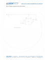
USER S MANUAL
Rectifier 1
10 A/10
48 V for Kliar Line
Art. 3004052
Dichiarazione CE di Conformità
CE Conformity Declaration
TIPO DELLA MACCHINA:
RADDRIZZATORE 1
PRODUCT TYPE:
RECTIFIER 1
Modello/
Model
10 A/10
10 A/10
48 V PER KLIAR LINE
48 V FOR KLIAR LINE
3004052
Matricola/
Serial Number:
Anno di costruzione/
Manufacture year
Il
sottoscritto
Gianni
Poliero
Legale
rappresentante dell azienda LEGOR GROUP
Srl
DICHIARA
The undersigned Gianni Poliero,
representative of LEGOR GROUP Srl
legal
DECLARES
sotto la sua esclusiva responsabilità, che la
macchina, a cui la presente dichiarazione si
riferisce, è conforme alle prescrizioni delle:
under his sole responsibility that the machine,
to which this declaration relates, conforms to
following standards:
- 2006/95/CE, Direttiva Bassa tensione
- Directive 2006/95/EC, on Low voltage
equipment
- 2004/108/CE, Direttiva Compatibilità
elettromagnetica
- Directive 2004/108/EC, on Electromagnetic
compatibility
- 2002/95/CE, Direttiva ROHS
- Directive 2002/95/EC, on ROHS
Bressanvido (Vicenza),
LEGOR GROUP Srl
Legale Rappresentante /
Legal Representative
Table of Contents:
Chapter
1.
General Description of the Machine
2.
Operation & Control Stations
3.
Protections and Safety Precautions
4.
Important Machine Technical Data Card
5.
Use of the Machine
6.
Movement and Transportation of the Machine
7.
Installation of the Machine
8.
Assembly/Disassembly of the Machine
9.
Set Up of the Machine
10.
Commissioning of the Machine
11.
Maintenance and Repair
12.
Attached Technical Documentation
13.
Information on Machine Noise Pollution
CHAPTER 1
GENERAL DESCRIPTION OF THE MACHINE
1.1
OPERATING PRINCIPLES AND MAIN TECHNICAL CHARACTERISTICS
LEGOR GROUP galvanising machines are built for the galvanisation of goldsmith
objects, costume jewellery, watch-making pieces and precision mechanics.
The objects to be galvanised are treated in the machines before being degreased and
performing other jobs such as rhodium, gold, platinum or palladium plating.
Degreasing is generally performed by placing the objects in the tank the furthest to the
right on the machine, where there is a degreasing/pickling solution, whose action is
activated by the passage of electric current.
The other galvanic treatments, on the other hand, can be performed in the other tanks,
by placing the objects in the electrolytic solutions and running the appropriate working
current through them.
The most important technical characteristics of our galvanising machines are:
Digital instrumentation
Programmable work timer
10 48 V / 25 A current rectifiers
110V available on request
Modest weight and dimensions
Totally made of stainless s
NOTE: The process should develop vapours during operation, due to the
electrolytic galvanisation; therefore they must be placed in a working
environment equipped with an adequate suction hood
1.2 Machine architecture:
1.2.1 Introduction:
The machines are made up of:
A main body containing all of the machine parts.
Anodic cable (red cord).
Cathodic cable (black hook cord).
Power cable.
1.2.2 Make up of the machine:
A0) Machine Body.
The machine body is made from stainless steel and contains all of the machine parts.
The partitions are closed and tools are required to access the inside. The machine is
installed on a flat surface and is made stable with four 2 cm feet. The body of the
machine is made of stainless steel and has no cutting parts or sharp corners that are
dangerous for the operator.
A1) General description of the machine
B) Anodic and Cathodic Electrodes.
The machine is equipped with a red cable collected to the anode and a black cable
collected to the cathode aside red and black clips.
C) Power cable.
The machine is equipped with a power cable with plugs for connection to the socket on
the rear of the machine body and for connection to the mains, which must be present in
the place where the machine is installed.
1.3 WARNINGS.
It is necessary to read this manual carefully before proceeding with installation,
commissioning, adjustment and maintenance of the machine. All of the operations
described in this manual are correct, the manufacturer does not accept any
responsibility for operations performed in a manner that is not in conformity with the
instructions or operations not envisioned in this manual.
In the event of breakdown or malfunction of the machine, apply to an authorized
technical centre or to the manufacturer. The manufacturer declines any responsibility
for damages to persons or property or accidents due to failure to observe the
prescriptions relative to safety, due to improper use or tampering with the machine. The
safety norms described in this manual integrate and do not supersede or replace the
norms in force locally, which must be observed by users in any case.
CHAPTER 2
OPERATION & CONTROL STATION
2.1 GENERAL
The machine is used as a workstation. All controls to start and adjust the machine are
located on the front panel in a convenient position for the operator.
2.2 SETTING UP THE WORK AND CONTROL STATION
The machine must be placed on a flat surface to prevent the risk of turnover. On
request, a suitable metallic platform may be provided to support the machine.
The installation must be performed in a dry, well-aired and correctly illuminated
environment. Additionally, there must be an appropriate water system near the place
where the machine is installed to permit ultrasonic water flow connection and cleaning
of the tanks.
NOTE: The solutions should develop vapours during operation, due to the
cataphoretic process, therefore it must be placed in a working environment
equipped with an adequate suction hood.
An appropriate disposal system MUST be provided for the drainage of the galvanic/ecoating solutions utilised, in harmony with the instructions supplied with the relative
liquids.
CHAPTER 3
PROTECTIONS
AND
SAFETY
PRECAUTIONS
OPERATORS AND MAINTENANCE PERSONNEL
FOR
The machine must not produce an average weighted noise A above 80 dB. The
machine has NO rotating parts that could come into contact with the operator.
The liquids used in the cataphoretic process are made in a low concentration
chemicals; in any case the operator must wear appropriate Personal Protective
Clothing (apron, gloves, goggles).
The operator must read the instructions and prescriptions provided with the
products utilized carefully.
It is a good practice for the operator to refrain from smoking and eating or drinking near
the
machine.
CHAPTER 4
IMPORTANT MACHINE TECHNICAL DATA CARD
External dimensions
mm
(300 x 175 x 300)
Weight
kg
12.5
Power tension
V
230 Vac single phase 50-60 Hz
Adjustment of galvanic tension and
distributable current
V
10-48 V
Timer
m
90 minutes
25 A
CHAPTER 5
MACHINE USE
5.1 INTENDED USE OF THE MACHINE.
This machine was built for the cataphoretic (e-coating) treatment of goldsmith objects,
costume jewellery, watchmaking pieces and precision mechanics.
PRECAUTIONS:
When the machine is operating the smoke suction and disposal system must be on
(suction hood, which must be installed at the worksite).
The operator must wear protective clothing, goggles and gloves and any other
protective clothing envisioned on the technical cards of the components used for the
galvanic baths; the machine must not be tampered with.
Use only e-coating solutions supplied by the manufacturer.
Do not place objects and/or excess liquid in the tanks, as this could cause dispersion of
the corrosive toxic liquid.
If this occurs, carefully follow the instructions shown on the technical cards
accompanying the products used and, in any case, thoroughly clean the areas involved
immediately.
To clean surface areas where galvanic or e-coatings liquids have been spilled, the
operator must wear appropriate individual protective clothing: (gloves, apron, goggles,
protective mask for the respiratory system).
Connect the machine to an electrical system in conformity with legal norms.
Dispose of used galvanic or e-coating liquids in accordance with the indications shown
on the relative technical cards for the solutions used.
5.2 CORRECT USE OF THE MACHINE
The machine is used by operating the controls and in situations of emergency it can be
stopped at any time, by turning the general power switch to the O position.
NOTE:
The solutions used for the e-coatings, plating, degreasing and neutralization must be
purchased ready made in order to ensure safe and valid processing.
Alternatively, the solutions can be prepared by the operator, in which case the
instructions shown on the technical cards of the products used must be followed.
Before placing the solutions in the respective tanks, they must be mixed.
Place enough solution in the tanks to cover the electrodes.
The solutions must be placed in the tanks when the machine is prepared and when
they are exhausted they must be replaced.
OPERATIONAL STEPS TO OBTAIN PERFECT FINAL RESULTS
1. Degreasing with ultrasounds
2. Rinsing in demineralised water
3. Electrolytic degreasing
4. Rinsing in demineralised water
5. Neutralisation/activation
6. Rinsing in demineralised water
7. E-coating treatment (with Kliar-Line products)
8. First recovery in demineralised water
9. Second recovery in demineralised water
10. Rinsing in demineralised water
11. Dip the items into the Rinse Aid solution
12. Dry on air for 5-30 mins
13. Cure the items in a furnace/oven at 120-150°C for 30
mins.
1) Initial preparation of objects to be treated. (Degrasing with ultrasonic system
or by electrolytic process)
The objects must be carefully washed using the integrated ultrasonic washing tank,
and then rinsed (operational steps 1 and 2)
2) E-coating treatment
Check to make sure the suction hood is operating.
Lift the cover and ensure the machine is on by checking the general ON/OFF switch
(1). Hang the object on the hook on the negative electrode (cathode) and immerge it in
the e-coating bath. Adjust the tension with the potentiometer (4), verifying the value set
on the digital voltmeter (2) on the panel.
If the timer has been activated with the (5) switch, adjust it (6) to start the e-coating
process. Once the process has terminated, go on to the successive phases of rinsing
(operational steps 8, 9, 10, 11 and 12).
Important note: Remove the objects from the e-coating solution before cutting off the
tension in the bath.
3) Stop the processing cycle.
Turn off the machine off with the general switch (1).
5.3 UNINTENDED USE OF THE MACHINE
It is not reasonable to envision a different use of the machine than the one for which it
was designed, of galvanic treatment.
5.4 INCORRECT USE OF THE MACHINE
Operating the machine in a manner other than as specified in point 5.2 of Chapter 5
constitutes incorrect use.
CHAPTER 6
MOVEMENT AND TRANSPORTATION OF THE MACHINE
The machine has dimensions and a weight that permits simple movement using
mechanical lifts. To transport the machine, place it in the original packaging or in other
suitable packaging, with the parts in polystyrene foam; make sure the upper part of the
machine is oriented towards the top when performing the transportation. Move the
machine with a suitable lift for transportation. Load only the packed machine on the lift
and do not place other objects on top of it, inasmuch as they could damage the
machine or fall; do not load the machine on top of other objects because there could be
a situation of precarious balance during transportation. Check to make sure that all
machine parts are properly fixed and cannot move during transportation prior to starting
transportation.
CHAPTER 7
INSTALLATION OF THE MACHINE
7.1 GENERAL
The machine may operate in conditions of safety and with the best results if it is
correctly installed in the working environment.
7.2 MECHANICAL INSTALLATION
The machine must rest on a perfectly flat surface, on a dry and clean surface. The
machine may have the rear side against a wall, even if it is advisable to leave enough
room around the machine, at least 1 m, in order to facilitate performance of all of the
cleaning operations, without having to move the machine.
Additionally, it is advisable to have a larger free area on the front side of the machine to
facilitate the operator s work.
The installation plan of the machine is shown in Annex I.
7.3. ELECTRICAL CONNECTION
The machine must be connected to the mains for electrical power. The electrical
system must be in compliance with safety norms in force and satisfy the requirements
of noninflammability. Before electrical connection, it is necessary:
Ensure that the information relative to the power line corresponds to the indications
on the machine identification plaque and the electric panel, as well as with the data
shown in Chapter 4 of this manual;
Ensure that the power cables have a diameter of at least 2.5 mm2.
Ensure that an automatic magneto-thermal switch is place up line from the electrical
circuit socket and that the circuit has the ground connection correctly connected to
the power socket, which must be of a suitable type for connection with the plug on
the machine cable.
Make sure the machine power is not on.
To turn on the power plug the power cable into the plant socket.
In the event of breakdown or malfunction, apply to qualified personnel.
CHAPTER 8
ASSEMBLY/DISASSEMBLY OF THE MACHINE
8.1 INITIAL ASSEMBLY OF THE MACHINE
The machine is supplied ready for operation.
The only task to perform is to connect the electrodes with anodes and the items to be
treated through the conductive clips.
CHAPTER 9
PREPARATION OF THE MACHINE FOR COMMISSIONING
9.1 GENERAL
The machine is supplied ready for operation.
9.2 CHECK FOR ANY DAMAGE THAT MAY HAVE BEEN SUSTAINED BY THE
MACHINE.
When the packaging is removed from the machine, carefully inspect every part to
ensure that it has not been damaged during transportation. If damages are discovered,
contact the carrier first, then the seller or the manufacturer. Also ensure that the
machine has been received, complete with all of its parts.
9.3 REMOVAL OF BLOCKS
The machine is delivered without blocked parts; therefore no removal of blocks is
required.
9.4 CLEANING THE MACHINE
Before commissioning the machine, clean it carefully, removing dust and any foreign
substances. It is advisable for the operator to use gloves, goggles and to wear an
apron when cleaning the machine. Use a soft cloth to clean the machine and, possibly,
with plastic spatulas and tools in order to avoid streaking the tanks or other parts.
9.5 CONNECTION OF THE MACHINE TO THE ELECTRICITY NETWORK
Ensure that the information relative to the power line corresponds to the indications on
the machine identification plaque and the electric panel, as well as with the data shown
in Chapter 4 of this manual. Before performing the connection, make sure the electrical
components to be worked on are not powered. Plug the power cable into the socket on
the side of the machine and in the socket provided in the working area.
9.7 ADJUSTMENT OF THE MACHINE
The machine requires no preliminary adjustment in order to start operation.
CHAPTER 10
COMMISSIONING OF THE MACHINE
10.1 COMMISSIONING OF THE MACHINE
Adhere to the following instructions in order to commission the correctly installed
machine:
Position the differential switch located up line from the machine in the closed
position.
The operator must wear the individual protective devices foreseen for the work
performed. He must then position himself in a manner to ensure perfect visibility
and within easy reach of all signals and controls.
10.2 USE OF THE MACHINE
Refer to paragraph 5.2 for instructions on the correct use of the machine.
CHAPTER 11
MAINTENANCE AND REPAIR
11.1. MAINTENANCE
General
The machine requires no particular maintenance, except for cleaning the machine
itself. The machine functions well only if the various parts are clean.
Maintenance of electrical connections.
The electric power cable must be checked periodically and replaced if it is not in good
repair.
Changing fuses.
The machine is protected with a 5A 220V ca fuse.
The fused is housed in a box in the mains socket placed on the side of the machine
body.
Follow these instructions to replace the fuse:
Turn the machine of with the general power switch on O;
Cut off the machine from the mains socket by disconnecting the power cable from the
network socket and the socket on the rear of the machine.
Open the door, remove the blown fuse, insert a new fuse and close the door.
Connect the network cable to the machine and the network socket.
Turn the power switch on and check the to make sure the green indicator light comes
on.
If the machine fails to function, apply to the seller or to the manufacturer.
11.2 REPAIRS
The operator must not perform any repairs; in the event of breakdown, apply to the
seller or manufacturer.
CHAPTER 12
ATTACHED TECHNICAL DOCUMENTATION
12.1 LIST OF ATTACHED DOCUMENTS
The following documents are attached to this publication and are an integral part of it.
Annex I: Diagram of electrical circuit of the machine
CHAPTER 13
INFORMATION ON MACHINE NOISE POLLUTION
13.1 IMPORTANT VALUES
The average weighted A noise pollution is less than 70 dB.
Annex I: Diagram of electrical circuit of the machine