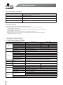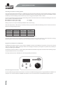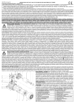
1
IT/EN
ISTRUZIONI PER L’USO E
LA MANUTENZIONE
USE AND MAINTENANCE
INSTRUCTIONS
VERSIONE ORIGINALE IN LINGUA ITALIANA
VERSIONE TRADOTTA IN LINGUA INGLESE
INDICE
Capitolo
1
1.1
Istruzioni di sicurezza
Note CE
4
2
2.1
2.2
Generalità
Funzioni ed opzioni
Identificazione
6
3
3.1
3.2
Installazione
Montaggio
Condizioni ambientali
Dimensioni di ingombro
Installazione meccanica
Collegamenti elettrici
Diagramma delle connessioni standard
Terminali di potenza
Terminali di controllo
Terminali espansione I/O
Terminali espansione RS485
Terminali espansione Can Bus
Gestione opzione frenatura Smartdrive
8
4
Utilizzo del tastierino
21
5
Descrizione parametri
22
6
Protocollo Canbus
26
7
Diagnostica
27
8
Allarmi e risoluzione
28
9
Smaltimento
29
5
6
7
8
8
9
10
12
12
13
15
19
19
19
20
3
www.motovario.com
1. ISTRUZIONI DI SICUREZZA
Si raccomanda di leggere attentamente questo manuale prima di installare e/o avviare lo Smartdrive e di attenersi scrupolosamente alle
istruzioni riportate in termini di sicurezza.
Le informazioni inerenti la sicurezza saranno evidenziate con due simboli che ne definiscono la pericolosità:
Simbologia
Attenzione
Si richiede al personale installatore o utilizzatore dello Smartdrive di prestare attenzione ad una
situazione che potrebbe recare rischi fisici minori e/o danneggiamento del prodotto.
Pericolo
Si richiede al personale installatore o utilizzatore dello Smartdrive di prestare particolare attenzione
ad una situazione che potrebbe recare seri rischi fisici ed eventualmente alla morte.
Come utilizzare lo Smartdrive in sicurezza
Pericolo di shock elettrico. Lo Smartdrive viene connesso a linee con elevata tensione. Effettuare tutte
le operazioni di installazione solo in assenza di tensione.
Lo Smartdrive deve essere installato e manutenzionato tramite una pedana isolata solo da
personale specializzato.
Lo Smartdrive deve essere alimentato da una linea protetta da dispositivi per la sovracorrente, per il
cortocircuito e per la dispersione verso terra in ottemperanza alle disposizioni previste dalle normative
di sicurezza, sebbene la corrente di dispersione verso terra sia inferiore ai 3.5mA in c.a. o 10mA in c.c. .
Lo Smartdrive deve essere alimentato dopo aver chiuso il coperchio.
Tolta l’alimentazione allo Smartdrive, sui componenti restano livelli di tensione pericolosi.
Pertanto prima di effettuare operazioni di manutenzione attendere almeno dieci minuti.
Lo Smartdrive è utilizzato generalmente per movimentare parti meccaniche. L’utilizzatore ha la responsabilità
di assicurare che questi movimenti meccanici non si traducano in condizioni di pericolo.
4
USO E MANUTENZIONE SMARTDRIVE
Connessioni a terra
Non è consentito l’utilizzo dello Smartdrive senza le adeguate connessioni a terra.
Il filo di terra del cavo di alimentazione deve essere sempre connesso al morsetto di terra (PE) della
scheda di potenza dello Smartdrive.
Il filo di terra del coperchio deve essere sempre connesso al faston di terra (PE) della scheda di potenza
dello Smartdrive.
Mantenere separato il filo di terra del cavo di alimentazione dello Smartdrive da quella di altre
apparecchiature elettriche di potenza e non creare in alcun modo anelli di terra .
Fusibili di protezione
Lo Smartdrive è sprovvisto di fusibili di protezione, quindi deve essere alimentato da una rete protetta
da dispositivi per la sovracorrente, per il cortocircuito e per la dispersione verso terra in ottemperanza
alle disposizioni previste dalle normative di sicurezza p.e. attraverso l’utilizzo di interruttori differenziali,
interruttori magnetotermici, interruttori sezionatori con fusibili standard riportati in tabella:
MODELLO
POTENZA INVERTER
TENSIONE / CORRENTE FUSIBILE
SU INTERRUTTORE SEZIONATORE
IM2015F#4
1,5 kW
250 Vac / 8 A
IM4315F#4
1,5 kW
500 Vac / 6,3 A
IM4322F#4
2,2 kW
500 Vac / 10 A
IM4337F#4
3,7 kW
500 Vac / 15 A
1.1 NOTE CE
Utilizzando gli Smartdrive nei paesi della Comunità Europea è necessario attenersi alla norma CEI EN 61800-3 del 2004 sulla compatibilità
elettromagnetica ed alla norma CEI EN61800-5-1 del 2005 sulla Sicurezza elettrica che definiscono:
Categorie degli ambienti
Primo Ambiente
Tutti gli ambienti che sono direttamente riforniti attraverso una linea pubblica di alimentazione a bassa tensione: officine, laboratori,
piccola produzione, appartamenti, case e servizi pubblici collettivi.
Secondo Ambiente
Ambiente industriale avente la propria rete di alimentazione non direttamente collegata alla linea pubblica di alimentazione a bassa
tensione. È presente un trasformatore per la rete di media tensione.
Categorie degli azionamenti elettrici
Categoria C1 azionamenti elettrici con tensione nominale inferiore a 1000 V, per Primo Ambiente.
Categoria C2 azionamenti elettrici con tensione nominale inferiore a 1000 V; si tratta di dispositivi non di tipo plug-in, né mobili, che
relativamente all’uso nel Primo Ambiente devono essere installati e messi in funzione esclusivamente da personale qualificato.
Categoria C3 azionamenti elettrici con tensione nominale inferiore a 1000 V, adatti al Secondo Ambiente, ma non al Primo Ambiente.
5
www.motovario.com
Definizione dei gradi di inquinamento
GRADO DI INQUINAMENTO
1
2
3
4
DESCRIZIONE
Nessun inquinamento, o solo inquinamento asciutto, non conduttore.
L’inquinamento non ha influenza.
Normale solo inquinamento non conduttore. Occasionalmente, tuttavia, è prevedibile
una conducibilità temporanea dovuta alla condensa, quando il PDS non è in funzione.
Inquinamento conduttore o asciutto non conduttore che diviene conduttore a causa
della condensa prevista.
L’inquinamento genera una conducibilità persistente dovuta, per esempio, alla polvere
conduttrice, alla pioggia o alla neve.
Categoria di sovratensione
Valida per le apparecchiature alimentate dalla rete, vi sono quattro categorie:
• La categoria IV si applica ad apparecchiature permanentemente connesse all’origine dell’impianto ( a monte del quadro
principale di distribuzione).
• La categoria III si applica ad apparecchiature permanentemente connesse agli impianti fissi ( a valle o comprese nel quadro
principale di distribuzione).
• La categoria II si applica ad apparecchiature non permanentemente connesse all’impianto fisso.
• La categoria I si applica ad apparecchiature collegate ad un circuito in cui sono state adottate misure per ridurre le sovratensioni
temporanee ad un livello basso.
2. GENERALITÀ
2.1 FUNZIONI ED OPZIONI
MOTOINVERTER VETTORIALE SENSORLESS
Uscita
Alimentazione
Prestazioni
Funzionamento
Ingressi
Uscite
Protezioni
Condizioni
Operative
Schede Opzionali
6
MONOFASE
TRIFASE
Grandezza motore IEC
Max potenza nominale motore
Corrente nominale inverter
Tensione
Frequenza
Tensione (Vin)
Frequenza
Compatibilità EMC
Metodo di controllo
Risoluzione frequenza
Accuratezza Velocità
Tempi di risposta
Capacità sovraccarico
Tempi di acc. / dec.
Frequenza portante PWM
Boost di tensione
Metodo di controllo e riferimento di
velocità
63-71-80
71-80-90-100
71-80-90-100-112
0,75 kW
1,5kW
3kW
3,4 A
3,75 A
9,25A
0 ÷ Vin trifase
0 ÷ 200 Hz
230 V ± 15% Monofase
400V ± 15% Trifase
47 ÷ 63 Hz
Classe C2 secondo EN 61800-3
Vettoriale sensorless
0,1 Hz
5%
10 ms
da 2 a 50 Hz: 150% per 60 S, 200% per 1 s
0,1 ÷ 599,9 s
5 KHz
Automatico
Tastiera On-Board / Tastiera remota / Ingressi HW / Seriale / Ingresso analogico
/ Potenziometro
Ingressi
4 digitali multifunzione opto-isolati (PNP, alimentazione esterna o autoalimentazione)
Alimentazione e controllo freno corrente continua 103 Alimentazione e controllo freno corrente continua 178
Vcc ± 15% (metodo di pilotaggio a singola semionda) Vcc ± 15% (metodo di pilotaggio a singola semionda)
Controlli
Sovratensione - Sottotensione - Sovraccorrente - Sovraccarico - Sovratemperatura
7mo IGBT resistenza frenatura
No
Si
Temperatura ambiente di lavoro
-5 °C / +45 °C
Temperatura ambiente di stoccaggio -15 °C / +80 °C
Umidità relativa
20 ÷ 85 % senza condensa
Altezza s.l.m.
0 ÷ 1000 m s.l.m.
Sistema di raffreddamento
Naturale - Ventilazione motore
1 uscita relay 24Vdc 3A
1 uscita analogica 0÷5Vdc
Scheda I/O (3 funzioni)
1 ingresso analogico impostabile tramite dipswitch 0÷5Vdc, 0÷10Vdc o 0÷20mA
Scheda RS-485 con protocollo MODBUS
Scheda CANBUS con protocollo proprietario
Uscite
USO E MANUTENZIONE SMARTDRIVE
2.2 IDENTIFICAZIONE
Controllare che lo Smartdrive non si sia danneggiato durante il trasporto.
Controllare che lo Smartdrive consegnatoVi sia effettivamente quello richiesto.
Controllo dell’etichetta QC (Quality Control)
L’etichetta QC identifica univocamente l’ Inverter fornendo le caratteristiche primarie del modello richiesto. Essa costituisce il marchio
della qualità di Motovario garantendo che tutte le migliori procedure di collaudo siano state effettuate sul prodotto.
codice Motoinverter
cod. 202.000P08000078
versione software
sw
serial number
sn
Cl.
codice cliente
Controllo della targhetta di identificazione Inverter
Posta all’esterno della scatola portainverter, riassume le caratteristiche elettriche, di protezione, rintracciabilità ed avvertenze sul medesimo:
Grado di protezione
Corrente nominale d’uscita
Tensione di alimentazione
Modello Inverter
Potenza Inverter
Frequenza di alimentazione
Numero di serie
Designazione del modello
IM 2 0 07
Serie inverter
2
4
CLASSE DI VOLTAGGIO
220 Vac
400 Vac
0
3
N° FASI DI ALIMENTAZIONE
Monofase
Trifase
Classe di voltaggio
N° fasi di alimentazione
Massima potenza motore applicabile
POTENZA MOTORE
07
15
37
0,75 kW
1,5 kW
3,0kW
7
www.motovario.com
Lo Smartdrive può essere alimentato con reti standard trifasi, simmetriche elettricamente rispetto
alla terra (reti TN o TT). In casi di alimentazione tramite reti IT, si richiede l’utilizzo di un trasformatore
triangolo/stella, con terna secondaria riferita a terra.
3. INSTALLAZIONE
3.1 MONTAGGIO
Condizioni ambientali
Lo Smartdrive va installato su superfici resistenti al fuoco. In caso contrario esiste pericolo di incendio.
Non collocare nelle immediate vicinanze dello Smartdrive materiali infiammabili. In caso contrario
esiste pericolo di incendio.
Installare lo Smartdrive non direttamente esposto alla luce del sole e in un ambiente ben areato.
Se lo Smartdrive deve essere installato all’interno di una macchina per temperatura ambiente si intende
quella interna alla macchina.
Condizioni operative
GRADO DI INQUINAMENTO
DESCRIZIONE
Temperatura ambiente di lavoro
(-5 ÷ 45) °C
Temperatura ambiente di stoccaggio
(-15 ÷ 80) °C
Umidità relativa (ambiente di lavoro e di stoccaggio)
(20 ÷ 85) % senza condensa o congelamento
Altitudine
fino a 1000 m s.l.m. senza deriva
Vibrazioni Vibrazioni
fino a 5,9 m/s²
IP
54 (55 senza potenziometro on-board)
Sistema di raffreddamento
naturale
8
USO E MANUTENZIONE SMARTDRIVE
Dimensioni ed ingombro
P
H
L
VERSIONE
INVERTER
MONOFASE
TRIFASE
GRANDEZZA
MOTORE
L
H
P
PRESSACAVO PER CAVO
DI ALIMENTAZIONE
TAPPO PER CAVO
DI CONTROLLO
(predisposto per pressacavo)
063
194
190
156
M20x1.5
M16x1.5
071
194
200
156
M20x1.5
M16x1.5
080
194
205
156
M20x1.5
M16x1.5
071
256
195
202
M25x1.5
M16x1.5
080
256
204
202
M25x1.5
M16x1.5
090
256
205
202
M25x1.5
M16x1.5
100
256
214
202
M25x1.5
M16x1.5
112
256
229
202
M25x1.5
M16x1.5
9
www.motovario.com
Istruzioni d’uso e manutenzione motore elettrico
Conformità alle Direttive Europee – marcatura CE
I motori elettrici asincroni trifase e monofase in esecuzione standard serie TS e TH impiegati su Smartdrive sono conformi alla norma
costruttiva armonizzata IEC 60034-1 e quindi corrispondono a quanto previsto dalla Direttiva Bassa Tensione 2006/95/CE. Il motore
elettrico, considerato come componente, è conforme alle seguenti direttive:
- Direttiva ROHS 2002/95/CE riguardante la limitazione dell’uso di sostanze dannose negli equipaggiamenti elettrici ed elettronici.
- Direttiva EMC 2004/108/CE riguardante le caratteristiche intrinseche relative all’emissione e ai livelli di immunità.
Tutti i motori in esecuzione standard funzionanti in servizio continuo e alimentati da rete sono conformi alle norme generali EN50081
(limiti di emissione per ambienti civili) e EN50082 (immunità per ambienti industriali); nel caso di motori autofrenanti (suffisso –B) con
freno in corrente continua Smartdrive è in grado di alimentare un freno a 103Vcc nella versione monofase e a 178Vcc nella versione
trifase. Qualora si voglia alimentare separatamente il freno si può usare il raddrizzatore di corrente a semionda, il gruppo raddrizzatorebobina freno è conforme alle norme suddette tramite l’uso di raddrizzatore con filtro antidisturbo (NBR); nel caso di raddrizzatore a
semionda sblocco rapido (SBR) o a semionda frenata rapida (RSD) o a semionda sblocco e frenata rapida (RRSD) il filtro viene realizzato
collegando in parallelo all’alimentazione in alternata un condensatore 440Vac 0,22mF classe X2 secondo EN132400.
Tutti i motori elettrici, in quanto componenti, sono destinati ad essere incorporati in apparecchi o sistemi completi e non devono essere
messi in servizio fino a quando i macchinari ai quali sono stati incorporati non siano stati resi conformi alla Direttiva Macchine (Certificato
di Incorporazione - Direttiva 2006/42/CE).
La responsabilità della conformità alla Direttiva Macchine e Direttiva EMC di un’installazione completa è a carico del costruttore
della macchina.
Si raccomanda di leggere attentamente le istruzioni che seguono prima della messa in servizio; ogni operazione di
installazione, messa in servizio, manutenzione e protezione del motore deve essere eseguita da personale qualificato nel
rispetto di tutte le disposizioni legislative e norme tecniche vigenti nonchè delle prescrizioni in termini di sicurezza per
l’equipaggiamento elettrico delle macchine secondo quanto dichiarato dalla norma europea EN60204-1. Si rammenta che
la presente documentazione integra e non sostituisce alcuna disposizione legislativa o normativa tecnica o prescrizione di
sicurezza inerente il motore elettrico. Si declina ogni responsabilità derivante dall’uso improprio e dal mancato rispetto
delle normative in termini di sicurezza e comunque vigenti nella CEE riguardanti il motore elettrico.
Installazione Meccanica
Prima dell’installazione verificare che: lo Smartdrive non sia visivamente danneggiato (danni
derivanti da trasporto o immagazzinaggio); i dati di targa siano congruenti con le caratteristiche d’uso
del motore e l’applicazione a cui è destinato; la tensione di alimentazione corrisponda alla tensione
di rete; la temperatura ambiente sia compresa tra -15°C e +40°C; l’altitudine sia <1000 metri s.l.m.;
condizioni di temperatura ambiente e/o altitudini superiori implicano l’applicazione di un fattore
correttivo della potenza (vedasi catalogo di prodotto); il grado di protezione IP indicato sul motore
elettrico sia idoneo all’ambiente secondo IEC34-5. Nel sollevamento del motore utilizzare i punti
previsti; i golfari presenti sui motori servono al sollevamento del solo motore e non di altre macchine
ad esso accoppiate; controllare che gli organi da collegare al motore siano congruenti con i dati del
motore elettrico.
Lavori preliminari: rimuovere eventuali bloccaggi o protezioni usate per il trasporto (es. protezione
estremità di uscita albero motore) e verificare che l’albero motore ruoti liberamente nella sua sede
(per motori autofrenanti, suffisso –B; la verifica è possibile solo agendo sulla leva di sblocco manuale,
ove presente); pulire accuratamente le estremità d’albero in modo da rimuovere qualsiasi traccia di
sostanza anti-corrosiva, contaminante o simile, usando un normale solvente; impedire che il solvente
penetri nei cuscinetti o nelle guarnizioni dell’albero, per non danneggiarli; verificare, in particolare
dopo un lungo periodo di stoccaggio, che il motore non abbia assorbito umidità, misurando che la
resistenza di isolamento sia < 10MΩ a 20°C; la misura deve essere eseguita applicando una tensione
continua di 500V tra le fasi verso terra; gli avvolgimenti devono essere scaricati immediatamente dopo
la misura. Se la resistenza di isolamento non è sufficiente il motore deve essere asciugato mediante
aria calda oppure tramite trasformatore di isolamento collegando gli avvolgimenti di ogni fase in serie
e applicando una tensione alternata ausiliaria pari al 10-20% di quella nominale, fino ad ottenere un
valore di resistenza sufficiente.
10
USO E MANUTENZIONE SMARTDRIVE
Installazione: si raccomanda di fissare adeguatamente lo Smartdrive in funzione delle masse, tipo
di montaggio ed esecuzione; eseguire il montaggio su base piana, rigida, esente da vibrazioni,
resistente alle deformazioni; allineare con cura lo Smartdrive e la macchina comandata per evitare
sforzi inammissibili sull’albero motore, osservando i carichi radiali e assiali massimi ammessi (vedasi
catalogo motori elettrici); un disallineamento o un calettaggio forzato possono provocare durante
l’esercizio surriscaldamenti anomali mettendo a rischio la sicurezza; installazioni verticali devono
impedire la caduta di corpi estranei all’interno delle aperture di ventilazione (prevedere l’uso di
copriventola con tettuccio); durante il montaggio evitare danni ai cuscinetti usando come riscontro
l’albero motore previo smontaggio del copriventola; non sottoporre l’estremità d’albero ad urti o colpi;
l’albero del motore è equilibrato dinamicamente completo di mezza chiavetta a partire dalla gr.80,
grado di vibrazione normale; accertarsi che le parti da calettare successivamente sull’albero motore
siano equilibrate con mezza chiavetta; lo Smartdrive deve essere fissato in modo da consentire: la
lettura dei dati di targa; l’ispezione della scatola morsettiera; la pulizia dei vani motore; l’assenza di
parti in movimento all’esterno delle protezioni (es. copriventola); una sufficiente ventilazione, evitando
strozzature nei passaggi d’aria e l’ingresso di trucioli, polvere o liquidi e tutti i casi che compromettano
il regolare smaltimento del calore; in presenza di ambienti umidi, disporre possibilmente la scatola
morsettiera con l’entrata dei cavi collocata verso il basso; sia assente eventuale condensa; in presenza
di fori scarico condensa, scaricare la condensa, quindi reinserire i tappi per ripristinare il grado di
protezione IP; eseguire l’operazione con rete di alimentazione visibilmente sezionata; in presenza di
scaldiglie anticondensa, accertarsi che il motore non sia alimentato e non sia ancora in rotazione prima
di metterle in funzione; accertarsi inoltre che la tensione di alimentazione delle scaldiglie coincida con
la tensione specificata.
Installazione Elettrica e messa in servizio
Per collegare lo Smartdrive utilizzare dei capicorda del tipo isolati per garantire il rispetto delle distanze
minime tra parti in tensione e parti metalliche non attive; tutte le entrate di cavo non utilizzate
devono essere sigillate per ripristinare il grado di protezione IP. I cavi di alimentazione e di messa a
terra devono essere conformi alla regola d’arte e alle norme applicabili scegliendo cavi e conduttori
adeguati per portata e isolamento; il cablaggio delle connessioni e la sezione dei cavi devono essere
conformi a EN60204-1. In caso di motori autofrenanti, prima della messa in servizio verificare il corretto
funzionamento del freno e l’adeguatezza del momento frenante. Non toccare l’involucro del motore
durante la marcia in quanto le temperature di funzionamento possono raggiungere valori > 50°C.
Protezioni ogni circuito elettrico deve essere protetto contro danni derivanti da guasti o funzionamenti
anomali per sovracorrenti da cortocircuito, correnti di sovraccarico, interruzione/diminuzione della
tensione di alimentazione, velocità eccessiva degli elementi delle macchine, surriscaldamento
per frequenti avviamenti. Ai fini della sicurezza delle persone e/o cose devono essere predisposte
protezioni contro i contatti diretti e indiretti a causa di guasti all’isolamento. Nel caso di arresto della
rotazione dell’albero a mezzo di inversione di corrente, si devono prendere precauzioni per l’arresto
della rotazione in senso contrario; quando la sicurezza della macchina dipende dal senso di rotazione,
si devono prendere provvedimenti atti ad impedire un’inversione di fasi; il senso di rotazione deve
inoltre essere contrassegnato con etichetta in posizione visibile.
Manutenzione / ricambi prima di intervenire su Smartdrive o in zone limitrofe, sezionare
l’alimentazione dalla rete di potenza, attendere l’arresto delle masse in movimento, attendere che la
temperatura superficiale sia scesa sotto i 50°C per evitare pericoli di ustione.
Periodicamente verificare: l’assenza di eventuali depositi di polvere, olio, sporcizia su ventola e
copriventola; le condizioni dell’anello di tenuta; il serraggio delle connessioni; l’assenza di vibrazioni e
rumorosità. Nel caso di smontaggio di componenti non autorizzato dal costruttore, decade la garanzia
e non sono riconosciuti oneri a carico del costruttore stesso. Ordinare le parti di ricambio specificando
tipo motore, codice prodotto e numero di matricola indicati sulla targa di identificazione. Al termine
dei lavori di manutenzione e ispezione devono essere eseguiti controlli sulla sicurezza e funzionali
(protezione termica, freno, ecc.).
Immagazzinamento gli Smartdrive devono essere stoccati in ambienti temperati, asciutti, puliti, al
riparo da intemperie, in assenza di vibrazioni e/o urti. Le estremità d’albero devono essere protette con
vernice anticorrosiva o grassi (in caso di anello di tenuta, evitare il contatto con i protettivi).
11
www.motovario.com
3.2 COLLEGAMENTI ELETTRICI
È buona regola tenere separato il cablaggio dei circuiti di potenza da quello utilizzato per i circuiti di segnale.
Diagramma delle connessioni standard
Esempio di connessione con ingressi digitali PNP autoalimentati dallo stesso Smartdrive, con CanBus connesso ad un Touch Screen e con
Rs485 ModBus connesso ad un PC.
12
USO E MANUTENZIONE SMARTDRIVE
Terminali di potenza
Terminali di potenza per interno base scatola case A
La presente scheda richiede una alimentazione unicamente a 230Vac monofase con le connessioni
indicate in figura.
Con la presente scheda è possibile gestire un eventuale freno elettromagnetico (max 5A) incorporato
al motore attraverso una tensione continua non stabilizzata ricavata dalla 230Vac (Freno + e Freno -).
I segnali VA, VM, VP ed il cavo flat permettono la comunicazione e l’alimentazione tra le schede di
potenza e di controllo.
Terminali di potenza per interno base scatola case B
13
www.motovario.com
Terminali di potenza per interno base scatola case B
La presente scheda richiede, a seconda del codice dello Smartdrive in proprio possesso, una
alimentazione a 230Vac monofase, a 230Vac trifase oppure a 400Vac trifase con le connessioni
indicate in figura.
Con la presente scheda è possibile gestire una eventuale resistenza di frenatura esterna allo Smartdrive.
I segnali VA, VM, VP ed il cavo flat permettono la comunicazione e l’alimentazione tra le schede di
potenza e di controllo.
14
USO E MANUTENZIONE SMARTDRIVE
Terminali di controllo
Terminali di controllo per coperchio scatola case A
15
www.motovario.com
I Jumper per l’impostazione della seriale se sono entrambi in posizione 2-3 permettono l’utilizzo della scheda di Espansione Rs485.
Se sono entrambi in posizione 1-2 permettono l’utilizzo della scheda di Espansione CanBus.
La scheda di controllo della scatola avente case A possiede di base 4 ingressi digitali.
I segnali VA, VM, VP ed il cavo flat permettono la comunicazione e l’alimentazione tra le schede di potenza e di controllo.
I 4 input digitali possono essere utilizzati con alimentazione esterna o interna (autoalimentazione):
• Caso 1 Alimentazione esterna tipo PNP
- da 12 a 24Vdc su l’input che si intende utilizzare
- 0Vdc su morsetto COM
• Caso 2 Alimentazione interna tipo PNP
- la 12Vdc interna (da autoalimentazione input digitali) sull’input che si intende utilizzare
- La massa interna (da autoalimentazione input digitali) su morsetto COM
INPUT MECCANICO
(PULSANTE, INTERRUTTORE, RELAY, ETC.)
SENSORE CON USCITA ON/OFF
ALIMENTAZIONE ESTERNA 12 VCC A 24VCC (VEXT)
ALIMENTAZIONE ESTERNA 12 VCC A 24VCC (VEXT)
ALIMENTAZIONE INTERNA 12VCC (VINT)
ALIMENTAZIONE INTERNA DEL SENSORE 12VCC
Connessione Encoder
Lo Smartdrive è idoneo sia a livello hardware che software a gestire un encoder incrementale di tipo PNP o Push-Pull 12Vdc 100mA
(max) con risoluzione compresa fra 13 e 2048 impulsi/giro e per velocità del motore comprese fra 60 e 3000 rpm. Sono predisposti
alla lettura delle Fasi A e B dell’encoder gli input 1 e 2. Per l’alimentazione del medesimo fare riferimento alla sezione precedente.
Non esiste la possibilità di retroazione via encoder incrementale line-driver.
Per utilizzare l’encoder sullo Smartdrive, bisogna effettuare la procedura descritta di seguito: dopo aver collegato l’encoder (fase A
dell’encoder all’input digitale 1, fase B dell’encoder all’input digitale 2), si dovrà settare il parametro C0, impostando tale parametro
come indicato a pagina 25, e successivamente riavviare lo Smartdrive.
Con inverter retroazionato da encoder, se si accede al menu C è necessario in seguito spegnere e riaccendere l’inverter per ripristinare
il corretto funzionamento (reset sistema).
16
USO E MANUTENZIONE SMARTDRIVE
Terminali di controllo per coperchio scatola case B
17
www.motovario.com
I Jumper per l’impostazione della seriale se sono entrambi in posizione 2-3 permettono l’utilizzo della scheda di Espansione Rs485.
Se sono entrambi in posizione 1-2 permettono l’utilizzo della scheda di Espansione CanBus.
La scheda di controllo della scatola avente case B possiede di base 4 ingressi digitali.
I segnali VA, VM, VP ed il cavo flat permettono la comunicazione e l’alimentazione tra le schede di potenza e di controllo.
I 4 input digitali possono essere utilizzati con alimentazione esterna o interna (autoalimentazione):
• Caso 1 Alimentazione esterna tipo PNP
- da 12 a 24Vdc su l’input che si intende utilizzare
- 0Vdc su morsetto COM
• Caso 2 Alimentazione interna tipo PNP
- la 12Vdc interna (da autoalimentazione input digitali) sull’input che si intende utilizzare
- La massa interna (da autoalimentazione input digitali) su morsetto COM
INPUT MECCANICO
(PULSANTE, INTERRUTTORE, RELAY, ETC.)
SENSORE CON USCITA ON/OFF
ALIMENTAZIONE ESTERNA 12 VCC A 24VCC (VEXT)
ALIMENTAZIONE ESTERNA 12 VCC A 24VCC (VEXT)
ALIMENTAZIONE INTERNA 12VCC (VINT)
ALIMENTAZIONE INTERNA DEL SENSORE 12VCC
Connessione Encoder
Lo Smartdrive è idoneo sia a livello hardware che software a gestire un encoder incrementale di tipo PNP o Push-Pull 12Vdc 100mA (max) con
risoluzione compresa fra 13 e 2048 impulsi/giro e per velocità del motore comprese fra 60 e 3000 rpm. Sono predisposti alla lettura delle Fasi A e
B dell’encoder gli input 1 e 2. Per l’alimentazione del medesimo fare riferimento alla sezione precedente.
Non esiste la possibilità di retroazione via encoder incrementale line-driver.
Per utilizzare l’encoder sullo Smartdrive, bisogna effettuare la procedura descritta di seguito: dopo aver collegato l’encoder (fase A dell’encoder
all’input digitale 1, fase B dell’encoder all’input digitale 2), si dovrà settare il parametro C0, impostando tale parametro come indicato a pagina 25,
e successivamente riavviare lo Smartdrive.
Con inverter retroazionato da encoder, se si accede al menu C è necessario in seguito spegnere e riaccendere l’inverter per ripristinare il corretto
funzionamento (reset sistema).
18
USO E MANUTENZIONE SMARTDRIVE
Terminali Espansione I/O
La scheda di espansione I/O possiede un ingresso
analogico (terminali +5Vdc, Ref In e Massa), una uscita
analogica (0÷5) Vdc (terminali Ref Out e Massa) ed una
uscita relai (Com, NC e NO) 3A 24Vdc.
L’ingresso analogico può essere configurato con i 3 dip:
1 OFF
1 ON
1 OFF
2 OFF
2 OFF
2 OFF
3 OFF
3 OFF
3 ON
(0-5) Vdc
(0-10) Vdc
(0-20) mA
Terminali Espansione Rs485
La scheda di espansione Rs485 possiede lo standard
di connessione Bus+, Bus- e Massa ed in aggiunta una
+5Vdc 100mA per alimentare il dispositivo esterno con
il quale dialoga in Rs485 lo Smartdrive.
Il protocollo di comunicazione è di tipo ModBus.
Terminali Espansione CanBus
La scheda di espansione CanBus possiede lo standard di
connessione CanH, CanL, shield e PE con alimentazione
di opto-isolamento interna. Si aggiungono CanV+ e
CanV- qualora l’alimentazione (12÷24Vdc) di optoisolamento fosse voluta esterna. In tal caso la scheda
deve essere configurata a livello hardware.
19
www.motovario.com
Gestione opzione frenatura Smartdrive
Un motore asincrono regolato in frequenza da un inverter, durante il proprio funzionamento e principalmente nelle fasi di
decelerazione si comporta da generatore. Per impedire che il bus dello Smartdrive possa raggiungere valori di tensione non
consentiti, può essere gestita una resistenza di frenatura esterna sulla quale viene convogliata l’energia in eccedenza generata
dal motore.
Pertanto la resistenza di frenatura viene fatta intervenire quando i valori di tensione non consentiti superano il valore impostato
al parametro L1 nel “menù Motovario”:
0 Smartdrive per alimentazione 230Vac
L1 = 380Vdc
0 Smartdrive per alimentazione 400Vac
L1 = 750Vdc
La resistenza di frenatura può essere gestita nei soli Smartdrive che possiedono la scatola con case B.
Qualora il valore del parametro L1 sia quello di fabbrica indicato precedentemente si possono definire i seguenti valori minimi di
resistenza RFren per la scelta della resistenza di frenatura:
SMARTDRIVE
RFREN MINIMA
L1
IFREN
IM2015F#4
55Ω
380Vdc
7A
IM4315F#4
110 Ω
750Vdc
7A
IM4337F#4
75 Ω
750Vdc
10A
Comunque il valore della resistenza di frenatura non può essere inferiore al rapporto di L1/Ifren.
Il valore della potenza della resistenza di frenatura da determinare dipende strettamente dall’applicazione. In particolare
dall’energia generata dal motore e dal tempo a cui verrà sottoposta a questa energia la resistenza di frenatura.
Utilizzo Del Tastierino (On-Board e Remote)
Il tastierino On-Board o Remote, assolve alla funzione di monitoraggio del funzionamento dello Smartdrive ed alla funzione di
variazione dei parametri per il funzionamento desiderato, insieme alla funzione digitale o analogica della variazione di frequenza.
Il tastierino fornisce inoltre la possibilità di effettuare lo start e lo stop al funzionamento dello Smartdrive.
Nel seguente capitolo vengono descritte le funzioni dei tasti, del display a 7 segmenti dei tastierini On-Board e Remote. Inoltre è
descritto il funzionamento del potenziometro.
L’ immagine sotto riportata riproduce un tastierino On-Board o remote con potenziometro.
Connessione del Tastierino Remote
L’utilizzo del Tastierino Remote e la funzione dei suoi tasti, è identico al Tastierino On-Board che è integrato all’interno dello
Smartdrive. Fa eccezione il suo collegamento con lo Smartdrive che prevede l’utilizzo di un cavetto di collegamento e della scheda
di espansione RS-485.
20
USO E MANUTENZIONE SMARTDRIVE
4. UTILIZZO DEL TASTIERINO
Funzioni dei tasti e del potenziometro
OPERAZIONE
SIMBOLO
DENOMINAZIONE
FUNZIONI
Tasto Stop
Utilizzato per il comando di STOP
dello Smartdrive consente:
• la normale funzione di arresto del motore;
• la funzione di uscita dai menù;
• la funzione di ingresso nei menù in
combinazione al tasto Up o Down;
• la funzione di reset degli allarmi.
Tasto Start
Utilizzato per il comando di START
dello Smartdrive consente:
• la normale funzione di partenza del motore;
• la funzione di ingresso nei sottomenù dei menù;
• la funzione di convalida e salvataggio
dei parametri.
Tasto Up
Consente di:
• incrementare il valore del parametro;
• incrementare il riferimento del potenziometro
digitale con parametro C0=2
• scorrere in avanti la visualizzazione dei menù
e sottomenù;
• la funzione di ingresso nel menù Utente in
combinazione al tasto Stop;
• la funzione di ingresso nel menù Monitor in
combinazione al tasto Down.
Tasto Down
Consente di
• decrementare il valore del parametro;
• decrementare il riferimento del potenziometro
digitale con parametro C0=2
• scorrere indietro la visualizzazione dei menù
e sottomenù;
• la funzione di ingresso nel menù Installatore in
combinazione al tasto Stop;
• la funzione di ingresso nel menù Monitor in
combinazione al tasto Up.
Potenziometro
Consente di variare la frequenza di rotazione
del motore in maniera analogica da un minimo
ad un massimo preimpostato.
21
www.motovario.com
5. DESCRIZIONE PARAMETRI
Nelle tabelle delle pagine seguenti vengono elencati e descritti tutti i parametri dello Smartdrive che possono essere visionati e/o
impostati attraverso il tastierino On-Board o Remote.
Nelle tabelle sono stati indicati intenzionalmente i parametri con descrizioni brevi per rendere
meno complessa la lettura del Manuale Istruzioni. Si raccomanda di effettuare un breve corso
presso la casa madre per avere maggiori informazioni.
Tutti i parametri sono elencati e raggruppati per menù, in modo che tutte le funzioni appartenenti allo stesso menù possono
essere viste come un unico insieme.
In elenco sono riportati di seguito i menù esistenti:
Menù Utente
(per l’operatore finale)
Menù dedicato all’impostazione dei parametri relativi all’utilizzo dello Smartdrive da parte
dell’operatore finale. Tutti i parametri sono contraddistinti dalla lettera U.
Menù Installatore
(per l’installatore)
Menù dedicato all’impostazione dei parametri relativi all’utilizzo dello Smartdrive da parte del
distributore, dell’installatore o del costruttore della macchina ed è accessibile solo tramite codice
d’accesso. Tutti i parametri sono contraddistinti dalla lettera C.
Menù Motovario
(per la casa madre)
Menù dedicato all’impostazione dei parametri relativi all’utilizzo dello Smartdrive da parte della casa
madre e non è accessibile. Tutti i parametri sono contraddistinti dalla lettera L (Low Level).
Diagnostica
(per l’installatore
o la casa madre)
Menù per la visualizzazione dei parametri di diagnostica (Rif. Cap. 7).
Menù Utente
Il “menù Utente” consente all’operatore finale di variare i parametri che intervengono sulle funzionalità innate dello Smartdrive.
Attraverso il tastierino On-Board o Remote è possibile accedere al “menù Utente” premendo contemporaneamente i tasti Stop e
Up nella visualizzazione principale (ossia quella di avvio) ed in condizione di “STOP “dello Smartdrive. Verrà richiesta una password
il cui valore “P000” si modifica con i tasti Up e Down.
Si ricorda che quando lo Smartdrive esce dalla casa madre, la password del “menù Utente” è sempre P123. Pertanto si richiede al
ricevimento del medesimo di variarla attraverso il parametro U5.
Per l’utilizzo successivo del tastierino On-Board o Remote fare riferimento al Cap. 4.
MENÙ UTENTE
Unità Misura
Default
Parametro
Descrizione
U0
Frequenza elettrica di Uscita
Hz
50.0
C1
C0
U1
Accelerazione
sec
10.0
0.1
599.9
U2
Decelerazione
sec
10.0
0.1
599.9
U3
Senso rotazione
-
For
For
Rev
U4
Riferimento di velocità
-
0
0
4
U5
Password menù utente
-
123
000
999
230
400
Min
Max
Il parametro U4 definisce a quale dispositivo lo Smartdrive deve fare riferimento per fornire la frequenza in uscita.
I valori possibili sono riportati nel Cap. 6 pag. 25 parametro C0. La variazione del parametro U4 comporta la modifica automatica
del parametro C0 e viceversa. I valori impostati all’interno dei paramentri U1 e U2 si riferiscono al tempo che impiega lo Smartdrive
rispettivamente a portarsi da 0 a 100 Hz (in fase di accelerazione), e da 100 Hz a 0, (in fase di decelerazione). In fase di accelerazione
nel caso di frequenza finale impostata dall’utente diversa da 100 Hz, il tempo che impiegherà lo Smartdrive per portarsi al valore
impostato sarà proporzionale a tale riferimento (Es. U1=5 sec. valore di frequenza finale 50 Hz, lo Smartdrive impiega 2,5 sec
per arrivare al valore di frequenza finale). In fase di decelerazione nel caso di frequenza di partenza diversa da 100 Hz, il tempo
che impiegherà lo Smartdrive per portarsi al valore valore di 0 Hz sarà proporzionale a tale riferimento (Es. U1=5 sec. valore di
frequenza 40 Hz, lo Smartdrive impiega 2 sec per portarsi a 0 Hz).
22
USO E MANUTENZIONE SMARTDRIVE
Menù Installatore
Il “menù Installatore” consente all’installatore di variare i parametri che intervengono sulle funzionalità di base dello Smartdrive.
Attraverso il tastierino On-Board o Remote è possibile accedere a questo menù premendo contemporaneamente i tasti Stop,
Up e Down nella visualizzazione principale (ossia quella di avvio) ed in condizione di “STOP “dello Smartdrive. Verrà richiesta una
password il cui valore “P000” si modifica con i tasti Up e Down.
Si ricorda che quando lo Smartdrive esce dalla casa madre, la password del “menù Installatore” è sempre P956. Pertanto si richiede
al ricevimento del medesimo di variarla attraverso il parametro C19.
Per l’utilizzo successivo del tastierino On-Board o Remote fare riferimento al Cap. 4.
MENÙ INSTALLATORE
Parametro
Descrizione
Unità Misura
Default
Min
Max
C0
Riferimento di velocità
-
0
0
4
C1
Frequenza elettrica Massima
Hz
80.0
0.0
L33
L33
C2
Frequenza elettrica Minima
Hz
2.0
0.0
C3
Tempo in secondi per power off pwm
sec
0
0
3
C4
Abilitazione power off pwm
-
SI
NO
SI
C5
Operatore/Monitor (NO/SI diagnostica)
-
MON
OPE
MON
C6
Abilitazione Retroazione motore (Vettoriale Sensored)
-
NO
NO
SI
C8
Non usato
-
-
-
-
C9
-
50
1
9999
C10
Impulsi a giro di retroazione motore
(Vettoriale Sensored)
Fattore proporzionale KP di retroazione motore
(Vettoriale Sensored)
-
0
0
9999
C11
Fattore integrale KI di retroazione (Vettoriale Sensored)
-
0
0
9999
C12
Frequenza di linea minima
Hz
10
1
9999
C13
Frequenza di linea massima
Hz
5000
1
9999
C14
Offset encoder
-
5
0
9999
C15
Impulsi a giro encoder
-
200
1
9999
C16
Escursione encoder
-
200
1
9999
C17
Boost (solo per la modalità V/F)
%
5
0
100
C18
Frequenza ove si ha 100% tensione
(solo per la modalità V/F)
Hz
50.0
0
L33
C19
Password
-
956
000
999
C20
Revisione Software
-
-
-
-
C21
Abilitazione Input 1
-
NO
NO
SI
C22
Livello Input 1
-
Alto
Bass
Alto
C23
Filtro Input 1
msec
10
0
9999
C24
Funzione Input 1
-
8
0
12
C25
Abilitazione Input 2
-
NO
NO
SI
C26
Livello Input 2
-
Alto
Bass
Alto
C27
Filtro Input 2
msec
10
0
9999
C28
Funzione Input 2
-
9
0
12
C29
Abilitazione Input 3
-
NO
NO
SI
C30
Livello Input 3
-
Alto
Bass
Alto
C31
Filtro Input 3
msec
10
0
9999
C32
Funzione Input 3
-
8
0
12
C33
Abilitazione Input 4
-
NO
NO
SI
C34
Livello Input 4
-
Alto
Bass
Alto
C35
Filtro Input 4
msec
10
0
9999
C36
Funzione Input 4
-
9
0
12
23
www.motovario.com
C37
Timeout retroazione
sec
2.0
0
599.9
C38
Abilitazione Output
-
SI
NO
SI
C39
Funzione Output
-
3
0
7
C40
Frequenza Output
Hz
50.0
0.0
L33
C41
Ritardo Output
sec
0.0
0
599.9
C42
Offset potenziometro
V/100
0
0
500
C43
Valore centrale potenziometro
V/100
0
0
500
C44
Potenziometro Min.
V/100
0
0
500
C45
Potenziometro Max.
V/100
500
0
500
C46÷C61
Storico Allarme da 1 a 16
-
-
-
-
C62
Azzeramento Storico Allarme
-
NO
NO
SI
C63
Indirizzo Modbus/Canbus
-
0
0
255
C64
Timeout Modbus/Canbus
sec/10
100
0
600
C65
Percentuale di sovraccarico
%/10
1500
1000
1500
C66
Tempo di sovraccarico
sec
30
10
600
C67
Velocità iniziale per sovraccarico
RPM
0
0
3000
C68
Velocità finale per sovraccarico
RPM
600
100
6000
C69
Numero coppie poli (solo per la modalità V/F)
-
1
1
128
C70
Tipo azionamento
-
0
0 (vect)
1(v/f )
C71
Frequenza intervento freno ELM
0.5
0.0
150.0
C72
Tempo permanenza freno ELM
sec
0.0
0.0
10.0
Il parametro C0 può assumere il significato indicato nella tabella sottostante in base al valore che gli viene fornito:
RIFERIMENTO VELOCITÀ
SIGNIFICATO
0
Potenziometro su tastiera On-Board (Rif. Cap. 4)
1
Ingresso analogico su scheda opzionale OPT-ONE (Rif. Cap. 2)
2
3
Potenziometro digitale ossia tasti Up e Down della tastiera On-Board
o Remote (Rif. Cap. 4)
Encoder Bifase sugli Input 1 e 2 (Rif. C14, C15, C16)
Non funziona in modalità Vettoriale Sensored (C6 = SI)
4
Frequenza sull’Input 3 (Rif. C12, C13)
Se C6 = SI la frequenza retroazione viene letta dall’Input 4.
24
USO E MANUTENZIONE SMARTDRIVE
I parametri C24, C28, C32 e C36 possono assumere il significato indicato nella tabella sottostante in base al valore che viene
fornito loro:
Funzione Input
0
1
2
3
4
5
6
7
8
9
10
11
12
Significato
nessuna
start
stop
start/stop
fault
start con reset allarme
fault utente
for/rev
start/stop impulsivo
for/rev impulsivo
start impulsivo su 2 fronti
stop impulsivo su 2 fronti
start/stop con reset allarme
Il parametro C39 può assumere il significato indicato nella tabella sottostante in base al valore che gli viene fornito:
Funzione Output
0
1
2
3
4
5
6
7
Significato
nessuna
input 1
input 2
start senza stop request
start con stop request
stop
allarme
frequenza di uscita
Il parametro C63 può assumere il significato indicato nella tabella sottostante in base al valore che gli viene fornito:
Indirizzo Modbus
1÷127
128÷255
Significato
Tipo seriale Rs485
Funzionamento con dispositivo esterno master o con tastierino remoto
Protocollo Modbus attivo
Tipo seriale CanBus
Funzionamento con dispositivo esterno master
Protocollo CanBus attivo
Il parametro C70 può assumere il significato indicato nella tabella sottostante in base al valore che gli viene fornito:
Tipo Azionamento
0
1
Significato
Vettoriale Sensorless
V/F scalare
25
www.motovario.com
6. PROTOCOLLO CANBUS
Canbus
Lo Smartdrive può essere dotato di una scheda di espansione RS485 con protocollo MODBUS oppure di una scheda di
espansione tipo CAN BUS. Le due interfacce sono mutuamente esclusive.
Il CAN BUS (Controllo Area Network) è un bus di campo che consente a più dispositivi (anche di natura diversa) di connettersi
ad una rete locale. La connessione fisica è fatta come nella RS485 tramite due segnali chiamati CAN+ e CAN- ed un comune
(GND). Il BIT RATE è unico per una data rete e può raggiungere il Mega bit/secondo in funzione della distanza coperta dalla rete.
Velocità più alte sono relative a distanze più corte.
Nell’applicazione degli Smartdrive tutti i nodi della rete sono rappresentati da Smartdrive e quindi da nodi della stessa natura.
Si utilizza il BASIC CAN ove l’identificatore a 11 bit è sufficiente per una rete con un massimo di 32 nodi. Il sistema previsto è
quello costituito da un nodo logicamente MASTER tipo PC e da massimo 31 Smartdrive.
Connessione scheda CANBus
Per utilizzare la scheda CANBus sono necessari i seguenti passaggi:
Step 1:Connettere la scheda di espansione CANBus;
Step 2: Cambiare il Jumper di connessione al processore, come indicato a pagina 16-17 per lo Smartdrive monofase, e 18-19
per lo Smartdrive trifase;
Step 3: Modifica del parametro C63 relativi al CANBus.
DATA FRAME
Comando
Stop Globale
Stop Smartdrive
Start Globale
Start Smartdrive
Set Frequenza Globale
Set Frequenza Smartdrive
Significato
Comando inviato dal MASTER
per mandare in stop tutti gli Smartdrive
con indirizzo singolo Smartdrive
Comando inviato dal MASTER
per mandare in run tutti gli Smartdrive
con indirizzo singolo Smartdrive
Comando inviato dal MASTER
per definire la frequenza di puntamento di tutti gli Smartdrive
come precedente, ma con indirizzo di un singolo Smartdrive
REMOTE FRAME
Comando
Get Frequenza Globale
Get frequenza Smartdrive
Get Monitor Globale
Get Monitor Smartdrive
26
Significato
Richiesta inviata dal MASTER
per ottenere la frequenza di run di tutti gli Smartdrive
con indirizzo singolo Smartdrive
Richiesta inviata dal MASTER
per ottenere i parametri di monitor di tutti gli Smartdrive.
I parametri sono la tensione di bus (2 bytes),
la temperatura inverter (un byte), la corrente motore(un byte),
la frequenza di uscita(2 bytes) e lo status inverter (un byte)
con indirizzo singolo Smartdrive
USO E MANUTENZIONE SMARTDRIVE
7. DIAGNOSTICA
Durante il funzionamento di Smartdrive il menù di diagnostica consente all’installatore o alla casa madre di osservare anomalie
oppure impostazioni errate dei parametri.
La diagnostica si può verificare se il parametro C5 del menù Installatore (rif. Cap. 5) è impostato su MON (ossia diagnostica attiva).
Attraverso il tastierino On-Board o Remote è possibile accedere alla diagnostica premendo contemporaneamente i tasti Up e
Down nella visualizzazione principale (ossia quella di avvio). In modo alternato viene visualizzato il nome del primo parametro
(H0) ed il suo valore.
Tutti i parametri del menù della diagnostica sono contraddistinti dalla lettera H.
Premendo i tasti UP o Down, si scorre la lista da H0 a H14, i parametri non sono modificabili ma sono visionabili.
Per tornare alla visualizzazione principale premere nuovamente i tasti UP e DOWN contemporaneamente.
DIAGNOSTICA
Parametro
Descrizione
Unità Misura
H0
Valore frequenza elettrica di uscita
Hz
H1
Valore giri motore stimato
RPM
H2
Valore tensione bus letto
Vdc
H3
Valore corrente media bus letto
A
H4
Valore temperatura letto
°C
H5
Valore input analogico interno letto
Vdc
H6
Valore input analogico esterno letto
Vdc
H7
Valore input analogico da dac letto
Vdc
H8
Valore ingressi digitali IN1,IN2,IN3,IN4 letto
0o1
H9
Valore ingressi digitali IN1,IN2,IN3,IN4
0o1
H10
Valore uscita digitale a relè
0o1
H11
Valore coppia stimato
Nm
H12
Valore encoder bifase (modalità di funzionamento C0 = 3)
H13
Valore della frequenza di linea (modalità di funzionamento C0 = 4)
H14
Valore dei giri motore con retroazione (modalità di funzionamento C6=SI)
Hz
RPM
27
www.motovario.com
8. ALLARMI E RISOLUZIONE
COD
MESSAGGIO
DESCRIZIONE
RIMEDIO
Rampa decelerazione veloce
Carico molto inerziale
Tensione di alimentazione elevata
Sbalzi improvvisi della tensione di alimentazione
• Aumentare rampa di decelerazione
(parametro U2 rif. Cap. 5)
• Aumentare taglia Smartdrive
• Controllare alimentazione tramite la diagnostica
(Rif. Cap. 7)
• Inserire in serie al Smartdrive un trasformatore
ALLARME
Sovra-tensione
•
•
•
•
A2
ALLARME
Sotto-tensione
• Rampa accelerazione veloce
• Carico molto inerziale
• Tensione di alimentazione bassa
• Aumentare rampa di accelerazione
(parametro U1 rif. Cap. 5)
• Aumentare taglia Smartdrive
• Controllare alimentazione tramite la diagnostica
(Rif. Cap. 7)
A3
ALLARME
Sovra-temperatura
• Temperatura ambiente elevata
• Controllare ventola motore
• Controllare che il dissipatore sia pulito
• Abbassare temperatura ambiente con ventilatori
o refrigeratori
• Sostituire ventola motore
• Pulire dissipatore con compressore
• Rapporto % V/F basso
• Carico troppo elevato
• Tensione di alimentazione troppo elevata rispetto
alla tensione nominale del motore
• Correggere rapporto % V/F
(parametro C18 rif. Cap. 5)
• Correggere % di sovraccarico e tempo
sovraccarico
(parametri C65 e C66 rif. Cap. 5)
• Aumentare taglia Smartdrive
• Inserire in serie allo Smartdrive un trasformatore
• Encoder abilitato e non presente
• Valore timeout retroazione basso
• Encoder non funzionante
• Disabilitare parametro C6 rif. Cap. 5
• Correggere valore timeout retroazione
(parametro C37 rif. Cap. 5)
• Verificare o sostituire encoder
A1
A4
ALLARME
Sovraccarico (solo per
la modalità V/F)
A5
ALLARME
Encoder
A6
ALLARME
Corrente
A7
ALLARME
Dati Menù Basso livello
A8
ALLARME
Dati Menù Utente
A9
ALLARME
Dati Menù Costruttore
A10
ALLARME
Timeout Modbus
AIx
ALLARME
Input x
INIT
28
ERRORE
Inizializzazione
•
•
•
•
Rapporto % V/F basso (solo per la modalità V/F)
Uscite motore in corto-circuito
Dispersione verso terra delle uscite motore
Disturbi provenienti da altre apparecchiature
elettriche/elettroniche poste nelle vicinanze
o sulla stessa linea di alimentazione
• Rampa di accelerazione veloce
• Parametri motori non inseriti corretttamente
• Aumentare rapporto % V/F (
parametro C18 rif. Cap. 5)
• Controllare cablaggio o motore
• Aumentare rampa di accelerazione
Dati Menù Basso livello danneggiati
Dati Menù Utente danneggiati
• Ripetere la programmazione
• Contattare la casa madre
• Sostituire lo Smartdrive
Dati Menù Costruttore danneggiati
• Valore timeout Modbus basso
• Comunicazione seriale Rs485 non funzionante
• Correggere valore timeout Modbus
(parametro C64 rif. Cap. 5)
• Verificare cablaggio
• Verificare master
• Allarme generato dalla funzione input 6 relativo
all’input x (x= da 1 a 4)
• Disabilitare funzione 6 relativo all’input x
(x=da 1 a 4)
• Cortocircuito sull’alimentazione del
microprocessore master
• Guasto sull’optoisolatore/i necessario per la
comunicazione tra i due microporcessori
• Interruzione dei collegamenti necessari per la
comunicazione tra i due microprocessori
• Cortocircuitro su I/O
• Cortocircuito su schede di espansione o su
tastierino remoto
• Rivolgersi al nostro servizio Assistenza
Post-Vendita
USO E MANUTENZIONE SMARTDRIVE
9. SMALTIMENTO
Lo smaltimento dei motori deve essere effettuato nel rispetto delle norme vigenti e differenziando i tipi di materiale (es.: rame, alluminio,
ferro, plastica, componenti elettronici, etc. )
29
ORIGINAL VERSION IN ITALIAN
TRANSLATED VERSION IN ENGLISH
30
INDEX
Chapter
1
1.1
Safety Instructions
EC Notes
32
2
2.1
2.2
General Information
Functions and options
Identification
34
3
3.1
3.2
Installation
Assembly
Environmental conditions
Overall dimensions
Mechanical installation
Electrical connections
Diagram of standard connections
Power terminals
Control terminals
I/O expansion terminals
RS485 expansion terminals
Can Bus expansion terminals
Handling Smartdrive braking option
36
4
Keypad use
49
5
Parameter description
50
6
Canbus Protocol
54
7
Diagnostics
55
8
Alarms and resolution
56
9
Disposal
57
33
34
35
36
36
37
38
40
40
41
43
47
47
47
48
31
www.motovario.com
1. SAFETY INSTRUCTIONS
Carefully reading this manual before installing and/or starting-up the Smartdrive and scrupulously following included safety instructions
is recommended.
Information relating to safety will be highlighted with two symbols that will define their danger level:
Symbols
Attention
It is required for personnel installing or using the Smartdrive to pay careful attention to a situation that
may cause minor risk for physical injury and/or damage the product.
Danger
It is required for personnel installing or using the Smartdrive to pay careful attention to a situation that
may cause serious risk for physical injury and possibly death.
How to use the Smartdrive safely
Danger of electrocution. The Smartdriveis connected to high voltage lines. Only complete installation
in absence of power.
Installation and maintenance of the Smartdrive must be completed by specialised personnel
using an isolated platform.
The Smartdrive must be powered by a power line protected by devices for overcurrent, for short
circuit and for ground dispersion in compliance to the dispositions foreseen by safety regulations,
even if the ground dispersion current is less than 3.5mA in c.a. or 10mA in c.c. .
The Smartdrive must be powered only after the cover has been closed.
Once power has been removed from the Smartdrive, components are still charged with dangerous levels of voltage.
Before completing any maintenance it is necessary to wait at least ten minutes.
The Smartdrive is generally used to move mechanical parts. The user is responsible for making sure that these
mechanical movements do not create dangerous conditions.
32
SMARTDRIVE USE AND MAINTENANCE
Ground connections
Using the Smartdrive without suitable ground connections connections is not allowed.
The earthing wire of the power supply cable is always connected to the earthing clamp (PE) of the
Smartdrive power board.
The earthing wire of the cover must always be attached to the earthing connector (PE) of the
Smartdrive power board.
Keep the earthing wire of the Smartdrive power supply cable separate from other power electrical
equipment and never create earthing rings.
Safety fuses
The Smartdrive is not equipped with safety fuses, therefore it must be powered by a current protected
from devices for overcurrent, for short circuit and dispersion towards the ground in compliance to
the dispositions foreseen by the safety regulations, for example through use if differential switches,
magnetothermal switches, isolator switches with standard fuses reported in the chart:
MODEL
INVERTER POWER
CURRENT VOLTAGE / FUSE
ON ISOLATOR SWITCH
IM2015F#4
1.5 kW
250 Vac / 8 A
IM4315F#4
1.5 kW
500 Vac / 6.3 A
IM4322F#4
2.2 kW
500 Vac / 10 A
IM4337F#4
3.7 kW
500 Vac / 15 A
1.1 EC NOTES
When using Smartdrive in European Union countries it is necessary to attain to the CEI EN 61800-3 regulation of 2004 on electromagnetic
compatibility and to CEI EN61800-5-1 regulation of 2005 on Electric safety which define:
Environment categories
First Environment
All environments that are supplied directly by way of a public low-voltage power supply network: workshops, laboratories, small
production, flats, homes and public services.
Second Environment
Industrial environment with its own power supply network that is not directly connected to the public low-voltage power supply
network. There is a transformer for the medium voltage network.
Electrical driver categories
Category C1 electrical drivers with rated voltage less than 1000 V, for the First Environment.
Category C2 electrical drivers with rated voltage less than 1000 V; these are devices that are not plug-in typo or movable, that when
used in the First Environments where installation and start-up must be completed by qualified personnel.
Category C3 electrical drivers with rated voltage less than 1000 V, suitable for the Second Environment, but not for the First
Environment.
33
www.motovario.com
Definition of degrees of pollution
POLLUTION DEGREE
DESCRIPTION
3
No pollution, or only dry pollution, not conductor.
Pollution has no influence.
Normal, only pollution, not conductor. Occasionally, however, temporary conductivity due to
condensate, when the PDS is not in function, may be foreseen.
Conductor or not conductor dry pollution which becomes cause conductor of the foreseen
condensate.
4
The pollution causes persistent conductivity due for example to conductor dust, rain or snow.
1
2
Overvoltage category
Valid for devices powered by the current, there are four categories:
• Category IV si applies to devices permanently connected to the system origin (upstream of the
main distribution control board).
• Category III applies to devices permanently connected to fixed systems (downstream or included in the
main distribution control board).
• Category II applies to devices not permanently connected to the fixed system.
• Category I applies to devices connected to a circuit in which measures have been taken to decrease
temporary overvoltage at a low level.
2. GENERAL INFORMATION
2.1 FUNCTIONS AND OPTIONS
SENSORLESS VECTOR INVERTER MOTOR
Outlet
Power supply
Services
Function
Inlets
Outlets
Protections
Operational
Conditions
Inlets
4 digital multifunction opto-isolated (PNP, external power supply or auto power supply)
Outlets
Power supply and direct current brake control 103 Power supply and direct current brake control 178
Vdc ± 15% (single half-way navigation method)
Vdc ± 15% (single half-way navigation method)
Overvoltage - Undervoltage - Overcurrent - Overload - Overtemperature
No
Yes
-5 °C / +45 °C
-15 °C / +80 °C
20 ÷ 85 % without condensate
0 ÷ 1000 m above sea level
Natural - Motor ventilation
1 relay outlet 24Vdc 3A
1 analogue outlet 0÷5Vdc
1 analogue inlet which may be set through dipswitch 0÷5Vdc, 0÷10Vdc or 0÷20mA
Controls
7mo IGBT braking resistance
Work environment temperature
Storage environment temperature
Relative humidity
Height above sea level
Cooling system
RS-485 card with MODBUS protocol
CANBUS card with proprietary protocol
34
THREE-PHASE
63-71-80
71-80-90-100
71-80-90-100-112
0.75 kW
1.5kW
3kW
3.4 A
3.75 A
9.25A
0 ÷ Vin three-phase
0 ÷ 200 Hz
230 V ± 15% Single phase
400V ± 15% Three-phase
47 ÷ 63 Hz
Class C2 according to EN 61800-3
Sensorless Vector
0.1 Hz
5%
10 ms
from 2 to 50 Hz: 150% for 60 S, 200% for 1 s
0.1 ÷ 599.9 s
5 KHz
Automatic
On-Board keyboard / Remote keyboard / HW inlets / Serial / Analogue inlet
/ Potentiometer
I/O Card (3 functions)
Optional cards
SINGLE PHASE
IEC motor dimension
Max nominal motor power
Inverter nominal current
Voltage
Frequency
Voltage (Vin)
Frequency
EMC Compatibility
Control method
Frequency resolution
Speed Accuracy
Response time
Overload capacity
Acc./dec. time
PWM carrying frequency
Voltage boost
Control method and speed
reference
SMARTDRIVE USE AND MAINTENANCE
2.2 IDENTIFICATION
Check that the Smartdrive has not been damaged during transport.
Check that the Smartdrive that you have been delivered is actually the one requested.
Check the QC label (Quality Control)
The QC label univocally identifies the Inverter providing the primary characteristics of the requested model. It is the Motovario quality
seal that guarantees that the best testing procedures have been completed on the product.
Inverter Motor code
code 202.000P08000078
software version
sw
serial number
sn
Cl.
customer code
Check of the Inverter identification tag
Located on the exterior of the inverter carrying box, it summarises the electrical, safety and traceability characteristics and warnings on the
same:
Protection degree
Outlet nominal current
Power supply voltage
Inverter Model
Inverter Power
Power supply frequency
Serial number
Model designation
VOLTAGE CLASS
IM 2 0 07
Inverter series
2
4
No. OF POWER SUPPLY PHASES
0
Single-phase
3
Three-phase
Voltage class
No. of power supply phases
Maximum motor power applicable
220 Vac
400 Vac
MOTOR POWER
07
15
37
0.75 kW
1.5 kW
3.0kW
35
www.motovario.com
The Smartdrive can be powered with standard three-phase networks, electrically symmetrical to
the ground (TN or TT networks). In case of power supply through IT networks, use of a delta/start
transformer, with secondary tern referring to ground, is required.
3. INSTALLATION
3.1 ASSEMBLY
Environmental conditions
The Smartdrive must be installed on fire resistant surfaces. Otherwise there is a fire hazard.
Do not place flammable materials in the near vicinity of the Smartdrive. Otherwise there is a fire hazard.
Install the Smartdrive where it is not directly exposed to sunlight an in an environment that is well
ventilated.
If the Smartdrive must be installed inside a machine, environment temperature relates to the conditions
inside the machine.
Operational conditions
POLLUTION DEGREE
DESCRIPTION
Work environment temperature
(-5 ÷ 45) °C
Storage environment temperature
(-15 ÷ 80) °C
Relative humidity (work environment and stock)
(20 ÷ 85) % without condensation or freezing
Altitude
fino a 1000 m s.l.m. senza deriva
Vibrations Vibrations
up to 5.9 m/s²
IP
54 (55 without on-board potentiometer)
Cooling system
natural
36
SMARTDRIVE USE AND MAINTENANCE
Overall dimensions
P
H
L
INVERTER
VERSION
SINGLE PHASE
THREE-PHASE
MOTOR SIZE
L
H
P
CABLE GLAND FOR
POWER SUPPLY CABLE
PLUG FOR
CONTROL CABLE
(prepared for cable gland)
063
194
190
156
M20x1.5
M16x1.5
071
194
200
156
M20x1.5
M16x1.5
080
194
205
156
M20x1.5
M16x1.5
071
256
195
202
M25x1.5
M16x1.5
080
256
204
202
M25x1.5
M16x1.5
090
256
205
202
M25x1.5
M16x1.5
100
256
214
202
M25x1.5
M16x1.5
112
256
229
202
M25x1.5
M16x1.5
37
www.motovario.com
Electrical motor use and maintenance instructions
Conformity to European Directives - EC marking
Asynchronous three-phase and single phase electric motors in standard execution series TS and TH employed on Smartdrive are
compliant to the concurred IEC 60034-1 construction regulation and therefore correspond to what is foreseen by Low Voltage Directive
2006/95/CE. The electric motor, considered as a component, is compliant to the following directives:
- Directive ROHS 2002/95/CE regarding limitation of use of damaging substances in electrical and electronic equipment.
- Directive EMC 2004/108/CE regarding integral characteristics relative to emissions and levels of immunity.
All the motors in standard execution which function in continuous service and are powered by the network are compliant to general
regulations EN50081 (emission limits for civil environments) and EN50082 (immunity for industrial environments); in case of autobraking
motors (suffix –B) with brake in continuous current Smartdrive is able to supply power to a brake at 103Vcc in the single phase version
and at 178Vcc in the three-phase version. If wanting to power the brake separately it is possible to use the current half-wave rectifier, the
brake rectifier-reel group is compliant to the regulations issued through use of the rectifier with noise filter (NBR); in case of quick unlock
half-wave rectifier or quick lock and brake half-wave rectifier (RRSD) the filter is realised by connecting it, parallel to the alternated power
supply, a 440Vac 0.22mF condensator class X2 pursuant to EN132400.
All electric motors, since they are components, are destined to be incorporated in devices or complete systems and must not be run until
the machinery to which they have been incorporated has been made compliant to the Machines Directive (Incorporation Certificate Directive 2006/42/CE).
The responsibility of conformity to the Machines Directive and EMC Directive of a complete installation is of the machine's
manufacturer.
It is recommended to carefully read the instructions that follow before running; every installation, running, maintenance
and protection operation of the motor must be carried out by qualified staff in respect to all the legislative dispositions and
technical regulations in force as well as the prescriptions in terms of safety for the electrical equipment of the machines
according to what has been declared by European regulation EN60204-1. It is reminded that the present documentation
integrates and does not replace any legislative disposition or technical regulation or safety prescription inherent to the
electric motor. Every responsibility stemming from improper use and lack of respect of the regulations in terms of safety
and in any case in force in the EEC regarding the electric motor is declined.
Mechanical Installation
Before installation check that: the Smartdrive is not visibly damaged (damage stemming from
transportation or stocking); the data on the plate is congruent with the use characteristics of the motor
and the application for which it is designed; the power supply voltage corresponds to the network
voltage; the environment temperature is included between -15°C and +40°C; the altitude is <1000
meters above sea level; higher environmental temperature conditions and/or altitudes imply the
application of a corrective power factor (see product catalogue); the IP protection degree indicated
on the electric motor is suitable to the environment according to IEC34-5. When lifting the motor, use
the appropriate points; the eyebolts present on the motors serve the purpose of lifting only the motor
and not other machines associated to it; check that the parts to connect to the motor are congruent
with the electric motor data.
Preliminary works: remove eventual locks or protections used for transportation (for example motor
shaft outlet extremity protection) and check that the motor shaft rotates freely in its seat (for autobraking motor, suffix –B; checking is possible only by acting on the manual unlocking lever, where
present); accurately clean the extremities of the shaft in order to remove any trace of anti-corrosive,
contaminating or similar substances, using a normal solvent; prevent that the solvent penetrates in the
bearings or the shaft's gaskets, in order not to damage them; check, particularly after a long storage
period, that the motor has not absorbed humidity, measuring that the isolation resistance is < 10MΩ at
20°C; the measurement must be carried out by applying continuous 500V voltage between the phases
towards ground; the windings must be unloaded immediately after the measurement. If the isolation
resistance is not sufficient, the motor must be dried with hot air or through an isolation transformer by
connecting the windings of each phase in series and applying an alternate auxiliary voltage equal to
10-20% of the nominal one, until obtaining a sufficient resistance value.
38
SMARTDRIVE USE AND MAINTENANCE
Installation: it is recommended to adequately fix the Smartdrive in function of the masses, type of
assembly and execution; carry out the assembly on a level plane, rigid, free of vibrations, resistant to
deformations; accurately align the Smartdrive and the controlled machine to avoid unbearable strains
on the motor shaft, observing the maximum allowed radial and axial loads (see electric motor catalog);
a misalignment or a forced keying may cause anomalous overheating during run as well as a safety
risk; vertical installations must prevent the fall of extraneous bodies inside the ventilation apertures
(foresee the use of an fan cover with a cover); during assembly avoid damage to the bearings using the
motor shaft to check before disassembly of the fan cover; avoid hits or bumps to the shaft extremity;
the motor shaft is dynamically balanced, complete with half key starting from gr.80, normal degree of
vibration; ascertain that the parts to lap join subsequently on the motor shaft are balanced with half
key; the Smartdrive must be fixed in order to allow for the following: reading of plate data; inspection
of terminal board box; cleaning of motor compartments; absence of moving parts on the exterior of
the protections (for example fan cover); sufficient ventilation, avoiding narrowing in the air passages
and the inlet of shavings, dust or liquids and all the cases which compromise the regular disposal of
heat; in presence of humid environments, possibly have available a terminal board box with the wire
inlet located towards the bottom; eventual condensate must be absent; in presence of condensate
discharge holes, discharge the condensate, then re-insert the plugs to reset the degree of IP protection;
carry out the procedure with visibly isolated power supply; in presence of anti-condensate heaters,
ascertain that the motor is not powered and not yet in rotation before activating them; ascertain also
that the power supply voltage of the heaters coincides with the indicated voltage.
Electrical Installation and commissioning
To connect the Smartdrive use isolated type cable terminals to guarantee the respect of the minimum
distances between parts under voltage and non active metallic parts; all the cable inlets not used must
be sealed to reset the degree of IP protection: The power supply and ground cables must be compliant
to the standard and to the applicable regulations by choosing cables conductors adequate for capacity
and isolation; the connection wiring and the cable isolation must be compliant to EN60204-1. In case
of auto-braking motors, before commissioning check the correct functioning of the brake and the
adequacy of the braking moment. Do not touch the motor casing during run since the functioning
temperatures can reach values > 50°C.
Protections every electrical circuit must be protected against damage stemming from faults or
anomalous functions due to short circuit overcurrents, overload currents, interruption/decrease of
power supply voltage, excessive speed of the machine elements, overheating due to frequent startups. For safety of persons and/or things, protections must be prepared against direct and indirect
contacts due to faults to the isolation. In case of shaft rotation stop by means of current inversion, it is
necessary to take precautions for the stopping of rotation in the opposite direction; when the machine
safety depends on the rotation direction, actions must also be taken to prevent a phase inversion; the
rotation direction must also be marked with a label in a visible position.
Maintenance / spare parts before acting on the Smartdrive or in nearby zones, isolate the power
supply of the power network, wait for the masses in movement to stop, wait for the superficial
temperature to drop below 50°C to avoid risks of burns.
Periodically check: the absence of eventual dust, oil, dirt deposits on fan and fan cover; the conditions of
the oil seals; the locking of the connections; the absence of vibrations and noise. In case of disassembly
of components not authorised by the manufacturer, the warranty expires and no burden will be taken
on by the manufacturer itself. Order the spare parts by specifying motor type, product code and serial
number indicated on the identification plate. At the end of maintenance and inspection works, checks
on security and function must be carried out (thermal protection, brake, etc.)
Storage the Smartdrive must be stored in temperate, dry, clean environments, safe from the elements,
in absence of vibrations and/or bumps. The extremities of the shaft must be protected with anticorrosive paint or grease (in case of oil seal; avoid contact with these substances).
39
www.motovario.com
3.2 ELECTRICAL CONNECTIONS
Keeping power circuit wiring separate from the one used for signal circuits is a good habit.
Diagram of standard connections
Inverter motor
Example of connection with PNP digital inputs self-powered by the Smartdrive, with CanBus connected to a Touch Screen and with Rs485
ModBus connected to a PC.
40
SMARTDRIVE USE AND MAINTENANCE
Power terminals
Brake -
Brake +
Power terminals for inside of case A housing base
Blue wire
VA to
logic
board
Grey wire
VM to logic
board
Phase W
motor
Phase V
motor
Phase U
motor
Lid
ground
Motor
ground
Power supply
ground
Neutral 220V
Phase 220V
Red wire
VP to
power
board
The following board requires a power supply that is only 230Vac single-phase with the connections
shown in figure.
With the following board it is possible to manage a possible electromagnetic brake (max 5A) built in
to the motor using a non stabilised direct voltage obtained from 230 Vac (Brake + and Brake -).
The VA, VM, VP signals and the flat cable allow communication and power supply between the power
and the control board.
Power terminals for inside of case B housing base.
41
www.motovario.com
Power terminals for inside of case B housing base
Blue wire
VA to
logic
board
Red wire
VP to
power
board
Braking
resistance
Braking
resistance
Phase W
motor
Phase V
motor
Phase U
motor
Motor
ground
Power supply
ground
Phase T 400V
Phase S 400V
or
Phase 200V
Phase R 400V
or
Neutral 220V
Grey wire
VM to logic
board
Lid
ground
The following board requires, based on the code of the Smartdrive owned, a 230Vac single-phase
power supply, a 230Vac three-phase or a 400Vac three-phase with the connections shown in figure.
With the following board it is possible to manage a possible braking resistance external to the Smartdrive.
The VA, VM, VP signals and the flat cable allow communication and power supply between the power
and the control board.
42
SMARTDRIVE USE AND MAINTENANCE
Control terminals
Connection of logic signals to
power board
Control terminals for case A housing covers
Grey wire
VM to
logic
board
Blue wire
VA to
logic
board
Red wire
VP to
power board
Setting Can Bus
Rs485
Digital inputs
Auto-power supply
43
www.motovario.com
If the Jumpers for serial setting the serial are both in 2-3 position, it is possible to use the Rs485 Expansion board.
If they are both in the 1-2 position, it is possible to use the CanBus Expansion board.
The control board of the housing with case A has 4 digital inputs in its basic form.
The VA, VM, VP signals and the flat cable allow communication and power supply between the power and the control board.
The 4 digital inputs can be used with external or internal (self-powered) power supply:
• Case 1 External PNP type power supply
- 12 to 24 Vdc on the input to be used
- 0Vdc on the COM clamp
• Case 2 Internal PNP type power supply
- The internal 12Vdc (from self-powered digital inputs) on the input to be used
- The internal earthing (from self-powered digital inputs) on COM clamp
MECHANICAL INPUT
(PUSH BUTTON, SWITCH, RELAY CONTACT, ETC.)
SENSOR SUPER BY ON/OF OUTPUT
EXTERNAL POWER SUPPLY FROM 12VDC TO 24Vdc (VEXT)
EXTERNAL POWER SUPPLY FROM 12VDC TO 24Vdc (VEXT)
INTERNAL POWER SUPPLY 12Vdc (VINT)
SENSOR INTERNAL POWER SUPPLY 12Vdc
Encoder Connection
The Smartdrive is suitable both on hardware and software level to manage an incremental encoder type PNP or Push-Pull 12Vdc 100mA (max)
with resolutions included between 13 and 2048 impulses/turn and motor speed included between 60 and 3000 rpm. Inputs 1 and 2 are prepared
for reading of Phases A and B of the encoder. For power supply of the same, refer to the previous section.
There is no possibility of feedback via line-driver incremental encoder.
To use the encoder on the Smartdrive it is necessary to carry out the procedure described as follows: after connecting the encoder (phase A of the
encoder to digital input 1, phase B of the encoder to digital input 2), the C0 parameter will need to be set, by setting this parameter as indicated
on page 25, and subsequently restarting the Smartdrive.
With inverter retroactivated by encoder, if enter in C menu is necessary to turn off and turn on the inverter to re-establish the right working
(system reset).
44
SMARTDRIVE USE AND MAINTENANCE
Control terminals for case B housing covers
Connection of logic signals to
power board
Grey wire
VM to
logic
board
Blue wire
VA to
logic
board
Red wire
VP to
power board
Setting Can Bus
Rs485
Digital inputs
Auto-power supply
45
www.motovario.com
If the Jumpers for serial setting the serial are both in 2-3 position, it is possible to use th Rs485 Expansion board.
If they are both in the 1-2 position, it is possible to use the CanBus Expansion board.
The control board of the casing with case B has 4 digital inputs in its basic form.
The VA, VM, VP signals and the flat cable allow communication and power supply between the power and the control board.
The 4 digital inputs can be used with external or internal (self-powered) power supply:
• Case 1 External PNP type power supply
- 12 to 24 Vdc on the input to be used
- 0Vdc on the COM clamp
• Case 2 Internal PNP type power supply
- The internal 12Vdc (from self-powered digital inputs) on the input to be used
- The internal earthing (from self-powered digital inputs) on COM clamp
MECHANICAL INPUT
(PUSH BUTTON, SWITCH, RELAY CONTACT, ETC.)
SENSOR SUPER BY ON/OF OUTPUT
EXTERNAL POWER SUPPLY FROM 12VDC TO 24Vdc (VEXT)
EXTERNAL POWER SUPPLY FROM 12VDC TO 24Vdc (VEXT)
INTERNAL POWER SUPPLY 12Vdc (VINT)
SENSOR INTERNAL POWER SUPPLY 12Vdc
Encoder Connection
The Smartdrive is suitable both on hardware and software level to manage an incremental encoder type PNP or Push-Pull 12Vdc 100mA (max)
with resolutions included between 13 and 2048 impulses/turn and motor speed included between 60 and 3000 rpm. Inputs 1 and 2 are prepared
for reading of Phases A and B of the encoder. For power supply of the same, refer to the previous section.
There is no possibility of feedback via line-driver incremental encoder.
To use the encoder on the Smartdrive it is necessary to carry out the procedure described as follows: after connecting the encoder (phase A of the
encoder to digital input 1, phase B of the encoder to digital input 2), the C0 parameter will need to be set, by setting this parameter as indicated
on page 25, and subsequently restarting the Smartdrive.
With inverter retroactivated by encoder, if enter in C menu is necessary to turn off and turn on the inverter to re-establish the right working
(system reset).
46
SMARTDRIVE USE AND MAINTENANCE
I/O Expansion Terminals
The I/O expansion board has an analogue input
(terminals +5Vdc, In Ref and Earth), an analogue output
(0÷5) Vdc (terminals Out Ref and Earth) and a relay
output (Com, NC and NO) 3A 24Vdc.
The analogue input can be configured using the 3 dip
switches:
2 OFF
2 OFF
2 OFF
3 OFF
3 OFF
3 ON
(0-5) Vdc
(0-10) Vdc
(0-20) mA
Mass
Mass
1 OFF
1 ON
1 OFF
Rs485 Expansion Terminals
Mass
The Rs485 expansion board has the Bus+, Bus- and
Earth connection standard and in addition a +5Vdc
100mA to supply power to the external device that is
used to dialogue with the Smartdrive in Rs485.
The communication protocol is type ModBus.
CanBus Expansion Terminals
The CanBus expansion board has the CanH, CanL, shield
and PE connections standards with internal optoinsulated power supply. CanV+ and CanV- are added if
the opto-insulated power supply (12÷24Vdc) is needed
external. In that case the board must be configured at
the hardware level.
47
www.motovario.com
Handling Smartdrive braking option
An asynchronous motor whose frequency is adjusted by an inverter, basically works like a generator while operating and mainly
during the deceleration phases. In order to stop the Smartdrive bus from reaching voltage values that are not allowed, it may be
handles by an external braking resistance where any excess energy generated by the motor is routed.
For this reason braking resistance intervenes when voltage values reached levels that are not allowed, exceeding the value set in
the L1 parameter in the "Motovario menu":
0 Smartdrive for 230Vac power supply
L1 = 380Vdc
0 Smartdrive for 400Vac power supply
L1 = 750Vdc
Braking resistance can only be handled by Smartdrive with case B housing.
If the value of parameter L1 if the factory one shown previously, it is possible to define the following minimum values for resistance
RFren for choosing braking resistance:
SMARTDRIVE
MINIMUM RFREN
L1
IFREN
IM2015F#4
55Ω
380Vdc
7A
IM4315F#4
110 Ω
750Vdc
7A
IM4337F#4
75 Ω
750Vdc
10A
However the braking resistance value cannot be less that the ration of L1/Ifren.
The value of the braking resistance power to be determined strictly depends on the application. Especially from the energy
generated by the motor and the amount of time the braking resistance is subject to this energy.
Keypad Use (On-Board and Remote)
The On-Board or Remote keypad is used to monitor Smartdrive operation and modifies the parameters to achieve the desired
operation, along with the digital or analogue function for changing the frequency. The keypad also provides the possibility of
starting and stopping the Smartdrive.
The functions of the keys and the 7 segment display of the On-Board and Remote keypads are described in the following chapter.
The potentiometer function is also described.
The image below represent an On-Board or remote keypad with potentiometer.
Remote Keypad connection
Use of the Remote Keypad and the key functions are identical to the On-Board Keypad that is integrated with the Smartdrive. An
exception is its connection with the Smartdrive which foresees use of a connection wire and the RS-485 expansion board.
48
SMARTDRIVE USE AND MAINTENANCE
4. KEYPAD USE
Keys and the potentiometer functions
OPERATION
SYMBOL
NAME
FUNCTIONS
Stop Key
Used for STOP command
of the Smartdrive allows for:
• the normal motor stop function;
• exiting menus;
• entering menus in
combination with the Up or Down key;
• resetting alarms.
Start Key
Used for START command
of the Smartdrive allows for:
• normal motor start function;
• entering submenus;
• validating and saving
of parameters.
Up Key
It allows:
• increasing parameter value;
• increasing of
digital potentiometer reference with parameter C0=2
• move forward in the display of menus
and submenus;
• the input function in the User
menu in combination with the Stop key;
• entering Monitor menus in
combination with the Down key.
Down Key
It allows
• decreasing parameter value;
• decreasing
digital potentiometer reference with C0=2 parameter
• move backwards in the display of menus
and submenus;
• the input function in the Installer
menu in combination with the Stop key;
• entering Monitor menus in
combination with the Up key.
Potentiometer
Enables to vary rotation frequency
of the motor in an analogue way from a minimum
to a maximum pre-setting.
49
www.motovario.com
5. PARAMETER DESCRIPTION
The tables in the following pages list and describe all Smartdrive parameters that can be displayed and/or set using the On-Board
or Remote keypad.
The tables intentionally contain the parameters with a brief description so that reading the
Instructions Manual is less complex. If needing additional information, completing a course
directly with the manufacturing company is recommended.
All parameters are listed and grouped by menu, so that all functions that are part of the same menu can be seen as a single unit.
The existing menus are included in the following list:
User Menu
(for the end user)
Menu dedicated to setting parameters that relate to Smartdrive use on the part of the end user. All
parameters are differentiated with the letter U.
Installer Menu
(for the installer)
Menu dedicated to setting parameters relating to Smartdrive use on the part of the distributor,
the installer or the manufacturer of the machine and is only accessible by way of access code. All
parameters are differentiated with the letter C.
Motovario Menu
(for the manufacturer)
Specific menu for setting parameters that relate to Smartdrive used by the manufacturer that is not
accessible. All parameters are differentiated with the letter L (Low Level).
Diagnostics
(for the installer
or the manufacturer)
Menu for viewing diagnostic parameters (Ref. Chap.7).
User Menu
The “User menu” allows the end user to change the parameters that intervene on innate Smartdrive functionality.
Through the On-Board or Remote keypad it is possible to access the “User menu” by pressing Stop and Up at the same time while
on the main screen (meaning the start-up one) and in “STOP “ condition for the Smartdrive. A password is requested and its value,
“P000”, can be modified using the Up and Down keys.
A reminder that when the Smartdrive comes out of the factory, the password for the “User menu” is always P123. Once it is received,
the password must be changed through the U5 parameter.
In order to use the On-Board or Remote keypad refer to Chap. 4.
USER MENU
Parameter
Description
Measurement Unit
U0
Output electric frequency
Hz
U1
Acceleration
U2
Deceleration
U3
Default
Min
Max
50.0
C1
C0
sec
10.0
0.1
599.9
sec
10.0
0.1
599.9
Rotation direction
-
For
For
Rev
U4
Speed reference
-
0
0
4
U5
User menu password
-
123
000
999
230
400
The U4 parameter defines what device the Smartdrive must refer to in order to provide output frequency.
The possible values are shown in Chap. 6 page 25 C0 parameter. Changing the U4 parameter automatically modifies the C0
parameter and vice versa. The set values inside U1 and U2 parameters refer to the time that the Smartdrive employs respectively
to go from 0 to 100 Hz (in acceleration phase), and from 100 Hz to 0 (in deceleration phase). In acceleration phase in case of user
set final frequency different from 100 Hz, the time that the Smartdrive will take to reach the set value will be proportional to said
reference (For example U1=5 sec. final frequency value 50Hz, the Smartdrive will take 2.5 sec to reach the final frequency value).
In deceleration phase in case of starting frequency different from 100 Hz, the time that the Smartdrive will take to reach the reach
the value of 0Hz will be proportional to said reference (For example U1=5 sec. frequency value 40 Hz, the Smartdrive will take 2
sec to reach 0 Hz).
50
SMARTDRIVE USE AND MAINTENANCE
Installer Menu
The “Installer menu” allows the installer to change the parameters that intervene on basic functions of the Smartdrive.
Through the On-Board or Remote keypad it is possible to access this menu by pressing Stop, Up and Down at the same time while
on the main screen (meaning the start-up one) and in “STOP “ condition for the Smartdrive. A password is requested and its value,
“P000”, can be modified using the Up and Down keys.
A reminder that when the Smartdrive comes out of the factory, the password for the “Installer menu” is always P956. Once it is
received, the password must be changed through the C19 parameter.
In order to use the On-Board or Remote keypad refer to Chap. 4.
INSTALLER MENU
Parameter
Description
Measurement
Unit
Default
Min
Max
C0
Speed reference
-
0
0
4
C1
Maximum electrical frequency
Hz
80.0
0.0
L33
L33
C2
Minimum electrical frequency
Hz
2.0
0.0
C3
Time, in seconds, for pwm power off
sec
0
0
3
C4
Enabling pwm power off
-
SI (YES)
NO
SI (YES)
C5
Operator/Monitor (NO/YES diagnostics)
-
MON
OPE
MON
C6
Enabling Motor Feedback (Vector Sensor)
-
NO
NO
SI (YES)
C8
Not used
-
-
-
-
C9
Motor feedback revolution impulses
(Vector Sensor)
-
50
1
9999
C10
Motor feedback proportional factor KP (Vector Sensor)
-
0
0
9999
C11
Integral KI feedback factor (Sensored Vector)
-
0
0
9999
C12
Minimum line frequency
Hz
10
1
9999
C13
Maximum line frequency
Hz
5000
1
9999
C14
Encoder offset
-
5
0
9999
C15
Encoder revolution impulses
-
200
1
9999
C16
Encoder excursion
-
200
1
9999
C17
Boost (only for V/F mode)
%
5
0
100
C18
Frequency where there is 100% voltage
(only for V/F mode)
Hz
50.0
0
L33
C19
Password
-
956
000
999
C20
Software Revision
-
-
-
-
C21
Input 1 Enabling
-
NO
NO
SI (YES)
C22
Input 1 Level
-
Alto (High)
Bass (Low)
Alto (High)
C23
Input 1 Filter
msec
10
0
9999
C24
Input 1 Function
-
8
0
12
C25
Input 2 Enabling
-
NO
NO
SI (YES)
C26
Input 2 Level
-
Alto (High)
Bass (Low)
Alto (High)
C27
Input 2 Filter
msec
10
0
9999
C28
Input 2 Function
-
9
0
12
C29
Input 3 Enabling
-
NO
NO
SI (YES)
C30
Input 3 Level
-
Alto (High)
Bass (Low)
Alto (High)
C31
Input 3 Filter
msec
10
0
9999
C32
Input 3 Function
-
8
0
12
C33
Input 4 Enabling
-
NO
NO
SI (YES)
C34
Input 4 Level
-
Alto (High)
Bass (Low)
Alto (High)
C35
Input 4 Filter
msec
10
0
9999
C36
Input 4 Function
-
9
0
12
51
www.motovario.com
C37
Feedback timeout
sec
2.0
0
599.9
C38
Output Enabling
-
SI (YES)
NO
SI (YES)
C39
Output Function
-
3
0
7
C40
Output Frequency
Hz
50.0
0.0
L33
C41
Output Delay
sec
0.0
0
599.9
C42
Potentiometer Offset
V/100
0
0
500
C43
Central potentiometer value
V/100
0
0
500
C44
Min, Potentiometer
V/100
0
0
500
C45
Max. Potentiometer
V/100
500
0
500
C46÷C61
Alarms History from 1 to 16
-
-
-
-
C62
Resetting Alarms History
-
NO
NO
SI (YES)
255
C63
Modbus/Canbus Address
-
0
0
C64
Modbus/Canbus Timeout
sec/10
100
0
600
C65
Overload percentage
%/10
1500
1000
1500
C66
Overload time
sec
30
10
600
C67
Initial speed for overload
RPM
0
0
3000
C68
final speed for overload
RPM
600
100
6000
C69
Number of pole sets (only for V/F mode)
-
1
1
128
C70
Driver type
-
0
0 (vect)
1(v/f )
C71
ELM brake intervention frequency
0.5
0.0
150.0
C72
ELM brake staying time
sec
0.0
0.0
10.0
The C0 parameter may have the meaning shown in the table below based on the value supplied to it:
SPEED REFERENCE
MEANING
0
Potentiometer on On-Board keyboard (Ref. Chap.4)
1
Analogue input on the OPT-ONE optional board (Ref. Chap. 2)
2
3
Digital potentiometer that is the Up and Down keys from the
On-Board or Remote keypad (Ref. Chap. 4)
Two-phase encoder on Inputs 1 and 2 (Ref. C14, C15, C16)
Does not function in Sensored Vector mode (C6 = YES)
4
Frequency on Input 3 (Ref. C12, C13)
If C6 = YES then the feedback frequency is read by Input 4.
52
SMARTDRIVE USE AND MAINTENANCE
The C24, C28, C32 and C36 parameters may take on the meaning shown in the table below based on the value they are supplied
with:
Input Function
0
1
2
3
4
5
6
7
8
9
10
11
12
Meaning
none
start
stop
start/stop
fault
start with alarm reset
user fault
for/rev
impulsive start/stop
impulsive for/rev
impulsive start on 2 fronts
impulsive stop on 2 fronts
start/stop with alarm reset
The C39 parameter may have the meaning shown in the table below based on the value supplied to it:
Output Function
0
1
2
3
4
5
6
7
Meaning
none
input 1
input 2
start without stop request
start with stop request
stop
alarm
output frequency
The C63 parameter may have the meaning shown in the table below based on the value supplied to it:
Modbus Address
1÷127
128÷255
Meaning
Rs485 type serial
Function with master external device or remote keypad
Active Modbus Protocol
CanBus serial type
Operation with external master device
Active CanBus protocol
The C70 parameter may have the meaning shown in the table below based on the value supplied to it:
Driver type
0
1
Meaning
Sensorless Vector
scalar V/F
53
www.motovario.com
6. CANBUS PROTOCOL
Canbus
The Smartdrive can be equipped with an RS485 expansion board with MODBUS protocol or a CAN BUS type expansion board.
The two interfaces are mutually exclusive.
The CAN BUS (Area Network Control) is a field bus that enables more devices (also of different nature) to connect to a local
network. The physical connection is made like in the RS485 through two signals called CAN+ and CAN- and a common one
(GND). The BIT RATE is only one for one network date and can reach the Mega bit/second in function of the distance covered
by the network. Higher speeds are relative to shorter distances.
In the Smartdrive applications all the network junctions are represented by the Smartdrive and therefore by junctions of the
same nature. BASIC CAN is used where the 11 bit identifier is sufficient for a network with a maximum of 32 junctions. The
system foreseen is made up by a logically MASTER junction type PC and by a maximum of 31 Smartdrives.
CANbus board connections
To use the CANBus board, the following passages are necessary:
Step 1:Connect the CANBus expansion board;
Step 2: Change the connection Jumper to the processor, as indicated on page 16-17 for the single phase Smartdrive, and 18-19
for the three-phase Smartdrive;
Step 3: Changing the C63 parameters relative to CANBus.
DATA FRAME
Command
Global Stop
Stop Smartdrive
Global Start
Start Smartdrive
Set Global Frequency
Set Smartdrive Frequency
Meaning
Command sent by MASTER
to stop all the Smartdrives.
with single Smartdrive address.
Command sent by MASTER
to run all the Smartdrives.
with single Smartdrive address.
Command sent by MASTER
to define pointing frequency of all the Smartdrives.
as previous, but with the address of one single Smartdrive.
REMOTE FRAME
Command
Get Global Frequency
Get Smartdrive Frequency
Get Global Monitor
Get Smartdrive Monitor
54
Meaning
Request sent by MASTER
to obtain run frequency of all the Smartdrives
with single Smartdrive address
Request sent by MASTER
to obtain monitor parameters of all the Smartdrives
the parameters are the bus voltage (2 bytes),
the inverter temperature (one byte), the motor current (one byte),
the outlet frequency (2 bytes) and the inverter status (one byte)
with single Smartdrive address
SMARTDRIVE USE AND MAINTENANCE
7. DIAGNOSTICS
The diagnostics menu allows the installer or the manufacturer to observe, while the Smartdrive motor operates, anomalies or
incorrect parameter settings.
Diagnostics can be checked if the C5 parameter of the Installer menu (ref. Chap.5) is set to MON (meaning active diagnostics).
Using the On-Board or Remote keypad is it possible to access diagnostics by pressing the Up and Down keys at the same time
while in the main screen (i.e. the start-up one). It alternates displaying the mane of the first parameter (H0) and its value.
All parameters in the diagnostic menu are differentiated with the letter H.
Pressing the Up or Down keys it is possible to scroll the list from H0 to H14. The parameters cannot be changed but can be
displayed.
In order to go back to the main screen once again press the UP and DOWN key at the same time.
DIAGNOSTICS
Parameter
Description
Measurement Unit
H0
Electrical output frequency value
Hz
H1
Estimated motor revolutions value
RPM
H2
Bus voltage value read
Vdc
H3
Average bus current value read
A
H4
Temperature value read
°C
H5
Internal analogue input value read
Vdc
H6
External analogue input value read
Vdc
H7
Internal analogue input value from dac read
Vdc
H8
Digital input values IN1,IN2,IN3 and IN4 read
0 or 1
H9
Digital input values IN1,IN2,IN3 and IN4
0 or 1
H10
Digital relay output value
0 or 1
H11
Estimated torque value
H12
Two-phase encoder value (operational mode C0 = 3)
-
H13
Value of the line frequency (operational mode C0 = 4)
Hz
H14
Value of the rev frequency feedback (operational mode C6=SI)
Nm
RPM
55
www.motovario.com
8. ALARMS AND RESOLUTION
COD
MESSAGGIO
DESCRIZIONE
• Increase deceleration ramp
(parameter U2 ref. Chap. 5)
• Increase Smartdrive
• Check power supply through diagnostics
(Ref. Chap. 7)
• Insert a transformer in series with the Smartdrive
ALARM
Overvoltage
•
•
•
•
A2
ALARM
Undervoltage
• Fast acceleration ramp
• Very inertial load
• Low power supply voltage level
• Increase acceleration ramp
(parameter U1 ref. Chap. 5)
• Increase Smartdrive
• Check power supply through diagnostics
(Ref. Chap. 7)
A3
ALARM
Overtemperature
• High environment temperature
• Check motor fan
• Check that the dissipator is clean
• Lower environment temperature with fans
or refrigerators
• Replace motor fan
• Clean dissipator using a compressor
A4
ALARM
Overload (only for V/F
mode)
• V/F % ration low
• Load is too high
• Power supply voltage too high compared to
nominal motor voltage
• Correct % V/F ratio
(parameter C18 ref. Chap. 5)
• Correct overload and overload time %
(parameters C65 and C66 ref. Chap. 65•Insert a
transformer in series with the Smartdrive
A5
ALARM
Encoder
• Encoder enabled and not present
• Low feedback timeout value
• Encoder not operational
• Disable parameter C6 ref. Chap. 5
• Correct feedback timeout value
(parameter C37 ref. Chap. 5)
• Verify or replace encoder
A1
Fast deceleration ramp
Very inertial load
High power supply voltage level
Sudden power supply voltage spikes
RIMEDIO
•
•
•
•
V/F % ratio low (only for V/F mode)
Short-circuited motor outputs
Motor outputs leaking to earth
Disturbances coming from other
electric/electronic devices nearby
or on the same power supply line
• Fast acceleration ramp
• Motor parameters not entered correctly
• Increase the V/F % ratio (C18 parameter ref. Chap. 5)
• Check wiring or motor
• Increase acceleration ramp
A6
ALARM
Current
A7
ALARM
Low level Menu data
A8
ALARM
User Menu Data
A9
ALARM
Manufacturer Menu
Data
A10
ALARM
Modbus Timeout
• Low Modbus timeout value
• Rs485 serial communication not operational
• Correct Modbus timeout value
(parameter C64 ref. Chap. 5)
• Verify wiring
• Verify master
AIx
ALARM
Input x
• Alarm generated by input 6 function relative
to input x (x= from 1 to 4)
• Disable function 6 relative to input x
(x=from 1 to 4)
• Short circuit on the power supply of the master
microprocessor
• Breakdown on the optoisolators necessary for the
communication between the two microprocessors
• Breakdown of the connections necessary for the
communication between the two microprocessors
• Short circuit on the I/O
• Short circuit on the expansion boards or on the
remote keypad
• Contact our After-sale service
INIT
56
ERROR
Initialization
Damaged Low level Menu Data
Damaged User Menu Data
• Repeat programming
• Contact the manufacturer
• Replace the Smartdrive
Damaged Manufacturer Menu Data
SMARTDRIVE USE AND MAINTENANCE
9. DISPOSAL
Disposal of the motors must be carried out in respect to the regulations in force and by separating the types of materials (for example:
copper, aluminium, iron, plastic, electronic components, etc. ).
57
www.motovario.com
NOTES
58
USO E MANUTENZIONE SMARTDRIVE
NOTES
59
www.motovario.com
QL0213 / REV.0
www.motovario.com