1
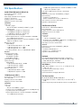
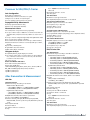
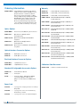
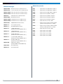
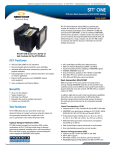
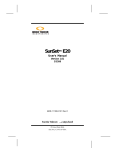
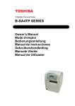
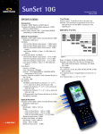
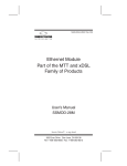
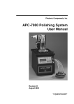
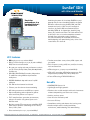
SunSet SDH
®
with Jitter and Wander
Benchtop
performance in a
handheld test set the SunSet SDH
Combining the power of a benchtop SDH/PDH set and
protocol analyzer into a handheld platform, the SunSet
SDH offers advanced testing for SDH, PDH, and ATM
networks and services. With electrical and optical
interfaces, the SunSet SDH tests from 64 kbit/s to
622 Mbit/s (STM-4). Its lightweight, durability, long
battery life, and low cost make it the ideal tool for field
technicians in the access and metropolitan networks.
And with jitter and wander testing capabilities,
save time and money for installation, maintenance,
troubleshooting, and commissioning tasks, either at the
central office or in the field.
KEY features
•
• SDH testing at 52, 155, and 622 Mbit/s
• PDH & T-Carrier testing at 1.5, 2, 34, 45, and 139 Mbit/s;
PDH/T-Carrier structured mode
• Bit error rate testing and error performance analysis
per ITU-T G.821, G.826, G.828, G.829, M.2100, M.2101,
and M.2110
• SDH-SDH, SDH-PDH MuxTest modes; Independent
Tx and Rx for testing ADMs and synchronous
multiplexers
• Tandem connections: errors, alarms, APId capture and
generation
• Voice frequency testing: talk/listen, send/receive tones,
noise measurements
• ATM testing at 1.5, 2, 34, 45, 155, and 622 Mbit/s
• ATM traffic generation, ATM QoS measurements, ATM
Adaptation Layer (AAL0, AAL1, AAL2, AAL5) tests
• IP over ATM testing, ATM DSL DSLAM test
• SDH/PDH MuxMode: drop and insert of 1.5/2M
tributaries
Benefits
• Full SDH overhead control and decode
• SDH/PDH/ATM feature-rich
• Tributary scan for alarm and error monitoring
• Lightweight and highly portable
• APS timing measurement and APS bytes capture
• Eliminates the need for multiple and heavier instruments
without compromising test features or accuracy
• Pointer monitoring, pointer adjustment, pointer
offset and G.783 pointer test sequences
• ITU-T compliant Jitter generation, measurement,
tolerance & transfer tests, pointer jitter test in
MuxTest mode
• Real time wander TIE measurements and offline MTIE/
TDEV analysis software conforming to ITU-T G.811,
G.812, G.813, G.823
• Intuitive and easy-to-use
• Cost-effective and future-proof
• Increases efficiency
• Consolidates training and shortens the learning curve
• Handles multiple tasks including installation,
maintenance, troubleshooting, and commissioning
• Pulse mask analysis at 1.5, 2, 34, and 45 Mbit/s
Supplied and supported in the UK by Phoenix Datacom - tel: 01296 397711 - [email protected] - www.phoenixdatacom.com
www.sunrisetelecom.com
Applications
Installation, Maintenance, Troubleshooting &
Commissioning
The SunSet SDH is the ideal product for installation and bringing
into service tasks in the field and central office. Commissioning and acceptance tests can be performed with the same test
set, as jitter and wander features are part of the conformance
procedures. Maintenance and troubleshooting in-service tasks
can also be completed with the same handheld test set saving
time and money.
Out-of-Service testing
ADM
Tx
Tx
ADM
STM-16
Optical Ring
Rx
ADM
Rx
ADM
Round trip delay
SDH/PDH
interface
NE
Network
NE
Out-of-Service Testing
• End-to-end BERT
Jitter generation/measurement
Jitter Generation
• Bringing into Service per ITU-T M.2110
Tx
Rx
• ATM testing
NE
Rx
• Trace generation
Tx
Jitter Measurement
• Round trip delay
• NE verification
Jitter tolerance/transfer measurements
• Pulse mask analysis at 1.5M, 2M, 34M, and 45M
Jitter
• Voice frequency testing: Talk/listen, send/receive tones
Error
NE
• MuxTest
• Jitter tests
MuxTest, Pointer jitter tests
– Jitter generation and measurement
High rate side
Low rate side
– Jitter tolerance and transfer measurement
– Pointer/mapping jitter test
• Wander tests
Rx
Tx
Tx
Rx
In-Service Monitoring
• Through protected monitoring points or optical splitters
Wander testing
• Line through and payload through mode
Tx
Rx
L1-Rx
Tx
NE
• Error performance analysis per G.826, G.828, G.829,
M.2101
L2-Rx
External
Clock
• SDH overhead bytes decode
• Pointer monitoring
• APS timing measurement and APS capture
• In-service tributary scan
• Voice traffic monitoring
In-Service monitoring
ADM
STM-16
Optical Ring
ADM
Through mode
2
SunSet SDH
Rx
ADM
• In-service jitter/wander measurements
• Troubleshooting synchronization problems
Wander Measurement
Primary Reference
Clock/Signal
ADM
SDH Specifications
622M/155M/52M Optical (STM-4/1/0)
Port/Connector: FCUPC or SCUPC
Line coding: NRZ
Mode: Single and multi-mode compatible
Complies to ITU-T G.957
Framing: Conforms to ITU-T G.707
Mapping: Conforms to ITU-T G.707
Transmitter
Clock source
Internal: ± 4 ppm
– Bit rates 622 Mbit/s, 155 Mbit/s, 52 Mbit/s: ± 4 ppm
Frequency offset
– 622.080 Mbit/s ± 50 ppm in 1, 10 ppm steps
– 155.520 Mbit/s ± 50 ppm in 1, 10 ppm steps
– 51.840 Mbit/s ± 50 ppm in 1, 10 ppm steps
Loop: Recovered from received signal
External: Synchronization to external 1.544 MHz or 2.048 MHz via 1.5/2M External Clock input
1.5/2M-L2-Rx: Synchronization to external 1.544 Mbit/s or 2.048
Mbit/s via 1.5/2M Line 2 input
Output power range
155/622 Mbit/s
– 1310 nm Intermediate Reach: -8 to -15 dBm
– 1310 nm Long Reach: +2 to -3 dBm
– 1550 nm Long Reach: +2 to -3 dBm
Laser Safety: IEC825-1, Class 1, 21 CFR 1040.10 & 1040.11
Receiver
Frequency recovery range
622.080 Mbps ± 50 ppm
155.520 Mbps ± 50 ppm
51.840 Mbps ± 50 ppm
Wavelength: 1280 -1580 nm
Input power range
155/622 Mbit/s
– 1310 nm Intermediate Reach: -30 dBm
– 1310 nm Long Reach: -30 dBm
– 1550 nm Long Reach: -30 dBm
Maximum input power
– 1310 Intermediate Reach: +3 dBm
– 1310/1550 nm Long Reach: -5 dBm
155M Electrical (STM-1)
Port/Connector: 75Ω unbalanced BNC (f)
Line coding: CMI
Framing: Conforms to ITU-T G.707
Mapping: Conforms to ITU-T G.707
Transmitter
1.5/2M-L2-Rx: Synchronization to external 1.544 Mbit/s or 2.048
Mbit/s via 1.5/2M Line 2 input
Pulse shape: 155M electrical conforms to ITU-T G.703
Receiver
Frequency recovery range: 155.520 Mbit/s ± 150 ppm
Input sensitivity
Terminate: 12.7 dB cable loss
Monitor: 20 dB resistive loss plus 12 dB cable loss
Jitter tolerance: Conforms to ITU-T G.825
Impedance: 75Ω unbalanced
52M Electrical (STM-0)
Port/Connector: 75Ω unbalanced BNC (f)
Line coding: B3ZS
Framing: Conforms to ITU-T G.707 Annex A
Mapping: Conforms to ITU-T G.707
Transmitter
Clock Source
Internal
− Bit rate: 51.840 Mbit/s ± 5 ppm
Frequency offset: 51.840 Mbit/s ± 500 ppm in 1, 10, 100 ppm steps
Loop: Recovered from received signal
Pulse shape: Conforms to ITU-R F.750-3
Receiver
Frequency recovery range: 51.840 Mbit/s ± 500 ppm
Input sensitivity
Terminate: 10.8 dB cable loss
Monitor: +3 to -26 dB resistive loss
Impedance: 75Ω unbalanced (f)
Payloads
ITU-T and ETSI mapping: Manual and graphic configuration
VC4-4c Bulk, VC4 Bulk, VC3 Bulk, VC12 Bulk, VC11 Bulk, 139M,
45M, 34M, 2M Async, 1.5M Async
Framed, Unframed, Structured PDH payloads
Test Patterns
STM-4, STM-1, STM-0: 223-1, 220-1, 215-1, 211-1, All 0s, All 1s, Alt
1010, 1-8, 1-16
User: 10 user patterns defined up to 16 bits
Test pattern inversion
Unselected channels: Unequipped, Broadcast
SDH Error Injection
Bit, B1, B2, B3, MS-REI, HP-REI, LP-REI, BIP-2
Programmable error burst 1 to 9999 count, or error rate 2x10⁻³ to
1x10⁻⁹
FAS error injection in periodic mode (burst of M errors every N frames)
Clock source
Internal
− Bit rate: 155.520 Mbit/s ± 4 ppm
Frequency offset: 155.520 Mbit/s ± 50 ppm in 1, 10, 100 ppm steps
Loop: Recovered from received signal
External: Synchronization to external 1.544 MHz or 2.048 MHz via 1.5/2M External Clock input
www.sunrisetelecom.com
3
SDH Alarm Generation
SDH-PDH Mux/Demux Testing
LOS, LOF, MS-AIS, MS-RDI, AU-AIS, AU-LOP, HP-RDI, HP-UNEQ,
TU-AIS, TU-LOM, LP-UNEQ, TU-LOP, HP-PLM, LP-PLM, LP-RFI,
LP-RDI, RS-TIM, HP-TIM, LP-TIM
Enhanced RDI [HP/LP-SRDI (Server), HP/LP-CRDI (Connectivity), HP/
LP-PRDI (Payload)]
Alarm generation in continuous or repetitive mode (burst of M
frames out of N frames)
Using two sets of physical ports: 2 Tx/2 Rx
The following combinations are applicable:
SDH Measurements (622M, 155M, 52M)
Errors: Bit, B1, B2, B3, BIP-2, MS REI, HP REI, LP REI
Alarms: LOS, LOF, OOF, MS-AIS, MS-RDI, AU-AIS, AU-LOP, HP-RDI,
HP-UNEQ, TU- AIS, TU-LOM, LP-UNEQ, TU-LOP, HP-TIM, LP-TIM,
HP-PLM, LP-PLM, LP-RFI, LP-RDI, Enhanced RDI [HP/LP-SRDI
(Server), HP/LP-CRDI (Connectivity), HP/LP-PRDI (Payload)],
Extended PLM (LP-EPLM)
Performance: ITU-T G.821, G.826, G.828, G.829, M.2101/M.2110
Optical power level measurement
Accuracy: ± 1 dBm
Optical reception saturation indication
Frequency measurements (test interface and payload): Moving bar
graph of slip count, max frequency, min frequency, frequency
deviation in ppm, clock slips, max positive wander, max negative
wander
Automatic tributary scan: 80 characters/line report of alarms/errors
per tributary. In-service and out-of-service for 1.5M, VC11 Bulk,
2M, VC12 Bulk, 34M, 45M, 139M, VC3 Bulk, and VC4 Bulk inside
STM1/4/16 with full report.
SDH Overhead Features
Overhead monitor and decode
Text encoding of all applicable bytes (K1, K2, S1, C2, etc.)
Full SOH/POH Overhead bytes control in binary or HEX format
Programming K1, K2 APS signalling bytes per ITU-T G.783 & G.841
Trace generation
J0 Section trace/generation: 1 byte SAPI format or 16 bytes
E.164 ASCII + CRC-7
J1/J2 Path trace/generation: 16 bytes E.164 ASCII sequence +
CRC-7 or 64 bytes E.164 ASCII sequence
Through mode for J0, J1, J2 bytes
Stores up to 5 traces per byte with alphanumeric labels
Programmable expected trace data for J0, J1, and J2 bytes
Path overhead monitor and decode
Text encoding of all applicable bytes (K1, K2, S1, C2, etc.)
Programmable POH bytes
DCC BER testing through D1 to D3, D4 to D12 bytes
Orderwire: Talk/listen through E1, E2 bytes
Pointer monitor
AU (bytes H1 and H2), TU (bytes V1 and V2)
Display number of pointer operations with respect to time
− Instantaneous pointer value display
− Graphical display of pointer movements with histogram
format
Pointer adjustment
Programming of pointer value, NDF, and SS bits
Increase and decrease the pointer value
SONET mode: Setting SS bits to generate/detect SONET signal
Pointer offset: Line or payload offset in ± 1, 10 ppm steps
4
SunSet SDH
• 622M 0/139M
• 155M 0/139M
• 622M 0/45M
• 155M E (0)/45M
• 622M 0/34M
• 155M E (0)/34M
• 622M 0/2M
• 155M E (0)/2M
• 622M 0/1.5M
• 155M E (0)/1.5M
MuxTest: The test pattern is generated on the low or high speed
port and the BERT is measured on the opposite port
MuxMode: Emulation of a mux for 1.5M/2M payloads only
SDH-SDH Mux/Demux Testing (SWSDHJ-116)
The following combinations are applicable:
• 622M 0/155M E (0)
• 155M E (0)/52M E
• 622M 0/52M E
• 155M E (0)/45M
Through Mode
Line through
Payload through
All SOH bytes can be modified except for B1, B2, H1, H2 bytes
Alarms/error insertion: LOS, LOF, MS-AIS, MS-RDI, B1, B2, MS-REI
Pointer Test Sequences
Specification: ITU-T G.783
AU or TU pointer
Sequences: Single, burst, phase, transient burst, periodic, 87-3, 261, opposite (increase + decrease), and custom
Movement: Increase, decrease, increase + decrease
Anomalies: Added, cancel, and none
Tandem Connections Monitoring
N1 byte for High Order Paths (VC-3/VC-4)
N2 byte for Low Order Paths (VC-11/VC-12)
Analysis of data, display of data in the form of alarms, performance
figures, and APId messages as specified in ITU-T G.707
Generation and detection of the following parameters:
Loss of Tandem Connection (LTC)
Loss of Multiframe (LOM)
Incoming Error Count (IEC)
Tandem Connection Remote Error Indication (TC-REI)
Tandem Connection Alarm Indication Signal (TC-AIS)
Tandem Connection Remote Defect Indication (TC-RDI)
Tandem Connection Outgoing Defect Indication (TC-ODI)
Tandem Connection Outgoing Error Indication (TC-OEI)
Tandem Connection UnEquipped (TC-UNEQ)
Tandem Connection Errors Difference (TC-DIFF)
Graphical display
Automatic Protection Switch Time Measurement
Measures time that anomaly is present
Resolution: 1 ms
Anomaly selection: MS-AIS, B2 errors, B3 error, AU-AIS, TU-AIS, LOS
Selectable switch time to display PASS or FAIL
Selectable gate time to control the minimum interval for the circuit
to be anomaly time
APS timing at 2M interfaces: 2M-AIS, 2M-LOS
APS bytes capture
Capture and decode states of K1/K2 bytes
– Store hundreds of messages
– Ring and linear decoding
125 µs resolution
Optional trigger with wildcards
Timestamp in frames or ms
Duration in absolute or elapsed time
Save or print results
Load and decode past results
Service disruption (bulk payloads)
PDH/T-Carrier specifications
139M
Port/Connector: 75Ω unbalanced BNC (f)
Line coding: CMI
Transmitter
Clock source
Internal
− Bit rate: 139.264 Mbit/s ± 5 ppm
Frequency offset (as test interface and as a payload): 139.264
Mbit/s ± 150 ppm in 1, 10, 100 ppm steps
Loop: Recovered from received signal
Pulse shape: Conforms to ITU-T G.703
Framing: Unframed, framed, structured per ITU-T G.751
Receiver
Frequency recovery range: 139.264 Mbit/s ± 150 ppm Input sensitivity
Terminate: 12 dB cable loss
Monitor: 20 dB resistive loss plus 12 dB cable loss
Jitter tolerance: Conforms to ITU-T G.823
Impedance: 75Ω unbalanced
45M
Port/Connector: 75Ω unbalanced BNC (f)
Line coding: B3ZS
Transmitter
Clock source
Internal
− Bit rate: 44.736 Mbit/s ± 5 ppm
Frequency offset (as test interface and as a payload): 44.736
Mbit/s ± 500 ppm in 1, 10, 100 ppm steps
Loop: Recovered from received signal
Pulse shape: Conforms to ITU-T G.703
Framing: Unframed, M13, and C-bit
Receiver
Frequency recovery range: 44.736 Mbit/s ± 500 ppm
Input sensitivity
Terminate: Up to -6 dB cable loss
Monitor: +6 dB to -26 dB resistive loss
Jitter tolerance: Conforms to ITU-T G.824
Impedance: 75Ω unbalanced
34M
Port/Connector: 75Ω unbalanced BNC (f)
Line coding: HDB3
Transmitter
Clock source
Internal
− Bit rate: 34.368 Mbit/s ± 5 ppm
Frequency offset (as test interface and as a payload): 34.368
Mbit/s ± 500 ppm in 1, 10, 100 ppm steps
Loop: Recovered from received signal
Pulse shape: Conforms to ITU-T G.703
Framing: Framed, unframed, structured per ITU-T G.751
Receiver
Frequency recovery range: 34.368 Mbit/s ± 500 ppm
Input sensitivity
Terminate: -12 dB cable loss
Monitor: -20 dB resistive loss plus -12 dB cable loss
Jitter tolerance: Conforms to ITU-T G.823
Impedance: 75Ω unbalanced
Dual 2M
Port/Connector
120Ω balanced RJ-45 (f) (SSSDHJ-RJ45)
120Ω balanced bantam (SSSDHJ-BTM)
Line coding: AMI, HDB3
Transmitters (Lines 1 and 2)
Clock source
Internal
− Bit rate: 2.048 Mbit/s ± 5 ppm
Frequency offset (as test interface and as a payload): 2.048 Mbit/s
± 5000 ppm in 1, 10, 100, 1000 ppm steps
External clock input port: 2.048 MHz
Recovered from Line 2 input (2.048 Mbit/s)
Loop: Recovered from received signal
Pulse shape: Conforms to ITU-T G.703 for balanced (120Ω) interfaces
Framing: Unframed, PCM-30/30C, PCM-31/31C conforms to ITU-T G.704
Fractional E1
Error measurements, channel configuration verification
Nx64 kbit/s (consecutive) or Mx64 kbit/s (nonconsecutive), N/M=1 to 30 or 1 to 31
Set Tx and Rx channels independently
Through mode: Test pattern on selected channels; all others through
Receivers (Lines 1 and 2)
Frequency recovery range: 2.048 Mbit/s ± 5000 ppm
Input sensitivity
Terminate, Bridge: +6 to -43 dB with ALBO
Monitor: -20 dB resistive loss plus -6 dB cable loss
Jitter tolerance: Conforms to ITU-T G.823
Impedance
Terminate, Monitor: 120Ω balanced
Bridge: > 1200Ω
Dual 1.5M
Port/Connector
100Ω balanced RJ-45 (f) (SSSDHJ-RJ45)
100Ω balanced bantam (SSSDHJ-BTM)
Line coding: AMI, B8ZS
Transmitters (Lines 1 and 2)
www.sunrisetelecom.com
5
Clock source
Internal
− Bit rate: 1.544 Mbit/s ± 5 ppm
Frequency offset (as test interface and as a payload): 1.544 Mbit/s
± 500 ppm in 1, 10, 100 ppm steps
External clock input port: 1.544 MHz
Recovered from Line 2 input (1.544 Mbit/s)
Loop: Recovered from received signal
Pulse shape: Conforms to ITU-T G.703
Framing: Unframed, SF-D4, ESF. Conforms to ANSI T1.102, 107, 107A,
403, and 404. Also Telcordia TR-TSY-000009 and TR-TSY-000191.
Fractional T1
Error measurements, channel configuration verification
Nx64 kbit/s or Nx56 kbit/s (consecutive or nonconsecutive), N=1 to 24
Set Tx and Rx channels independently
Through mode: Test pattern on selected channels; all others through
Receivers (Lines 1 and 2)
Frequency recovery range: 1.544 Mbit/s ± 500 ppm
Input sensitivity
Terminate, Bridge: +6 to -36 dB cable loss
Monitor: -15 to -25 dB, resistive loss
Jitter tolerance: Conforms to ITU-T G.824
Impedance
Terminate, Monitor mode: 100Ω balanced
Bridge: > 1000Ω
Test Patterns
223-1, 220-1, 215-1, 211-1, 29-1, 27-1, 26-1, All 0s, All 1s, Alt 1010,
20ITU, QRS, 1-8, 1-16, 3-24
User: 10 user patterns defined up to 32 bits
Test pattern inversion
PDH/T-Carrier Error Injection
139M, 34M: Code, Bit, FAS
45M: Code, Bit, Frame, C-bit, P-bit, FEBE
2M: Code, Bit, CRC-4, E-bit, FAS
1.5M: BPV, Logic, CRC-6, Frame
Programmable error burst 1 to 9999 count or error rate 2 x 10⁻³ to
1 x 10⁻⁹
PDH/T-Carrier Alarm Generation
139M, 34M: AIS, FAS RAI
45M, 1.5M: AIS, Yellow, Idle
2M: AIS, FAS RAI, MFAS RAI
PDH/T-Carrier Measurements (139M, 45M, 34M, 2M, 1.5M)
Error type Code, bit, FASE (2M, 8M, 34M, 139M)
CRC-4, E-bit (2M)
Code (BPV), F-bit, P-bit, C-bit, FEBE, CRC-6 (1.5M, 45M) Typical error type reports: Total error count, error rate, ES, %ES,
SES, %SES, UAS, %UAS, EFS, %EFS, AS, %AS
ITU-T G.821 analysis
ITU-T G.826 analysis: Based on anomalies, defects, far end indications
M.2100 analysis (Maintenance or BIS)
Alarm statistics
Loss of signal seconds, Loss of Frame seconds, AIS seconds
FAS RAI seconds (2M, 34M, 139M)
MFAS RAI seconds (2M only)
Yellow alarm seconds (1.5M, 45M)
6
SunSet SDH
Low density seconds, excess 0s seconds (1.5M)
Frequency measurements: Moving bar graph of slip count, max frequency, min frequency, frequency deviation in ppm, clock slips,
max positive wander, max negative wander
Signal level measurement (1.5/2M/34M/45M)
PDH Mux/Demux Testing
Using two sets of physical ports: 2 Tx/2 Rx
The following combinations are applicable:
• 139M/34M
• 45M/2M
• 139M/2M
• 45M/1.5M
• 34M/2M
MuxTest: The test pattern is generated on the low or high speed
port and the BERT is measured on the opposite port
Voice Frequency Testing (SWSDHJ-114)
Monitor speaker with volume control
Built-in microphone/speaker
Companding: A-law, µ law
Programmable idle channel A, B (C, D) bits (1.5M)
ABCD bits transmit and monitor in selected channel (2M)
VF level measurement: +3 to -60 dBm, resolution 0.1 dBm
VF frequency measurement: 50 to 3950 Hz, resolution 1 Hz
VF tone generation
Variable tone: 50 to 3950 Hz @ 1 Hz step. +3 to -60 dBm @ 1 dBm
Peak code and coder offset measurements
Noise measurements
Receiver filters
2M: 3.1 kHz, Psophometric, 1010 Hz notch
1.5M: 3 kHz flat, C-message, C-notch
Pulse Mask Analysis (SWSDHJ-190)
1.5M, 2M, 34M, and 45M pulse mask
Scan period: 500 ns
On screen pulse shape display with G.703 Pulse Mask verification
Displays pulse width, rise time, and fall time in ns, % overshoot, % undershoot
1.5M masks: ANSI T1.102, T1.403, AT&T TR 62411, G.703
45M masks: ANSI T1.404, G.703
Common To SDH/PDH/T-Carrier
Auto Configuration
Single button configuration
Automatically scans all test interfaces for signal
Configures test set based on received signal
Sets rate, mapping, payload, and/or test pattern
Propagation Delay Measurement
Round trip signal transmission delay
Measures in µs and UI (Unit Intervals)
Measurement Criteria
Test results/events storage and events log capability
Stores up to 20 test results or 800 errors or alarms events with user
definable labels; lock/unlock records, available to screen view or
print
Stores up to 10 user configurations (profiles) with alphanumeric labels
Print on event can be enabled or disabled
Print at timed interval (settable from 2 min up to 999 hr 59 min)
Measurement duration continuous or timed (settable up to 999 hr,
59 min)
Elapsed time, remaining time
Programmable start date and time
Audible alarm: On/off switchable
Histogram Analysis
Errors/Alarms/Pointer graphic display in real-time
Stores current results with 1-second resolution for the last 60 minutes, 1-minute resolution for the last 72 hours, and 15-minute
resolution for the last 57 days
CSV format storage
Status and Alarm Indicators
Power and low battery LED indicators
Pattern Sync and Bit Error
139M and STM-N (signal), Alarm, Frame, Errors, Pointer, ATM cell
8M, 34M and 45M (signal), Alarm, Frame, and Errors
1.5/2M-L2, Alarm, Errors
1.5/2M-L1, Alarm, Errors
Jitter Generation & Measurement
SDH Jitter
Jitter Measurement
Measurement range: According to ITU-T 0.172
Wideband Jitter Measurement
– 155.520 Mbit/s (500 Hz to 1.3 MHz) (SWSDHJ-155MJIT)
– 622.080 Mbit/s (1 kHz to 5 MHz) (SWSDHJ-622MJIT)
Highband Jitter Measurement
– 155.520 Mbit/s (65 kHz to 1.3 MHz) (SWSDHJ-155MJIT)
– 622.080 Mbit/s (250 kHz to 5 MHz) (SWSDHJ-622MJIT)
PASS/FAIL threshold: Per ITU-T G.825 or user defined
Test rates: 155.520 Mbit/s, 622.080 Mbit/s
Parameters: Current peak-peak, Maximum peak-peak, RMS,
Maximum RMS, Current +peak and –peak, Maximum +peak and
–peak,
Units: UI (Unit Interval)
Resolution: 0.01 UI
Test duration: Timed or continuous
Storage
Up to 100,000 measurement intervals
20 records
Measurement interval: 1 second
Jitter histogram
Jitter Generation
Modulation source type: Sinusoidal
Jitter amplitude/frequency: Conforms to ITU-T O.172
Jitter Tolerance Measurement
PASS/FAIL template: Conforms to ITU-T G.825
Test frequencies: Up to 30 points
Technique: Onset of errors
Storage: Up to 20 records
Fast Jitter Tolerance Measurement
PASS/FAIL template: Set to ITU-T G.825 by default
User programmable template (frequency points & amplitude values)
Technique: Onset of errors
Storage: Up to 20 records
Jitter Transfer Measurement
PASS/FAIL template: Conforms to ITU-T G.825
155.520 Mbit/s (500 Hz to 1.3 MHz)
622.080 Mbit/s (1 kHz to 5 MHz)
Test frequencies: Up to 30 points
Storage: Up to 20 records
PDH/T-Carrier Jitter
Jitter Measurement
Measurement range: According to ITU-T O.171 and O.172
Wideband Jitter Measurement
– 1.544 Mbit/s (10 Hz to 40 kHz) (SWSDHJ-DSnJIT)
– 2.048 Mbit/s (20 Hz to 100 kHz) (SWSDHJ-PDHJIT)
– 34.368 Mbit/s (100 Hz to 800 kHz) (SWSDHJ-PDHJIT)
– 44.736 Mbit/s (10 Hz to 400 kHz) (SWSDHJ-DSnJIT)
– 139.264 Mbit/s (200 Hz to 3.5 MHz) (SWSDHJ-PDHJIT)
Highband Jitter Measurement
– 1.544 Mbit/s (8 kHz to 40 kHz) (SWSDHJ-DSnJIT)
– 2.048 Mbit/s (18 kHz to 100 kHz) (SWSDHJ-PDHJIT)
– 34.368 Mbit/s (10 kHz to 800 kHz) (SWSDHJ-PDHJIT)
– 44.736 Mbit/s (30 kHz to 400 kHz) (SWSDHJ-DSnJIT)
– 139.264 Mbit/s (10 kHz to 3.5 MHz) (SWSDHJ-PDHJIT)
PASS/FAIL threshold: Per ITU-T G.823, G.824 or user defined
Test rates
2.048, 34.368, 139.264 Mbit/s
1.544 Mbit/s, 44.736 Mbit/s
Parameters: Current peak-peak, Maximum peak-peak, RMS,
Maximum RMS, Current +peak and –peak, Maximum +peak and
–peak
Units: UI (Unit Interval)
Resolution: 0.01 UIp-p
Accuracy: Per ITU-T O.171 and O.172
Test duration: Timed or continuous
Storage
Up to 100,000 measurement intervals
20 records
Measurement interval: 1 second
Jitter histogram
Jitter Generation
Modulation source type: Sinusoidal
Jitter amplitude/frequency: Conforms to ITU-T O.171
www.sunrisetelecom.com
7
Jitter Tolerance Measurement
PASS/FAIL template: Per ITU-T G.823, G.824
Test frequencies: Up to 30 points
Technique: Onset of errors
Storage: Up to 20 records
Fast Jitter Tolerance Measurement
PASS/FAIL template
Set to ITU-T G.823 (for 2M, 34M, 139M)
Set to ITU-T G.824 (for 1.5M, 45M)
User programmable template (frequency points & amplitude values)
Technique: Onset of errors
Storage: Up to 20 records
Jitter Transfer Measurement
PASS/FAIL template: Per ITU-T G.735, G.736 ,G.737, G.742, G.751, G.752
1.544 Mbit/s (from 10 Hz to 40 kHz)
2.048 Mbit/s (10 Hz to 100 kHz)
34.368 Mbit/s (100 Hz to 800 kHz)
44.736 Mbit/s (10 Hz to 400 kHz)
Test frequencies: Up to 30 points
Storage: Up to 20 records
Pointer Jitter Test
SDH-PDH MuxTest mode with Pointer Test Sequences generation on
Tx side, and Jitter measurements on the Rx side
Wander Generation & Measurement
SDH/PDH Wander Measurement
Measurement range: According to ITU-T O.171 and ITU-T O.172
Test interface
2.048 Mbit/s (SWSDHJ-TIE)
1.544*, 34.368, 44.736, and 139.264 Mbit/s (SWSDHJ-PDHTIE)
155.020 Mbit/s (SWSDHJ-155MTIE)
622.080 Mbits/s (SWSDHJ-622MTIE)
Reference clock: 1.544, 2.048, 5, 10 MHz, 1.544/2.048 Mbit/s (L2-Rx)
Parameters
Real Time Measurements
Time Interval Error (TIE)
– Amplitude (ns)
– Maximum and minimum TIE value
Off-line measurements (SWSDHJ-WAN)
– Maximum Time Interval Error (MTIE)
– Time Deviation (TDEV)
– Graphic display of results according to G.810, G.811, G.812,
G.813, and G.823 MTIE/TDEV masks
– TIE data transfer from test set to PC via 10Base-T port
Wander Generation
Modulation source type: Sinusoidal
Wander amplitude/frequency: According to ITU-T O.172
Test interface
2.048 Mbit/s (SWSDHJ-TIE)
155.020 Mbit/s (SWSDHJ-155MTIE)
622.080 Mbit/s (SWSDHJ-622MTIE)
Reference clock: 2.048 MHz
*Note: 1.544 Mbit/s TIE measurement accuracy does not fully meet ITU-T 0.171 nd 0.172
8
SunSet SDH
ATM Testing
Mapping
1.5/2M: PLCP and HEC-based per ITU-T G.804 and also nonG.804 compliant
34M: PLCP and HEC-based per ITU-T G.804 with framing based
on ITU-T G.832
45M: PLCP and HEC-based per ITU-T G.804
SDH: HEC-based per ITU-T G.707 (mapping using VC4 and VC12)
Interface: UNI and NNI per ITU-T I.361
Header control: GFC, VPI/VCI, PTI, CLP
Scrambling: On or off
Idle cells: Idle or null
C2 POH Hex: 13 (default)
Pattern truncate
Display: VPI/VCI in decimal or hexadecimal
ATM cell LED indicates presence of valid ATM cells
OAM cell generation
VCC scan: 128 independent headers
AAL 0/1/2/5 generation and analysis
Quality of Service
Timed or continuous measurement
Programmable start time and date
Traffic Supervision
8 independent VCC filters: 1 foreground, 7 background
Foreground: Full QoS, BERT, OAM counter, and statistics
Background: Traffic statistics and OAM monitoring only
Quality of Service: Errored cells and CER, lost cells and CLR, misinserted cells and CMR, SECB and SECB rate
ATM alarms: VP-/VC-LOC, AIS, RDI, LFMF (segment, end-to-end)
Global measurements: Total cells, idle cells, HEC errors (correctable
and non-correctable), HEC rate
Delay measurements: Cell Transit Delay (CTD) (MEAN, MIN, and MAX)
and Cell Delay Variation (CDV) Peak to Peak 2-point (MAX, MIN)
– Requires timestamp field or O.191 test cell
Total, congested, tagged count and rate Cps (cells per second)
Bit errors and bit error rate, CRC errors
OAM cell count: F4/F5, segment/end-to-end, AIS/RDI/loopback
OAM count: Continuity check, Performance management
Graphical display in histogram format of bit errors, CHEC, NCHEC,
cell loss seconds, cell errors and OAM cell count (F4/F5, segment/
end-to-end, AIS/RDI, loopback) ATM View Test Records
Stores up to 20 ATM test results with user definable labels
Lock/unlock records, available to screen view or print
Transferable to PC in CSV format by using Windows Remote Control VCC Scan
Up to 128 independent headers: GFC, VPI, VCI, PTI, CLP, AAL type
AAL scan
Save up to 8 VCC configurations
Utilization %
Cell Capture & Decode
Cell type capture selection: User, OAM, USER + OAM
Full buffer option to cycle or stop
Timed or continuous capture
Programmable start time and date
Display cell header and payload of 4096 cells
Header decode: GFC, VPI/VCI, PTI, CLP
OAM decode per ITU-T I.610
Fault management
AIS/RDI: Defect type, defect location
Loopback: Loopback ID, correlation tag, loopback location ID,
source ID
Performance management
Forward and backward
MCSN, BEDC, BLER, TUC (0+1), TUC (0), TRCC (0+1), TRCC (0),
timestamp
Activation/deactivation: Message, direction, correlation tag, PM
block size A-B & B-A
System management
Cell storage
Save up to 10 cell capture screens
Print
DSLAM Testing
Traffic Generation
Protocols
RFC 1483: LCC-Bridge (static & dynamic [DHCP]) & LCC-Route
RFC 2364: PPP over ATM (PPPoA)
RFC 2516: PPP over Ethernet (PPPoE)
RFC 2225: Classical IP and ARP over ATM
InARP
− In ARP Request to Far End
− In ARP Request Sent, Received
− In ARP Response Received, Sent
− In ARP Response from
− In ARP Request from
Number of PINGs: Up to 65535
PING length: 1 to 1500 bytes
User selectable bit rate down to 1 kbit/s
Clear Pass/Fail indication
Statistics
PINGs sent, state, received, unreachable, missing
Round trip: Current, average, maximum, and minimum
PING response/echo: Time, IP addresses, total PINGs
8 independent VCCs: 1 foreground, 7 background
Foreground VCC
Traffic: Constant Bit Rate (CBR), Unspecified Bit Rate (UBR)
Burst, Variable Bit Rate (VBR), and Sequential Cells
Cell Type: User, O.191 Test Cell, OAM-B Cell Performance
Patterns: 223-1, 220-1, 215-1, All 1s, All 0s, and 16-bit user patterns
Background VCCs
Traffic: CBR
Cell type: User
Patterns: 16-bit User patterns
AAL 0
Traffic: CBR, VBR/UBR, Sequential Cells
Patterns: 223-1, 220-1, 215-1, All 1s, All 0s, and 16-bit user patterns
PCR: %, Mbps, Cps
AAL 1
SRTS (Synchronous Residual Time Stamp): On, Off
Clock recovery adaptive method
PDH: 1.5M, 2M
Frame
− For 1.5M: Unframe, SF-D4, ESF
− For 2M: Unframe, PCM-30, PCM-30C, PCM-31, PCM-31C
Traffic
− Fixed at T1 (PCR: 1.741 Mbps [4106 Cps])
− Fixed at E1 (PCR: 2.309 Mbps [5446 Cps])
Patterns: 223-1, 220-1, 215-1, All 1s, All 0s, and 16-bit user patterns
AAL 2
Length
CID (Channel Identifier)
Traffic: CBR, VBR/UBR, Sequential Cells
Patterns: 223-1, 220-1, 215-1, All 1s, All 0s, and 16-bit user patterns
PCR: %, Mbps, Cps
AAL 5
CPCS-UU (Common Part Convergence Sublayer-User to User)
indication number
CPI (Common Part Indicator)
Frame rate: 0 - 50
Error injection: Bit, HEC, and NC-HEC errors, burst and rate
Alarm generation: F4/F5, segment/end-to-end, AIS, RDI, loopback,
continuity check
ATM end-to-end connectivity test between customer premises
(SSxDSL/MTT) and CO (SSSDH); back-to-back with SunSet xDSL/
MTT ATU-R Module
– SunSet xDSL/MTT requires software option SWxDSL-xxATM
– Auto detection of SSxDSL/MTT at far end
Bidirectional, asymmetric DSL throughput testing
Upstream and downstream statistics
Tx and Rx cell rates
Cell loss %
Bit error count, BER, and bit error injection
Clear Pass/Fail indication
Test results available on both units
ATM/IP PING Test
Product Description
Upgrades: SW options upgradeable via software in-field cartridge
replacement
Display: Backlit 320 x 240 pixels STN indoor/outdoor Color screen
with CFL Backlight
Printer: Report printing via serial port, RS-232 DIN-9
Network: 10Base-T DIN-9
Battery: Built-in NiMH rechargeable battery pack
Power: AC operation w/100 to 240 VAC, 50/60 Hz universal charger
Environmental
Operating temperature: 32 to 113°F (0 to 45°C)
Storage temperature: -4 to 158°F (-20 to 70°C)
Humidity: 5% to 90% noncondensing
Dimensions
Size: 4.3 x 2.8 x 10.6 in (11 x 7 x 27 cm)
Weight: 3.3 lb (1.5 kg)
www.sunrisetelecom.com
9
Ordering Information
Warranty
SSSDHC-STM16J ���SunSet SDHC Jitter and Wander, 2M, 34M and
155M test interfaces. RS232 and 10Base-T ports.
[Includes Certificate of Calibration, Windows
Remote Control, Histogram Analysis, 1.5 Mbps
Testing, 45 Mbps Testing, 139 Mbps Testing, PDH
MUX-DEMUX Testing, 52 Mbps Testing, G.783
Pointer Test Sequences, Tandem Connections
Monitoring, APS Switching Timing, SA295 and
1 year standard warranty. (Excludes Battery and
Accessories, which are warranty for one-year) ]
SSSDHC-W1 �����������SunSet SDHC-W1, Standard Warranty
Optics Options
STM1-13L15L-W1�������OPTICAL INTERFACE,STM-0/1 1310NM/1550NM
LR,STD WR
SSSDHJ-NONE �������Electrical only unit. (BNC) No optical Connectors
STM1-13L15L-EW1�����OPTICAL INTERFACE,STM-0/1 1310NM/1550NM
LR,1 YR EXTD WR
SSSTM1-13IR�����������Optical Interface, STM-0/1 1310 nm
Intermediate Reach
SSSTM1-13L/15L�����Optical Interface, STM-0/1 1310 nm/1550 nm
Long Reach
SSSDHC-EW1 ���������SunSet SDHC, 1 Yr Extended Warranty
SSSDHC-EW2 ���������SunSet SDHC, 2 Yr Extended Warranty
SSSTM1-13IR-W1���OPTICAL INTERFACE,STM-0/1 1310NM IR,
Standard Warranty
SSSTM1-13IR-EW1�����OPTICAL INTERFACE,STM-0/1 1310NM IR,1 Yr
Extended Warranty
SSSTM1-13IR-EW2�����OPTICAL INTERFACE,STM-0/1 1310NM IR,2 YRS
Extended Warranty
STM1-13L15L-EW2�����OPTICAL INTERFACE,STM-0/1 1310NM/1550NM
LR,2YRS EXTD WR
STM4-13IR-W1�����������OPTICAL INTERFACE,STM-0/1/4 1310NM IR,STD WR
SSSTM4-13IR�����������Optical Interface, STM-0/1/4 1310 nm
Intermediate Reach
STM4-13IR-EW1���������OPTICAL INTERFACE,STM-0/1/4 1310NM IR,1 YR
Extended Warranty
SSSTM4-13L/15L�����Optical Interface, STM-0/1/4 1310 nm/1550 nm Long Reach
STM4-13IR-EW2�����OPTICAL INTERFACE, STM-0/1/4 1310NM IR,2YRS
Extended Warranty
Optical Interface Connector Options
STM4-13L15L-W1�������OPTICAL INTERFAC,STM-0/1/4 1310NM/1550NM
Extended Warranty
SSSDHJ-FC �������������FCUPC Optical Connectors
STM4-13L15L-EW1�����OPTICAL INTERFAC,STM-0/1/4 1310NM/1550NM
LR,1 YR Extended Warranty
SSSDHJ-SC �������������SCUPC Optical Connectors
Electrical Interface Connector Options
STM4-13L15L-EW2�����OPTICAL INTERFAC,STM-0/1/4 1310NM/1550NM
LR,2YRS Extended Warranty
SSSDHJ-RJ45 ���������1.5/2M RJ-45 Connectors
SSSDHJ-BTM�����������1.5M/2M Bantam Connectors
Standard & Configurable Accessories Options
SSSDHC-101�����������SunSet SDH User’s Manual
SA904�����������������������Training CD
SS138E���������������������SunSet AC Adapter, 100-240 VAC, 50/60 Hz,
3-prong input, Output 15 VDC @ 3.3A
[Only for use with SunSets with NiMH battery
pack]
Power Cord
SA155-EU ���������������2-prong power cord plus ground for use in Europe
(Except UK)
SA155-NA���������������3-prong power cord for use in Latin America,
North America, and Asia
SA155-UK ���������������3-prong power cord for use in United Kingdom
10
SunSet SDH
Calibration Data Document
SSSDHC-CCM �������Calibration Test Measurement Data
Software Packages
Optical Accessories
SWSDHJ-PDHJIT�����PDH Jitter Generation and Measurement
SA501 ���������������������� Optical Patch Cord, SMF, FCUPC to FCUPC, 6’
SWSDHJ-DSnJIT�����T-Carrier Jitter Generation and Measurement
SA502 ���������������������� Optical Patch Cord, SMF, FCUPC to SCUPC, 6’
SWSDHJ-155MJIT���STM-1 Jitter Generation and Measurement
SA503 ���������������������Optical Patch Cord, SMF, FCUPC to STUPC, 6’
SWSDHJ-622MJIT���STM-4 Jitter Generation and Measurement
SA508 ���������������������Optical Patch Cord, LCUPC to SCUPC, 6’
SWSDHJ-TIE�������������2M TIE Generation and Measurement
SA509 ���������������������Optical Patch Cord, LCUPC to FCUPC, 6’
SWSDHJ-PDHTIE ���PDH TIE Measurements
SA511 ���������������������Optical Patch Cord, SCUPC to SCUPC, 6’
SWSDHJ-155MTIE �155M TIE Generation and Measurement
SA512 ���������������������Optical Patch Cord, SCUPC to STUPC, 6’
SWSDHJ-622MTIE �622M TIE Generation and Measurement
SA521 ���������������������Optical Attenuator, FC-PC, -10 dB
SWSDHJ-WAN �������MTIE/TDEV Wander Measurements
SA523 ���������������������Optical Connector Adapter, FCUPC to SCUPC
[Changes a FC (f) appearance to a SC (f)]
SWSDHJ-114 ���������Voice Frequency Testing
SA524 ���������������������Optical Connector Adapter, SCUPC to FCUPC
[Changes a SC (f) appearance to a FC (f)]
SWSDHJ-116�����������SDH-SDH Mux/Demux Testing
SWSDHJ-129 ���������1.5 Mbps ATM Testing
[Includes User’s Manual SSSDHC-101-3]
SWSDHJ-130 ���������2 Mbps ATM Testing
[Includes User’s Manual SSSDHC-101-3]
SWSDHJ-131 ���������45 Mbps ATM Testing
[Includes User’s Manual SSSDHC-101-3]
SA531 ���������������������Optical Attenuator, SC-PC, -10 dB
SA541 ���������������������Optical Splitter, FC-PC, 90/10
SA545 ���������������������Optical Splitter, FC-PC, 50/50
SA551 ���������������������Optical Splitter, SC-PC, 90/10
SA555 ���������������������Optical Splitter, SC-PC, 50/50
SWSDHJ-132 ���������34 and 155 Mbps ATM Testing
[Includes User’s Manual SSSDHC-101-3]
SWSDHJ-133 ���������622 Mbps ATM Testing
[Includes User’s Manual SSSDHC-101-3]
SWSDHJ-ATM���������ATM Software Package
[Includes SWSDH-130 and SWSDH-132]
SSSDHJ-ATM�����������VC12 ATM Testing
SWSDHJ-190�����������Pulse Mask Analysis
www.sunrisetelecom.com
11
Supplied and supported in the UK & Ireland by Phoenix Datacom
tel: 01296 397711 - [email protected] - www.phoenixdatacom.com
© 2011 Sunrise Telecom Incorporated. All rights reserved. Specifications subject to change without notice. All product and company names are trademarks of their respective corporations. Sunrise Telecom San Jose and Taiwan facilities are ISO 9001 certified. Do not reproduce, redistribute, or repost without written permission from Sunrise Telecom. SunSet® SDH Data sheet C0129, May 11, 2012