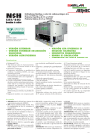
1
MANUALE DI ISTRUZIONI / INSTRUCTION MANUAL
CONDENSATORI AD ARIA / AIRCOOLED CONDENSER
CAL
CONDENSATORI AD ARIA / AIRCOOLED CONDENSER
Modelli Mono-circuito / Single circuit model
0251 - 0331 - 0361 - 0511
0661 - 0801 - 1011 - 1301
Modelli Bi-circuito / Dual circuit model
1802 - 2002 - 3002 - 4002 - 5002
MANUALE DI ISTRUZIONI / INSTRUCTION MANUAL
GB
© UNIFLAIR 2004
CAL - Rev 2.3 – 24-02-2004 IT - EN
1 (28)
MANUALE DI ISTRUZIONI / INSTRUCTION MANUAL
CONDENSATORI AD ARIA / AIRCOOLED CONDENSER
Alcune caratteristiche delle unità in versione speciale potrebbero
discostarsi da quelle descritte nel presente manuale.
The following general characteristics are relevant to standard units
designed according to the available options found on the units price
list.
UNIFLAIR ITALIA S.p.A.
Via dell’Industria, 10
35020 BRUGINE (Padova) Italy
Tel. +39 (0)49 9713211
Fax. +39 (0)49 5806906
Internet: www.UNIFLAIR.com
E-Mail: [email protected]
Release:
2.3
Date:
24 – 02 - 04
Checked by:
CAL - Rev 2.3 – 24.02.04 IT - EN
2 (28)
MANUALE DI ISTRUZIONI / INSTRUCTION MANUAL
CONDENSATORI AD ARIA / AIRCOOLED CONDENSER
Indice
Pagina
4
4
5
6
6
7
7
7
8
9
10
12
12
12
13
16
16
Simbologia
Norme di sicurezza
Descrizione generale
Descrizione e destinazione d’uso
Targa d'identificazione
Trasporto e movimentazione
Dimensioni e pesi
Installazione
Spazio operativo
Dimensioni delle connessioni frigorifere
Collegamenti frigoriferi
Collegamenti elettrici
Cavi d'alimentazione - protezioni
Avviamento
Organi di regolazione - taratura
Manutenzione
Ricerca guasti
Index
Symbols used
Safety Instructions
General Description
Description and use
Nameplate
Transport - Positioning On Site
Dimensions And Weight
Installation
Working Space
Size of refrigerant connections
Refrigerant Connections
Electrical Connections
Power Supply Cables - Protection
Start-Up
Control Devices - Adjustment
Maintenance
Fault Finding
CAL - Rev 2.3 – 24-02-2004 IT - EN
Page
17
17
18
19
19
20
20
20
21
22
23
25
25
25
26
29
29
3 (28)
MANUALE DI ISTRUZIONI / INSTRUCTION MANUAL
CONDENSATORI AD ARIA / AIRCOOLED CONDENSER
SIMBOLOGIA
SIMBOLO
SIGNIFICATO
PERICOLO GENERICO
SIMBOLO
SIGNIFICATO
ORGANI IN MOVIMENTO
AVVERTENZE IMPORTANTI
SUPERFICI
D'USTIONE
CALDE,
COMPONENTI
IN
TENSIONE,
PERICOLO ELETTRICO
SUFERFICI TAGLIENTI
PERICOLO
NORME DI SICUREZZA
•
•
•
•
•
•
•
•
•
Prima di qualsiasi intervento leggere attentamente il libretto d'istruzioni
Il condensatore è pressato in fabbrica con azoto o con aria secca per prevenire l’ingresso d'umidità. Prima di
rimuovere i tappi sugli attacchi in fase di installazione, scaricare l’azoto per mezzo della valvola a spillo sul
collettore d’entrata.
Il condensatore lavora in pressione: la manomissione dei raccordi o delle tubazioni può provocare fuoriuscite
di gas compresso
La tubazione d'ingresso al condensatore può assumere temperature superiori a 70°C e presenta quindi
pericolo d'ustione
INSTALLARE IL CONDENSATORE IN POSIZIONE INACCESSIBILE A PERSONE NON AUTORIZZATE: le
alette dello scambiatore di calore sono in lamiera d'alluminio di piccolo spessore e possono tagliare in caso
di contatto involontario.
Il condensatore è in tensione e contiene parti rotanti: prima di intervenire su qualsiasi parte elettrica
oppure sul ventilatore/i aprire il sezionatore (portare la manopola in posizione “O”)
Tutte le operazioni di servizio o manutenzione devono essere effettuate con macchina ferma e
devono essere condotte da personale esperto e qualificato.
In caso d'incendio l’acqua e le altre sostanze conduttrici non devono essere usate per lo spegnimento in
prossimità delle parti elettriche sotto tensione. Tale divieto dev’essere esposto nel luogo d'installazione della
macchina, mediante avvisi.
I refrigeranti impiegati, se direttamente a contatto con fiamme, si decompongono dando origine ad acidi o
altre sostanze irritanti. L’odore acre di tali sostanze, già a concentrazioni minori dei valori pericolosi, dà
un avvertimento tale da consentire l’evacuazione della zona a rischio.
Assicurarsi che la tensione d'alimentazione corrisponda a quella riportata nei valori di targa.
CAL - Rev 2.3 – 24.02.04 IT - EN
4 (28)
MANUALE DI ISTRUZIONI / INSTRUCTION MANUAL
CONDENSATORI AD ARIA / AIRCOOLED CONDENSER
DESCRIZIONE GENERALE
DISPOSIZIONE CON FLUSSO D’ARIA ORIZZONTALE
Fig. 1.a. - CAL 0251…1301
Fig. 1.b. - CAL 1802…5002
DISPOSIZIONE CON FLUSSO D’ARIA VERTICALE
Fig. 2.a. - CAL 0251…1301
1
2
3
4
5
6
7
N.B.:
Fig. 2.b. - CAL 1802…5002
Ventilatore
Staffe di supporto
Gambe di supporto
Connessioni frigorifere
Sezionatore
Regolatore di pressione
Targa d'identificazione
Il numero e la disposizione dei ventilatori varia con il modello di condensatore
CAL - Rev 2.3 – 24-02-2004 IT - EN
5 (28)
MANUALE DI ISTRUZIONI / INSTRUCTION MANUAL
CONDENSATORI AD ARIA / AIRCOOLED CONDENSER
DESCRIZIONE E DESTINAZIONE D’USO
Condensatori remoti con ventilatore assiale a basso numero di giri idonei ad installazione all’aperto,
completamente assemblati e collaudati in fabbrica. I condensatori possono essere installati sia in posizione
verticale (flusso aria orizzontale) oppure in posizione orizzontale (flusso aria verticale). Le unità sono dotate di
controllo della pressione di condensazione per ciascun circuito, nelle unità bicircuito è standard il controllo
modulante della velocità dei ventilatori con regolatore a taglio di fase: in questo caso è data priorità al circuito in
cui la pressione è maggiore.
Carrozzeria: i condensatori CAL sono realizzati con struttura autoportante in alluminio goffrato con elevatissima
resistenza alla corrosione.
Ventilatori: di tipo assiale bilanciati staticamente e dinamicamente su due piani, con pale di disegno innovativo
realizzate in alluminio pressofuso. Il motore elettrico è del tipo a rotore esterno, IP54 classe “F”, particolarmente
adatto alla regolazione di velocità con sistemi a taglio di fase. La griglia di sicurezza a protezione del ventilatore
è conforme alle vigenti norme di sicurezza.
Batteria condensante: ad ampia superficie frontale e disposta a monte dei ventilatori per un’ottimale
distribuzione dell’aria. É realizzata con tubi in rame espansi meccanicamente su alette d’alluminio.
Collegamenti frigoriferi: le connessioni sono di tipo ROTALOCK maschio disposte su un lato dell’unità per un
collegamento rapido e sicuro alle tubazioni provenienti dall’unità motoevaporante.
Impianto elettrico: interruttore sezionatore generale con grado di protezione IP44 per le unità monocircuito e
IP65 per la unità bicircuito disposto sul lato ventilatori dell’unità, regolatori di pressione precablati e (sulle unità
bicircuito) protetti da un’opportuna carenatura.
TARGA D'IDENTIFICAZIONE
La targhetta d'identificazione, applicata sul condensatore, riporta le seguenti indicazioni:
• Modello della macchina;
• Numero di matricola;
• Anno di costruzione;
• Corrente e potenza assorbite;
• Valori di taratura standard.
CAL - Rev 2.3 – 24.02.04 IT - EN
6 (28)
MANUALE DI ISTRUZIONI / INSTRUCTION MANUAL
CONDENSATORI AD ARIA / AIRCOOLED CONDENSER
TRASPORTO E MOVIMENTAZIONE
Il condensatore ha lasciato la fabbrica in perfetto stato; al momento della consegna; controllarne l’integrità e
notificare subito per iscritto al trasportatore ogni danno che possa essere attribuito ad un trasporto rude.
Durante il trasporto e il tiro in sito:
• non reclinare o capovolgere il condensatore.
• prima di rimuovere l’imballo, trasportare il condensatore nel punto più vicino al luogo d'installazione per
mezzo di un transpallet oppure di un carrello trasportatore stabile, assicurando l’unita’ per evitarne il
ribaltamento.
• rimuovere l’imballo prestando attenzione a non danneggiare l’unità.
La simbologia applicata sull’imballo è conforme alla norma ISO7000; il significato dei segni grafici è riportato in
tabella.
SEGNO GRAFICO SIGNIFICATO
FRAGILE:
manipolare
precauzione.
con
TEME L’UMIDITÁ: indica che
l’imballaggio dev’essere tenuto in
luogo asciutto.
CENTRO DI GRAVITÁ: indica il
centro di gravità dell’imballaggio di
spedizione.
TEME IL CALORE: indica che
l’imballaggio di spedizione deve
essere tenuto distante da fonti di
calore.
SEGNO GRAFICO SIGNIFICATO
ALTO: indica la posizione
corretta
dell’imballaggio
di
spedizione.
LIMITI DI TEMPERATURA:
indica i limiti di temperatura
entro i quali l’imballaggio
dev’essere
conservato
e
manipolato.
NON UTILIZZARE GANCI:
indica che sono proibiti i ganci
per
il
sollevamento
dell’imballaggio di spedizione.
NON
SOVRAPPORRE
gli
imballi.
DIMENSIONI E PESI
Vedi disegni allegati DIUI...
INSTALLAZIONE
Porre il condensatore all’aperto evitando l’esposizione all’insolazione diretta.
Esso può essere installato:
• con flusso d’aria orizzontale (versione standard) per una migliore protezione (dalla neve o da oggetti
provenienti dall’alto) e una più facile manutenzione; con quest'assetto il condensatore necessita di protezione
dal vento che potrebbe interferire con il funzionamento del ventilatore;
• con flusso d’aria verticale; quest'assetto è consigliato per l’installazione in zone ventose o laddove il flusso
d’aria orizzontale sia ostruito ed è realizzabile per mezzo del kit gambe opzionale (4 gambe per i modelli:
0251…0661 e 1802…4002; 6 gambe per i modelli: 0801…1301 e 5002). Per le operazioni di montaggio vedi
lo schema allegato al kit gambe.
Il peso contenuto dei condensatori CAL ne permette l’installazione su solette di portata modesta.
Poggiare il condensatore su una superficie solida e piana.
Se necessario livellare con spessori in modo che la pendenza non superi 1 grado.
Fissare il condensatore utilizzando gli appositi fori sulle staffe di base (flusso d’aria orizzontale) oppure sulle
estremità inferiori delle gambe (flusso d’aria verticale).
CAL - Rev 2.3 – 24-02-2004 IT - EN
7 (28)
MANUALE DI ISTRUZIONI / INSTRUCTION MANUAL
CONDENSATORI AD ARIA / AIRCOOLED CONDENSER
SPAZIO OPERATIVO
Rispettare le distanze minime indicate in fig. 3, necessarie per una libera circolazione dell’aria e per la
manutenzione dell’unità.
> 0,7 m
>4m
>1m
>4m
>1m
Fig. 3.a.: FLUSSO D’ARIA ORIZZONTALE
Fig. 3.b.: FLUSSO D’ARIA VERTICALE
INSTALLARE IL CONDENSATORE IN POSIZIONE INACCESSIBILE A PERSONE NON
AUTORIZZATE:
L’alettatura dello scambiatore di calore è in lamiera d'alluminio spessa 0,1 mm ed è
potenzialmente tagliente in caso di violento contatto involontario.
NB: la caratteristica dei ventilatori non consente la canalizzazione dell’aria.
CAL - Rev 2.3 – 24.02.04 IT - EN
8 (28)
MANUALE DI ISTRUZIONI / INSTRUCTION MANUAL
CONDENSATORI AD ARIA / AIRCOOLED CONDENSER
DIMENSIONI DELLE CONNESSIONI FRIGORIFERE
Il condensatore è provvisto di connessioni tipo
ROTALOCK maschio.
Fig. 4.a.
Gli attacchi rotalock diritti femmina forniti a
corredo dell’unità (fig. 4.b.) devono essere avvitati
sui rubinetti del gas e del liquido verificando che
siano presenti le guarnizioni bianche in teflon.
linea del liquido
1” maschio (0251…0361)
1 ¼" maschio (0511…5002)
Attacco rotalock femmina
per la linea del liquido
linea del gas
1” maschio (0251…0361)
1 ¼" maschio (0511…1802)
1 ¾" maschio (2002…5002)
Attacco rotalock femmina
per la linea del gas
ODS
ODS
ØINTERNO 12 mm
ØINTERNO 16 mm
(0251-0331)
(0251-0331-0361)
ØINTERNO 16 mm
ØINTERNO 18 mm
(0361-0511-0661)
(0511-0661)
ØINTERNO 18 mm
ØINTERNO 22 mm
(0801-1011-1301)
(0801-1011-1301)
ØINTERNO 22 mm
ØINTERNO 28 mm
(1802)
(1802)
ØINTERNO 28 mm
ØINTERNO 35 mm
(2002-3002-4002-5002)
(2002-3002-4002)
ØINTERNO 42 mm
Fig. 4.b.
(5002)
In alternativa agli attacchi femmina diritti possono
essere forniti a richiesta:
- giunti ad angolo (vedi fig. 5.a.);
- rubinetti d'intercettazione (vedi fig. 5.b.).
A
B
A: ATTACCO ROTALOCK MASCHIO
B: GUARNIZIONE
A
B
Fig. 5.a.
CAL - Rev 2.3 – 24-02-2004 IT - EN
Fig. 5.b.
9 (28)
MANUALE DI ISTRUZIONI / INSTRUCTION MANUAL
CONDENSATORI AD ARIA / AIRCOOLED CONDENSER
NOTA: Il diametro delle linee frigorifere tra
condizionatore e condensatore remoto (De)
dev'essere scelto in funzione della lunghezza delle
stesse, pertanto non sempre coinciderà con il
diametro interno (ODS) dell'attacco rotalock fornito
da UNIFLAIR.
De
Fig. 6.
COLLEGAMENTI FRIGORIFERI
Il condensatore è pressato in fabbrica con aria secca (modelli 0251…1301) o azoto (modelli
1802…5002) per prevenire l’ingresso d'umidità e chiuso con tappi.
PRIMA DI RIMUOVERE I TAPPI SUGLI ATTACCHI SCARICARE L’AZOTO PER MEZZO DELLA
VALVOLA A SPILLO SUL COLLETTORE D’ENTRATA.
A
A
A
A
D
E
B
B
E
1
2
C
3
4
Fig. 7.
1. Svitare il tappo giallo (E) avvitato sull’attacco rotalock (A);
2. Rimuovere la guarnizione nera in gomma (D): questa guarnizione è utilizzata solamente per garantire la
tenuta del circuito precaricato con azoto o aria secca;
3. Verificare che sia presente la guarnizione bianca in teflon (B) sull’attacco rotalock (A);
4. Avvitare il giunto (C) sull’attacco (A).
CAL - Rev 2.3 – 24.02.04 IT - EN
10 (28)
MANUALE DI ISTRUZIONI / INSTRUCTION MANUAL
CONDENSATORI AD ARIA / AIRCOOLED CONDENSER
Rispettare il corretto collegamento del
condensatore evitando di invertire l’ingresso
con l’uscita (vedi fig. 8).
OK
Fig. 8.a.
Fig. 8.b.
La stesura delle linee, con un percorso complessivo preferibilmente inferiore a 30 metri, deve essere
realizzata da un esperto tecnico frigorista secondo le seguenti indicazioni (vedi figure).
Unità Interna
Unità interna
ISOLAMENTO
TERMICO
1/100
1/100
ISOLAMENTO
TERMICO
MANDATA
LIQUIDO
MAX 5
METRI
MAX 30 METRI
MANDATA
Fig. 9.a
•
•
•
•
•
Realizzare per quanto possibile linee
rettilinee;
Inclinare il tubo di mandata con pendenza
1/100 nella direzione del flusso per
facilitare il trascinamento dell’olio;
Sifonare il tubo di mandata alla base
degli eventuali montanti verticali;
Isolare il tubo del refrigerante liquido in
caso di esposizione al sole;
Evitare qualsiasi contatto tra il tubo di
mandata e il tubo del liquido.
Effettuare quindi le operazioni di vuoto e
carica dell’intero circuito frigorifero.
Fig. 9.b
LIQUIDO
Fig. 9.c
MANDATA
1/100
Unità interna
LIQUIDO
MAX 5
METRI
MAX 15
METRI
ISOLAMENTO
TERMICO
MAX 5
METRI
N.B.: la tubazione del liquido deve essere
protetta dalla radiazione solare
SIFONE
CAL - Rev 2.3 – 24-02-2004 IT - EN
11 (28)
MANUALE DI ISTRUZIONI / INSTRUCTION MANUAL
CONDENSATORI AD ARIA / AIRCOOLED CONDENSER
COLLEGAMENTI ELETTRICI
La corretta esecuzione degli allacciamenti elettrici, a regola d’arte e nel rispetto delle norme vigenti,
è importante ai fini della prevenzione degli infortuni e del buon funzionamento, inalterato nel tempo,
del condensatore.
Prima di eseguire qualsiasi operazione su parti elettriche, assicurarsi che non vi sia tensione e che il
sezionatore di bordo sia aperto (in posizione “O”);
CAVI DI ALIMENTAZIONE - PROTEZIONI
(vedi schema elettrico allegato SECA...)
Il condensatore ha un funzionamento automatico ed autonomo (in funzione della pressione del refrigerante) e
quindi la sua alimentazione elettrica non deve provenire dall’unità cui esso è collegato bensì dal quadro elettrico
più vicino o più conveniente.
Verificare che la tensione e la frequenza di rete corrispondano ai valori riportati sulla targa di identificazione del
condensatore.
Collegare il cavo di alimentazione al sezionatore introducendo il cavo nella scatola attraverso un passacavo
IP55 e serrare a fondo le viti dei morsetti.
Nella tabella seguente sono elencati i dati elettrici principali utili per il dimensionamento del cavo di
alimentazione.
CAL0251
CAL0331
CAL0361
CAL0511
CAL0661
CAL0801
CAL1011
CAL1301
NUM
kW
FLA
TENSIONE
NUM
kW
OA
FLA
230V/1/50Hz
230V/1/50Hz
230V/1/50Hz
230V/1/50Hz
230V/1/50Hz
230V/1/50Hz
230V/1/50Hz
230V/1/50Hz
1
1
2
2
2
3
3
4
0.18
0.18
0.36
0.36
0.36
0.54
0.54
0.72
0.87
0.87
1.74
1.74
1.74
2.61
2.61
3.48
1.0
1.0
2.0
2.0
2.0
3.0
3.0
4.0
:
kW :
A :
CAL1802
CAL2002
CAL3002
CAL4002
CAL5002
TENSIONE
NUM
kW
FLA
230V/1/50Hz
230V/1/50Hz
230V/1/50Hz
230V/1/50Hz
230V/1/50Hz
2
2
3
3
4
1.56
1.56
2.34
2.34
3.12
7.0
7.0
10.5
10.5
14.0
Numero di ventilatori
Potenza Nominale Complessiva
Assorbimento massimo Complessivo
NOTA BENE: il condensatore è provvisto di protezione contro il sovraccarico (interruttore bimetallico in ciascun
motore) ma non contro il corto circuito; si consiglia l'utilizzo di un fusibile di back-up (o interruttore automatico di
portata adeguata) a monte della linea di alimentazione per correnti di cortocircuito Icc fino a 10kA.
AVVIAMENTO
Alimentare il condensatore e chiudere il sezionatore (portare la manopola in posizione “I”).
Il ventilatore si attiva automaticamente quando la pressione di condensazione del refrigerante inviato dal
compressore raggiunge il valore di intervento del regolatore di pressione (pre-tarato in fabbrica).
La verifica del funzionamento del condensatore è quindi conseguente all’avviamento del compressore
del circuito frigorifero di cui esso fa parte.
CAL - Rev 2.3 – 24.02.04 IT - EN
12 (28)
MANUALE DI ISTRUZIONI / INSTRUCTION MANUAL
CONDENSATORI AD ARIA / AIRCOOLED CONDENSER
ORGANI DI REGOLAZIONE - TARATURA
Il condensatore è dotato di un organo di regolazione della pressione di condensazione consistente
alternativamente in:
1. Regolatore continuo di velocità (versione costruttiva P - standard);
2. Pressostato ON-OFF (CAL monocircuito in versione costruttiva S - a richiesta);
3. VARICOND: regolatore a gradini con alimentazione ad autotrasformatore (CAL monocircuito in versione
costruttiva V - a richiesta).
L’organo di regolazione è pretarato in fabbrica.
Per verificare il valore di taratura collegare un manometro con fondo scala di almeno 30 bar alla presa di
pressione posta sul collettore d'ingresso del condensatore e seguire il funzionamento del ventilatore in funzione
della pressione.
In caso di modifica della taratura, seguire le istruzioni seguenti e verificare il nuovo valore come spiegato sopra.
Prima di eseguire qualsiasi operazione, assicurarsi che il sezionatore sia aperto (manopola in
posizione “O”).
REGOLATORE CONTINUO DI VELOCITÁ (versione costruttiva P - standard)
Il ventilatore V è alimentato attraverso un regolatore di
tensione R a TRIAC sensibile alla pressione di
condensazione (fig. 10).
~
La tensione in uscita dal regolatore (e quindi la velocità del
ventilatore) varia tra un massimo del 95% e un minimo del
40% della tensione di rete (risp. tra circa 220V e 90V per
rete a 230V) con il variare della pressione di
condensazione in un intervallo di 5 bar (banda
proporzionale PROP): vedi fig. 11.
R
V
Vout
Fig.10
VOLT
95%
Vout
45 %
0
PROP
MIN
P - bar
SET
Fig.11.
Questo sistema di regolazione è idoneo per temperature esterne non inferiori a -20°C.
Il punto di taratura SET della pressione, corrispondente
alla massima tensione in uscita, è tarabile sull’elemento
sensore mediante la vite di regolazione indicata con 1
nella fig. 12.
Al di sotto della pressione minima di lavoro MIN (limite
inferiore della banda proporzionale) il ventilatore deve
fermarsi: per fare ciò il potenziometro indicato con 2 nella
fig. 12 deve essere completamente ruotato in senso
antiorario (altrimenti al diminuire della pressione il
ventilatore continuerebbe a girare, anche se a velocità
ridotta, facendo perdere il controllo della pressione di
condensazione a basse temperature esterne).
L’ampiezza della banda proporzionale PROP non è
tarabile.
2
1
Fig.12.
Valore di taratura consigliato (pretaratura in fabbrica): SET = 21 bar
CAL - Rev 2.3 – 24-02-2004 IT - EN
13 (28)
REGOLATORE DI VELOCITA’ CONDENSANTI BICIRCUITO
TARATURA di fabbrica per
Factory CALIBRATION for
Banda Proporzionale
Set-Point
Soft-Start
Vel. MAX
P1
DL1
M
P2
m
M
P3
m
M
P4
m
m
Cut-Off
P5
M
m
M
1
2
SOFT
START
RGF
PROP.
BAND
SET
POINT
MAX
OUT
J1
Selezione:
MODO Cut-Off
MODO Vel. MIN
CUT-OFF
0-30 bar
0-30 bar
P1
M
m
SOFT
START
2 sec.
P2
M
m
PROP.
BAND
2.5 mA
4.6 bar
P3
M
m
SET
POINT
P4
m
P5
m
M
MAX
OUT
100%
230VAC
M
CUT-OFF
M
m
17.3 bar
M
m
15.0 bar
M
m
20.0 bar
14 (28)
MANUALE DI ISTRUZIONI / INSTRUCTION MANUAL
CONDENSATORI AD ARIA / AIRCOOLED CONDENSER
Nella parte di controllo sono presenti gli organi di regolazione, ovvero:
• Trimmers : indicati con ‘Pn’
• Ponticelli : indicati con 'Jn'
• Led: indicati con 'Dln'
DL1 Led VERDE di segnalazione "erogazione di tensione al carico in corso"
Nella parte di potenza sono presenti organi di collegamento, ovvero:
• Morsettiera di potenza: morsettiera Alimentazione, per il collegamento dell’alimentazione e del carico (es.:
ventilatori)
• Morsettiera di comando: per il collegamento dei segnali di comando (ovvero di due sonde/trasduttori o di
due regolatori ausiliari di comando remoto)
Precauzioni:
• rimontare e verificare sempre la perfetta chiusura del coperchio di protezione esterno.
• non alterare o danneggiare gli adesivi di identificazione delle apparecchiature.
• non forzare mai la rotazione dei trimmer oltre la corsa meccanica prevista.
• modificare unicamente la posizione dei trimmer indicati per la regolazione.
non modificare in nessun caso i trimmer con il punto rosso di vernice.
Prima di eseguire qualsiasi operazione, assicurarsi che il sezionatore sia aperto
CAL - Rev 2.3 – 24-02-2004 IT - EN
15 (28)
MANUALE DI ISTRUZIONI / INSTRUCTION MANUAL
CONDENSATORI AD ARIA / AIRCOOLED CONDENSER
MANUTENZIONE
•
Controllare frequentemente lo stato di pulizia del condensatore; rimuovere dallo scambiatore di calore
alettato tutti i corpi estranei (foglie, semi, polvere) con un getto d’aria compressa.
Le alette dello scambiatore di calore sono in lamiera di alluminio di piccolo spessore e
possono tagliare in caso di contatto involontario.
•
•
Verificare che il funzionamento e l’assorbimento elettrico di ciascun ventilatore siano regolari e senza rumori
anomali;
Controllare che l’organo di regolazione funzioni regolarmente (vedi par. ORGANI DI REGOLAZIONE TARATURA);
RICERCA GUASTI
ATTENZIONE: PRIMA DI INTERVENIRE SUL CONDENSATORE LEGGERE ATTENTAMENTE LE
NORME DI SICUREZZA ALL’INIZIO DI QUESTO MANUALE
La funzionalità del condensatore è strettamente legata alle condizioni di lavoro dell’unità cui esso è collegata e
quindi eventuali inconvenienti apparentemente attribuibili al condensatore potrebbero dipendere da cause
esterne ad esso.
Nella tabella seguente sono elencati gli inconvenienti più probabili.
INCONVENIENTE
CAUSA POSSIBILE
CONTROLLO/AZIONE CORRETTIVA
ALTA PRESSIONE DI MANDATA :
INTERVIENE IL PRESSOSTATO DI
ALTA
PRESSIONE
DEL
CONDENSATORE
A) Lo scambiatore alettato è sporco o
occluso da oggetti estranei
B) Aria troppo calda al condensatore
Pulire lo scambiatore alettato osservando le
avvertenze del par. MANUTENZIONE
1) Controllare la presenza di eventuali ricircoli
(non dipendente da cause estranee
al condensatore quali, ad esempio:
• gas non condensabili nel circuito
• valvole parzialmente chiuse sul
tratto di tubazione in mandata tra
il compressore e il condensatore
• pressione di aspirazione troppo
elevata
• circuito troppo carico di refrigerante con eccessivo sottoraffreddamento al condensatore)
BASSA PRESSIONE DI MANDATA
C) Scarso flusso d’aria di
condensazione
D) Uno o più ventilatori sono fuori
servizio
E) Organo di regolazione starato o
guasto
A) Organo di regolazione starato o
guasto
B) Fuga di refrigerante
CAL - Rev 2.3 – 24.02.04 IT - EN
dell’aria di condensazione
2) Verificare che la temperatura dell’aria di
condensazione non superi il valore di progetto
Controllare che il condensatore sia installato
rispettando le distanze minime (vedi paragrafo
INSTALLAZIONE)
Verificare l’eventuale intervento della protezione
interna del motoventilatore non funzionante;
eventualmente sostituire il motoventilatore
Verificare la taratura dell’organo di taratura (vedi
par. ORGANI DI REGOLAZIONE - TARATURA);
se necessario sostituirlo
Verificare la taratura dell’organo di taratura (vedi
par. ORGANI DI REGOLAZIONE - TARATURA);
se necessario sostituirlo
Eliminare la fuga e ripristinare la carica
16 (28)
MANUALE DI ISTRUZIONI / INSTRUCTION MANUAL
CONDENSATORI AD ARIA / AIRCOOLED CONDENSER
SYMBOLS USED
SYMBOL
MEANING
DANGER
SYMBOL
MEANING
MOVING PARTS
IMPORTANT WARNING
HOT SURFACE
LIVE COMPONENTS – RISK OF
ELECTRIC SHOCK
SHARP SURFACES
SAFETY INSTRUCTIONS
•
•
•
•
•
•
•
•
•
READ THE INSTRUCTION MANUAL CAREFULLY BEFORE CARRYING OUT ANY WORK ON THE
EQUIPMENT.
The condenser is factory precharged with dry nitrogen or with dry air to prevent the ingress of any water
vapour. Before removing the plugs from the inlet and outlet connections for installation, discharge the
nitrogen by means of the needle valve on the inlet manifold
The condenser contains gas above atmospheric pressure: tampering with connections or pipework can
cause leakage of compressed gas
The temperature of the inlet pipe to the condenser can rise above 70°C and therefore presents the risk of
burns
INSTALL THE CONDENSER IN A POSITION WHICH IS INACCESSIBLE TO UNAUTHORISED
PERSONNEL: the fins of the heat exchanger are made from thin aluminium sheet and can cause cuts in the
event of accidental contact.
The condenser contains live electrical parts and rotating devices: before carrying out any work on the
electrics or on the fan, isolate the unit (turn optional isolator to position ‘O’)
All service and maintenance operations which require access to the inside of the unit while it is in
operation must be performed by qualified and experienced personnel who are aware of the
precautions which must be taken.
In the event of fire, water and other conductive substances must not be used to put out the fire near live
electrical components. This warning must be displayed on notices in the unit installation location.
If the refrigerants used come into contact with fire they decompose, forming acids and other irritants. The
smell of these substances, even at concentrations below danger levels, gives enough warning to allow
evacuation of the area at risk.
Make sure that the power supply voltage corresponds to the value shown on the data plate.
CAL - Rev 2.3 – 24-02-2004 IT - EN
17 (28)
MANUALE DI ISTRUZIONI / INSTRUCTION MANUAL
CONDENSATORI AD ARIA / AIRCOOLED CONDENSER
GENERAL DESCRIPTION
HORIZONTAL AIR DISCHARGE ARRANGEMENT
Fig. 1.a. - CAL 0251…1301
Fig. 1.b. - CAL 1802…5002
VERTICAL AIR DISCHARGE ARRANGEMENT
Fig. 2.a. - CAL 0251…1301
1
2
3
4
5
6
7
N.B.:
Fig. 2.b. - CAL 1802…5002
Propeller Fan
Holding Brackets
Holding Legs
Connections
Mains Isolator
Pressure Regulator
Identification Plate
Fan number and layout depend on condenser model
CAL - Rev 2.3 – 24.02.04 IT - EN
18 (28)
MANUALE DI ISTRUZIONI / INSTRUCTION MANUAL
CONDENSATORI AD ARIA / AIRCOOLED CONDENSER
DESCRIPTION AND USE
Remote condensers with axial fans for outdoor installation, fully factory assembled and tested. The condenser
can be installed in a vertical position with horizontal air flow or, with the addition of appropriate brackets, in a
horizontal position with vertical air flow. Units are equipped with condensation pressure control on each circuit.
On Dual circuit condensers the modulating fan speed control is equipped with a an adjustable speed control, in
this case, the circuit with the higher pressure is given priority.
Case: self supporting and constructed entirely in aluminium for outdoor installation in demanding operating
conditions.
Fan motor: of the axile type, statically and dinamically balanced, with innovative blade design built in die-cast
alluminium. Electric motor is of the outside-rotor type, protection grade IP54, CLASS "F", offering the opportunity
for a stepless speed adjustment via a TRIAC voltage controller. Safety protection grilles fitted on the fans
comply with safety standards.
Condensing Coil: with large frontal area, upstream the fans for an efficient air distribution, constructed of
copper tubes mechanically expanded into aluminium fins.
Refrigerant connections: Rotalock type connections, located on one side of the condenser for the rapid and
secure connection to the refrigerant pipe lines from/to the motoevaporating unit.
Electrical Panel: main Switch in an IP 44 box (single circuit) and IP65 box (Dual circuit) the electric connection
box is located on the fan’s side of the condenser and is easily accessible from the outside. Pressure regulator
device is (Dual circuit) protected by means of an aluminium cover on one side of the condenser.
NAMEPLATE
The nameplate, located on condenser, contains the following data:
• Unit model;
• Serial number;
• Year of manufacture;
• Current and power absorbed;
• Standard settings.
CAL - Rev 2.3 – 24-02-2004 IT - EN
19 (28)
MANUALE DI ISTRUZIONI / INSTRUCTION MANUAL
CONDENSATORI AD ARIA / AIRCOOLED CONDENSER
TRANSPORT - POSITIONING ON SITE
The condenser leaves the factory in perfect condition, at the moment of delivery its condition should be carefully
checked and any damage which might have been caused in transit should be notified in writing to the haulier.
During transit and positioning on site:
• Do not overturn or lean the condenser on its side.
• Before removing the packaging carry the condenser to the nearest possible point to the actual installation
location by using a pallet truck or a forklift securing the unit to ensure that it does not fall off.
• remove all packing with care, make sure that the unit is not damaged in any way.
The symbols shown on the unit packaging conform to ISO7000 standards. Their meaning is explained in the
table below.
SYMBOL
MEANING
FRAGILE: handle with care.
SYMBOL
MEANING
THIS SIDE UP shows the
orientation of the unit.
PROTECT AGAINST MOISTURE:
the packed unit must be stored in
a dry place.
TEMPERATURE LIMITS: the
unit must not be stored outside
these limits.
CENTRE OF GRAVITY: shows the
centre of gravity of the packed
unit.
NO HOOKS: do not use hooks
to lift the packed unit.
KEEP AWAY FROM HEAT: the
unit must be kept away from heat
sources.
DO NOT STACK
DIMENSIONS AND WEIGHT
See drawing DIUI ........... attached.
INSTALLATION
Position the condenser in the open air out of direct sunlight.
It can be installed:
• with horizontal air discharge (standard version) for best protection (from snow or from objects falling from
above) and easier maintenance; in this configuration the condenser must be protected from the wind which
could interfere with the operation of the fan;
• with vertical air discharge ; this configuration is recommended for installation in windy locations or where a
horizontal air flow would be easily obstructed, available with optional leg kit (four legs on models 0251…0661
and 1802…4002; six legs on models 0801…1301 and 5002). Leg kit includes assembly instructions.
The limited weight of the CAL condensers means that they can be installed on relatively lightweight bases.
Position the condenser on a solid, level surface.
Use shims if necessary to ensure a level installation to within one degree.
Fix the condenser down using the appropriate bolt holes in the base (horizontal air discharge) or in the bottoms
of the legs (vertical air discharge)
CAL - Rev 2.3 – 24.02.04 IT - EN
20 (28)
MANUALE DI ISTRUZIONI / INSTRUCTION MANUAL
CONDENSATORI AD ARIA / AIRCOOLED CONDENSER
WORKING SPACE
Indicated in fig. 3, minimum recommended distance to be left clear for a correct unit function and to allow
access to the unit for maintenance.
> 0,7 m
>4m
>1m
>4m
>1m
Fig. 3.a.: HORIZONTAL AIR FLOW
Fig. 3.b.: VERTICAL AIR FLOW
INSTALL THE CONDENSER IN A POSITION WHICH IS INACCESSIBLE TO UNAUTHORISED
PERSONNEL:
The heat exchanger fins are made from aluminium sheet which is only 0.1 mm thick and could
cause cuts in the event of forceful accidental contact.
N.B. the fan characteristic does not allow any ducting of the air flow.
CAL - Rev 2.3 – 24-02-2004 IT - EN
21 (28)
MANUALE DI ISTRUZIONI / INSTRUCTION MANUAL
CONDENSATORI AD ARIA / AIRCOOLED CONDENSER
SIZE OF REFRIGERANT CONNECTIONS
The condenser has male rotalock connections.
Fig. 4.a.
Fitted inside the air conditioner are straight
female ROTALOCK valves (fig. 4.b.) They must
be connected to the gas and liquid line
connections. Check that the white teflon gasket is
fitted.
liquid line
1” male (0251…0361)
1 ¼" male (0511…5002)
Female rotalock liquid
line connection
gas line
1” male (0251…0361)
1 ¼" male (0511…1802)
1 ¾" male (2002…5002)
Female rotalock gas
line connection
ODS
Fig. 4.b.
ODS
ØINNER 12 mm
ØINNER 16 mm
(0251-0331)
(0251-0331-0361)
ØINNER 16 mm
ØINNER 18 mm
(0361-0511-0661)
(0511-0661)
ØINNER 18 mm
ØINNER 22 mm
(0801-1011-1301)
(0801-1011-1301)
ØINNER 22 mm
ØINNER 28 mm
(1802)
(1802)
ØINNER 28 mm
ØINNER 35 mm
(2002-3002-4002-5002)
(2002-3002-4002)
ØINNER 42 mm
(5002)
The following optionals can be fitted in alternative
to straight female connections :
- right angle connectors (vedi fig. 5.a.);
- service valves (vedi fig. 5.b.).
A
B
A: MALE ROTALOCK VALVE
B: SEAL
A
B
Fig. 5.a.
CAL - Rev 2.3 – 24.02.04 IT - EN
Fig. 5.b.
22 (28)
MANUALE DI ISTRUZIONI / INSTRUCTION MANUAL
CONDENSATORI AD ARIA / AIRCOOLED CONDENSER
NB: the diameter of the refrigerant line that
connects the unit to its remote condenser (De)
must be chosen according to the length of the
refrigerant line itself. The size will not always
coincide with the internal diameter (ODS) of the
rotalock valves supplied by UNIFLAIR.
De
Fig. 6.
REFRIGERANT CONNECTIONS
The condenser is factory charged with dry air (model 0251…1301) or dry nitrogen (model
1802…5002) to prevent the entry of humidity, the connections are sealed with plugs.
BEFORE REMOVING THE PLUGS FROM THE CONNECTIONS, DISCHARGE THE NITROGEN BY
MEANS OF THE NEEDLE VALVE ON THE INLET MANIFOLD.
A
A
A
A
D
E
B
B
E
1
2
C
3
4
Fig. 7.
1. Unscrew the yellow cap (E) on the rotalock connection (A);
2. Remove the black rubber seal (D): this is only used to seal the circuit charged with nitrogen;or dry air;
3. Check that the white teflon seal (B) is on the rotalock connection (A);
4. Screw the joint (C) on to the connection (A).
CAL - Rev 2.3 – 24-02-2004 IT - EN
23 (28)
MANUALE DI ISTRUZIONI / INSTRUCTION MANUAL
CONDENSATORI AD ARIA / AIRCOOLED CONDENSER
Take care that the connections are correctly
made and in particular do not invert the inlet
and outlet connections (fig. 8).
OK
Fig. 8.a.
Fig. 8.b.
It is recommended that the piping, whose total length should preferably not exceed 30 metres, be
installed by an expert refrigeration operator according to the following instructions (see fig.).
Internal unit
Internal unit
THERMAL
INSULATION
THERMAL
INSULATION
1/100
1/100
DISCHARGE
LIQUID
MAX 5
METRES
MAX 30 METRES
DISCHARGE
Fig. 9.a
•
•
•
•
•
Where possible make straight lines;
incline the discharge line with a gradient
of 1/100 in the direction of flow to
facilitate oil entrainment;
make a ‘U’ trap in the discharge line at
the bottom of any vertical risers;
thermally insulate the refrigerant liquid
line wherever it may be exposed to sun;
avoid any contact between the discharge
line and the liquid line.
Carry out the evacuation and charging of the
complete refrigerant circuit.
N.B.: liquid piping must be protected
from solar radiation or other heat sources
Fig. 9.b
LIQUID
Fig. 9.c
DISCHARGE
1/100
Internal unit
LIQUID
MAX 5
METRES
MAX 15
METRES
THERMAL
INSULATION
MAX 5
METRES
SIPHON
CAL - Rev 2.3 – 24.02.04 IT - EN
24 (28)
MANUALE DI ISTRUZIONI / INSTRUCTION MANUAL
CONDENSATORI AD ARIA / AIRCOOLED CONDENSER
ELECTRICAL CONNECTIONS
A correct electrical connection, carried out accurately and in compliance with local regulations, is
extremely important in order to prevent accidents and to ensure long trouble free operation.
Before working on the electrical parts of the unit, make sure that the power is off and that the isolator
switch on the electrical panel is in the “O” position;
POWER SUPPLY CABLES - PROTECTION
(see wiring diagram SECA ......... attached)
The condenser can be operated automatically and autonomously (as a function of the refrigerant pressure ) and
therefore its electric power supply must not be supplied by a connected unit but by the nearest electric panel.
Check that the voltage and frequency of the power supply correspond to the data shown on the nameplate of the
condenser.
Connect the power supply cable to the isolator introducing the cable into the switch box through an IP 55 rated
cable gland and screw the terminals down tightly.
The table indicates main electric power supply data used for power supply cable dimensioning.
CAL0251
CAL0331
CAL0361
CAL0511
CAL0661
CAL0801
CAL1011
CAL1301
No.
kW
FLA
VOLTAGE
No.
kW
OA
FLA
230V/1/50Hz
230V/1/50Hz
230V/1/50Hz
230V/1/50Hz
230V/1/50Hz
230V/1/50Hz
230V/1/50Hz
230V/1/50Hz
1
1
2
2
2
3
3
4
0.18
0.18
0.36
0.36
0.36
0.54
0.54
0.72
0.87
0.87
1.74
1.74
1.74
2.61
2.61
3.48
1.0
1.0
2.0
2.0
2.0
3.0
3.0
4.0
:
kW :
A :
CAL1802
CAL2002
CAL3002
CAL4002
CAL5002
TENSIONE
NUM
kW
FLA
230V/1/50Hz
230V/1/50Hz
230V/1/50Hz
230V/1/50Hz
230V/1/50Hz
2
2
3
3
4
1.56
1.56
2.34
2.34
3.12
7.0
7.0
10.5
10.5
14.0
Number of fans
Total nominal power
Max. total absorbed current
N.B. : the condenser is equipped with an overload protection device (dual-metallic switch on each
motor) not against short circuit; It is recommended to use a back-up protection (or circuit breaker
of appropriate rating ) upstream the power supply cable for trip current Icc up to 10kA.
START-UP
Switch on the power supply to the condenser and close the isolator (switch to position ‘1’).
The fan motor starts automatically when the refrigerant condensing pressure reaches the preset value of the
pressure regulator (factory set).
Therefore to check operation of the condenser the compressor circuit to which it is linked must be
running.
CAL - Rev 2.3 – 24-02-2004 IT - EN
25 (28)
MANUALE DI ISTRUZIONI / INSTRUCTION MANUAL
CONDENSATORI AD ARIA / AIRCOOLED CONDENSER
CONTROL DEVICES - ADJUSTMENT
The condenser is fitted with a condensing pressure control device which can be either:
4. Stepless speed controller (version P)- standard);
5. ON/OFF pressure switch (CAL single circuit, version S - on request);
6. VARICOND: multi step speed controller with autotransformer supply (CAL single circuit, version V - on
request).
The control device is factory preset.
To check the setting connect a pressure gauge with scale reading up to at least 30 bar to the pressure tapping
located in the inlet manifold of the condenser and watch operation of the fan as the pressure changes. If the
setting requires adjustment, follow the instructions set out below and check the new setting as explained above.
Before carrying out any work, ensure that the isolator is switched off (switch in position ‘O’).
STEPLESS SPEED CONTROLLER (version P - standard)
The fan V is fed via a TRIAC voltage controller which
senses the condensing pressure (fig. 10).
R
~
The output voltage from the controller (and therefore the
fan speed) varies between a maximum of 95% and a
minimum of 40% of the mains voltage (i.e. from about 220
volts down to about 90 volts on a 230 V mains supply) as
the condensing pressure varies within a band of 5 bar
(proportional band PROP): see fig. 11.
V
Vout
Fig.10
VOLT
95%
Vout
45 %
0
PROP
MIN
P - bar
SET
Fig.11.
This control system is suitable for external temperatures down to -20°C.
I The pressure set point SET, corresponding to the
maximum output voltage, can be adjusted by means of the
adjusting screw on the pressure sensor as shown in point
1,fig. 12.
Below the minimum working pressure MIN (lower limit of
the proportional band ) the fan must stop: to do this the
potentiometer indicated at 2 in fig. 12 must be turned fully
anti-clockwise (otherwise as the pressure reduced the fan
would continue to rotate, although at a lower speed, and
control of the condensing pressure at low external
temperatures would be lost). The amplitude of the
proportional band PROP is not adjustable.
2
1
Fig.12.
Set point recommended (factory preset): SET = 21 bar
CAL - Rev 2.3 – 24.02.04 IT - EN
26 (28)
FAN SPEED REGULATOR FOR BICIRCUIT CONDENSING UNIT
TARATURA di fabbrica per
Factory CALIBRATION for
Banda Proporzionale
Set-Point
Soft-Start
Vel. MAX
P1
DL1
M
P2
m
M
P3
m
M
P4
m
m
Cut-Off
P5
M
m
M
1
2
SOFT
START
RGF
PROP.
BAND
SET
POINT
MAX
OUT
J1
Selezione:
MODO Cut-Off
MODO Vel. MIN
CUT-OFF
0-30 bar
0-30 bar
P1
M
m
SOFT
START
2 sec.
P2
M
m
PROP.
BAND
2.5 mA
4.6 bar
P3
M
m
SET
POINT
P4
m
P5
m
M
MAX
OUT
100%
230VAC
M
CUT-OFF
M
m
17.3 bar
M
m
15.0 bar
M
m
20.0 bar
27 (28)
MANUALE DI ISTRUZIONI / INSTRUCTION MANUAL
CONDENSATORI AD ARIA / AIRCOOLED CONDENSER
The following control devices are found on the control section:
• Trimmers: indicated as ‘Pn’
• Jumpers: indicated as 'Jn'
• Led: indicated as 'Dln'
The GREEN DL1 Led signals "delivery of voltage to the load in progress"
The following connection devices are found on the power section:
• Power terminal panel: Power supply terminal panel for the connection of the power supply and the load (e.g.
fans)
Control terminal panel: for the connection of control signals (in other words, the two probes/transducers or two
remote control auxiliary voltage regulators)
Precautions:
• During re-assembly, always make sure that the cover of the external protection is always tightly closed.
• Never modify or damage the equipment's adhesive identification labels
• Never force the rotation of the trimmers beyond the mechanical stroke foreseen.
• Modify only the positions of the trimmers indicated for adjustment.
Never under any circumstances modify the trimmers marked with a spot of red paint.
BEFORE CARRYING OUT ANY WORK ENSURE THE ISOLATOR IS SWITCHED OFF (switch in position “O”).
CAL - Rev 2.3 – 24.02.04 IT - EN
28 (28)
MANUALE DI ISTRUZIONI / INSTRUCTION MANUAL
CONDENSATORI AD ARIA / AIRCOOLED CONDENSER
MAINTENANCE
•
Regularly check the state of the condenser fins; remove from them all foreign objects (leaves, feathers,
seeds, dust, etc.) using a jet of compressed air.
The heat exchanger fins are made of thin aluminium sheet and can cause cuts in the event of
the accidental contact.
•
•
Check that the operation and current absorbed by each fan is normal and without any unusual noises;
Check that the control device is operating normally (see section CONTROL DEVICES - ADJUSTMENT).
FAULT FINDING
WARNING: BEFORE WORKING ON THE CONDENSER READ CAREFULLY THE SAFETY NOTES
AT THE BEGINNING OF THIS MANUAL.
Operation of the condenser is strictly linked to the working conditions of the unit to which it is connected and
therefore possible faults which may apparently be attributed do the condenser could actually be caused by
external factors.
The following table lists the most likely faults.
FAULT
POSSIBLE CAUSE
CHECK/ CORRECTIVE ACTION
HIGH DISCHARGE PRESSURE:
CONDENSER HIGH DISCHARGE
PRESSURE:
A) The heat exchanger fins are dirty or
blocked by foreign objects
B) Cooling air temperature to condenser
too high
Clean the condenser fins following the instructions
in the section ‘MAINTENANCE’
1) Check for potential short circuiting of
condenser cooling air
2) Check the value of the actual cooling air
temperature against the design value for the
project
Check that the condenser is installed with the
minimum clearances specified (see section
‘INSTALLATION’)
(not dependent on causes external to
the condenser such as:
•
non condensing gases in the
circuit
•
valves partially closed in the
section of pipe between the
compressor and the condenser
•
•
suction pressure too high
circuit
overcharged
with
refrigerant with excessive subcooling at the condenser )
LOW DISCHARGE PRESSURE
C) Lack of condenser air flow
D) One or more fans out of service
Check for motor internal protection tripped and if
necessary replace the fan motor
E) Control device out of adjustment or
faulty
Check and adjust if necessary the control device
(see section ‘ CONTROL DEVICES - SETTING ‘);
replace if necessary
A) Control device out of adjustment or
faulty
Check and adjust if necessary the control device
(see section ‘ CONTROL DEVICES - SETTING ‘);
replace if necessary
Locate and rectify the leak and recharge with
refrigerant
B) Refrigerant leak
CAL - Rev 2.3 – 24-02-2004 IT - EN
29 (28)
MANUALE DI ISTRUZIONI / INSTRUCTION MANUAL
CONDENSATORI AD ARIA / AIRCOOLED CONDENSER
CAL - Rev 2.3 – 24.02.04 IT - EN
30 (28)
MANUALE DI ISTRUZIONI / INSTRUCTION MANUAL
CONDENSATORI AD ARIA / AIRCOOLED CONDENSER
CAL - Rev 2.3 – 24-02-2004 IT - EN
31 (28)
MANUALE DI ISTRUZIONI / INSTRUCTION MANUAL
UNIFLAIR ITALIA S.p.A.
Via dell’industria, 10
35020 BRUGINE (Padova) - Italy
Tel. +39 (0)49 9713211
Fax +39 (0)49 5806906
CAL - Rev 2.3 – 24.02.04 IT - EN
Internet: www.UNIFLAIR.com
E-mail: [email protected]
Manual code @ digit: 06MM076@00M0230
CONDENSATORI AD ARIA / AIRCOOLED CONDENSER
32 (28)