1
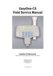
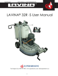
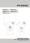
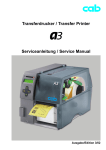
Manuale di servizio GH6
Service manual GH6
Conservare per futura
consultazione.
To be kept for future advice.
MA_B006_GH6_Service manual rev.01
24/02/2011 - 999999000202
Service manual
Type: WM70.C
Contents
Updates ..................................................................................................................................................................................................................................................4
Introduction .........................................................................................................................................................................................................................................5
General product information.....................................................................................................................................................................................................6
Troubleshooting strategy ..............................................................................................................................................................................................................8
Faults and measures ..................................................................................................................................................................................................................... 10
Panel ...................................................................................................................................................................................................................................................... 11
Knob and button descriptions................................................................................................................................................................................................ 11
Display description........................................................................................................................................................................................................................ 11
Programme tables ........................................................................................................................................................................................................................ 12
Programme descriptions ........................................................................................................................................................................................................... 16
Settings................................................................................................................................................................................................................................................. 17
Service menu ................................................................................................................................................................................................................................... 18
Service menu content................................................................................................................................................................................................................. 19
Notes for custom programmes ............................................................................................................................................................................................ 21
Making a custom programme................................................................................................................................................................................................. 22
Fault indicators ................................................................................................................................................................................................................................ 24
Components and measurement values ............................................................................................................................................................................ 25
Thermistor measurement values .......................................................................................................................................................................................... 25
Technical data................................................................................................................................................................................................................................... 26
Tools ...................................................................................................................................................................................................................................................... 26
Wiring diagram ............................................................................................................................................................................................................................... 27
Panel and control card replacement................................................................................................................................................................................... 28
Wash agitator removal ............................................................................................................................................................................................................... 30
Service manual WM70.C
Introduction
You are holding the service manual for WM70.C washing machines.
It should be easy to service a washing machine. It is important that you, as a service technician,
are provided the necessary conditions to work in an efficient and satisfactory manner. Our hope is
that this service manual will prove a useful tool in your daily work.
The type plate is located on the inside of the front door (see image below).
Type designation
WM 70.C
Product number
5
Year Week
Serial number
Service manual WM70.C
General product information
In conjunction with the introduction of the WM70.C (August 2010), our washing machines have
been altered in a number of areas. Here we present the changes to the wash drum and wash
agitators.
s,ARGERWASHDRUM
- 60 litres (previously 50 litres)
- 23 mm deeper, the drum is now 343 mm deep in total (previously 320 mm)
- 30 mm larger diameter, 480 mm in total (previously 450 mm)
s.EWDRUMHOLEPATTERNTOCAUSEASLITTLEWEARASPOSSIBLEONCLOTHING
s.EWAGITATORSTHATIMPROVETHEWASHPROCESS
All cylinder holes flanged to reduce wear on
textiles.
Area with large holes (3.7 mm) to remove
larger objects, such as grit.
Area with smaller holes (2.2 mm) to reduce
wear on textiles.
The angle of the edge of the cylinder, combined
with the shape of the agitators, moves the load
towards the middle of the drum. This improves
drum balance and reduces wear on textiles.
Hourglass-shaped agitators:
s-OVETHELOADTOWARDSTHESMALLERGENTLERHOLES
in the middle of the drum.
s-OVELARGEROBJECTSSUCHASGRITTOWARDSTHE
larger holes at the edges of the drum.
6
Service manual WM70.C
General product information (cont.)
s!UTOMATICDETERGENTCOMPARTMENTCLEANING
- Cleaned after every ten wash cycles between the main wash and the first rinse.
s2EADYFORAUTOMATICDOSING
7
Service manual WM70.C
Troubleshooting strategy
At Asko, we believe in always remaining focused on the customer, and as an ASKO service
technician, you are one of the most important ambassadors of our brand. As such, it is important
that the customer finds the service callout a pleasant experience. Troubleshooting is an important
part of the service callout, and as such we have drawn up a troubleshooting strategy that
describes, in broad terms and step by step, what you need to do to find and diagnose faults.
s!SKTHECUSTOMERTODESCRIBETHEPROBLEM
s#HECKWHETHERTHECUSTOMERSDESCRIPTIONMATCHESANYSERVICECODE
s#HECKTHATTHEMACHINEISCORRECTLYINSTALLED
- Electrical connection
- Drainage
- Water connection
- Machine correctly levelled
No
Fault found?
Yes
Incorrect installation or external factors that affect performance and functionality (for
example, water pressure, electrical supply, drainage).
The machine operates normally. No deviations can be found. The customer probably needs
to be informed about proper use of the machine. If necessary, also inform the customer
about the guarantee conditions and the fact that the customer will be charged for the
callout.
Open the service menu:
1. Check the settings
2. Run a test cycle
3. Note any fault codes
If the above actions do not uncover the fault:
s#ONDUCTGENERALTROUBLESHOOTING5SETHEDOCUMENTATIONAVAILABLEAT3ERVICE3AVER
(service manuals, service memos, wiring diagrams and other documents).
Yes
Fault diagnosed?
Fault found?
No
Yes
Yes
OK?
No
Repair and check function/
safety.
Contact technical support
for assistance.
Carry out the actions
suggested by technical
support.
Satisfied customer!
8
No
Service manual WM70.C
Panel WM70.C
S1
,#$
J1
S4 S5
Programmes:
A total of twenty-two programmes, three of which can be customised via the
service menu. A maximum of ten programmes can be activated/available to the
end user at the same time.
Settings:
&OUR,ANGUAGE#HILDSAFESTART!UTOMATICDOOROPENING4EMPERATURE
Knob and button descriptions
Programme selector
Turn clockwise or anti-clockwise to cycle through the different
programmes and options in the various menus.
Start/Stop button
s3TARTPROGRAMME
s3TOPPROGRAMME0RESSANDHOLDFORSECONDS
Start
Stop
Key button
s/PENSTHEDOORONCETHEPROGRAMMEHASENDED
s/PENSTHEDOORDURINGAPROGRAMMETOADDMORELAUNDRY
s#ONlRMSELECTIONINTHESETTINGSANDSERVICEMENUS
Start
Stop
,#$DESCRIPTION
Temperature
Programme name
Normal wash
9
60°C
1600
Estimated
remaining time
Spin speed
2:20
Service manual WM70.C
Programme tables
The tables present a few examples of the energy, water and time consumption of a few different
programmes. Consumption can vary depending on water pressure, water hardness, water supply
temperature, room temperature, the type and amount of laundry, and variations in the power
supply. The stated times are approximate.
Machine connected to cold water, 6 kg
Programme
Degree of
filling (kg)
Spin (rpm)
Time
(min)
Energy
consumption
(kWh)
Water
consumption
Rinses
1. Normal wash 60°C *
Programme for labelling (also
standard programme for
Swan-labelled machines)
6 kg cotton
Max.
158
1.14
80
5
2. Normal wash 40°C
Programme for labelling (also
standard programme for
Swan-labelled machines)
6 kg cotton
Max.
150
0.65
80
5
3. Heavy wash 90°C
6 kg cotton
Max.
85
2.05
75
3
4. Heavy wash 60°C
6 kg cotton
Max.
65
1.20
65
3
5. White wash 90°C
6 kg cotton
Max.
70
1.70
65
3
6. White/Colour wash 60°C
6 kg cotton
Max.
60
0.80
60
3
7. White/Colour wash 40°C
6 kg cotton
Max.
55
0.50
60
3
8. Super quick wash 60°C
3 kg cotton
800
30
0.60
40
3
9. Super quick wash 40°C
3 kg cotton
800
25
0.35
40
3
10. Synthetics 40°C
3 kg
synthetics
800
25
0.30
40
3
11. Wool/hand 30°C
2 kg wool
800
30
0.35
60
3
12. Rinse programme
3 kg cotton
Max.
15
0.10
15
1
13. MOP wash 90°C
6 kg cotton
Max.
65
1.70
50
2
14. MOP wash 60°C
6 kg cotton
Max.
45
0.85
45
2
15. Micro fibre wash 60°C
6 kg cotton
Max.
50
0.80
50
3
16. Micro fibre wash 40°C
6 kg cotton
Max.
45
0.45
50
3
17. Disinfection 40°C
6 kg cotton
Max.
70
0.75
70
3
18. Disinfection 60°C
6 kg cotton
Max.
80
1.35
70
3
19. Disinfection 90°C
6 kg cotton
Max.
100
2.30
80
3
20. Programme A
Custom
21. Programme B
Custom
22. Programme C
Custom
*Programme tested in accordance with EN 60456/A11/A12/.
10
Service manual WM70.C
Programme tables (cont.)
Machine attached to hot and cold water, 6 kg
Programme
Degree of
filling (kg)
Spin (rpm)
Time
(min)
Energy
consumption
(kWh)
Water
consumption
(hot/cold)
Rinses
1. Normal wash 60°C *
Programme for labelling (also
standard programme for
Swan-labelled machines)
6 kg cotton
Max.
158
1.14
0
80
5
2. Normal wash 40°C
Programme for labelling (also
standard programme for
Swan-labelled machines)
6 kg cotton
Max.
150
0.65
0
80
5
3. Heavy wash 90°C
6 kg cotton
Max.
80
1.80
6
69
3
4. Heavy wash 60°C
6 kg cotton
Max.
60
0.95
6
59
3
5. White wash 90°C
6 kg cotton
Max.
58
1.10
16
49
3
6. White/Colour wash 60°C
6 kg cotton
Max.
48
0.20
16
44
3
7. White/Colour wash 40°C
6 kg cotton
Max.
50
0.25
12
48
3
8. Super quick wash 60°C
3 kg cotton
800
27
0.45
10
30
3
9. Super quick wash 40°C
3 kg cotton
800
22
0.20
6
34
3
10. Synthetics 40°C
3 kg
synthetics
800
23
0.20
5
35
3
11. Wool/hand 30°C
2 kg wool
800
30
0.35
0
60
3
12. Rinse programme
3 kg cotton
Max.
15
0.10
0
15
1
13. MOP wash 90°C
6 kg cotton
Max.
53
1.10
16
34
2
2
14. MOP wash 60°C
6 kg cotton
Max.
33
0.25
16
29
15. Micro fibre wash 60°C
6 kg cotton
Max.
38
0.20
16
34
3
16. Micro fibre wash 40°C
6 kg cotton
Max.
40
0.20
12
38
3
17. Disinfection 40°C
6 kg cotton
Max.
65
0.50
6
64
3
18. Disinfection 60°C
6 kg cotton
Max.
75
1.10
6
64
3
Max.
95
2.05
6
74
3
19. Disinfection 90°C
6 kg cotton
20. Programme A
Custom
21. Programme B
Custom
22. Programme C
Custom
*Programme tested in accordance with EN 60456/A11/A12/.
11
Service manual WM70.C
Programme tables (cont.)
Machine connected to cold water, 8 kg
Programme
Degree of
filling (kg)
Spin (rpm)
Time
(min)
Energy
consumption
(kWh)
Water
consumption
Rinses
1. Normal wash 60°C *
Programme for labelling (also
standard programme for
Swan-labelled machines)
8 kg cotton
Max.
185
1.20
82
5
2. Normal wash 40°C
Programme for labelling (also
standard programme for
Swan-labelled machines)
8 kg cotton
Max.
175
0.70
82
5
3. Heavy wash 90°C
8 kg cotton
Max.
100
2.60
80
3
4. Heavy wash 60°C
8 kg cotton
Max.
80
1.40
70
3
5. White wash 90°C
8 kg cotton
Max.
75
1.95
70
3
6. White/Colour wash 60°C
8 kg cotton
Max.
60
1.05
65
3
7. White/Colour wash 40°C
8 kg cotton
Max.
55
0.75
65
3
8. Super quick wash 60°C
4 kg cotton
800
35
0.80
45
3
9. Super quick wash 40°C
4 kg cotton
800
30
0.55
40
3
10. Synthetics 40°C
4 kg cotton
800
25
0.35
45
3
11. Wool/hand 30°C
3 kg wool
800
30
0.35
60
3
12. Rinse programme
4 kg cotton
Max.
15
0.10
20
1
13. MOP wash 90°C
8 kg cotton
Max.
70
1.90
55
2
14. MOP wash 60°C
8 kg cotton
Max.
50
1.00
50
2
15. Micro fibre wash 60°C
8 kg cotton
Max.
60
1.00
55
3
16. Micro fibre wash 40°C
8 kg cotton
Max.
55
0.65
55
3
17. Disinfection 40°C
8 kg cotton
Max.
80
0.95
75
3
18. Disinfection 60°C
8 kg cotton
Max.
90
1.75
75
3
19. Disinfection 90°C
8 kg cotton
Max.
110
2.90
85
3
20. Programme A
Custom
21. Programme B
Custom
22. Programme C
Custom
*Programme tested in accordance with EN 60456/A11/A12/.
12
Service manual WM70.C
Programme tables (cont.)
Machine attached to hot and cold water, 8 kg
Programme
Degree of
filling (kg)
Spin (rpm)
Time
(min)
Energy
consumption
(kWh)
Water
consumption
(hot/cold)
Rinses
1. Normal wash 60°C *
Programme for labelling (also
standard programme for
Swan-labelled machines)
8 kg cotton
Max.
185
1.20
0
82
5
2. Normal wash 40°C
Programme for labelling (also
standard programme for
Swan-labelled machines)
8 kg cotton
Max.
175
0.70
0
82
5
3. Heavy wash 90°C
8 kg cotton
Max.
95
2.35
7
73
3
4. Heavy wash 60°C
8 kg cotton
Max.
75
1.15
7
63
3
5. White wash 90°C
8 kg cotton
Max.
58
1.35
18
52
3
6. White/Colour wash 60°C
8 kg cotton
Max.
48
0.30
18
47
3
7. White/Colour wash 40°C
8 kg cotton
Max.
50
0.30
14
51
3
8. Super quick wash 60°C
4 kg cotton
800
30
0.60
12
33
3
9. Super quick wash 40°C
4 kg cotton
800
25
0.35
7
33
3
10. Synthetics 40°C
4 kg
synthetics
800
23
0.35
5
40
3
11. Wool/hand 30°C
3 kg wool
800
30
0.35
0
60
3
12. Rinse programme
4 kg cotton
Max.
15
0.10
0
20
1
13. MOP wash 90°C
8 kg cotton
Max.
60
1.25
18
37
2
14. MOP wash 60°C
8 kg cotton
Max.
40
0.35
18
32
2
15. Micro fibre wash 60°C
8 kg cotton
Max.
50
0.30
18
37
3
16. Micro fibre wash 40°C
8 kg cotton
Max.
50
0.30
14
41
3
17. Disinfection 40°C
8 kg cotton
Max.
75
0.70
7
68
3
18. Disinfection 60°C
8 kg cotton
Max.
85
1.50
7
68
3
Max.
105
2.65
7
78
3
19. Disinfection 90°C
8 kg cotton
20. Programme A
Custom
21. Programme B
Custom
22. Programme C
Custom
*Programme tested in accordance with EN 60456/A11/A12/.
13
Service manual WM70.C
Programme descriptions
14
Programme designation
Description
1. Normal wash 60°C
Programme for normally to heavily soiled laundry, whites and colours. Follow the washing
instructions for each garment. 60°C is a good temperature for garments worn next to the skin.
This programme has five rinses.
2. Normal wash 40°C
Programme for normally to heavily soiled laundry, whites and colours. Follow the washing
instructions for each garment. This programme has five rinses.
3. Heavy wash 90°C
Programme for heavily soiled laundry, with dirt that needs to be fully dissolved before the main
wash. A pre-wash is used to do this.
4. Heavy wash 60°C
Programme for heavily soiled laundry, with dirt that needs to be fully dissolved before the main
wash. A pre-wash is used to do this.
5. White wash 90°C
Programme for normally to heavily soiled laundry. Follow the washing instructions for each
garment. 90°C is a good temperature for white and light-coloured cotton, such as bed linen.
6. White/Colour wash 60°C
Programme for normally soiled laundry, whites and colours. Follow the washing instructions for
each garment. 60°C is a good temperature for garments worn next to the skin.
7. White/Colour wash 40°C
Programme for normally soiled laundry, whites and colours. Follow the washing instructions for
each garment.
8. Super quick wash 60°C
Fast programme for laundry that just needs freshening up. Follow the washing instructions for each
garment. Garments worn next to the skin ought to be washed at 60°C.
9. Super quick wash 40°C
Fast programme for laundry that just needs freshening up. Follow the washing instructions for each
garment.
10. Synthetics 40°C
Programme for synthetics, delicate blended materials and permanent press cotton. Suitable for
shirts and blouses. Follow the washing instructions for each garment. Many synthetics will come
clean at 40°C.
11. Wool/hand 30°C
A gentle laundry programme for wool, silk and garments that should be washed by hand. This
programme has a short spin.
12. Rinse programme
This programme performs one cold rinse cycle + spin. Suitable for laundry that just needs to be
dampened.
13. MOP wash 60°C
Programme suitable for different types of mop. The programme has two rinses using much water.
14. MOP wash 90°C
Programme suitable for different types of mop. The programme has two rinses using much water.
15. Micro fibre wash 60°C
Programme for laundry made of micro fibres, such as micro-fibre cloths. The programme has
three rinses with much water in the first rinse.
16. Micro fibre wash 40°C
Programme for laundry made of micro fibres, such as micro-fibre cloths. The programme has
three rinses with much water in the first rinse.
17. Disinfection 40°C
Programme where the temperature reached during the main wash is maintained for 20 minutes.
Disinfection at this temperature requires special detergent.
18. Disinfection 60°C
Programme where the temperature reached during the main wash is maintained for 20 minutes.
Disinfection at this temperature requires special detergent.
19. Disinfection 90°C
Programme where the temperature reached during the main wash is maintained for 10 minutes.
This temperature is sufficient for disinfection without special detergent.
20. Programme 20
Custom
21. Programme 21
Custom
22. Programme 22
Custom
Service manual WM70.C
Settings
Opening the settings menu
Start
Stop
+
På/Av
Start
Stop
Is the machine on? First turn off the power at the main power
switch (S1).
Press and hold the Key button (S5) while simultaneously pressing
the main power switch (S1).
Press the Key button (S5) 5 times within 10 seconds. The settings
menu now opens.
5X
Choosing a setting (an example)
Turn the programme selector (J1) to cycle through the settings menu
options.
1
2
Start
Stop
Turn the programme selector (J1) to cycle through the different options for
that setting.
3
4
5
Press the Key button (S5) to select an item in the settings menu.
Start
Stop
Start
Stop
Press the Key button (S5) to select one of the settings.
Press the Start/Stop button (S4) to save the settings and return to the
programme menu.
Service menu content
Comments
,ANGUAGE
Note: The language used under “Special” in the service menu is not changed
(English only).
US English
English
Svenska
Dansk
Norsk
Suomi
Français
Deutsch
Italiano
Espanol
ȧɣɠɠɘɖɗ
Nederlands
Child-safe
Child-safe Off
Child-safe On
Door opening
Door opening Off
Door opening On
°C/°F
°C
°F
15
You can temporarily disable Child-safe start by pressing
the Start/Stop button and the Key button simultaneously.
Service manual WM70.C
Service menu
Opening the service menu
Start
Stop
+
På/Av
×5
Start
Stop
If the machine is on: First turn off the power at the main power
switch (S1).
Press and hold the Start/Stop button (S4) while simultaneously
pressing the main power switch (S1).
Press the Start/Stop button (S4) 5 times within 5 seconds. The
service menu now opens.
Navigating the service menu
1
2
Start
Stop
Turn the programme selector (J1) to cycle through the different
settings.
3
4
Turn the programme selector (J1) to cycle through the different
service menu options.
- 1 Service
- 2 Settings
- 3 Special
Press the Key button (S5) to select an option in the service menu.
Start
Stop
Press the Key button (S5) to select a setting.
Turn the programme selector (J1) to select one of the options.
5
6
Start
Stop
Start
Stop
7 or
16
Press the Key button (S5) to confirm/save or go back one step.
Press the Start/Stop button (S4) to return to the programme
menu or use the programme selector to make additional choices.
NB:
The different options in the service menu vary in terms of the
number of alternative selections and settings.
Service manual WM70.C
Service menu content
1 Service
11 Info
12 Fault
scenarios
SP: XXXX
Date the software was programmed (Year_Week)
CM: XXXX
Date of manufacture of the control unit (Year_
Week)
SW:
Software version
SW:
Software version
NC:
Number of cycles/programmes run
NC 1:
Number of cycles for Programme 1
NC 2:
Number of cycles for Programme 2
NC 3:
Number of cycles for Programme 3
NC 4:
Number of cycles for Programme 4
NC 5:
Number of cycles for Programme 5
NC 6:
Number of cycles for Programme 6
NC 7:
Number of cycles for Programme 7
NC 8:
Number of cycles for Programme 8
NC 9:
Number of cycles for Programme 9
NC 10:
Number of cycles for Programme 10
Fault 1
Shows current fault. The display shows Fault
name_Programme number_Number of cycles_
Index number.
Example: Thermistor fault_Pr5_9_(1)
Fault 2
Fault 3
Error messages are erased from the system during
a total reset.
13
Diagnostics
2 Settings
Test
Test valve 1
Inlet valve 1 is open.
Test valve 2
Inlet valve 2 is open.
Test valve SM
Inlet valve 1 and 2 are open.
Test valve 3
Inlet valve 3 is open.
Test heater
Heater on up to max. 60°C.
Test motor
The motor normally runs at 49 rpm.
Test drain
The drainage pump runs.
Test spin
The machine runs a spin sequence, the drainage
pump runs.
Test door
The door lock is activated and the door opens.
Returns to the programme menu.
14 Total
reset
The machine is restored to its factory settings.
Returns to the programme menu after Total reset.
15 ABC
reset
The custom programmes (Pr20-Pr22) are reset.
Returns to the programme menu after ABC reset.
Return
Press the Key button (S5) to return to 1 Service.
21 Water
inlet
Cold
22 Max
RPM
400 rpm
Hot
600 rpm
800 rpm
1000 rpm
1200 rpm
1300 rpm
1400 rpm
1500 rpm
1600 rpm
23 Drain
Pump
Valve
17
This function only works for programmes
Pr1-Pr19.
Service manual WM70.C
Service menu content (cont.)
24 Show
temp
Temp Off
Only applies to the disinfection programmes (Pr17-Pr19)
Temp On
25 Change
temp
Pr1-Pr19
26 Programs
Pr1-Pr19
This can be changed in steps of 1°C between -10°C to +10°C. You cannot set a total
temperature that exceeds +92°C.
Select “On” or “Off ”
Programmes can be activated/deactivated. A deactivated programme is not shown on the
display.
A maximum of 10 programmes can be shown on the display in programme mode. If more than
10 programmes are activated, then only the first ten activated programmes are shown on the
display.
If all the programmes have been deactivated, the display only shows “Pr1”.
If the machine is Swan-labelled, “Pr1” and “Pr2” are always activated/On.
27 Spin time
0-300 sec
s%XTENDORSHORTENTHESPINTIMESEC
s)FhSECvISSELECTEDTHEPREPROGRAMMEDSPINTIMEISUSED
s)FATIMEINTHEINTERVALhSECvTOhSECvISSELECTEDTHISTIMEISADDEDTOTHEPRE
programmed spin time.
s4HISFUNCTIONONLYWORKSFORPROGRAMMES0RAND0R
28 Coin
Coin Off
See the wiring diagram for the correct connection and functionality of a slot meter.
Coin On
3 Special
29 Reset
Only production
reset
Used only in production
Return
Press the Key button (S5) to return to 2 Settings.
Pr 20
34 Pre wash
341 Number of
0/1/2/3
342 Water level
Normal water level/High water level
343 Time
1/2/3/4/...../15
344 Heat temp
No heat/25°C/26°C/......./60°C
Return
35 Main wash
351 Temperature
30°C/31°C/...../92°C
352 Water level
Normal water level/High water level
353 Reheat temp
28°C/29°C/...../92°C
354 Reheat time
0min/1min/...../60°C
355 Work time
0min/1min/...../60min
Return
Pr 21
18
36 Rinses
1 Rinse/2 Rinse/...../7 Rinses
37 Extra spin
On/off
38 Spin speed
400/600/800/1000/1200/1300/1400/1500/1600 RPM
39 Spin time
0-300 sec
Return
Press the Key button to return to the previous menu level.
See above
Pr 22
See above
Return
Press the Key button (S5) to return to 3 Special.
Service manual WM70.C
Notes for custom programmes
or
es f
t
o
n
!
ese erence
h
t
f
e
Sav ure re
t
u
f
Make a note of the settings you make when creating custom programmes (Pr20, 21, 22).
Save this note close to the machine
Notes
Pr 20 34 Pre
wash
35 Main
wash
341 Number of
342 Water level
343 Time
344 Heat temp
351 Temperature
352 Water level
353 Reheat temp
354 Reheat time
355 Work time
36 Rinses
37 Extra spin
38 Spin speed
39 Spin time
341 Number of
Pr 21 34 Pre
wash
342 Water level
343 Time
344 Heat temp
35 Main
351 Temperature
wash
352 Water level
353 Reheat temp
354 Reheat time
355 Work time
36 Rinses
37 Extra spin
38 Spin speed
39 Spin time
341 Number of
Pr 22 34 Pre
wash
342 Water level
343 Time
344 Heat temp
35 Main wash
351 Temperature
352 Water level
353 Reheat temp
354 Reheat time
355 Work time
36 Rinses
37 Extra spin
38 Spin speed
39 Spin time
19
Service manual WM70.C
Making a custom programme
You can make three custom programmes. This is done in the service menu. In order for the new
programme to be made available, one of the existing programmes must be deactivated, that is, set
to “Off”, and the new programme set to “On”. See also the “3 Special” section of the “Service
menu content” chapter.
Opening the service menu
Start
Stop
+
På/Av
×5
Start
Stop
If the machine is on: First turn off the power at the main power
switch (S1).
Press and hold the Start/Stop button (S4) while simultaneously
pressing the main power switch (S1).
Press the Start/Stop button (S4) 5 times within 5 seconds. The
service menu now opens.
Programming
Turn the programme selector (J1) to “3 Special”.
1
2
Start
Stop
Turn the programme selector (J1) to cycle through the different
options: Pr20, Pr21, Pr22 and Return.
3
4
Start
Stop
Start
Stop
9
20
Press the Key button to open one of the menus.
Turn the programme selector (J1) to cycle through the different
menu options.
7
8
Press the Key button (S5) to open one of the options, Pr20, Pr21
or Pr22. Now you can create your programme by selecting from
the various options and settings.
Turn the programme selector (J1) to cycle through the different menus:
-34 Pre wash
-35 Main wash
-36 Rinses
-37 Extra spin
-38 Spin speed
-39 Spin time
Return
5
6
Press the Key button (S5) to open the “3 Special” menu.
Start
Stop
Start
Stop
Press the Key button to save the setting and return to the
previous menu level. Repeat steps 5 to 8 to program the
remaining settings.
Once you have finished creating the programme, press the Start/
Stop button (S4) to return to the programme menu.
Service manual WM70.C
Activate the new programme
1
2
Start
Stop
Start
Stop
+
På/Av
×5
If the machine is on: First turn off the power at the main
power switch (S1).
Press and hold the Start/Stop button (S4) while
simultaneously pressing the main power switch (S1).
Press the Start/Stop button (S4) 5 times within 5 seconds.
The service menu now opens.
Turn the programme selector (J1) to “2 Settings”.
3
4
Start
Stop
Press the Key button (S5) to open the “2 Settings” menu.
Turn the programme selector (J1) to “26 Programs”.
5
6
Start
Stop
Turn the programme selector (J1) to select the programme
you want to deactivate.
7
8
Start
Stop
Start
Stop
Start
Stop
21
Press the Key button to open the menu.
Turn the programme selector to “On” to activate the
programme.
13
14
Press the Key button (S5) to confirm/save.
Activate your new programme by turning the programme
selector to the programme you want to activate.
11
12
Press the Key button to open the menu.
Turn the programme selector to “Off” to deactivate the
programme.
9
10
Press the Key button (S5) to open the “26 Programs” menu.
Start
Stop
Press the Key button to confirm/save.
Service manual WM70.C
Fault indicators
Error message
Cause
Action
Over flow fault
Too much water in the machine.
Service action:
Check the machine's level system, inlet valve and drainage
pump. Check for any leaks.
The drainage pump is running but
the machine is empty.
22
Water outlet fault
s4HEDRAINAGEPUMPHASBEEN
running for 3 minutes. Water
remains in the machine.
s4HEWASHCYCLEISSTOPPEDAND
the programme is reset.
1. Check that nothing is stuck in the drainage hose outlet.
2. Check that the drainage pump is not blocked by foreign
objects.
3. Check that there are no kinks in the drainage hose.
Service action:
1. If the pump only runs for a short while (approximately 20
seconds), this indicates a fault in the level system. Check the
level sensor and hoses.
2. Check the wiring and voltage to the pump. If necessary,
replace the pump and/or control unit.
3. After taking corrective action, run the Drain programme
or press the Key (door opening) button to empty the
machine.
Water inlet fault
If the correct water level is not
achieved within five minutes the
wash cycle will be stopped.
1. Check that the tap on the water pipe is open.
Service action:
1. Check that the filter in the machine's water intake is not
blocked.
2. Check the inlet valve. If necessary, replace the valve.
3. Check the voltage to the inlet valve. If there is no voltage,
this could be due to a fault in the level system, wiring or
control unit.
Security fault
The door is open
Close the door
Thermistor fault
1. Thermistor circuit open
2. Thermistor malfunction
3. The measurement value for the
thermistor is <300 : (>120°C)
Service action:
Check the thermistor. Replace if necessary.
Temperature fault
The temperature has increased < Service action:
5°C in ten minutes
Check the thermistor, heater, wiring and level system.
The wash cycle should continue to
the next step of the programme.
Wash motor fault
No signal from the tacho or MCU.
Service action:
Check the output signal from the MCU and the wiring
between the motor and the MCU.
Pressure fault
Indicated if the level drops to
zero within 30 seconds of the first
rinse.
Service action:
Check for leaks.
Service manual WM70.C
Components and measurement values
Item number
Component
Measurement value
80 658 33
CIM motor
Resistances:
Pins 1-3 stator 3.7 :
Pins 1-2 stator 3.6 :
Pins 2-3 rotor 3.6 :
Pins 4-5 tacho 178 :
80 617 03
80 617 04
Heating element 2000 W
Heating element 1000 W
80 761 02
Thermistor
6.1–3.8 k: (at room
temperature 20–30°C)
The thermistor for measuring temperature is
located between the motor cradle and the drum.
The thermistor measures and controls the water
temperature, which can vary from 0 to 92°C. The
heater is disconnected if the thermistor is shortcircuited or disconnected from the programme
control card.
88 012 63
Drainage pump 50 Hz
144 :
88 012 64
Drainage pump 60 Hz
76 :
The drainage pump is combined with an integrated
fine filter trap, which can be cleaned by the user.
If the drainage pump has run for 3 minutes during
draining, the programme stops, resets and a fault
code is indicated on the display. The pump has a
capacity of 20 litres/minute.
80 782 21
,EVELSWITCH
80 762 02
EMC filter 50/60 Hz
680 :
The filter eliminates interference to and from the
machine.
80 793 24
Inlet valve
3.7 k: ± 0.5 k:
Two-way inlet valve, 8 litres/minute
80 798 73
Door lock
122 :
The door lock is electromechanical and equipped
with a magnet.
80 833 15
One-way inlet valve
80 818 07
Motor control
80 806 28
Control unit
80 833 43
Communication unit
80 083 65
Outlet valve
Thermistor measurement values
23
Temp, ºC
Resistance, ohm
0
15806
10
9634
20
6046
25
4841
30
3900
40
2579
50
1744
60
1204
70
848
80
609
85
519
Comment
Electromechanical level switch with two levels (see
wiring diagram). Used to indicate levels for door
opening, heat and overflow.
Service manual WM70.C
Technical data
Height:
850 mm
Width:
595 mm
Depth:
585 mm
Weight:
73 kg
Cylinder volume:
60 l
Max. load capacity
8 kg/6 kg
Spin speed:
800-1600
Connection:
1-phase 16 A, 3-phase 10 A
Heater output:
2000 W/3000 W
Water pressure/inlet valve:
0.1–1 MPa, 1–10 kp/cm2, 10–100 N/cm2 8 l/min
Wash drum and liquid compartment:
Stainless steel
Outer panels:
Powder-coated and hot-galvanised sheet steel or stainless steel
Installation:
Stationary on four adjustable, rubber-clad feet
Water connection:
1.5 m PEX tubing, 3/4"–3/4" or 3/4"–1/2"
Drainage:
1.7 m polypropylene tubing
Protection class:
IP X4
Water consumption (tested normal
programme)
59 litres, 3 rinses (5 kg/6 kg
<72 litres, 5 rinses (6 kg)
<69 litres, 5 rinses (5 kg)
Water consumption (tested normal
programme)
1.02 kWh (6 kg)
0.95 kWh (5 kg)
Electricity consumption, Standby:
- Machine turned off
- Delayed start
- Programme ended
<0.3 W
<6.0 W
<3.0 W
Tools
Torx: T25, T20, T10
Ring spanner: 11/16", 16 mm, 13 mm, 10 mm
Socket screwdriver 10 mm
Extended socket 24 mm + ratchet handle
Allen key 5 mm + small ratchet handle
Plastic hammer
Phillips screwdriver
Wire cutter
24
Service manual WM70.C
Panel and control card replacement
1. Attach the anti-static wristband to a part
of the machine that is earthed!
NB: An anti-static wristband must be used,
otherwise you risk destroying the control
card.
2. Undo the three screws holding the top
cover in place.
3. Remove the top cover.
4. Use a screwdriver to carefully free the
panel. As you do so, carefully angle the panel
outwards.
5. Remove the panel and the cables. NB:
Don't forget to remove the pressure sensor
tube.
30
Service manual WM70.C
Panel and control card replacement (cont.)
6. Carefully pull the programme selector
from the panel.
5. Use a screwdriver to free the control card
from the panel. NB: The control card must
be placed in an ESD-safe bag.
6. Check that the push button, lens and
decorative inlay are in place. Now carefully
press the new control card into place. NB:
Don't forget to replace the rubber seal.
31
Service manual WM70.C
Wash agitator removal
When replacing or cleaning the wash agitators, or when removing items that have fallen through
the wash drum, first you need to remove the agitators. Follow the instructions below.
1. Insert a screwdriver or the like into
the hole on the agitator as illustrated and
carefully pry to the left.
2. Use your other hand to grasp the agitator
and pull it towards you.
,IFTTHEAGITATOR
4. Remove any foreign objects.
5. Place the agitator in the mounting hole
with the letter F towards you. Ensure that
all the agitator fasteners are in their holes
in the drum. Push it away from you until it
fastens.
32
Versione con pompa di scarico
Model with drain pump
2
Pannellatura esterna
Outer casing
Pos
Code
101
Descrizione
Description
Qty
GR36ASK8061817-81 COPERCHIO SUPERIORE GRIGIO
TOP COVER GREY METALLIC
1 Pc's
101-a
GR36ASK8900338
VITE VEDI GR36ASK8902362
SCREW Repl.by 8902362
3 Pc's
101-b
GR36ASK8901413
RONDELLA AZ 4,3 ZINCATA
LOCK WASHER AZ 4,3 GALV
2 Pc's
105
GR36ASK8064198
TRAVERSO DI SUPPORTO, COPERCHIO
SUP.
SUPPORT BEAM, TOP COVER
1 Pc's
105-a
GR36ASK8064255
STRIP DI SPUGNA GOMMATA 2X8 L=272 SPONGE RUBBER STRIP 2X8 L=272 1 Pc's
106
GR36ASK8801174-81 PANNELLO LATERALE COMPLETO WM20
107
GR36ASK8061763
GUIDA PANNELLO FRONTALE/COPERCHIO GUIDE FRONT PLATE/TOP COVER
2 Pc's
108
GR36ASK8061916
SUPPORTO CAVI WMD20 UL4
CABLE HOLDER WMD20 UL4
1 Pc's
111
GR36ASK8064017
MATERASSINO FONO ASSORBENTE
SOUND DEAD.SHEET OUTLET
HOSE
1 Pc's
112
PANN. FRONT. COMPL. SENZA SERRATUGR36ASK8080117-81 RA
FRONT WITHOUT DOOR COMPL.
SIDE PLATE COMPL. WM20
2 Pc's
1 Pc's
113
GR36ASK8080197
AGGANGIO PLASTICO PANNELLO FRONTALE
PLASTIC BRACKET FRONT PLATE
114
GR36ASK8064222
GUIDA IN PLASTICA PER PANNELLO
FORNTALE
PLASTIC GUIDE FRONT PLATE
2 Pc's
114-a
GR36ASK8900327
VITE RTS ST 4,2X13 FZB T20
SCREW RTS ST 4,2X13 FZB T20
2 Pc's
122
GR36ASK8061785
PROTEZIONE POMPA WM20
PUMP GUARD WM20
1 Pc's
123
GR36ASK8061657-81 PORT. EST. POMPA COLORE GRIGIO M.
DOOR OUTLET PUMP GREY METALLIC
1 Pc's
127
GR36ASK8061737
PANNELLO PORTERIORE WM20
REAR PANEL WM20
1 Pc's
127-b
GR36ASK8900338
VITE VEDI GR36ASK8902362
SCREW Repl.by 8902362
11 Pc's
131
GR36ASK8088291
STAFFA TRASPORTO WM70
BEAM TRANSPORT BRACE WM70
1 Pc's
134
GR36ASK8088277
VITE M10X65 TT FZB
SCREW M10X65 TT FZB
1 Pc's
135
GR36ASK8088467
SPINA DI BLOCCO TRASPORTO
PLUG TRANSPORT LOCKING
1 Pc's
136
GR36ASK8065773
COPERTURA TUBO POSTERIORE
HOSE FRAME REAR COVER
2 Pc's
137
GR36ASK8076070
CONNESSIONE TUBO 3/4"-3/4" NERO
CONNECT. PIPE 3/4"-3/4" BLACK
2 Pc's
138
GR36ASK8050805
SUPPORTO TUBO UL4
HOLDER, HOSE UL4
1 Pc's
138
GR36ASK8088270
SUPPORTO TUBO LATERALE
HOSE HOLDER SIDEPLATE
2 Pc's
138-a GR36ASK8002263
STRIP CAVI 200 mm
CABLE STRIP 200 MM
1 Pc's
139
GR36ASK8061618
FONDO WMD20
BOTTOM WMD20
1 Pc's
140
GR36ASK8059334
PIEDE IN GOMMA D35xM10 CON DADO
RUBBER FOOT D35xM10 INC. NUT
4 Pc's
3
2 Pc's
Pannellatura esterna
Outer casing
4
Parte superiore
Upper session
Pos
Code
501
GR36ASK8076029
Descrizione
Description
TRAVERSO FRONTALE
FRONTBEAM
1 Pc’s
501-a GR36ASK8900338
VITE VEDI GR36ASK8902GR362
SCREW Repl.by 8902GR362
2 Pc’s
501-b GR36ASK8901413
RONDELLA AZ 4,3 ZINCATA
LOCK WASHER AZ 4,3 GALV
2 Pc’s
503
COMPARTIMENTO DETERGENTI COMPLETO DETERGENT COMPARTMENT COMPL.
GR36ASK8081666
1 Pc’s
503-a GR36ASK8901970
VITE PTK 40X12 A2 WN1452 T20
SCREW PTK 40X12 A2 WN1452 T20
1 Pc’s
503-b GR36ASK8902072
VITE PT KB40X10 WN1442 ZINCATA
SCREW PT KB40X10 WN1442 GALV
1 Pc’s
506
SOFFIETTO DI INGRESSO UL4
BELLOW HOSE INLET UL4
1 Pc’s
CLIP TUBO 57,5
HOSE CLIP 57,5
1 Pc’s
GR36ASK8064692
506-a GR36ASK8063607
AIR BREAK WM20 UL4
VENTILATION HOSE WM20 UL4
1 Pc’s
510-a GR36ASK8052730
510
GR36ASK8061736
CLIP TUBO 21,0
HOSE CLIP 21,0
1 Pc’s
513
GR36ASK8076363
TUBO GOMMA WRAS 350mm
WRAS RUBBER HOSE 350mm
2 Pc’s
515
GR36ASK8083880
ELETT. VALVOLA INGRESSO ACQUA 2-VIE
INLET VALVE 2-WAY
1 Pc’s
SCREW MRT-TT 4X10 FZB T20
515-a GR36ASK8901097
VITE MRT-TT 4X10 FZB T20
526
GR36ASK8078971
UNITA’ COMPLETA PER PARTI ELETTRICHE UNIT FOR ELECTR. COMP.
1 Pc’s
527
GR36ASK8076202
FILTRO EMC CON INDUTTORE
EMC-FILTER WITH INDUCTOR
1 Pc’s
DADO M6M8 BH8 ZINCATO
NUT M6M8 BH8 GALV
1 Pc’s
527-a GR36ASK8901155
2 Pc’s
527-b GR36ASK8901419
RONDELLA AZ 8,4 ZINCATA
LOCK WASHER AZ 8,4 GALV
1 Pc’s
529
GR36ASK8079714
SET CAVI MC C CIM-A W UL4
CABLE SET MC C CIM-A W UL4
1 Pc’s
529
GR36ASK8082568
SET CAVI P WM UL4
CABLE SET P WM UL4
1 Pc’s
529
GR36ASK8082569
SET CAVI MC P WM UL4
CABLE SET MC P WM UL4
1 Pc’s
529
GR36ASK8083063
SET CAVI IV3 WM60.C UL4
CABLE SET IV3 WM60.C UL4
1 Pc’s
529
GR36ASK8079710
SET CAVI IV WM UL4
CABLE SET IV WM UL4
1 Pc’s
529
GR36ASK8079716
SET CAVI N AP LL WM UL4
CABLE SET N AP LL WM UL4
1 Pc’s
529
GR36ASK8083057
SET CAVI EL WM60.C UL4
CABLE SET EL WM60.C UL4
1 Pc’s
529
GR36ASK8089033
SET CAVI MOTOR A WM UL4
CABLE SET MOTOR A WM UL4
1 Pc’s
531
GR36ASK8089766
PRESSOSTATO WM70
LEVEL SWITCH WM70
1 Pc’s
532
GR36ASK8080832
TUBO GOMMA 5X8X75
RUBBER HOSE 5X8X75
1 Pc’s
533
GR36ASK8080617
TUBO GOMMA 5X8X260
RUBBER HOSE 5X8X260
1 Pc’s
534
GR36ASK8051843
CONNETTORE AD Y 05
Y-PIPE 05
1 Pc’s
GR36ASK8061997
ANTISCHIACCIAMENTO TUBO PRESSOSTAGUARD, LEVELSWITCH HOSE WM20
TO WM20
2 Pc’s
SUPPORTO CAVI GRANDE
1 Pc’s
535
5GR36 GR36ASK8061975
537
GR36ASK8089748
CABLE HOLDER BIG
PONTE POSTERIORE
CROSS BEAM
1 Pc’s
537-a GR36ASK8900327
VITE RTS ST 4,2X13 FZB T20
SCREW RTS ST 4,2X13 FZB T20
5 Pc’s
539
MORSETTIERA 5-POLI
TERMINAL BLOCK 5-POLE
1 Pc’s
VITE MRT-TT 4X10 FZB T20
SCREW MRT-TT 4X10 FZB T20
1 Pc’s
GR36ASK8061660
539-a GR36ASK8901097
541
GR36ASK8078983
CAVO PRINCIPALE 5X1.5X2000 90C
MAINS CABLE 5X1.5X2000 90C
1 Pc’s
547
GR36ASK8089723
MOLLA DI BILANCIAMENTO
BALANCING SPRING
2 Pc’s
548
GR36ASK8064179
CONTATTORE 4S 50/60HZ
CONTACTOR 4S 50/60HZ
1 Pc’s
559
GR36ASK8083315
ELETT. VALVOLA INGRESSO ACQUA 1-VIA INLET VALVE 1-WAY
565
GR36ASK8058559
1 Pc’s
FILTRO SOPPRESSORE RADIOINTERF. F19 RADIOINTERF.SUPP. FILTER F19
2 Pc’s
565-a GR36ASK8901155
DADO M6M8 BH8 ZINCATO
NUT M6M8 BH8 GALV
1 Pc’s
565-b GR36ASK8901419
RONDELLA AZ 8,4 ZINCATA
LOCK WASHER AZ 8,4 GALV
1 Pc’s
5
Parte superiore
Upper session
6
Parte inferiore
Lower session
Pos
Code
Descrizione
Description
Qty
201
GR36ASK8801454
KIT AMMORTIZZATORE WM70
SPRINGLEG KIT WM70
1 Pc's
202
GR36ASK8088443
GOMMINO PER AMM. SUPERIORE
RUBBER BUFFER SPRING LEG
4 Pc's
203
GR36ASK8088444
GOMMINO PER AMM. INFERIORE
RUBBER BUFFER SPRING LEG
4 Pc's
204
GR36ASK8088445
AMM. IN GOMMA DELLO STELO DEL
RUBBER DAMPER PISTON ROD
PISTONE
4 Pc's
206
GR36ASK8088644
MOTORE CIM WM70
MOTOR CIM WM70
1 Pc's
207
GR36ASK8058261
TUBO SOSPENSIONE MOTORE
12X191
SPAC.TUBE MOTOR SUSP. 12X191
2 Pc's
208
GR36ASK8063591
VITE 8.8 M8x205 FZB
SCREW 8.8 M8x205 FZB
2 Pc's
211
GR36ASK8089672
UNITA' CONTROLLO MOTORE CIM-A MOTOR CONTROL UNIT CIM-A
1 Pc's
211-a
GR36ASK8901097
VITE MRT-TT 4X10 FZB T20
SCREW MRT-TT 4X10 FZB T20
1 Pc's
211-b
GR36ASK8901322
RONDELLA SRB 4,3X12X1 ZINCATA WASHER SRB 4,3X12X1 GALV.
1 Pc's
212
GR36ASK8083420
SUPPORTO UNITA' CONTROLLO MOHOLDER CONTROL UNIT(MOTOR) UL4
TORE UL4
1 Pc's
215
GR36ASK8076733
SOFFIETTO POMPA DI SCARICO
VAR.1 UL4
BELLOWS HOSE PUMP VAR.1 UL4
1 Pc's
215
GR36ASK8801292
SOFFIETTO BALL/WASHER
BELLOWS HOSE WITH BALL/WASHER
1 Pc's
215-a
GR36ASK8063262
CLIP PER TUBO 80.0-708
HOSE CLIP 80.0-708
1 Pc's
215-b
GR36ASK8056471
CLIP PER TUBO 42,5
HOSE CLIP 42,5
1 Pc's
215-c
GR36ASK8052083
CLIP PER TUBO (Vedi GR36ASK8084609)
HOSE CLIP Repl.by 8084609
1 Pc's
219
GR36ASK8061924
TRAPPOLA ARIA WM20 UL4
PRESSURE CHAMBER WM20 UL4
1 Pc's
219-c
GR36ASK8052083
CLIP PER TUBO (Vedi GR36ASK8084609)
HOSE CLIP Repl.by 8084609
1 Pc's
220
GR36ASK8080831
TUBO IN GOMMA 5X8X520
RUBBER HOSE 5X8X520
1 Pc's
221
GR36ASK8801263
POMPA DI SCARICO COMPLETA
50HZ
DRAIN PUMP COMPL. SYNCR. 50HZ
1 Pc's
221-a
GR36ASK8801186
INSERTO DI TENUTA
SEAL PUMP INSERT HANNING SYNC.
1 Pc's
221-b
GR36ASK8801185
INSERTO DI TENUTA WM20
PUMP INSERT HANNING SYNC. WM20
1 Pc's
222
GR36ASK8061649
TAMPONE IN GOMMA, POMPA DI
SCARICO WM20
RUBBER BUFFER,DRAIN PUMP WM20
2 Pc's
223
GR36ASK8061796
ANELLO IN GOMMA VALVOLA DI
SCARICO WM20
RUBBER RING DRAINPUMP WM20
1 Pc's
224
GR36ASK8061725
TUBO DI SCARICO 190mm WM20
DRAIN HOSE 190mm WM20
1 Pc's
224-a
GR36ASK8052731
CLIP PER TUBO 14,8
HOSE CLIP 14,8
1 Pc's
226
GR36ASK8061998
SCARICO ESTERNO WM20 UL4
OUTLET HOSE WM20 UL4
1 Pc's
226-a
GR36ASK8056491
CLIP PER TUBO 30,1
HOSE CLIP 30,1
1 Pc's
230
GR36ASK8061738
SUPPORTO TERMISTORE WM20
HOLDER THERMISTOR WM20
1 Pc's
231
GR36ASK8076102
TERMISTORE WM
THERMISTOR WM
1 Pc's
232
GR36ASK8061976
CAVO SUPPORTO PICCOLO
CABLE HOLDER SMALL
2 Pc's
240
GR36ASK8061703
RESISTENZA RISC. 2000W 230V
FUSIBILATA UL4
HEATINGEL. 2000W 230V FUSE UL4
1 Pc's
250
GR36ASK8061704
RESISTENZA RISC. 1000W 230V
FUSIBILATA UL4
HEATINGEL. 1000W 230V FUSE UL4
1 Pc's
7
Parte inferiore
Lower session
8
Vasca e parti correlate
Cylinder and related parts
Pos
Code
Descrizione
Description
Qty
1 Pc's
301
GR36ASK8082933-81
FRONTALE PORTA COMPLETO WM60.C
FRONT DOOR COMPL. WM60.C
302
GR36ASK8082934-81
TELAIO FRONTE PORTA ESTERNO
FRAME FRONT DOOR OUTER PART 1 Pc's
303
GRGR36ASK8082937-49 TELAIO FRONTE PORTA INTERNO
FRAME FRONT DOOR INNER PART 1 Pc's
304
GRGR36ASK8061685
FRONT GLASS D306x42mm WM20 1 Pc's
VETRO D306x42mm WM20
305
GR36ASK8078973
BLOCCO PORTA
LOCK HOOK
1 Pc's
306
GR36ASK8081128
GUARNIZIONE FRONTALE WM60
SEALING FRONT DOOR WM60
1 Pc's
307
GR36ASK8801321
KIT SICUREZZA FRONTALE VETRO
KIT SECURING PLATE FRONT
GLASS
1 Pc's
311
GR36ASK8082563-81
FRONTE ESTERNO VASCA WM60.C
COVER PLATE OUTER WM60.C
1 Pc's
313
GR36ASK8082561
CERNIERA COMPLETA WM60.C
HINGE WM60.C COMPL.
1 Pc's
313-a GR36ASK8901097
VITE MRT-TT 4X10 FZB T20 2 Pc's
SCREW MRT-TT 4X10 FZB T20
2 Pc's
314
GAP GUARNIZIONE
GAP SEALING
1 Pc's
GR36ASK8076561-81
315
GR36ASK8081693
FRONTE VASCA INTERNO WM70
COVER INNER WM70
1 Pc's
316
GR36ASK8076563
CONTRAPPESO 5,1 KG
BALANCE WEIGHT 5,1 KG
2 Pc's
316-a GR36ASK8901135
VITE M6SF-TT 8X25 FZB
SCREW M6SF-TT 8X25 FZB
4 Pc's
318
SERRATURA
DOOR LOCK
1 Pc's
318-a GR36ASK8902087
VITE PTK 40X14 WN1452 FZB T20
SCREW PTK 40X14 WN1452 FZB
T20
2 Pc's
319
GR36ASK8076566
APERTURA DI EMERGENZA DELLA PORTA EMERGENCY OPENER DOOR LOCK 1 Pc's
320
GR36ASK8079959-UL
COPERTURA SERRATURA PORTA
321
GR36ASK8081689
TIMPANO FRONTALE DI MANTENIMENTO
FRONT GABLE CONTAINER WM70 1 Pc's
WM70
322
GR36ASK8081696
GUARNIZIONE FRONTALE DEL WM70
SEALING STRIP FRONT GABLE
WM70
1 Pc's
323
GR36ASK8081695-P
ANELLO DI TENSIONAMENTO WM70
TENSIONRING WM70
1 Pc's
325
GR36ASK8081676-P
VASCA COMPLETA D480 WM70
DRUM D480 COMPL. WM70
1 Pc's
326
GR36ASK8081678
SBATTITORE WM70
DRUM PADDLE WM70
3 Pc's
GR36ASK8079873
COVER DOOR LOCK
1 Pc's
327
GR36ASK8081649
CINGHIA J5 1225
DRIVE BELT J5 1225
1 Pc's
329
GR36ASK8801276
KIT CASSETTA GUARNIZIONE
KIT SEALING CASSETTE
1 Pc's
330
GR36ASK8056314
CUSCINETTO 6206 2RS MTSRL
BALL BEARING 6206 2RS MTSRL
2 Pc's
331
GR36ASK8801456
CONTENITORE COMPLETO WM70 2 RESICONTAINER COMPL. WM70 2 EL.
STENZE
1 Pc's
332
GR36ASK8056810
RONDELLA 37x30,5x0,5
SCALE WASHER 37x30,5x0,5
1 Pc's
333
GR36ASK8056376
PULEGGIA COMPLETA D292
PULLEY COMPL. D292
1 Pc's
335
GR36ASK8901052
VITE BUFO 8,8 10X25 ZINCATA
SCREW BUFO 8,8 10X25 GALV
1 Pc's
339
GR36ASK8083250-81
COPERTURA CERNIERA WM60.C
COVER HINGE WM60.C
1 Pc's
342
GR36ASK8089887
GUIDA-2 VETRO PORTA
GUIDE-2 GLASS DOOR
1 Pc's
9
Vasca e parti correlate
Cylinder and related parts
10
Pannello di controllo
Control panel
Pos
Code
Descrizione
Description
Qty
401
GR36ASK8080887-69
PANELLO WMD60.2 MECH.
PANEL WMD60.2 MECH.
1 Pc's
402
GR36ASK8079749
CORDINO O-RING IN GOMMA
O-RING CORD CELLULAR RUBBER
1 Pc's
407
GR36ASK8081672-81
COPERCHIO DISPENSER CON FORO LID DETERGENT DISP. W. HOLE
1 Pc's
411
GR36ASK8081748-69
PULSANTE START/STOP PER WM
PUSHBUT. START/STOP PRINTED WM
1 Pc's
413
GR36ASK8081710-69
PULSANTE PRINCIPALE WMD60.2
PUSHBUTTON MAIN SWITCH WMD60.2
1 Pc's
430
GR36ASK8088612
SCHEDA ELETT. DI CONTROLLO
WM70.C
CONTROL UNIT WM70.C
1 Pc's
435
GR36ASK8083316
LENTE 0-OPTZIONI WMD60.2
LENS 0-OPTIONS WMD60.2
1 Pc's
439
GR36ASK8083075-69
MANOPOLA OEM WMD60.2
KNOB OEM WMD60.2
1 Pc's
440
GR36ASK8083375-81
MEMBRANA SERIGRAFATA 0-OPTIONS WMD60.C
DECOR PLATE 0-OPTIONS WMD60.C
1 Pc's
468
GR36ASK8076209
CATENA DI TERRA WM UL4
GROUND CHAIN WM UL4
1 Pc's
469
GR36ASK8086440
SET CAVI BOX GETTONIERA
CABLE SET COIN BOX
1 Pc's
469
GR36ASK8083064
SET CAVI FUNZ. GETTONIERA
WMD60.C
CABLE SET COIN OP. WMD60.C
1 Pc's
471
GR36ASK8081664
VASCHETTE DISPENSER
DETERGENT COMPARTMENT
1 Pc's
472
GR36ASK8081665
VASCHETTA DISPENSER SIFONATA SIPHON DETERGENT COMPARTMENT
11
1 Pc's
Schema elettrico
Circuit diagram
12
Versione con valvola di scarico
Model with drain valve
13
Pannellatura esterna
Outer casing
Pos
Code
Descrizione
Description
Qty
101
GR36ASK8061817-81
COPERCHIO SUPERIORE GRIGIO
TOP COVER GREY METALLIC
1 Pc’s
101-a
GR36ASK8900338
VITE VEDI GR36ASK8902362
SCREW Repl.by 8902362
3 Pc’s
101-b
GR36ASK8901413
RONDELLA AZ 4,3 ZINCATA
LOCK WASHER AZ 4,3 GALV
2 Pc’s
105
GR36ASK8064198
TRAVERSO DI SUPPORTO, COPERCHIO SUP.
SUPPORT BEAM, TOP COVER
1 Pc’s
105-a
GR36ASK8064255
STRIP DI SPUGNA GOMMATA 2X8
L=272
SPONGE RUBBER STRIP 2X8 L=272 1 Pc’s
106
GR36ASK8801174-81
PANNELLO LATERALE COMPLETO
WM20
SIDE PLATE COMPL. WM20
2 Pc’s
107
GR36ASK8061763
GUIDA PANNELLO FRONTALE/COPERCHIO
GUIDE FRONT PLATE/TOP COVER
2 Pc’s
108
GR36ASK8061916
SUPPORTO CAVI WMD20 UL4
CABLE HOLDER WMD20 UL4
3 Pc’s
111
GR36ASK8064017
MATERASSINO FONO ASSORBENTE SOUND DEAD.SHEET OUTLET HOSE 1 Pc’s
112
GR36ASK8084355-81
FRONTALE (VALVOLA) SENZA CLIP FRONT(VALVE) WITHOUT DOOR
PORTA
CPL.
1 Pc’s
112-a
GR36ASK8900338
VITE VEDI GR36ASK8902362
SCREW Repl.by 8902362
2 Pc’s
112-b
GR36ASK8900327
VITE RTS ST 4,2X13 FZB T20
SCREW RTS ST 4,2X13 FZB T20
2 Pc’s
113
GR36ASK8080197
AGGANGIO PLASTICO PANNELLO
FRONTALE
PLASTIC BRACKET FRONT PLATE
2 Pc’s
114
GR36ASK8064222
GUIDA IN PLASTICA PER PANNELLO
PLASTIC GUIDE FRONT PLATE
FORNTALE
2 Pc’s
114-a
GR36ASK8900327
VITE RTS ST 4,2X13 FZB T20
2 Pc’s
120
GR36ASK8064097
SPINA PROTEZIONE SCARICO VALPLUG GUARD OUTLET VALVE
VOLA
1 Pc’s
122
GR36ASK8061930
PROTEZIONE SCARICO VALVOLA
WM20
1 Pc’s
123
GR36ASK8061657-81
PORT. EST. POMPA COLORE GRIGIO DOOR OUTLET PUMP GREY METALM.
LIC
1 Pc’s
127
GR36ASK8061737
PANNELLO PORTERIORE WM20
REAR PANEL WM20
1 Pc’s
127-b
GR36ASK8900338
VITE VEDI GR36ASK8902362
SCREW Repl.by 8902362
11 Pc’s
131
GR36ASK8088291
STAFFA TRASPORTO WM70
BEAM TRANSPORT BRACE WM70
1 Pc’s
134
GR36ASK8088277
VITE M10X65 TT FZB
SCREW M10X65 TT FZB
1 Pc’s
135
GR36ASK8088467
SPINA DI BLOCCO TRASPORTO
PLUG TRANSPORT LOCKING
1 Pc’s
136
GR36ASK8065773
COPERTURA TUBO POSTERIORE
HOSE FRAME REAR COVER
2 Pc’s
137
GR36ASK8076070
CONNESSIONE TUBO 3/4”-3/4”
NERO
CONNECT. PIPE 3/4”-3/4” BLACK
2 Pc’s
138
GR36ASK8007513
TUBO SCARICO (90 GRADI)
OUTLET HOSE (90 DEGREES)
1 Pc’s
139
GR36ASK8061618
FONDO WMD20
BOTTOM WMD20
1 Pc’s
140
GR36ASK8059334
PIEDE IN GOMMA D35xM10 CON
DADO
RUBBER FOOT D35xM10 INC. NUT
4 Pc’s
14
SCREW RTS ST 4,2X13 FZB T20
GUARD OUTLET VALVE WM20
Pannellatura esterna
Outer casing
15
Parte inferiore
Lower session
Pos
Code
Descrizione
Description
Qty
201
GR36ASK8801454 KIT AMMORTIZZATORE WM70
SPRINGLEG KIT WM70
1 Pc’s
202
GR36ASK8088443 GOMMINO PER AMM. SUPERIORE
RUBBER BUFFER SPRING LEG
4 Pc’s
203
GR36ASK8088444 GOMMINO PER AMM. INFERIORE
RUBBER BUFFER SPRING LEG
4 Pc’s
204
GR36ASK8088445
RUBBER DAMPER PISTON ROD
4 Pc’s
206
GR36ASK8088644 MOTORE CIM WM70
MOTOR CIM WM70
1 Pc’s
207
GR36ASK8058261 TUBO SOSPENSIONE MOTORE 12X191
SPAC.TUBE MOTOR SUSP. 12X191
2 Pc’s
208
GR36ASK8063591 VITE 8.8 M8x205 FZB
SCREW 8.8 M8x205 FZB
2 Pc’s
211
GR36ASK8089672 UNITA’ CONTROLLO MOTORE CIM-A
AMM. IN GOMMA DELLO STELO DEL PISTONE
MOTOR CONTROL UNIT CIM-A
1 Pc’s
211-a GR36ASK8901097 VITE MRT-TT 4X10 FZB T20
SCREW MRT-TT 4X10 FZB T20
1 Pc’s
211-b GR36ASK8901322 RONDELLA SRB 4,3X12X1 ZINCATA
WASHER SRB 4,3X12X1 GALV.
1 Pc’s
HOLDER CONTROL UNIT(MOTOR) UL4
1 Pc’s
SUPPORTO UNITA’ CONTROLLO MOTORE
UL4
212
GR36ASK8083420
215
GR36ASK8088582 SOFFIETTO VALVOLA DI SCARICO UL4
BELLOWS HOSE OUTLET VALVE UL4
1 Pc’s
219
GR36ASK8061924 TRAPPOLA ARIA WM20 UL4
PRESSURE CHAMBER WM20 UL4
1 Pc’s
HOSE CLIP Repl.by 8084609
1 Pc’s
219-c GR36ASK8052083 CLIP PER TUBO VEDI GR36ASK8084609
220
GR36ASK8080831 TUBO IN GOMMA 5X8X520
RUBBER HOSE 5X8X520
1 Pc’s
221
GR36ASK8008365 VALVOLA DI SCARICO MDB-2 454R
OUTLET VALVE MDB-2 454R
1 Pc’s
221-a GR36ASK8901969 VITE MRT-TT 5x12 FZB T20
SCREW MRT-TT 5x12 FZB T20
2 Pc’s
222
HOLDER, OUTLET VALVE WM20
1 Pc’s
GR36ASK8062114 SUPPORTO, VALVOLA SCARICO WM20
222-a GR36ASK8901969 VITE MRT-TT 5x12 FZB T20
226
SCREW MRT-TT 5x12 FZB T20
GR36ASK8062111 TUBO SCARICO, VALVOLA SCARICO WM20 OUTLET HOSE, OUTLET VALVE WM20
2 Pc’s
1 Pc’s
226-a GR36ASK8051391 CLIP PER TUBO 60,5
HOSE CLIP 60,5
2 Pc’s
230
HOLDER THERMISTOR WM20
1 Pc’s
GR36ASK8061738 SUPPORTO TERMISTORE WM20
231
GR36ASK8076102 TERMISTORE WM
THERMISTOR WM
1 Pc’s
232
GR36ASK8061976 CAVO SUPPORTO PICCOLO
CABLE HOLDER SMALL
2 Pc’s
240
GR36ASK8061703
243
GR36ASK8050702 TUBO A T, SCARICO
T-TUBE, OUTLET
1 Pc’s
243-a GR36ASK8051391 CLIP PER TUBO 60,5
HOSE CLIP 60,5
1 Pc’s
243-b GR36ASK8901322 RONDELLA SRB 4,3X12X1 ZINCATA
WASHER SRB 4,3X12X1 GALV.
2 Pc’s
243-c GR36ASK8901097 VITE MRT-TT 4X10 FZB T20
SCREW MRT-TT 4X10 FZB T20
2 Pc’s
250
RESISTENZA RISC. 2000W 230V FUSIBIHEATING EL. 2000W 230V FUSE UL4
LATA UL4
RESISTENZA RISC. 1000W 230V FUSIBIGR36ASK8061704
HEATING EL. 1000W 230V FUSE UL4
LATA UL4
16
1 Pc’s
1 Pc’s
Parte inferiore
Lower session
17
Schema elettrico
Circuit diagram
18
19
Divisione della Ali S.p.A.
Via Masiere, 211/C - 32037 Sospirolo – BL - Italy
Codice Fiscale e Partita IVA IT 00872030150
e-mail: [email protected] http : // www.grandimpianti.com
Tel. +39 0437 848 711 - Fax +39 0437 879 108
Sede Legale: via Camperio, 9 - 20123 Milano
Capitale Sociale € 51.000.000 I.V.
R. E. A. MI n. 862551 - Reg. Imp. MI n. 160786
Unicredit Banca – BIC SWIFT UNCRIT2VBLW
IBAN - IT53 R03226 11900 000004602298