1
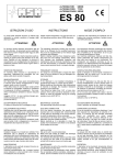
ISTRUZIONI PER IL MONTAGGIO
ASSEMBLING INSTRUCTIONS
OPERATION DE MONTAGE
MONTAGEANLEITUNG
INSTRUCCIONES PARA EL MONTAJE
FORMA B3/B9 MONOSUPPORTO
B3/B9 FORM SINGLE-BEARING
FORME B3/B9 MONOPALIER
FORM B3/B9 EINZELAUFHÄNGUNG
FORMA B3/B9 MONOSOPORTE
ATTENZIONE: prima del montaggio verificare che le
sedi coniche di accoppiamento (sia dell'alternatore
che del motore) siano regolari e ben pulite.
1) Fissare la flangia F al motore utilizzando viti e
rondelle adeguate allo scopo (1A).
2) Applicare il tirante T per il fissaggio assiale del
rotore avvitandolo a fondo sulla sporgenza
dell'albero motore (1A).
3) Fissare l'alternatore alla flangia con le 4 viti V1 e
relative rosette R1 in dotazione (coppia di
serraggio 25Nm) (1B).
4) Bloccare assialmente il rotore applicando la
rosetta R2 (attenzione: utilizzare rosetta
Ø16/8,4) e serrando il dado autobloccante D2
sul tirante T con chiave dinamometrica (coppia di
serraggio 30Nm ±10%).
Attenzione: prima di applicare il dado osservare che
la porzione filettata del tirante penetri nel rotore
permettendo così un sicuro bloccaggio.
4a)Ruotare il portaspazzole PS fino a posizionarlo
nella propria sede, in modo che le spazzole
facciano contatto sul collettore ad anelli, e fissarlo
avvitando la vite V5. (1B-1)
CAUTION: before assembling verify that the conical
coupling parts are in order and clean.
1) Fasten the flange F to the motor using screws
and washers adequate to the purpose. (1A).
2) Apply the rod T for the axial clamping of the rotor,
and screw it tight on the engine shaft. (1A).
3) Fasten the complete alternator to the flange using
the 4 screws V1 and washers R1 provided
(driving torque 25Nm). (1B).
4) Lock axially the rotor by placing the washer R2
(warning: use Ø16/8,4 washer) and tight
the self-locking nut D2 on the rod T, using a
torque spanner (driving torque 30Nm ±10%).
Caution: before applying the nut, make sure that the
threaded part of the rod enters the rotor, in order
to obtain a tight lock.
4a)Rotate the PS brush-holder until it fits into its
housing in such way that the brushes make
contact with the slip ring, and then fasten it in place
using the V5 screw. (1B-1)
Always check to make sure that the brushes are
suitably centred on the slip rings
Verificare sempre che il posizionamento delle
spazzole sia ben centrato sugli anelli del collettore
ATTENTION: Avant le montage verifier que les
siéges coniques pour l`accouplement (de
l`alternateur et du moteur) soient en ordre et propres.
ACHTUNG: Vor der Montage ist zu überprüfen, daß
die Kegelsitze gleichmäßig und sauber sind.
ATENCION: Antes del montaje, verificar que las
partes cónicas del acoplamiento estén en orden y
bien limpias.
1) Den Flansch F mit Hilfe entsprechender Schrauben
und Unterlegscheiben am Motor befestigen. (1A).
1) Fixez la bride F au moteur à l'aide de vis et de
rondelles appropriées.(1A).
2) Monter la tige centrale T pour la fixation axiale, la
vissant a fond sur le bout d`arbre du moteur (1A).
2) Die Zugstange T für die Achsbefestigung des
Rotors durch vollständiges Einschrauben auf dem
Überstand der Motorwelle anbringen (1A).
3) Fixez l'alternateur complet à la bride à l'aide des 4
vis V1 et des rondelles correspondantes R1
fournies en dotation (couple de serrage 25Nm).
(1B)
3) Den kompletten Wechselstromgenerator mit Hilfe
von 4 Schrauben V1 und entsprechenden
Unterlegscheibe R1 am Flansch befestigen
(Anzugsmoment 25Nm) (1B)
4) Bloquer axialement le rotor, en utilisant la rondelle
R2 (avertissement: utilise la rondelle
Ø16/8,4) et vissant a fond l`écrou autobloquant
D2 sur la tige centrale T en utilisant la clef
dynamometrique (couple de serrage 30Nm
±10%).
4) Den Rotor in Achsenrichtung blockieren, indem
die Unterlegscheibe R2 (Warnung: verwende
Ø16/8,4 Unterlegscheibe) angebracht und
die selbstsperrende Mutter D2 auf der Zugstange
T mit einem Drehmomentenschlüssel angezogen
wird (Drehmoment 30Nm ±10%).
Attention: avant de mettre l`écrou, controler que la
partie fileteé de la tige centrale entre dans le
rotor, permettant ainsi un bloquage fermé.
Achtung: Bevor die Mutter angebracht wird ist
sicherzustellen, daß der Gewindeteil der
Zugstange in den Rotor eingeschraubt wird, um
eine sichere Blockierung zu ermöglichen.
4a) Tournez le porte-brosses PS jusqu'à ce qu'il soit
mis en place, et de telle manière que les brosses
soient au contact du collecteur à bagues. Puis fixezle en vissant la vis V5 (1B-1)
Assurez-vous toujours que le positionnement des
brosses est bien centré sur les anneaux du
collecteur
1) Fijar la brida F al motor utilizando los tornillos y
arandelas adecuados para ello. (1A)
2) Montar el tirante T para la fijación axial del rotor
atornillándolo a fondo sobre el saliente del cigüeñal
del motor (1A)
3) Fijar el alternador completo a la brida con los 4
tornillos V1 y correspondientes arandelas R1
incluidas (par de torsión 25Nm). (1B)
4) Bloquear axialmente el rotor utilizando la arandela
R2 (advertencia: utilizar la arandela
Ø16/8,4) y apretando la tuerca autoblocante D2
sobre el tirante T con llave dinamométrica (par de
apriete 30Nm ±10%)
Atención : antes de montar la tuerca asegurarse de
que la parte roscada del tirante entra en el rotor,
permitiendo así un blocaje seguro.
4a) Girar el portaescobillas PS hasta que entre en
su alojamiento, de manera que las escobillas estén
en contacto con el colector de anillos, y fijarlo
apretando el tornillo V5 (1B-1)
4a) Den Bürstenhalter PS bis zum Einrasten in der
Aufnahme drehen, so dass die Bürsten mit dem
Schleifring in Berührung kommen, und diesen durch
Anziehen der Schraube V5 befestigen (1B-1)
Comprobar siempre que la posición de las
escobillas esté bien centrada en los anillos del
colector
Stets überprüfen, dass die Bürsten mittig an den
Ringen des Schleifrings ausgerichtet sind
1B-1
1A
1B
V5
PS
R1
F
V1
R
T
V
R2
T
usare rosetta
use washer
Ø16/8,4
D2