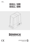
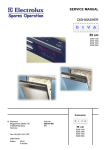
Download BULL 424 BULL 624
Transcript
L8542352 05/2008 rev1 BULL 424 BULL 624 UNIONE NAZIONALE COSTRUTTORI AUTOMATISMI PER CANCELLI, PORTE SERRANDE ED AFFINI 1 260 83 92 330 330 140 210 326 2 3 A 5 32 10 0 4 75 D R X B T2 0 30 = = T 5 24mm max 20mm 3 7 6 P P D 68 mm 103 mm C C V V 8 9 ≈1 mm C 10 D R min= 0 mm max= 20 mm MIN = 92 mm MAX = 112 mm 11 BULL.P3 34 4 mm 12 1÷ 3c m F S A G 13 C L 5 14 8 2x 7 4 RG 58 5 1,5 4x 0,3 5 6 1 2 4 n mi 5 , 1 3 x 30V 2 2x 3 0,3 5 H 3x 15 6 0,3 5 5 Dichiarazione CE di conformità per macchine (Direttiva 89/392 CE, Allegato II, parte B) - Divieto di messa in servizio Fabbricante: Automatismi Benincà SpA. Indirizzo: Via Capitello, 45 - 36066 Sandrigo (VI) - Italia Dichiara che: l’automazione per cancelli scorrevoli modello BULL 424 - 624. • è costruita per essere incorporata in una macchina o per essere assemblata con altri macchinari per costituire una macchina considerata dalla Direttiva 98/37 CE, come modificata; • non è dunque conforme in tutti i punti alle disposizioni di questa Direttiva; • è conforme alle condizioni delle seguenti altre Direttive CE: Direttiva bassa tensione 73/23/CEE, 93/68/CEE. Direttiva compatibilità elettromagnetica 89/336/CEE, 93/68/CEE. e inoltre dichiara che non è consentito mettere in servizio il macchinario fino a che la macchina in cui sarà incorporata o di cui diverrà componente sia stata identificata e ne sia stata dichiarata la conformità alle condizioni della Direttiva 98/37 CE e alla legislazione nazionale che la traspone, vale a dire fino a che il macchinario di cui alla presente dichiarazione non formi un complesso unico con la macchina finale. Benincà Luigi, Responsabile legale. Sandrigo, 08/04/2007. AVVERTENZE E' vietato l'utilizzo del prodotto per scopi o con modalità non previste nel presente manuale. Usi non corretti possono essere causa di danni al prodotto e mettere in pericolo persone e cose. Si declina ogni responsabilità dall'inosservanza della buona tecnica nella costruzione dei cancelli, nonché dalle deformazioni che potrebbero verificarsi durante l'uso. Conservare questo manuale per futuri utilizzi. L'installazione deve essere effettuata da personale qualificato nel pieno rispetto delle normative vigenti. I materiali dell'imballaggio non devono essere lasciati alla portata dei bambini in quanto fonte di potenziale pericolo. Non disperdere nell'ambiente i materiali di imballo, ma separare le varie tipologie (es. cartone, polistirolo) e smaltirle secondo le normative locali. L’installatore deve fornire tutte le informazioni relative al funzionamento automatico, manuale e di emergenza dell'automazione, e consegnare all’utilizzatore dell’impianto le istruzioni d’uso. Prevedere sulla rete di alimentazione un interruttore/sezionatore onnipolare con distanza d’apertura dei contatti uguale o superiore a 3 mm. Verificare che a monte dell’impianto elettrico vi sia un interruttore differenziale e una protezione di sovracorrente adeguati. Alcune tipologie di installazione richiedono il collegamento dell'anta ad un impianto di messa a terra rispondente alle vigenti norme di sicurezza. Durante gli interventi di installazione, manutenzione e riparazione, togliere l’alimentazione prima di accedere alle parti elettriche. Le descrizioni e le illustrazioni presenti in questo manuale non sono impegnative. Lasciando inalterate le caratteristiche essenziali del prodotto il fabbricante si riserva il diritto di apportare qualsiasi modifica di carattere tecnico, costruttivo o commerciale senza impegnarsi ad aggiornare la presente pubblicazione. 7 INTRODUZIONE INSTALLAZIONE Ci congratuliamo con Voi per aver scelto il motoriduttore BULL. Tutti gli articoli della vasta gamma Benincà sono il frutto di una ventennale esperienza nel settore degli automatismi e di una continua ricerca di nuovi materiali e di tecnologie all’avanguardia. Proprio per questo, oggi siamo in grado di offrire dei prodotti estremamente affidabili che, grazie alla loro potenza, efficacia e durata, soddisfano pienamente le esigenze dell’utente finale. Tutti i nostri prodotti sono coperti da garanzia. Inoltre, una polizza R. C. prodotti stipulata con primaria compagnia assicurativa copre eventuali danni a cose o persone causati da difetti di fabbricazione. FIG.1 Dimensioni di ingombro del motoriduttore espresse in mm. NOTIZIE GENERALI Automazione con alimentazione monofase 24Vdc per cancelli scorrevoli, disponibili nelle versioni: BULL 424 per cancelli con peso massimo pari a 350kg BULL 624 per cancelli con peso massimo pari a 600kg Il BULL è un monoblocco dal design raffinato e di ridotte dimensioni; costituito da un gruppo di alluminio al cui interno sono stati collocati il motore e un sistema di riduzione irreversibile realizzato con materiali ad alta resistenza. Il BULL è dotato di finecorsa con funzionamento a molla. Uno sblocco di emergenza a chiave personalizzata permette la movimentazione manuale del cancello in mancanza di corrente. La sicurezza antischiacciamento è garantita da un dispositivo elettronico (encoder e sensore amperometrico) che rileva la presenza di eventuali ostacoli. VERIFICHE PRELIMINARI Per un buon funzionamento dell’automazione per scorrevoli, la porta da automatizzare, dovrà rispondere alle seguenti caratteristiche: - la rotaia di guida e relative ruote devono essere opportunamente dimensionate e manutenzionate (onde evitare eccessivi attriti durante lo scorrimento del cancello. - durante il funzionamento la porta non deve presentare eccessivi ondeggiamenti. - la corsa di apertura e chiusura deve essere limitata da un arresto meccanico (secondo normativa di sicurezza vigente). DATI TECNICI BULL 424 230Vac 50Hz Alimentazione 24Vdc Alimentazione motore Potenza assorbita Assorbimento Coppia 80 W 120 W 0,4 A 0,5 A 12 Nm 20 Nm 80% (uso intensivo) Intermittenza di lavoro IP54 Grado di protezione Classe di isolamento F Temp. funzionamento -20°C / +70°C Peso max. cancello 350kg Velocità apertura 12 m/min Peso 10 m/min <70 dB Rumorosità Lubrificazione 600kg M4 Modulo cremagliera 8 BULL 624 CASTROL OPTITEMP LP2 9 kg 10 kg MESSA IN POSA DELLA PIASTRA DI FONDAZIONE FIG.2-3-4-5 E' molto importante rispettare la quota X di Fig.2 il cui valore dipende dal tipo di cremagliera utilizzato: X = 52 mm per cremagliera in Nylon X = 49 mm per cremagliera in Ferro 12x30mm Predisporre un tubo corrugato (Fig.2 -A) per il passaggio dei cavi di alimentazione ed il collegamento degli accessori. Verificare che al termine del fissaggio la piastra di fondazione risulti perfettamente parallela all'anta. Fissaggio con tasselli su fondo in cemento (Fig.3) Eseguire 4 fori diam.10mm, utilizzando la piastra di fondazione la come dima di foratura. Mediante 4 tasselli a pressione in acciaio "T" ancorare saldamente a terra la piastra di fondazione utilizzando le 4 barre filettate M8x150mm "B" e relativi dadi "D" e rosette "R". Sono disponibili in commercio dei sistemi di fissaggio alternativi come ad esempio ancoraggi con fascetta ad espansione (Fig.3 -T2) da inserire nel foro con alcuni colpi di martello. Fissaggio a cementare (Fig.4) In questo caso dopo aver predisposto un adeguato scavo per la fondazione, piegare le barre filettate come indicato in Fig.4. Annegare le barre nel cemento, prestando attenzione al livello della piastra. Attendere il consolidamento del getto di cemento. In Fig. 5 è raffigurata la piastra a fissaggio ultimato. Indipendentemente dal tipo di fissaggio verificare che le barre filettate siano saldamente ancorate a terra e che sporgano per almeno 24mm (44 mm per montaggio sopraelevato). FISSAGGIO CREMAGLIERA FIG.6-7-8 Cremagliera in nylon (Fig.6). Posizionare la cremagliera ad una altezza di 68 mm dalla mezzeria dell’asola di fissaggio alla base sulla quale andrà fissata la piastra di fondazione; in tale punto forare e filettare M6 il cancello. Rispettare il passo di dentatura P anche tra un tratto di cremagliera e l’altro; a tale scopo può essere utile accoppiare un’altro spezzone di cremagliera (Part. C) Cremagliera in Fe 12x30mm (Fig.7). Posizionare i distanziali D saldandoli o avvitandoli sul cancello ad una altezza di 103 mm dalla mezzeria dell’asola di fissaggio alla base sulla quale andrà fissata la piastra di fondazione. Fissare infine la cremagliera rispettando i punti 4.3 e 4.4. Rispettare il passo di dentatura P anche tra un tratto di cremagliera e l’altro; a tale scopo può essere utile accoppiare un’altro spezzone di cremagliera (Part. C) Fissare infine la cremagliera con le viti V, avendo cura, una volta installato l’attuatore, che rimanga circa 1mm di gioco tra cremagliera e ruota di trascinamento (vedi Fig.8); a tale scopo usufruire delle asole sulla cremagliera. POSIZIONAMENTO ED ANCORAGGIO ATTUATORE FIG.9-10 Posizionare il motoriduttore sulla piastra di fondazione con l'ingranaggio centrato rispetto alla cremagliera. Sbloccare l'automazione e verificare che l'ingranamento sia corretto su tutta la corsa della cremagliera, eventualmente aggiustare l'allineamento agendo sulle apposite asole. Bloccare il motoriduttore alla base fissando con forza i 4 dadi D interponenedo le rondelle R. Applicare i due carter copriviti C. Nel caso la cremagliera sia già installata in una posizione più elevata rispetto al pignone, è possibile sollevare la piastra (massimo 20mm) portando i dadi e le rondelle sotto alla piastra come illustrato in Fig.10. Se una predisposizione dei cavi di collegamento rende difficoltoso il fissaggio della piastra standard è disponibile la piastra opzionale BULL.P3 (Fig.11) che consente di alzare di circa 34mm la quota di installazione dell'attuatore facilitando il passaggio dei cavi. POSIZIONAMENTO STAFFE DEI FINECORSA FIG.12 Portare manualmente il cancello in apertura lasciando una luce da 1 a 3cm a seconda del peso del cancello tra il portone stesso e l’arresto meccanico A; fissare quindi la staffa del finecorsa S mediante i grani G in modo che il microinterruttore finecorsa F sia premuto. Ripetere poi l’operazione con il portone in chiusura. N.B.: La staffa del finecorsa deve essere posizionata in modo tale da permettere l’arresto del cancello senza che questo vada in collisione contro l’arresto meccanico. MANOVRA MANUALE FIG.13 In caso di mancanza dell’energia elettrica o di guasto, per azionare manualmente l'anta procedere come segue : - Inserita la chiave personalizzata C, farla ruotare in senso antiorario e tirare la leva L. - Il motoriduttore è così sbloccato ed è possibile movimentare manualmente l'anta. - Per ristabilire il normale funzionamento richiudere la leva L ed azionare il cancello manualmente fino ad ingranamento avvenuto. COLLEGAMENTI ELETTRICI FIG.14 Per il collegamento elettrico dell'automazione e per la regolazione delle modalità di funzionamento, consultate il manuale istruzioni della centrale di comando. In particolare, la taratura della sensibilità del dispositivo antischiacciamento (encoder) deve essere effettuata nel rispetto delle normative vigenti. Ricordiamo inoltre che è obbligatorio effettuare il collegamento di messa a terra utilizzando l'apposito morsetto. La Fig.10 riporta cablaggi da predisporre per una installazione standard. Prima di procedere con il passaggio dei cavi verificate il tipo di cablaggio richiesto per gli accessori effettivamente utilizzati. La quota H rappresenta l'altezza di installazione delle fotocellule, si consiglia una distanza compresa tra i 40 ed i 60 cm. Legenda componenti: 1 Motoriduttore con centrale incorporata BULL 2 Cremagliera M4 Nylon/Fe 3 Staffe dei finecorsa 4 Fotocellule 5 Fermi meccanici 6 Selettore a chiave o tastiera digitale 7 Lampeggiante 8 Antenna BATTERIE TAMPONE FIG.15 E' disponibile come accessorio opzionale il kit batterie tampone BULL24.CB che consente il funzionamento dell'automazione anche in caso di interruzione di alimentazione di rete. Le batterie sono installabili all'interno del motoriduttore, fissate mediante una staffa sul retro del contenitore della centrale, come indicato in Fig.14. Per ulteriori informazioni consultate le istruzioni fornite con il prodotto. ATTENZIONE La polizza RC prodotti, che risponde di eventuali danni a cose o persone causati da difetti di fabbricazione, richiede l’utilizzo di accessori originali Benincà. 9 EC Declaration of Conformity regarding machines (Directive 89/392 CE, Annex II B) - No servicing Manufacturer: Automatismi Benincà SpA. Address: Via Capitello, 45 - 36066 Sandrigo (VI) - Italia We herewith declare that: the automatic system for sliding gates, BULL 424 - 624 model. • is intended to be incorporated into a machine or assembled together with other devices to form a machine in compliance with the EC Directive 98/37, as amended; • therefore, is not in every respect complying with this Directive; • is complying with provisions set forth by the following other EC Directive: EC Low voltage Directive (73/23/EEC, 93/68/EEC). EC Directive of Electromagnetic Compatibility (89/336/EEC, 93/68/EEC) Moreover, we herewith declare that the system shall not be put into service until the machine in which the same will be incorporated or of which it will become a component, is acknowledged compliant with the EC Directive 98/73 and applicable national legislation and a related declaration of conformity is drawn up. In other words, no servicing shall be carried out until the system under this declaration does not form one single final machine with other components. Benincà Luigi, Legal responsible. Sandrigo, 08/04/2008. WARNING The product shall not be used for purposes or in ways other than those for which the product is intended for and as described in this manual. Incorrect uses can damage the product and cause injuries and damages. The company shall not be deemed responsible for the non-compliance with a good manufacture technique of gates as well as for any deformation, which might occur during use. Keep this manual for further use. Qualified personnel, in compliance with regulations in force, shall install the system. Packaging must be kept out of reach of children, as it can be hazardous. For disposal, packaging must be divided the various types of waste (e.g. carton board, polystyrene) in compliance with regulations in force. The installer must supply all information on the automatic, manual and emergency operation of the automatic system and supply the end user with instructions for use. 10 An omnipolar switch/section switch with remote contact opening equal to, or higher than 3mm must be provided on the power supply mains.. Make sure that before wiring an adequate differential switch and an overcurrent protection is provided. Pursuant to safety regulations in force, some types of installation require that the gate connection be earthed. During installation, maintenance and repair, cut off power supply before accessing to live parts. Descriptions and figures in this manual are not binding. While leaving the essential characteristics of the product unchanged, the manufacturer reserves the right to modify the same under the technical, design or commercial point of view without necessarily update this manual. INTRODUCTION Congratulations on your choice of a BULL gear motor. All items included in Benincà’s wide product range stem from twenty year of our experience in the sector of automatic systems, always striving to find new materials and advanced technologies. For this reason, nowadays we are able to offer you extremely reliable products that, thanks to their power, efficiency and long-lasting features, entirely meet the end user’s requirements. All our products are covered by a guarantee. Furthermore, an R.C. insurance policy signed with a primary insurance company, covers any injuries or damages caused by manufacturing faults. GENERAL INFORMATION This automatic system, with 24VDC single-phase power supply for sliding gates, is available in the following versions: BULL 424 for gates with maximum weight equal to 350kg BULL 624 for gates with maximum weight equal to 600kg BULL is a monobloc system featuring a refined design and reduced dimensions. The motor and an irreversible reduction system, manufactured with high resistant materials, are housed in an aluminium container. BULL is equipped with spring limit switches. The customised key emergency release allows to open and close the gate in case of power failure. Anti-crash safety is ensured by an electronic device (encoder and amperometric sensor) which detects any obstacle present. PRELIMINARY CHECKS For a good operation of the automatic system for sliding gates, the gate or door shall meet the following features: - the track and relevant wheels must feature correct sizes and must undergo adequate maintenance (in order to avert excessive friction during the sliding of the gate). - during operation, the door shall not excessively oscillate. - a mechanical stopper (according to regulations in force) shall limit the opening and closing movements. SPECIFICATIONS BULL 424 230Vac 50Hz Power supply 24Vdc Power supply, motor Power drawn Current drawn Torque BULL 624 80 W 120 W 0,4 A 0,5 A 12 Nm 20 Nm 80% (intensive use) Work jogging IP54 Protection level F Insulation Class -20°C / +70°C Operating temperature Gate max. weight 350kg Opening speed 12 m/min Weight 10 m/min <70 dB Noise Lubrication 600kg M4 Rack module CASTROL OPTITEMP LP2 9 kg 10 kg INSTALLATION FIG.1 Overall dimensions of the gear motor expressed in mm. POSITIONING OF THE FOUNDATION PLATE FIG.2-3-4-5 It is very important to keep to dimension X shown in Fig.2. This value depends on the type of rack used: X = 52 mm for rack in nylon X = 49 mm for rack in iron, 12x30mm Preset a corrugated tube (Fig.2 -A) for the passage of power supply cables and connection wires for the accessories. Check that, at the end of the fitting, the foundation plate is perfectly parallel with respect to the wing. Fit the system with screw anchors on the bottom of the cement (Fig.3). Drill 4 holes, diam.10mm, by using the foundation plate as drilling template. Tightly anchor the foundation plate to ground through the 4 “T” steel screw anchors and the 4 “B” threaded bars, M8x150mm and corresponding “D” nuts and “R” washers. Alternative fitting systems are available on the market, e.g. anchoring with retaining expansion band (Fig.3 -T2) to be inserted in the hole with some hammer strokes. Fitting to be cemented (Fig.4) In this case, after providing an adequate foundation hole, bend the threaded bars as shown in Fig.4. Submerse the bars in cement, paying attention to the level of the plate. Wait that the cement hardens. Fig. 5 shows the completed fitting plate. Regardless of the type of fitting, check that the threaded bars are firmly anchored to ground and that they protrude for at least 24mm (44 mm for raised installation). FITTING OF THE RACK FIG.6-7-8 Rack in nylon (Fig.6). Position the rack at a height of 68 mm from the centre line of the fixing slot provided on the base on which the foundation plate will be fitted. At that height, drill a hole on the gate and provide for a M6 threading. Keep to the P tooth pitch, even from a section of rack and another. To this purpose, it could be useful to join another section of rack (Part. C) Rack in Fe 12x30mm (Fig.7). Position the spacers D by welding them or fitting them with screws to the gate, at 103 mm height from the centre line of the fixing slot provided on the base on which the foundation plate will be fitted. Fix the rack by following points 4.3 and 4.4. Keep to the P tooth pitch, for all sections of the rack. To this purpose, it could be useful to connect another section of rack (Part. C) Then fix the rack with V screws, taking care, once the actuator is installed, that 1-mm backlash is left between the rack and the tow wheel (seei Fig.8). To this purpose, use the slots on the rack. POSITIONING AND ANCHORING OF THE ACTUATOR FIG.9-10 Position the gear motor on the foundation plate with the gear centred with respect to the rack. Release the automatic system and check that the gear be correctly positioned along the entire stroke of the rack. If required, adjust the alignment by using the special slots. Fix the gear motor to the base by firmly tightening the 4 nuts D and inserting the R. Apply the two screw covers C. 11 If the rack is already installed in a position which is higher than the pinion, the plate can be raised (20 m maximum) by moving the nuts and the washers under the plate, as shown in Fig.10. If the connecting cables already present make it difficult to fix the standard plate, the optional plate BULL P3 (Fig. 11) can be used, thus allowing to raise the actuator installation by about 34 mm and facilitating the passage of cables. POSITIONING OF THE LIMIT SWITCH BRACKETS FIG.12 Manually open the gate and leave a clearance from 1 to 3cm according to the weight of the gate between the main door and the mechanical stopper A. Fix the bracket to the limit switch S by using the grains G, so that the limit switch microswitch F is pressed. The same operation should be repeated with gate in the closing phase. N.B.: The limit switch bracket should be positioned so that the gate can be stopped without hitting the mechanical stopper. MANUAL OPERATION FIG.13 Should a power failure or malfunction occurs, to manually operate the gate proceed as follows: - After inserting the customised key C, turn it anti-clockwise and pull the lever L. - The gear motor is unlocked and the gate can be moved by hand. - To return to the normal operating mode, close the lever L again and manually activate the gate until it is geared. WIRE DIAGRAM FIG.14 For the wire connections of the system and to adjust the operating modes, please refer to the Instruction Manual of the control unit. In particular, the anti-crash device (encoder) should be adjusted according to regulations in force. Please remember that the device should be earthed by means of the appropriate terminal. Fig.10 shows wiring for a standard installation. Before proceeding to wiring, check that the type of cables used is consistent with those required for accessories. Dimension H stands for the installation height of photocells. A clearance between 40 and 60 cm is advisable. Key of components: 1 Gear motor with incorporated BULL control unit 2 M4 rack, Nylon/Fe 3 Limit switch brackets 4 Photocells 5 Mechanical stoppers 6 Key selector or digital keyboard 7 Flashing light 8 Antenna BUFFER BATTERIES FIG.15 An optional kit of buffer batteries BULL24.CB is available. This permits the operation of the system also in case of power failure. The batteries can be installed inside the gear motor, fixed through a bracket on the rear of the container of the control unit, as shown in Fig.14. For further information, please see instructions supplied with the product. 12 WARNING The RC product insurance policy, which covers any injuries or damages to objects caused by manufacturing defects, requires the use of Benincà’s original accessories. EG-Konformitätserklärung für Maschinen (Richtlinie 89/392 EG, Anhang II, Teil B) – Inbetriebsetzen verboten Hersteller: Automatismi Benincà SpA. Adresse: Via Capitello, 45 - 36066 Sandrigo (VI) - Italia Wir erklären, dass: die Automation für Schiebetore Modell BULL 424 - 624 • hergestellt worden ist, um in Maschinen eingebaut oder in Verbindung mit anderen Maschinen verwendet zu werden, wodurch die Maschine laut EG-Richtlinie 98/37 als umgeändert gilt; • die Automation entspricht daher nicht allen Punkten der Vorschriften dieser Richtlinie; • sie entspricht folgenden EG-Richtlinien: Niederspannungs-Richtlinie 73/23/EWG, 93/68/EWG. Richtlinie über die elektromagnetische Verträglichkeit 89/336/EWG, 93/68/EWG. Wir erklären zudem, dass die Maschine/Anlage in welche oder in Verbindung mit welcher die Automation installiert wird, nicht in Betrieb gesetzt werden darf, bis sie identifiziert und laut EG-Richtlinie 98/37 sowie laut den nationalen Gesetzen, die zur Umsetzung der EG-Richtlinie erlassen wurden, als konform erklärt worden ist. Die hier genannte Automation muss daher mit der Maschine als ein Ganzes als konform erklärt werden. Benincà Luigi, Rechtsvertreter Sandrigo, 08/04/2008. HINWEISE Das Produkt darf nicht für andere Zwecke oder auf andere Weise verwendet werden, als in der vorliegenden Anleitung beschrieben. Ein ungeeigneter Gebrauch kann das Produkt beschädigen und eine Gefahr für Personen und Sachen darstellen. Wir übernehmen keinerlei Haftung für Schäden, die sich aus einer unsachgerechten Montage der Tore und aus daraus folgenden Verformungen ergeben können. Bewahren Sie dieses Handbuch für Nachschlagzwecke auf. Die Installation darf nur von qualifizierten Fachleuten laut den geltenden Vorschriften vorgenommen werden. Das Verpackungsmaterial fern von Kindern halten, da es eine potentielle Gefahr darstellt. Das Verpackungsmaterial nicht ins Freie werfen, sondern je nach Sorte (z.B. Pappe, Polystyrol) und laut den örtlich geltenden Vorschriften entsorgen. Der Installateur hat dem Benutzer alle Informationen über den automatischen, manuellen Betrieb sowie den NotBetrieb der Automatik zusammen mit der Bedienungsanleitung zu liefern. Das Stromnetz muss mit einem allpoligen Schalter bzw. Trennschalter ausgestattet sein, dessen Kontakte einen Öffnungsabstand gleich oder größer als 3 aufweisen.. Kontrollieren, ob der elektrischen Anlage ein geeigneter Differentialschalter und ein Überspannungsschutzschalter vorgeschaltet sind. Einige Installationstypologien verlangen den Anschluss des Flügels an eine Erdungsanlage laut den geltenden Sicherheitsnormen. Während der Installation, der Wartung und der Reparatur, die Anlage stromlos machen bevor an den elektrischen Teilen gearbeitet wird. Die in diesem Handbuch enthaltenen Beschreibungen und Abbildungen sind nicht verbindlich. Ausgenommen der Haupteigenschaften des Produkts, behält sich der Hersteller das Recht vor eventuelle technische, konstruktive oder kommerzielle Änderungen vorzunehmen ohne dass er vorliegende Veröffentlichung auf den letzten Stand bringen muss. 13 EINLEITUNG INSTALLATION Wir gratulieren Ihnen für den Erwerb des Antriebs BULL. Alle Artikel der breiten Produktpalette von Benincà sind das Ergebnis einer zwanzigjährigen Erfahrung auf dem Gebiet der Automationen und der ständigen Forschung nach neuen Materialien und den neusten Technologien. Daher sind wir in der Lage äußerst zuverlässige Produkte anzubieten, die durch ihre Leistung, Funktionstüchtigkeit und Lebensdauer allen Erfordernissen des Endkunden nachkommen können. Alle unsere Produkte sind durch eine Garantie gedeckt. Zudem deckt eine Haftpflichtversicherung, die mit einer wichtigen Versicherungsgesellschaft abgeschlossen worden ist, eventuelle Schäden oder Unfälle die sich aus Produktionsmängeln ergeben sollten. ABB.1 Außenmaße des Antriebs in mm. VERLEGUNG DER FUNDAMENTPLATTE ABB.2-3-4-5 Sehr wichtig: das Maß X der Abb. 2 unbedingt beachten, da es von dem verwendeten Zahnstangentyp abhängig ist: X = 52 mm für Zahnstangen aus Nylon X = 49 mm für Zahnstangen aus Eisen 12x30 mm Ein Wellrohr (Abb. 2-A) für die Stromkabel und die Zubehöranschlüsse verlegen. Sicherstellen, das nach der Befestigung, die Fundamentplatte genau parallel zum Flügel liegt. ALLGEMEINE INFORMATIONEN Automatik mit einphasiger Speisung 24Vdc für Schiebetore, in folgenden Ausführungen erhältlich: BULL 424 für Tore mit einem maximalen Gewicht von 350 kg BULL 624 für Tore mit einem maximalen Gewicht von 600 kg BULL ist ein Monoblock mit raffiniertem Design und beschränkten Maßen. Das Produkt besteht aus einem AluGehäuse im Inneren welches ein Motor und ein irreversibles Reduziersystem aus äußerst widerstandsfähigem Material untergebracht sind. BULL ist mit einem Endschalter mit Federbetrieb ausgestattet. Eine Notfall-Schlüsselentsicherung gestattet es das Tor bei Stromausfall von Hand zu bedienen. Die Quetschsicherheit ist durch eine elektronische Vorrichtung (Encoder und Stromsensor) gewährleistet, die eventuelle Hindernisse erkennt. VORBEREITENDE PRÜFUNGEN Für den einwandfreien Betrieb der Automatik für Schiebetore, muss das Tor nachstehende Eigenschaften aufweisen: - Schiene und Räder müssen entsprechend dimensioniert sein und gewartet werden (um eine übermäßige Reibung beim Gleiten des Schiebetors zu vermeiden). - Während des Betriebs darf das Tor nicht starken Schwankungen ausgesetzt werden. - Die Öffnungsweite und das Schließen muss durch einen mechanischen Endanschlag begrenzt werden (laut den geltenden Sicherheitsvorschriften). TECHNISCHE DATEN BULL 424 Speisung BULL 624 230Vac 50Hz Motorenspeisung 24Vdc Leistungsaufnahme 80 W Stromaufnahme 0,4 A 0,5 A 12 Nm 20 Nm Drehmoment Intermittierender Betrieb 80% (intensiver Gebrauch) IP54 Schutzklasse F Isolationsklasse -20°C / +70°C Betriebstemperatur Max. Torgewicht 350kg 12 m/min Gewicht 14 10 m/min <70 dB Geräuschpegel Schmierung 600kg M4 Zahnstangenmodul Öffnungsgeschwindigkeit 120 W CASTROL OPTITEMP LP2 9 kg 10 kg Befestigung mit Dübeln an dem Betonuntergrund (Abb. 3) 4 Löcher mit einem Durchmesser von 10 mm bohren und die Fundamentplatte als Schablone zur Hilfe nehmen. Mit den 4 T-förmigen Spreizdübeln aus Stahl die Fundamentplatte am Boden fest verankern und dazu die 4 Gewindestäbe M8x150 mm „B“ und die entsprechenden Muttern „D“ und Unterlegscheiben „R“ verwenden. Im Handel sind auch alternative Befestigungssysteme erhältlich, wie Verankerungen mit Spreizbändern (Abb. 3-T2), die in das Loch mit einem Hammer geschlagen werden. Die Verankerungsstelle mit Beton abschließen (Abb. 4). In diesem Fall, nach der Vorbereitung der Fundamentgrube, die Gewindestäbe wie in Abb. 4 gezeigt, biegen. Die Stäbe im Beton einbetten und dabei auf die Nivellierung der Platte achten. Den Beton aushärten lassen. Die Abb. 5 zeigt die fertig befestigte Platte. Unabhängig davon, welche Befestigungsart verwendet wurde, sicherstellen dass die Stäbe fest im Boden verankert sind und mindestens 24 mm (44 mm bei überhöhte Montage) herausragen. ZAHNSTANGE BEFESTIGEN ABB.6-7-8 Zahnstange aus Nylon (Abb. 6). Die Zahnstange auf eine Höhe von 68 mm von der Mittellinie der Befestigungsöse an der Basis, an welche die Fundamentplatte befestigt werden soll, positionieren. An dieser Stelle ein Loch bohren und am Tor ein Gewinde M6 schneiden. Den Zahnschritt P auch zwischen dem einen und anderen Zahnstangeabschnitt beachten. Zu diesem Zweck kann es von Vorteil sein, ein weiteres Zahnstangestück zu verwenden (Einzelheit C). Zahnstange aus Eisen 12x30 mm (Abb. 7). Die Distanzstücke D am Tor auf eine Höhe von 103 mm von der Mittellinie der Befestigungsöse an der Basis, an welche die Fundamentplatte befestigt werden soll, positionieren und anschweißen oder festschrauben. Die Zahnstange schließlich befestigen und die Punkte 4.3 und 4.4 beachten. Den Zahnschritt P auch zwischen dem einen und anderen Zahnstangenabschnitt beachten. Zu diesem Zweck kann es von Vorteil sein, ein weiteres Zahnstangenstück zu verwenden (Einzelheit C). Schließlich die Zahnstange mit den Schrauben V befestigen und nach der Installation des Aktuators darauf achten, dass noch 1 mm Spiel zwischen der Zahnstange und der Schlepprolle (siehe Abb. 8) übrig bleibt. Dazu die Ösen an der Zahnstange verwenden. POSITIONIEREN UND VERANKERN DES AKTUATORS ABB.9-10 Den Getriebemotor auf die Fundamentplatte positionieren und das Zahnrad im Verhältnis zur Zahnstange zentrieren. Die Automatik entsichern und kontrollieren ob die Zahnräder in der Zahnstange über den gesamten Hub richtig einrasten. Ggf. die Ausrichtung über die entsprechenden Ösen korrigieren. Den Getriebemotor an der Basis befestigen; dazu die 4 Muttern D mit den zwischenliegenden Scheiben R festziehen. Die beiden Schraubenabdeckungen C anbringen. Falls die Zahnstange im Verhältnis zum Ritzel höher installiert wurde, kann die Platte wie in Abb. 10 gezeigt mit den Muttern und Unterlegscheiben erhöht werden (maximal 20 mm). 6 7 8 Falls die Verlegung der Anschlusskabel die Befestigung der Standardplatte erschweren sollte, ist die Platte BULL.P3 als Option erhältlich (Abb. 11), diese ermöglicht es das Installationsmaß des Aktuators um 34 mm zu erhöhen und den Kabeldurchgang zu erleichtern. POSITION DER ENDSCHALTERBÜGEL ABB.12 Das Tor von Hand öffnen und ein Licht von 1 bis 3 cm je nach Torgewicht zwischen dem Tor selbst und dem mechanischen Anschlag A frei lassen. Den Bügel des Endschalters S dann mit den Stiften G so befestigen, dass der Mikroschalter des Endschalters F gedrückt bleibt. Den Vorgang bei geschlossenem Tor wiederholen. N.B.: Der Bügel des Endschalters muss so positioniert sein, dass das Tor anhalten kann ohne den mechanischen Endanschlag zu berühren. MANUELLE STEUERUNG ABB.13 Bei einem Stromausfall oder im Falle einer Störung, kann der Flügel folgendermaßen manuell gesteuert werden: - Den personalisierten Schlüssel C in den Sitz stecken und gegen den Uhrzeigersinn drehen und Hebel L ziehen. - Der Getriebemotor wird dadurch entsichert und der Flügel kann von Hand bewegt werden. - Um den normalen Betrieb wieder herzustellen, den Hebel L wieder schließen und das Tor von Hand bewegen bis das Einrasten erfolgt. ELEKTRISCHE ANSCHLÜSSE ABB.14 Um die Automatik elektrisch anzuschließen und den Betriebsmodus einzustellen, siehe Gebrauchsanweisungen der Steuerungszentrale. Besonders sorgfältig ist die Eichung der Empfindlichkeit der Quetschsicherheitsvorrichtung (Encoder) vorzunehmen, da diese den geltenden Vorschriften entsprechen muss. Bitte beachten Sie, dass die Erdung durch die entsprechende Klemme vorgeschrieben ist. Die Abb. 10 zeigt die Verkabelungen wie sie für eine Standardinstallation benötigt werden. Bevor die Kabel durchgeführt werden, kontrollieren ob der Kabeltyp für das verwendete Zubehör geeignet ist. Das Maß H stellt die Installationshöhe der Fotozellen dar. Wir empfehlen einen Abstand zwischen 40 und 60 cm. Erläuterung der Komponenten: 1 Getriebemotor mit eingebauter Zentrale BULL 2 Zahnstange M4 Nylon/Fe 3 Bügel der Endschalter 4 Fotozellen 5 Mechanische Endanschläge Die Haftpflichtversicherung die eventuelle Schäden oder Unfälle die sich aus Produktionsmängeln ergeben sollten, deckt, verlangt den Einsatz von Originalzubehörteilen von Benincà. Schlüsselwähler oder digitale Tastatur Blinkleuchte Antenne PUFFERBATTERIEN ABB.15 Als Option ist zudem das Set der Pufferbatterien BULL24.CB erhältlich, mit dem der Betrieb der Automatik auch bei Stromausfall gewährleistet werden kann. Die Batterien werden im Inneren des Getriebemotors installiert und an einem Bügel an der Rückseite des Gehäuses der Zentrale befestigt (siehe Abb. 14). Weitere Informationen sind in den entsprechenden Anweisungen enthalten. ACHTUNG! 15 Déclaration CE de conformité pour machines (Directive 89/392 CE, Annexe II, partie B) – Interdiction de mise en service Fabricant: Automatismi Benincà SpA. Adresse: Via Capitello, 45 - 36066 Sandrigo (VI) - Italia Déclare que: l’automatisme pour portails coulissant modèle BULL 424 - 624. • est conçu pour être incorporé dans une machine ou pour être assemblé avec d’autres machines à fin que le tout puisse constituer une machine considérée par la Directive CE, comme modifiée; • donc elle n’est pas conforme point pour point à tous les termes de cette Directive; • elle satisfait les conditions des autres Directives CE ci-dessous: Directive basse tension 73/23/CEE, 93/68/CEE. Directive compatibilité électromagnétique 89/336/CEE, 93/68/CEE. et de plus le fabricant déclare qu’il est formellement interdit de mettre en service l’appareillage jusqu’à ce que la machine dans laquelle il sera incorporé ou dont il deviendra une partie composante, n’ait été identifiée et déclaré conforme à la Directive 98/37 CE et à sa transposition dans la législation nationale, c’est-à-dire jusqu’à ce que la machine dont à la présente déclaration ne forme pas un complexe unique avec la machine finale. Benincà Luigi, Responsable légal. Sandrigo, 08/04/2008. REGLES DE SECURITE’ Il est interdit d’utiliser ce produit pour l’utilisation du produit ou avec des finalités ou modalités non prévues par le présent manuel. Toute autre utilisation pourrait compromettre l’intégrité du produit et présenter un danger pour les personnes ou pour les biens. Le fabricant décline toute responsabilité en cas d’utilisation impropre ou d’inobservation de la bonne technique dans la construction des portails, ainsi que de toute déformation qui pourrait avoir lieu lors de son utilisation. Toujours conserver la notice pour toute autre consultation future. L’installation doit être faite uniquement par un personnel qualifié dans le respect total des normes en vigueur. Tenir à l’écart des enfants tous les matériaux d’emballage car ils représentent une source potentielle de danger. Ne pas disperser les matériaux d’emballage dans l’environnement, mais trier selon les différentes typologies (i.e. carton, polystyrène) et les traiter selon les normes locales. L’installateur doit fournir toutes les informations relatives au fonctionnement automatique, au déverrouillage d’urgence de l’automatisme, et livrer à l’utilisateur les modes d’emploi. 16 Prévoir sur le réseau de l’alimentation un interrupteur / sectionneur omnipolaire avec distance d’ouverture des contacts égale ou supérieure à 3 mm.. Vérifier la présence en amont de l’installation électrique d’un interrupteur différentiel et d’une protection de surcourant adéquats. Certains types d’installation requièrent le branchement du vantail à une installation de mise à terre satisfaisant les normes de sécurité e vigueur. Avant toute intervention, d’installation, réparation et maintien, couper l’alimentation avant d’accéder aux parties électriques. Les descriptions et les illustrations présentées dans ce manuel ne sont pas contraignantes. En laissant inaltérées les caractéristiques essentielles du produit, le fabricant se réserve le droit d’apporter toute modification à caractère technique, de construction ou commerciale sans s’engager à revoir la cette publication. INTRODUCTION INSTALLATION Compliments pour avoir choisi le motoréducteur BULL. Tous les articles de la vaste gamme de produits Benincà sont le fruit d’une expérience vicennale dans le secteur des automatismes et d’une recherche sans cesse de nouveaux matériaux et technologies de pointe. Voilà pourquoi aujourd’hui nous sommes à même d’offrir des produits d’extrême fiabilité qui, grâce à leur puissance, efficacité et duré, répondent tout à fiat aux exigences de l’utilisateur final. Tous nos produits sont couverts par la garantie. De plus, une police R. C. sur le produits stipulée avec une compagnie d’assurance de primaire importance, couvre d’éventuels dommages à personnes ou biens causés par des défauts de fabrication. NOTES GENERALES Automation avec alimentation monophasé 24Vdc pour portails coulissants, disponibles dans les versions: BULL 424 pour portails ayant un poids maxi égal à 350kg BULL 624 pour portails ayant un poids maxi égal à 600kg BULL est un monobloc au design raffiné et aux dimensions réduites; il se compose d’un coffret en aluminium qui contient à son intérieur un moteur et un système de réduction irréversible réalisé avec des matériaux à très haute résistance. BULL est équipé d’une fin de course avec fonctionnement à ressort. Un arrêt d’urgence avec clé personnalisée permet d’actionner manuellement le portail en cas de panne électrique. La sécurité anti-écrasement est garantie par un dispositif électronique (encodeur et senseur ampérométrique) qui détecte la présence d’éventuels obstacles. VERIFICATIONS PRELIMINAIRES Pour le fonctionnement correct de l’automatisme pour portails coulissants, il faudra que la porte à automatiser puisse satisfaire les caractéristiques suivantes: - le rail de guidage et ses roues doivent être opportunément dimensionnées et entretenues (à fin d’éviter d’excessifs frottements lors du glissement du portail. - durant le fonctionnement la porte ne doit pas présente d’excessifs flottements. - la course d’ouverture et de fermeture doit être limitée par un arrêt mécanique (suivant les normes e vigueur en matière de sécurité). CARACTERISTIQUES TECNIQUES BULL 424 BULL 624 230Vac 50Hz Alimentation 24Vdc Alimentation moteur Puissance absorbée 80 W Adsorption 0,4 A 0,5 A 12 Nm 20 Nm Couple Intermittence de travail 80% (utilisation intensive) IP54 Degré de protection F Classe d’isolement -20°C / +70°C Temp. fonctionnement Poids maxi. portail 350kg 12 m/min Poids 10 m/min <70 dB Bruyance Lubrification 600kg M4 Module crémaillère Vitesse d’ouverture 120 W FIG.1 Dimensions hors tout indiquées en in mm. SCELLEMENT DE LA PLAQUE DE FONDATION FIG.2-3-4-5 Il est impératif de respecter le quota X indiqué dans la Fig.2 dont la valeur dépend du type de crémaillère utilisé: X = 52 mm pour crémaillère en Nylon X = 49 mm pour crémaillère en Fer 12x30mm Prévoyez un tuyau ondulé (Fig.2 -A) pour le passage des câbles d’alimentation et le branchement des accessoires. Une fois terminées les opérations de fixation, vérifiez que la plaque d’ancrage soit parfaitement parallèle au vantail. Ancrage par chevilles sur un fond un béton (Fig.3) Exécutez 4 trous diam.10mm, en utilisant la plaque d’ancrage en tant que gabarit de perçage. Avec 4 chevilles à pression en acier «T» ancrez bien au sol la plaque d’encrage en utilisant les 4 barres filetées M8x150mm «B» avec relatif écrous «D» et rondelles «R». D’autres systèmes de fixation alternatifs sont disponibles en commerce, comme par exemple les encrages avec collier de serrage à expansion (Fig.3 -T2) à insérer dans le trou avec quelques coups de marteau. Fixation à cimenter (Fig.4) Dans ce cas, après avoir prédisposé un creusage pour la fondation, pliez les barres filetées comme indiqué dans la Fig.4. Noyez les barres dans le béton, en soignant le niveau de la plaque. Attendez la solidification de la jetée de béton. La Fig. 5 illustre la plaque après l’ancrage. Indépendamment du type de fixation vérifiez que les barres filetées soient fermement ancrées au sol et qu’elles dépassent au moins de 24mm (44 mm pour le montage surélevé). FIXATION CREMAILLERE FIG.6-7-8 Crémaillère en nylon (Fig.6). Placet la crémaillère à une hauteur de 68 mm de la ligne médiane de l’œillet d’ancrage, ici à la base de l’œillet il faudra fixer la plaque d’ancrage; dans ce point percez et filetez M6 le portail. Respectez le pas de la denture P même entre un morceau et l’autre de crémaillère ; à cette fin il pourrait être utile d’associer un autre tronçon de crémaillère (Part. C) Crémaillère en Fe 12x30mm (Fig.7). Placez les entretoise D en les soudant ou vissant sur le portail à une hauteur de 103 mm de la ligne médiane de l’œillet d’ancrage à la base du quel il faudra fixer la plaque d’ancrage. Fixez en fin la crémaillère en respectant les points 4.3 e 4.4. Respectez le pas de la venture P même entre un morceau et l’autre de crémaillère ; à cette fin il pourrait être utile d’associer un autre tronçon de crémaillère (Part. C) En fin fixez la crémaillère avec les vis V, en prenant soin, une fois l’actuateur installé, de laisser 1mm de jeu entre la crémaillère et la roue d’entrainement (voir Fig.8); a tale à ce fin il pourrait être utile de se servir des œillets sur la crémaillère. CASTROL OPTITEMP LP2 9 kg 10 kg 17 MISE EN PLACE ET ANCRAGE DE L’ACTUATEUR FIG.9-10 Placez le motoréducteur sur la plaque d’ancrage avec l’engrainage centré vis-à-vis de la crémaillère. Débloquez l’automation et vérifiez que l’achoppement soit correcte sur toute la course de la crémaillère, éventuellement ajustez l’alignement en agissant sur les œillets spécifiques. Bloquez le motoréducteur à la base en fixant avec force les 4 écrous D en interposant les rondelles R. Appliquez les deux carters couvre-joints C. Au cas où la crémaillère a été installée dans une position plus élevé vis-à-vis du pignon, on peut soulever la plaque (maxi 20mm) en ramenant les écrous et les rondelles ou dessous de la plaque même comme l’illustre la Fig.10. Si une prédisposition des câbles de connexion crée des difficultés pour le passage de la plaque standard, une plaque optionnelle BULL.P3 (Fig.11) est disponible. Celle-ci permet de soulever la cote d’installation de l’actuateur de 34mm environ en facilitant ainsi le passage des câbles. MISE EN PLACE DES ETRIERS DE FIN DE COURSE FIG.12 Porter manuellement le portail en ouverture en laissant une ouverture de 1 à 3cm selon le poids du portail entre le portail même et l’arrêt mécanique A; fixer donc l’étrier de fin de course S moyennant les vis sans tête G de manière que le micro interrupteur de fin de course F soit appuyé. Répéter la même opération en fermeture. N.B.: L’étrier de fin de course doit être placé de manière à permettre l’arrêt du portail sans que celui-ci entre en collision contre l’arrêt mécanique. MANOEUVRE MANUELLE FIG.13 En cas de panne électrique ou mécanique, procédez comme il suit pour actionner manuellement le vantail: - Insérez la clé personnalisée C, tournez-la dans le sens inverse des aiguilles d’une montre et tirez le levier L. - Le motoréducteur est ainsi débloqué et vous pouvez déplacer manuellement le ventail. - Pour rétablir le fonctionnement courant refermez le levier L et actionnez le portail manuellement jusqu’à rétablir l’engrainement. BRANCHEMENTS ELECTRIQUES FIG.14 Pour le branchement électrique de l’automation et pour le réglage des modes de fonctionnement, consultez les notices de la centrale de commande. En particulier, l’étalonnage de la sensibilité du dispositif anti écrasement (encoder) doit être exécuté dans le respect des normes en vigueur. Nous vous rappelons en outre qu’un branchement de mise à terre est obligatoire en utilisant le serre-joint prévu à cet effet. La Fig.10 reproduit les câblages à prédisposer pour une installation standard. Avant de procéder au passage des câbles, vérifiez le type de câblage nécessaire pour les accessoires réellement utilisés. La cote H représente la hauteur d’installation des photocellules, on conseille un distance entre 40 et 60 cm. Légende composants: 1 Motoréducteur avec centrale BULL intégrée 2 Crémaillère M4 Nylon/Fe 3 Etriers de fin de course 4 Photocellules 5 Arrêts mécaniques 18 6 7 8 Sélecteur à clé ou clavier digital Clignotant Antenne BATTERIES-TAMPONS FIG.15 Parmi les équipements fournis en option il y a le kit de batteries-tampons BULL24.CB qui permet le fonctionnement de l’automation même en cas de coupure d’alimentation secteur. Les batteries peuvent être installées à l’intérieur du motoréducteur, ancrées par une bride à l’arrière du boitier de la centrale, comme indiqué dans la Fig.14. Pour un complément d’informations consultez les notices fournies avec le produit. ATTENTION La police d’assurance RC produits, qui couvre en cas d’éventuels dommages à biens ou personnes provoqués par des défauts de fabrication, requiert l’utilisation d’accessoires originaux Benincà. Declaración CE de conformidad para máquinas (Directiva 89/392 CE, Anexo II, parte B) – Prohibición de puesta en servicio Fabricante: Automatismi Benincà SpA. Dirección: Via Capitello, 45 - 36066 Sandrigo (VI) - Italia Declara que: la automatización para cancelas correderas modelo BULL 424 - 624. • ha sido construida para ser incorporada en una máquina o para ser ensamblada con otras máquinas para formar una máquina considerada por la Directiva 98/37 CE, como modificada; • no es pues conforme en todos los puntos a las disposiciones de esta Directiva; • cumple las condiciones de las siguientes otras Directivas CE: Directiva baja tensión 73/23/CEE, 93/68/CEE. Directiva compatibilidad electromagnética 89/336/CEE, 93/68/CEE. y declara así mismo que no se permite poner en servicio la maquinaria hasta que la máquina en la cual vaya incorporada o de la cual se vuelve un componente, haya sido identificada y haya sido declarada su conformidad a las condiciones de la Directiva 98/37 CE y a la legislación nacional que la aplica, es decir hasta que la maquinaria objeto de la presente declaración no forme un conjunto único con la máquina final. Benincà Luigi, Responsable legal. Sandrigo, 08/04/2008. ADVERTENCIAS Está prohibido utilizar el producto para finalidades o con modalidades no previstas en el presente manual. Usos incorrectos pueden causar daños al producto y poner en peligro personas y cosas. Se rehúsa cualquier responsabilidad en caso de incumplimiento de la buena técnica en la construcción de las cancelas, así como en cuanto a las deformaciones que pudieran producirse durante el uso. Guardar este manual para futuras consultas. La instalación debe ser efectuada por personal cualificado respetando plenamente las normas vigentes. Los elementos del embalaje no se deben dejar al alcance de los niños ya que son potenciales fuentes de peligro. No tirar al medio ambiente los elementos del embalaje, sino que se deben separar según los varios tipos (por ej. cartón, poliestireno) y evacuarlos de conformidad con las normas locales. El instalador debe proporcionar todas las informaciones relativas al funcionamiento automático, manual y de emergencia de la automatización y entregar al usuario del equipo las instrucciones de uso. Prever en la red de alimentación un interruptor/ cortacircuitos omnipolar con distancia de apertura de los contactos igual o mayor que 3 mm. Comprobar que entre el aparato y la red eléctrica general haya un interruptor diferencial y una protección contra sobrecorriente adecuados. Algunos tipos de instalación requieren que se conecte la hoja con una instalación de puesta a tierra conforme a las vigentes normas de seguridad. Durante las operaciones de instalación, mantenimiento y reparación, cortar la alimentación antes de acceder a las partes eléctricas. Las descripciones y las ilustraciones presentadas en este manual no son vinculantes. Sin cambiar las características esenciales del producto, el fabricante se reserva el derecho de aportar cualquier modificación de carácter técnico, constructivo o comercial sin obligación de actualizar la presente publicación. 19 INTRODUCCIÓN INSTALACIÓN Le felicitamos por haber elegido el motorreductor BULL. Todos los artículos de la extensa gama Benincà son fruto de veinte años de experiencia en el sector de los automatismos y de una continua investigación de nuevos materiales y de tecnologías punteras. Precisamente por esto hoy conseguimos ofrecer unos productos extremadamente fiables que, gracias a su potencia, eficacia y duración, satisfacen plenamente las exigencias del usuario final. Todos nuestros productos están amparados por garantía. Además, una póliza de Responsabilidad Civil de productos, suscrita con una compañía de seguros de primera plana cubre eventuales daños a cosas o personas debidos a defectos de fabricación. NOTICIAS GENERALES Automatizaciones con alimentación monofásica 24Vdc para cancelas correderas, disponibles en las versiones: BULL 424 para cancelas con peso máximo de 350kg BULL 624 para cancelas con peso máximo de 600kg El BULL es un monobloque con un diseño refinado y de medidas compactas; formado por un grupo de aluminio dentro del cual están colocados el motor y un sistema de reducción irreversible, realizado con materiales de alta resistencia. El BULL dispone de final de carrera de funcionamiento con muelle. Un desbloqueo de emergencia, con llave personalizada, permite desplazar manualmente la cancela en caso de falta de corriente. La seguridad anti-aplastamiento está garantizada por un dispositivo electrónico (encoder y sensor amperimétrico) que detecta la presencia de eventuales obstáculos. COMPROBACIONES PRELIMINARES Para un buen funcionamiento de la automatización para correderas, la puerta a automatizar deberá tener las siguientes características: - el riel de guía y correspondientes ruedas deben estar oportunamente dimensionados y recibir el mantenimiento adecuado (a fin de evitar fricciones excesivas durante el desplazamiento de la cancela). - durante el funcionamiento la puerta no debe presentar excesivas oscilaciones. - la carrera de apertura y cierre debe estar limitada por un tope mecánico (según las normas de seguridad vigentes). DATOS TÉCNICOS BULL 424 230Vac 50Hz Alimentación eléctrica 24Vdc Alimentación motor Absorción de potencia Absorción Par 80 W 120 W 0,4 A 0,5 A 12 Nm 20 Nm 80% (uso intensivo) Intermitencia de trabajo IP54 Grado de protección F Clase de aislamiento -20°C / +70°C Temp. de funcionamiento Peso máx. cancela 350kg 12 m/min Peso 20 10 m/min <70 dB Ruidosidad Lubricación 600kg M4 Módulo cremallera Velocidad apertura BULL 624 CASTROL OPTITEMP LP2 9 kg 10 kg FIG.1 Medidas máximas del motorreductor expresadas en mm. COLOCACIÓN DE LA PLACA DE FUNDACIÓN FIG.2-3-4-5 Es muy importante respetar la cota X de la Fig.2, cuyo valor depende del tipo de cremallera utilizado: X = 52 mm para cremallera en Nylon X = 49 mm para cremallera en Hierro 12x30mm Preparar un tubo corrugado (Fig.2 -A) para hacer pasar los cables de alimentación y la conexión de los accesorios. Comprobar que al final de la fijación, la placa de fundación resulte perfectamente paralela a la hoja. Fijación con tacos de expansión en fondo de cemento (Fig.3) Taladrar 4 agujeros con un diámetro de 10mm, utilizando la placa de fundación como plantilla de perforación. Con 4 tacos de expansión de acero “T”, anclar firmemente al suelo la placa de fundación, utilizando las 4 barras roscadas M8x150mm “B” y correspondientes tuercas “D” y arandelas “R”. En comercio están disponibles unos sistemas de fijación alternativos, como por ejemplo anclajes con collar de expansión (Fig.3 -T2) a introducir en el agujero con unos golpes de martillo. Fijación a cementar (Fig.4) En este caso, después de haber preparado una excavación idónea para la fundación, plegar las barras roscadas como indicado en la Fig.4. Sumergir las barras en el cemento, prestando atención al nivel de la placa. Esperar que fragüe el vaciado de cemento. En la Fig. 5 se muestra la placa una vez efectuada la fijación. Independientemente del tipo de fijación realizado, comprobar que las barras roscadas estén firmemente ancladas al suelo y que salgan por lo menos 24mm (44 mm para el montaje realzado). FIJACIÓN DE CREMALLERA FIG.6-7-8 Cremallera en Nylon (Fig.6). Colocar la cremallera a una altura de 68 mm con respecto a la línea mediana de la ranura de fijación a la base, en la cual se fijará la placa de fundación; en dicho punto taladrar y roscar M6 la cancela. Respetar el paso de dentadura P también entre un tramo de cremallera y el otro; con tal fin puede ser útil acoplar otro trozo de cremallera (Pieza C) Cremallera en Fe 12x30mm (Fig.7). Colocar los espaciadores D soldándolos o atornillándolos en la cancela a una altura de 103 mm con respecto a la línea mediana de la ranura de fijación a la base, en la cual se fijará la placa de fundación. Fijar por último la cremallera respetando los puntos 4.3 y 4.4. Respetar el paso de dentadura P también entre un tramo de cremallera y el otro; con tal fin puede ser útil acoplar otro trozo de cremallera (Pieza C) Fijar por último la cremallera con los tornillos V, teniendo cuidado, una vez instalado el accionador, que quede aproximadamente 1mm de holgura entre cremallera y rueda de arrastre (ver Fig.8); con tal fin utilizar las ranuras en la cremallera. COLOCACIÓN Y ANCLAJE DEL ACCIONADOR FIG.9-10 Colocar el motorreductor en la placa de fundación con el engranaje centrado con respecto a la cremallera. Desbloquear la automatización y comprobar que el engrane sea correcto en toda la carrera de la cremallera, eventualmente ajustar la alineación actuando sobre las ranuras correspondientes. Afirmar el motorreductor a la base apretando firmemente las 4 tuercas D poniendo las arandelas R. Poner las dos tapas para cubrir tornillos C. En el caso de que la cremallera ya esté instalada en una posición más alta con respecto al piñón, es posible elevar la placa (máximo 20mm) llevando las tuercas y las arandelas debajo de la placa como mostrado en la Fig.10. Si una predisposición de los cables de conexión dificulta la fijación de la placa estándar, está disponible la placa opcional BULL.P3 (Fig.11) que permite elevar aproximadamente 34mm la cota de instalación del accionador, facilitando el pasaje de los cables. COLOCACIÓN DE LOS ESTRIBOS DE LOS FINALES DE CARRERA FIG.12 Llevar manualmente la cancela en apertura y dejar un espacio entre 1 y 3cm, según el peso de la cancela, entre la propia cancela y el tope mecánico A; seguidamente fijar el estribo del final de carrera S utilizando los prisioneros G de manera que el microinterruptor de final de carrera F quede apretado. Repetir seguidamente la operación con la cancela en cierre. N.B.: El estribo del final de carrera debe estar colocado de manera tal que permita la parada de la cancela sin que ésta choque contra el tope mecánico. MANIOBRA MANUAL FIG.13 En caso de falta de corriente eléctrica o en caso de avería, para accionar manualmente la hoja de la cancela proceder como sigue: - Insertar la llave personalizada C, darle la vuelta hacia la izquierda y tirar de la palanca L. - El motorreductor de esta manera queda desbloqueado y es posible desplazar manualmente la cancela. - Para restablecer el funcionamiento normal, cerrar la palanca L y desplazar manualmente la cancela hasta que se produzca el engrane. CONEXIONES ELÉCTRICAS FIG.14 Para el conexionado eléctrico de la automatización y para la regulación de las modalidades de funcionamiento, consultar el manual de instrucciones de la central de mando. En particular, el calibrado de la sensibilidad del dispositivo anti-aplastamiento (encoder) debe ser efectuada respetando las normas vigentes. Destacamos así mismo que es obligatorio efectuar la conexión a tierra utilizando el correspondiente borne previsto. La Fig.10 presenta los cableados a preparar para una instalación estándar. Antes de proceder a hacer pasar los cables, comprobar el tipo de cableado necesario para los accesorios efectivamente utilizados. La cota H representa la altura de instalación de las fotocélulas, se aconseja una distancia entre 40 y 60 cm. Explicación de los componentes: 1 2 3 4 5 6 7 8 Motorreductor con central incorporada BULL Cremallera M4 Nylon/Fe Estribos de los finales de carrera Fotocélulas Topes mecánicos Selector con llave o teclado digital Luz intermitente Antena BATERÍAS TAMPÓN FIG.15 Está disponible como accesorio opcional el kit de baterías tampón BULL24.CB que permite el funcionamiento de la automatización también en caso de interrupción de la alimentación de red. Las baterías se pueden instalar dentro del motorreductor, fijadas con un estribo en la parte trasera de la caja de la central, como indicado en la Fig.14. Para ulterior información consultar las instrucciones proporcionadas con el producto. ATENCIÓN La póliza RC de productos, que responde de eventuales daños a cosas o personas causados por defectos de fabricación, impone el uso de accesorios originales Benincà.. 21 Deklaracja zgodności z normą CE dotyczącą maszyn (Dyrektywa 89/392 CE, Załącznik II, część B) – Zakaz rozpoczęcia użytkowania Producent: Automatismi Benincà SpA. Adres: Via Capitello, 45 - 36066 Sandrigo (VI) - Italia Oświadcza, że: urządzenie automatyzacji bram przesuwnych model BULL 424 - 624. • zostało wyprodukowane celem przyłączenia go do maszyny lub zmontowania z innymi urządzeniami w celu stworzenia maszyny pojmowanej tak, jak podaje Dyrektywa 98/37 CE, zaktualizowana; • tak więc nie jest zgodne we wszystkich punktach z wymogami tej Dyrektywy; • zgodne jest z wymogami innych, niżej podanych Dyrektyw CE: Dyrektywa o niskim napięciu 73/23/CEE, 93/68/CEE Dyrektywy o zgodności elektromagnetycznej 89/336/CEE, 93/68/CEE i ponadto oświadcza, że zabrania się rozpoczęcia użytkowania wyposażenia maszynowego do chwili, kiedy maszyna, do której jest ono włączone, lub którego będzie komponentem, zostanie zidentyfikowana i będzie posiadać oświadczenie zgodności z wymogami Dyrektywy 98/37 CE i krajowych przepisów prawnych ujednoliconych ze wspomnianą Dyrektywą, to znaczy, do momentu, kiedy wyposażenie maszynowe, którego dotyczy niniejsza deklaracja stanie się częścią składową maszyny w jej postaci końcowej. Benincà Luigi, Odpowiedzialny za kwestie prawne. Sandrigo, 08/04/2008. OSTRZEŻENIA Zabrania się używania produktu do celów i w sposób inny niż przewidziane w niniejszym podręczniku. Nieprawidłowe używanie może spowodować uszkodzenie produktu i stanowić zagrożenie dla osób i rzeczy. Nie bierze się na siebie żadnej odpowiedzialności za nieprzestrzeganie reguł dobrej techniki budowlanej przy realizacji bram, a także w przypadku odkształceń, które mogłyby powstać w trakcie użytkowania. Przechowywać niniejszy podręcznik do przyszłego użytku. Instalacja musi być wykonana przez wykwalifikowany personel z zachowaniem wszelkich obowiązujących przepisów prawnych. Nie można pozostawiać opakowania w miejscach dostępnych dla dieci, ponieważ może to być niebezpieczne. Nie pozostawiać opakowania w środowisku, tylko podzielić na poszczególne kategorie odpadów (n.p. karton, polistyrol) i zlikwidować je zgodnie z obowiązującymi przepisami miejscowymi. Instalator zobowiązany jest do udzielenia wszelkich informacji dotyczących działania w trybie automatycznym, ręcznym i w przypadku zaistnienia stanu alarmowego automatyzacji i wręczyć użytkownikowi instalacji instrukcję użytkowania. 22 Należy przewidzieć w sieci wyłącznik/odłącznik sekcyjny wielobiegunowy, gdzie odległość rozwarcia między stykami będzie równa lub większa 3 mm.. Sprawdzić, czy przed instalacją elektryczną jest odpowiedni wyłącznik dyferencjalny i zabezpieczenie przed przetężeniem. Niektóre typologie instalacji wymagają podłączenia skrzydła do uziemienia zgodnego z obowiązującymi normami bezpieczeństwa. Podczas prac instalacyjnych, konserwacji i naprawy, przed przystąpieniem do prac na częściach elektrycznych należy odciąć zasilanie. Opisy i ilustracje znajdujące się w niniejszym podręczniku podane są wyłącznie przykładowo. Pozostawiając niezmienione istotne charakterystyki techniczne produktu, producent zastrzega sobie prawo do wprowadzania każdej zmiany o charakterze technicznym, konstrukcyjnym lub handlowym, bez konieczności modyfikowania niniejszej publikacji. WSTĘP MONTAŻ NAPĘDU Gratulujemy Państwu za wybranie siłownika BULL. Wszystkie produkty z szerokiej gamy Benincà są owocem dwudziestoletniego doświadczenia w sektorze automatyzacji oraz ciągłego poszukiwania nowych materiałów i nowoczesnych technologii. Właśnie to sprawia, że jesteśmy w stanie oferować produkty o wyjątkowej niezawodności, które dzięki ich mocy, skuteczności i trwałości mogą w pełni zadowolić wymagania użytkownika. Wszystkie nasze produkty objęte są gwarancją. Ponadto, polisa O. C. produktów, zawarta z uznanym towarzystwem ubezpieczeniowym, pokrywa ewentualne szkody rzeczowe i osobowe spowodowane usterkami fabrycznymi. INFORMACJE OGÓLNE Automatyzacja z zasilaniem jednofazowym 24Vdc do bram przesuwnych, w wersjach: BULL 424 dla bram o maksymalnym ciężarze do 350 kg BULL 624 dla bram o maksymalnym ciężarze do 600 kg BULL jest urządzeniem jednobryłowym o wyrafinowej linii i ograniczonych wymiarach; składa się z obudowy aluminiowej, wewnątrz której znajduje się silnik i system redukcji bez rewersu, wykonane z materiałów o wysokiej wytrzymałości. BULL wyposażony jest w sprężynowy wyłącznik krańcowy. Manewr ręczny wykonywany za pomocą klucza indywidualnego pozwala na ręczny przesuw bramy w przypadku braku prądu. Ochrona przed przytrzaśnięciem zapewniona jest przez urządzenie elektroniczne (enkoder i czujnik amperometryczny), które odczytuje obecność ewentualnej przeszkody. KONTROLA WSTĘPNA W celu dobrego funkcjonowania automatyzacji bram przesuwnych, brama, która będzie wyposażona w urządzenie automatyzacji powinna odpowiadać niżej wymienionym warunkom: - szyna prowadząca i koła jezdne powinny być odpowiednio zwymiarowane i poddawane stałej konserwacji (w celu uniknięcia zbytniego tarcia podczas przesuwu bramy); - w trakcie działania brama nie może zbytnio falować; - bieg otwierania i zamykania musi być ograniczony przez mechaniczny ogranicznik (zgodnie z obowiązującymi przepisami dotyczącymi bezpieczeństwa). DANE TECHNICZNE BULL 424 BULL 624 230Vac 50Hz Napięcie zasilania 24Vdc Zasilanie silnika Moc pobierana 80 W Pobór prądu 0,4 A 0,5 A 12 Nm 20 Nm Moment przyłożenia Wydajnoś robocza 80% (przy nasilonym użytkowaniu) IP54 Stopień zabezpieczenia F Klasa izolacji -20°C / +70°C Temp. działania Maks. ciężar bramy 350kg 12 m/min Ciężar 10 m/min <70 dB Hałaśliwoś Typ stosowanego oleju 600kg M4 Moduł listwy zębatej Prędkość otwierani 120 W RYS.1 Wymiary gabarytowe siłownika wyrażone w mm. WYKONANIE PŁYTY FUNDAMENTOWEJ RYS. 2-3-4-5 Bardzo istotne jest zapewnienie wymiaru X tak, jak na Rys.2, którego wartość zależy od typu używanej listwy zębatej: X = 52 mm przy listwie zębatej nylonowej X = 49 mm przy listwie zębatej stalowej 12x30mm Przygotować przewód rurowy (Rys.2 -A), przez który będą przechodziły przewody zasilania i połączenia akcesoriów. Sprawdzić, czy po zakończeniu mocowania płyta fundamentowa jest dokładnie równoległa w stosunku do skrzydła. Mocowanie przy pomocy kołków do fundamentu betonowego (Rys. 3) Wykonać 4 odwierty o średnicy 10 mm, używając płytę fundamentową jako wzorzec do odwiertów. Przy pomocy 4 stalowych kołków rozpierających „T” solidnie zamocować do podłoża płytę mocującą, używając 4 prętów gwintowanych M8x150 mm „B” wraz z odpowiednimi nakrętkami „D” i podkładkami „R”. Na rynku są dostępne inne systemy mocowania, jak na przykład kotwy z zaciskiem rozpierającym (Rys. 3 -T2), które należy wbić młotkiem do otworu. Mocowanie z zabetonowaniem (Rys. 4) W tym przypadku, po przygotowaniu odpowiedniego wykopu na fundamenty, zagiąć pręty gwintowane tak, jak wskazano na Rys.4. Zatopić pręty w betonie zwracając uwagę na poziom płyty. Odczekać stężenie betonu. Na Rys. 5 przedstawiony jest wygląd końcowy płyty po zamocowaniu. Niezależnie od typu zamocowania należy sprawdzić czy pręty gwintowane są solidnie zakotwione do podłoża i czy wystają na co najmniej 24 mm (44 mm przy montażu z podwyższeniem). MONTAŻ LISTWYZĘBATEJ RYS. 6-7-8 Listwa zębata nylonowa (Rys.6). Umieścić listwę zębatą na wysokości 68 mm od połowy linii osiowej otworu mocowania do podstawy, na której zostanie umocowana płyta fundamentowa; w tym punkcie wykonać odwiert i uliniować M6 bramy. Zachować podziałkę zębów P także między jednym i drugim odcinkiem listwy zębatej; w tym celu może być użyteczne przyłączenie drugiego kawałka listwy zębatej (Szczegół C) Listwa zębata z Fe 12x30 mm (Rys.7). Umieścić w odpowiednim położeniu podkładki odległościowe D i przyspawać je lu przykręcić do bramy na wysokości 103 mm od połowy linii osiowej otworu mocowania podstawy, na której zostanie umocowana płyta fundamentowa. Przymocować listwę zębatą zwracając uwagę na punkty 4.3 i 4.4. Zachować podziałkę zębów P także między jednym i drugim odcinkiem listwy zębatej; w tym celu może być użyteczne przyłączenie drugiego kawałka listwy zębatej (Szczegół C) Przymocować listwę zębatą przy pomocy śrub V, pamiętając, że po zamontowaniu siłownika powinno być około 1 mm luzu między listwą zębatą i kołem czynnym (zobacz Rys .8); w tym celu należy wykorzystać wgłębienia na listwie zębatej. CASTROL OPTITEMP LP2 9 kg 10 kg 23 MONTAŻ I ZAMOCOWANIE SIŁOWNIKA RYS. 9-10 Umieścić motoreduktor na płycie fundamentowej tak, żeby przekładnia była wycentrowana w stosunku do listwy zębatej. Odblokować automatyzm i sprawdzić, czy zazębienie jest prawidłowe na całej długości listwy zębatej, ewentualnie wyregulować uliniowanie przy pomocy odpowiednich wgłębień. Zamocować motoreduktor do podstawy przykręcając silnie 4 nakrętki D, pod którymi zostały nałożone podkładki R. Nałożyć dwie osłony śrub C. W przypadku gdyby lista zębata była już zamontowana w położeniu wyższym od koła, można podnieść płytę (maksymalnie 20 mm) umieszczając nakrętki i podkładki pod płytą, tak jak zilustrowano na Rys.10. Jeżeli położenie przewodów połączenia utrudnia zamocowanie płyty standardowej, jest do dyspozycji płyta opcjonalna BULL.P3 (Rys.11) pozwalająca na podniesienie o około 34 mm wymiar zainstalowania siłownika, co daje możliwość łatwiejszego umieszczenia przewodów. MONTAŻ ZACISKÓW WYŁĄCZNIKÓW KRAŃCOWYCH RYS. 12 Przesunąć ręcznie bramę do położenia otwierania, pozostawiając odstęp od 1 do 3 cm (w zależności od ciężaru bramy) między bramą i ogranicznikiem mechanicznym A; zamocować zacisk wyłącznika krańcowego S przy pomocy kołków G w taki sposób, żeby mikrowyłącznik ogranicznika końca biegu F został wciśnięty. Powtórzyć tę samą operację w położeniu zamykania. Uwaga.: Zacisk wyłącznika krańcowego musi być umieszczony w takim położeniu, żeby pozwalało na zatrzymanie bramy zanim dojdzie ona do ogranicznika mechanicznego. MANERWR RĘCZNY RYS. 13 W przypadku braku energii elektrycznej lub usterki, w celu wykonania manewru ręcznego należy postępować tak, jak podano poniżej: - po włożeniu klucza osobistego C należy obrócić nim w kierunku przeciwnym do obrotu wskazówek zagara i pociągnąć dźwignię L. - W ten sposób motoreduktor będzie odblokowany i można przesunąć bramę ręcznie. - W celu przywrócenia normalnego działania należy zamknąć dźwignię L i uruchomić ręcznie bramę aż do zazębienia. POŁĄCZENIA ELEKTRYCZNE RYS. 14 W celu zainstalowania połączeń elektrycznych automatyzacji i regulacji trybu działania należy przeczytać instrukcje zawarte w podręczniku centralki sterowania. W szczególności, regulacja czułości urządzenia zapobiegającego przytrzaśnięciu (enkoder) musi być wykonana zgodnie z obowiązującymi przepisami prawnymi. Ponadto przypominamy o obowiązku wykonania uziemienia przy pomocy odpowiedniego zacisku. Na Rys. 10 przedstawione jest okablowanie instalacji standardowej. Przed dokonaniem operacji okablowania należy sprawdzić wymagany typ przewodów do używanych akcesoriów. Wymiar H dotyczy wysokości zainstalowania fotokomórek, zaleca się odległość w granicach 40 - 60 cm. 24 Opis Komponentów: 1 Motoreduktor z wbudowaną centralką BULL 2 Listwa zębata M4 Nylon/Fe 3 Zaciski wyłączników krańcowych 4 Fotokomórki 5 Ograniczniki biegu mechaniczne 6 Łącznik wybiorczy kluczowy lub klawiatura cyfrowa 7 Lampa migająca 8 Antena AKUMULATOR BUFOROWY RYS. 15 Do dyspozycji także opcjonalny zestaw akumulatorów buforowych BULL24.CB pozwalających na działanie urządzenia automatyzacji nawet w przypadku przerwy w zasilaniu energią elektryczną. Akumulatory instalowane są wewnątrz motoreduktora, zamocowane przy pomocy zacisku w tylnej części obudowy centralki, tak jak wskazano na Rys. 14. W celu dodatkowych informacji należy przeczytać instrukcje dostarczone wraz z produktem. UWAGA Polisa OC produktów, która pokrywa ewentualne szkody rzeczowe i osobowe spowodowane usterkami fabrycznymi, wymaga stosowania oryginalnych akcesoriów Benincà. BULL ISTRUZIONI PER L’UTILIZZATORE NORME DI SICUREZZA • Non sostare nella zona di movimento dell'anta. • Non lasciare che i bambini giochino con i comandi o in prossimità dell'anta. • In caso di anomalie di funzionamento non tentare di riparare il guasto ma avvertire un tecnico specializzato. MANOVRA MANUALE E D’EMERGENZA In caso di mancanza dell’energia elettrica o di guasto, per azionare manualmente l'anta procedere come segue: - Inserita la chiave personalizzata C, farla ruotare in senso antiorario e tirare la leva L. - Il motoriduttore è così sbloccato ed è possibile movimentare manualmente l'anta. - Per ristabilire il normale funzionamento richiudere la leva L ed azionare il cancello manualmente fino ad ingranamento avvenuto. MANUTENZIONE • Controllare periodicamente l’efficienza dello sblocco manuale di emergenza. • Astenersi assolutamente dal tentativo di effettuare riparazioni, potreste incorrere in incidenti; per queste operazioni contattare un tecnico specializzato. • L’attuatore non richiede manutenzioni ordinarie, tuttavia è necessario verificare periodicamente l’efficienza dei dispositivi di sicurezza e le altre parti dell’impianto che potrebbero creare pericoli in seguito ad usura. SMALTIMENTO Qualora il prodotto venga posto fuori servizio, è necessario seguire le disposizioni legislative in vigore al momento per quanto riguarda lo smaltimento differenziato ed il riciclaggio dei vari componenti (metalli, plastiche, cavi elettrici, ecc.); è consigliabile contattare il vostro installatore o una ditta specializzata ed abilitata allo scopo. ATTENZIONE Tutti i prodotti Benincà sono coperti da polizza assicurativa che risponde di eventuali danni a cose o persone causati da difetti di fabbricazione, richiede però la marcatura CE della ”macchina” e l’utilizzo di componenti originali Benincà. C L 25 BULL USER’S HANDBOOK SAFETY MEASURES • Do not stand within the gate movement area. • Children must not play with controls and near the gate. • In the event of malfunctions, do not attempt to repair the failure but contact the specialised personnel. MANUAL AND EMERGENCY MANOEUVRE In the event of power failure or malfunction, to manually operate the gate proceed as follows: • After inserting the customized key C, turn it anti-clockwise and pull the lever L. • The geared motor is unlocked and the gate can be moved by hand. • To return to the normal operating mode, close the lever L again and manually activate the gate until it is geared. MAINTENANCE • Every month check the good operation of the emergency manual release. • It is mandatory not to carry out extraordinary maintenance or repairs as accidents may be caused.These operations must be carried out by qualified personnel only. • The operator is maintenance free but it is necessary to check periodically if the safety devices and the other components of the automation system work properly. Wear and tear of some components could cause dangers. WASTE DISPOSAL If the product must be dismantled, it must be disposed according to regulations in force regarding the differentiated waste disposal and the recycling of components (metals, plastics, electric cables, etc..). For this operation it is advisable to call your installer or a specialised company. WARNING All Benincá products are covered by insurance policy for any possible damages to objects and persons caused by construction faults under condition that the entire system be marked CE and only Benincá parts be used. C 26 L BULL HANDBUCH FÜR DEN VERBRAUCHER SICHERHEITSVORSCHRIFTEN • Sich nicht im Bewegungsbereich des Flügels aufhalten. • Nicht zulassen dass Kinder mit den Steuerungen oder in der Nähe des Flügels spielen. • Im Falle von Betriebsstörungen, versuchen Sie nicht die Störung selbst zu beheben, sondern wenden Sie sich an einen qualifizierten Fachmann. MANUELLE BEDIENUNG UND NOTBETRIEB Bei einem Stromausfall oder im Falle einer Störung, kann der Flügel folgendermaßen manuell gesteuert werden: • Den personalisierten Schlüssel C in den Sitz stecken und gegen den Uhrzeigersinn drehen und Hebel L ziehen. • Der Getriebemotor wird dadurch entsichert und der Flügel kann von Hand bewegt werden. • Um den normalen Betrieb wieder herzustellen, den Hebel L wieder schließen und das Tor von Hand bewegen bis das Einrasten erfolgt. WARTUNG • Monatliche Kontrolle der manuellen Notentriegelung. • Es ist absolut untersagt, selbstständig Sonderwartung oder Reparaturen vorzunehmen, da Unfälle die Folge sein können; wenden Sie sich an den Techniker. • Der Antrieb braucht keine ordentliche Unterhaltung aber es ist periodisch notwendig die Leistungsfähigkeit der Sicherheitsvorrichtungen und die andere Teile des Anlages zu prüfen. Sie könnten durch Abnutzung Gefaht hervorbringen. ENTSORGUNG Wird das Gerät außer Betrieb gesetzt, müssen die gültigen Gesetzesvorschriften zur differenzierten Entsorgung und Wiederverwendung der Einzelkomponenten, wie Metall, Plastik, Elektrokabel, usw., beachtet werden. Rufen Sie Ihren Installateur oder eine Entsorgungsfirma. ACHTUNG Alle Produkte BENINCA’ wurden mit einem Versicherungsschein versehen, der alle eventuellen Schäden an Dingen oder Personen abdeckt, die durch Herstellungsdefekte hervorgerufen wurden, vorausgesetzt, das Gerät besitzt die Kennzeichnung EU und es wurden original BENINCA’ Einzelkomponenten verwendet. C L 27 BULL MANUEL D’INSTRUCTIONS POUR L’UTILISATEUR NORMES DE SÉCURITÉ • • • Ne pas stationner dans la zone de mouvement du vantail. Ne pas laisser les enfants jouer avec les commandes ou en proximité du vantail. En cas d’anomalies du fonctionnement ne pas essayer de réparer la panne, mais appelez un technicien compétent. MANŒUVRE MANUELLE ET D’URGENCE En cas de panne électrique ou de mal fonctionnement, pour actionner manuellement le vantail procédez comme suit: • Une fois insérée la clé personnalisée C, tournez-la dans le sens inverse des aiguilles d’une montre et tirez le levier L. • Le moto réducteur est ainsi bloqué et vous pouvez déplacer manuellement le vantail. • Pour restaurer le fonctionnement normal, refermez le levier L et actionnez manuellement le portail jusqu’à ce que l’engrenage est rétabli. MAINTENANCE • Contrôler tous les mois le bon état du déverrouilleur manuel d’urgence. • S’abstenir impérativement de toute tentative d’effectuer des maintenances extraordinaires ou des réparations, sous risque d’accident. Contactez un technicien spécialisé pour ces opérations. • L’actuateur ne demande pas de manutention ordinaire mais il faut verifier periodiquement l’efficience des dispositifs de sécurité et les autres parties de l’installation qui puissent créer dangers à cause d’usure. DÉMOLITION Au cas où le produit serait mis hors service, il est impératif de se conformer aux lois en vigueur pour ce qui concerne l’élimination différenciée et le recyclage des différents composants (métaux, matières plastiques câbles électriques, etc...) contactez votre installateur ou une firme spécialisée autorisée à cet effet. ATTENTION Tous les produits Benincà sont couverts par une police d’assurance qui répond d’éventuels préjudices corporels ou matériels provoqués à cause de défauts de fabrication, mais qui requiert toutefois le marquage CE de la “machine” et l’utilisation de pièces de rechange d’origine Benincà. C 28 L BULL MANUAL DE INSTRUCCIONES PARA EL USUARIO NORMAS DE SEGURIDAD • No pararse en la zona de movimiento de la hoja. • No dejar que los niños jueguen con los comandos ni cerca de la cancela. • En caso de anomalía de funcionamiento no intentar reparar el avería sino avisar a un técnico especializado. MANIOBRA MANUAL Y DE EMERGENCIA En caso de falta de energía eléctrica o de avería, para accionar manualmente la hoja proceder como sigue: • Insertar la llave personalizada C, darle la vuelta en sentido antihorario y tirar de la palanca L. • El motorreductor de esta forma queda desbloqueado y es posible desplazar manualmente la hoja. • Para restablecer el funcionamiento normal cerrar de nuevo la palanca L y desplazar la cancela manualmente hasta que se produzca el engrane. MANTENIMIENTO • Controlar periódicamente la eficiencia del desbloqueo manual de emergencia. • Abstenerse absolutamente de intentar efectuar reparaciones, podrían incurrir en accidentes; para estas operaciones contactar con un técnico especializado. • El operador no requiere mantenimiento habitual, no obstante es necesario verificar periódicamente la eficiencia de los dispositivos de seguridad y las otras partes de la instalación que pudiesen crear peligros a causa del desgaste. ELIMINACIÓN DE AGUAS SUCIAS Cada vez que el producto esté fuera de servicio, es necesario seguir las disposiciones legislativas en vigor en ese momento en cuanto concierne a la eliminación de suciedad y al reciclaje de varios componentes (metales, plásticos, cables eléctricos, etc.), es aconsejable contactar con su instalador o con una empresa especializada y habilitada para tal fin. ATENCIÓN Todos los productos Benincà están cubiertos por una póliza de seguros que responde de eventuales daños a personas o cosas, causados por defectos de fabricación, requiere sin embargo la marca CE de la ”máquina” y la utilización de componentes originales Benincà. C L 29 BULL KSIĄŻECZKA Z INSTRUKCJAMI DLA UŻYTKOWNIKA NORMY BEZPIECZEŃSTWA • Nie przestawać w obszarze przesuwu skrzydła bramy. • Nie pozwolić, żeby dzieci bawiły się sterowaniem bramy lub ogólnie w pobliżu skrzydła. • W przypadku nieprawidłowego działania nie próbować samodzielnie naprawiać uszkodzenie, należy zwrócić się do wyspecjalizowanego technika. STEROWANIE RĘCZNE I AWARYJNE W przypadku braku energii elektrycznej lub uszkodzenia można otworzyć bramę ręcznie w następujący sposób: • Po wprowadzeniu klucza osobistego C, należy obrócić go w kierunku przeciwnym do obrotu wskazówek zegara i pociągnąć dźwignię L. • Siłownik jest teraz odblokowany i można przesunąć bramę ręcznie. • W celu przywrócenia normalnego działania automatyzmu należy zamknąć dźwignię L i przesunąć ręcznie bramę aż do wysprzęglenia. KONSERWACJA • Sprawdzać okresowo sprawność działania ręcznego mechanizmu odblokowującego i bezpieczeństwa. • Nie starać się w żadnym wypadku dokonywać napraw samemu z racji na możliwość ulegnięcia wypadkowi, w celu naprawy należy skontaktować się z technikiem wyspecjalizowanym. • Siłownik nie wymaga normalnej konserwacji, tym niemniej wskazane jest okresowe sprawdzanie sprawności działania elementów bezpieczeństwa i pozostałych części instalacji, mogących stanowić zagrożenie z racji na stan zużycia. ELIMINACJA I DEMOLOWANIE W przypadku gdy urządzenie nie nadaje się już do dalszego użytkowania, w celu pozbycia się go należy ściśle przestrzegać obowiązujących w danym momencie norm prawnych regulujących zróżnicowany rozkład na części i odzyskiwanie niektórych elementów składowych (metale, plastyk, kable elektryczne, itp.); wskazane jest skontaktowanie się z instalatorem lub wyspecjalizowaną firmą, autoryzowaną do tego rodzaju prac. UWAGA Wszystkie produkty Benincà objęte są polisą ubezpieczeniową na pokrycie szkód poniesionych przez rzeczy lub osoby w wyniku wad produkcyjnych, pod warunkiem że urządzenia posiadają oznakowanie CE i oryginalne części Benincà. C 30 L 9 1 11 2 12 3 10 4 5 6 13 7 8 Ref. 1 2 3 4 5 6 7 8 9 10 11 12 13 BULL 424 Code 9686416 9686418 9686328 9686420 9686421 9686422 9686424 9686414 9686425 9686426 9686329 9686427 9686177 Note Ref. 1 2 3 4 5 6 7 8 9 10 11 12 13 BULL 624 Code 9686417 9686419 9686328 9686420 9686421 9686423 9686424 9686414 9686425 9686426 9686329 9686427 9686177 Note AUTOMATISMI BENINCÀ SpA - Via Capitello, 45 - 36066 Sandrigo (VI) - Tel. 0444 751030 r.a. - Fax 0444 759728


