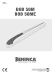
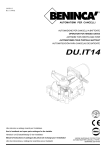
1
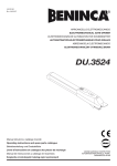
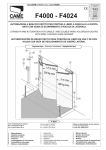
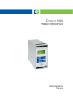
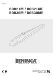
L8542474
12/2009 rev 1
DU.35V
UNIONE NAZIONALE COSTRUTTORI
AUTOMATISMI PER CANCELLI, PORTE
SERRANDE ED AFFINI
2
Dimensioni d’ingombro / Overall dimensions / Abmessungen
Dimensions d’encombrement / Dimensiones exteriores / Wymiary gabarytowe
* Corsa.
Stroke.
Hub.
Course.
Carrera.
Posuw.
350 *
354
820
92
136
1
Arresto in chiusura - indispensabile.
Stop when closing - essential.
Endanschlag zur Schließung - unerläßlich.
Arrêt en fermeture - indispensable.
Tope de cierre indispensable.
Zatrzymanie przy zamykaniu; obowiązkowo.
Arresto in apertura (necessario se non si usa il F. C.).
Stop when opening (necessary if not using the limit stop).
Endanschlag zur Öffnung (nötig, wenn kein Endschalter benutzt wird).
Arrêt en ouverture (arrêt en ouverture nécessaire si on n’utilise pas le F.C.).
Tope en apertura (necesario si no se usa el F.C.).
Zatrzymanie przy otwieraniu (konieczne, jeżeli nie używa się wyłącznika krańcowego)
3
2A
V
K
X
Z
Y
M
P
Apertura max.
Tempo apertura 90°
Max. opening
Opening time
Max. Öffnung
Öffnungszeit
X
Ouverture max.
Y
Abiertura max.
Z
min.
K
M*
max
Otwarcie maks.
Tiempo de abiertura
Czas otwierania
110°
105
110°
130
90°
165
105
130
165
70
90
110
585
50
560
530
75
100
* N.B.: La quota M max. è riferita ad una quota V= 50 mm
* N.B.: The dimension M max. refers to a dimension V= 50 mm
* N.B.: Das Maß M max. bezieht sich auf ein Maß V= 50 mm
* N.B.: La cote M max. est référée à une cote V= 50 mm
* N.B.: La cota M máx. hace referencia a la cota V= 50 mm
* N.B.: Wymiar M max odnosi się do parametru V = 50 mm
2B
U
4
Temps d’ouverture
13"
16"
21"
Dimensioni max. anta
Max. wing dimensions
Max Flügelmasse
Dimens. max. de la porte
Dimens. max. de la hoja
Maks. wymiary skrzydła
L (m)
P (kg)
2
300
2,5
200
2
400
2,5
300
3
200
3
300
S
P
3A
S
P
3B
Vite Ø3.9.
Screw Ø3.9.
Schraube Ø3.9.
Vis Ø3.9.
Tornillo Ø3.9.
Sruba Ø3.9.
R
M
V
S
P
P
U
F
D
Mettere a livello.
Level.
Nivellieren.
Mettre de niveau.
Nivelar.
Uliniować
T
S
5
4A
4B
F1
F1
COM
COM
C
F2
F2
C
F1
F2
C
4
5
6
COM
FCO
FCO
FCO
1
GND
F1
2
3
F2
COM
4
5
6
GND
1
2
3
4
1
F1
F2
COM
5
2
F1 FCOF2
6
3
4
5
GND FCO
COM
5
D
T
Posticipa.
Postpone.
Anziehen.
Diffère.
Atrasa.
Opóźnienie
Anticipa.
Advance.
Verlangsamt.
Anticipe.
Adelanta.
Wyprzedzenie
F.C. apertura
Opening limit stop
Öffnungsendschalter
Fin de course d’ouverture
F.C. apertura
Wył. krańc. otwierania
marrone: F.C. apre
brown: limit stop opens
brauner Draht: Endschalter richtung ”Tor-auf”
marron: le fin de course ouvre
marron: F.C. abrir
Brązowy: Wył- krańc. otwierania
blu: comune F.C.
blue: limit stop common
blauer Draht: gemeinsamer Erdung
bleu: fin de course commun
azul: comun F.C.
Granatowy: Wspólny wył. krańc.
F
6
6
GND
6
C
Spostare nel senso della freccia.
Move arrowise.
In Pfeilrichtung schieben.
Déplacer dans le sens de la flèche.
Desplazar en el sentido de la flecha.
Przesunąć w kierunku strzałki
Tirare.
Pull.
Ziehen.
Tirer.
Tirar.
Ciągnąć
Premere.
Press.
Drücken.
Pousser.
Presionar.
Wcisnąć
Inserire e ruotare di 90°.
Insert and rotate by 90°.
Einstecken und um 90° drehen.
Insérer et tourner de 90°.
Insertar y girar 90°.
Wprowadzić i obrócić o 90°.
P
Farla ruotare fino sentire lo scatto.
Rotate till the click.
Drehen, bis man es schnappen hört.
La faire tourner jusqu’à obtention du déclic.
Hacerla girar hasta sentir el golpecillo de desbloqueo.
Obracać aż do usłyszenia dźwięku wskazującego
zadziałanie urządzenia.
P
7
Collegamenti elettrici / Wire diagram / Elektrische Anschlüsse
Branchements électriques / Conexiones eléctricas / Połączenia elektryczne
4
5
0,3
2x
2x0,35
2x1,5
3
1
2x
2
1,5
4x
5
Legenda:
1 Motoriduttore DU.35V
2 Fotocellule SC.P50 (da incasso), SC.P50E (da esterno)
3 Selettore a chiave ID.SC o ID.SCE (da esterno) o tastiera digitale ID.PTD
4 Lampeggiante ID.LUX
5 Antenna LO.E1N (superreattiva) o LO.E1LUX (quarzata)
6 Centrale elettronica DA.93A
Legenda:
1 Motoreducer DU.35V
2 Photo-electric cells SC.P50 (built in), SC.P50E (external)
3 Key selector ID.SC or ID.SCE (external) or digital keyboard ID.PTD
4 Flash-light ID.LUX
5 Antenna LO.E1N (superreactive) or LO.E1LUX (quartz)
6 Electronic gearcase DA.93A
RG 58
1
1
1,5
1
2x
4x
5
0,3
2
4x
n
mi
1,5 c
3x 30Va
2
6
Zeichenerklärung:
1 Getriebemotor DU.35V
2 Fotozelle SC.P50 (eingelegt), SC.P50E (außenliegend)
3 Schlüssel-Selektor ID.SC oder ID.SCE (außenliegend) oder Digital-Tastatur ID.PTD
4 Blinker ID.LUX
5 Antennne LO.E1N (Superreaktiv) oder LO.E1LUX (Quartz)
6 Elektroschrank DA.93A
Légende:
1 Moteur-réducteur DU.35V
2 Photocellule SC.P50 (noyée) - SC.P50E (d’extérieur)
3 Selecteur à clé ID.SC ou ID.SCE (d’extérieur) ou clavier digital ID.PTD
4 Clignotant ID.LUX
5 Antenne LO.E1N (super-active) ou LO.E1LUX (au quartz)
6 Centrale électronique DA.93A
Leyenda:
1 Motorreductor DU.35V.
2 Fotocélulas SC.P50 (de empotrar), SC.P50E (de superficie).
3 Selectores a llave ID.SC o ID.SCE (de superficie).
4 Relampagueador ID.LUX.
5 Antena LO.E1N (superreactiva) o LO.E1LUX (cuarzada).
6 Central electrónica DA.93A.
Legenda:
1 Siłownik DU.35V
2 Fotokomórki SC.P50 (wbudowane), SC.P50E (zewnętrzne)
3 Wyłącznik kluczowy ID.SC lub ID.SCE (zewnętrzny) lub elektroniczna
tablica rzyciskowa ID.PTD
4 Lampa migocąca ID.LUX
5 Antena LO.E1N (superczuła) lub LO.E1LUX (kwarcowa )
6 Centralka elektroniczna DA.93A
8
N.B.: Tenere separati i cavi di potenza da quelli ausiliari.
N.B.: The power cables must be kept separated from
the auxiliary cables.
Wichtig: Leistungskabel von Hilfskabeln getrennt halten.
N.B.: Séparer les câbles de puissance des câbles
auxiliaires.
N.B.: Tener separados los cables de potencia de los
auxiliares.
Uwaga: należy trzymać w oddali przewody zasilania od
przewodów pomocniczych.
Dichiarazione CE di conformità per macchine
(Direttiva 98/37 CE, Allegato II, parte B) - Divieto di messa in servizio
Fabbricante: Automatismi Benincà SpA.
Indirizzo: Via Capitello, 45 - 36066 Sandrigo (VI) - Italia
Dichiara che: l’automazione per cancelli a battente modello DU.35V.
• è costruita per essere incorporata in una macchina o per essere assemblata con altri macchinari per costituire una macchina considerata dalla Direttiva 98/37 CE, come modificata;
• non è dunque conforme in tutti i punti alle disposizioni di questa Direttiva;
• è conforme alle condizioni delle seguenti altre Direttive CE:
Direttiva bassa tensione 73/23/CEE, 93/68/CEE.
Direttiva compatibilità elettromagnetica 89/336/CEE, 93/68/CEE.
e inoltre dichiara che non è consentito mettere in servizio il macchinario fino a che la macchina in cui sarà incorporata o di cui diverrà
componente sia stata identificata e ne sia stata dichiarata la conformità alle condizioni della Direttiva 98/37 CE e alla legislazione
nazionale che la traspone, vale a dire fino a che il macchinario di cui alla presente dichiarazione non formi un complesso unico con
la macchina finale.
Benincà Luigi, Responsabile legale.
Sandrigo, 08/04/2008.
AVVERTENZE
E' vietato l'utilizzo del prodotto per scopi o con modalità non previste nel presente manuale. Usi non corretti possono essere causa
di danni al prodotto e mettere in pericolo persone e cose.
Si declina ogni responsabilità dall'inosservanza della buona
tecnica nella costruzione dei cancelli, nonché dalle deformazioni
che potrebbero verificarsi durante l'uso.
Conservare questo manuale per futuri utilizzi.
L'installazione deve essere effettuata da personale qualificato
nel pieno rispetto delle normative vigenti.
I materiali dell'imballaggio non devono essere lasciati alla portata
dei bambini in quanto fonte di potenziale pericolo. Non disperdere
nell'ambiente i materiali di imballo, ma separare le varie tipologie
(es. cartone, polistirolo) e smaltirle secondo le normative locali.
L’installatore deve fornire tutte le informazioni relative al funzionamento automatico, manuale e di emergenza dell'automazione, e
consegnare all’utilizzatore dell’impianto le istruzioni d’uso.
•
Prevedere sulla rete di alimenta zione un interr u t to r e /s e z i o n a to r e o n n i p o l a r e c o n d i s t a n z a
d’apertura dei contatti uguale o superiore a 3 mm.
Verificare che a monte dell’impianto elettrico vi sia un interruttore differenziale e una protezione di sovracorrente adeguati.
Alcune tipologie di installazione richiedono il collegamento
dell'anta ad un impianto di messa a terra rispondente alle vigenti
norme di sicurezza.
Durante gli interventi di installazione, manutenzione e riparazione,
togliere l’alimentazione prima di accedere alle parti elettriche.
Le descrizioni e le illustrazioni presenti in questo manuale non
sono impegnative. Lasciando inalterate le caratteristiche essenziali del prodotto il fabbricante si riserva il diritto di apportare
qualsiasi modifica di carattere tecnico, costruttivo o commerciale
senza impegnarsi ad aggiornare la presente pubblicazione.
9
Introduzione
Ci congratuliamo con voi per aver scelto il motoriduttore
DU.35V.
Tutti gli articoli della vasta gamma Benincà sono il frutto di
una ventennale esperienza nel settore degli automatismi
e di una continua ricerca di nuovi materiali e di tecnologie
all’avanguardia.
Proprio per questo, oggi siamo in grado di offrire dei prodotti
estremamente affidabili che, grazie alla loro potenza, efficacia e durata, soddisfano pienamente le esigenze dell’utente
finale.
Tutti i nostri prodotti vengono costruiti in conformità alle
norme vigenti e sono coperti da garanzia.
Inoltre, una polizza R.C. prodotti stipulata con primaria compagnia assicurativa copre eventuali danni a cose o persone
causati da difetti di fabbricazione.
Notizie generali
Per un buon funzionamento delle automazioni in oggetto,
il cancello da automatizzare dovrà rispondere alle seguenti
caratteristiche:
- buona robustezza e rigidità
- le cerniere devono presentare giochi minimi e permettere
che le manovre manuali siano dolci e regolari
- in posizione di chiusura le ante devono combaciare fra loro
per tutta l’altezza.
F1
F2
COM
4. CABLAGGI
Apre
Chiude
Comune motore
Fig. 4A - Cablaggio standard - il finecorsa di apertura (FCO)
interrompe la fase motore.
Fig.4B - Per collegare il finecorsa di apertura (FCO) alla
centrale modificare i collegamenti come indicato.
5. Regolazione finecorsa
Per la regolazione del finecorsa in apertura procedere come
segue (fig.5):
• togliere il tappo T
• agire quindi sul dado D mediante una chiave esagonale a
tubo da 10mm; ruotarlo in senso orario per anticipare l’intervento del finecorsa F, viceversa per posticiparlo.
1. Caratteristiche generali
Semplice ed affidabile può essere installato su qualsiasi
cancello a battente fino a max. 3m per anta.
Armonico ed elegante è costruito interamente in alluminio.
Il gruppo di riduzione robusto e ben collaudato lo rende
affidabile e silenzioso. È inoltre dotato di finecorsa molto
semplici e pratici da regolare e di sblocco d’emergenza a
chiave personalizzata.
6. Sblocco e manovra manuale
Come gli altri automatismi della gamma Benincà, anche il
DU.35V è dotato di uno sblocco semplice e funzionale che
permette la manovra manuale in assenza di energia elettrica. Per sbloccare l’automatismo procedere come segue
(fig. 6):
• spostare il copriserratura C nel senso della freccia fino a
vedere quest’ultima.
• Inserire la chiave personalizzata e ruotarla di 90°.
• Premere sul lato posteriore della portina P ed, aiutandosi
poi tirandola dalla parte anteriore, farla ruotare fino a sentire
lo scatto.
Per ripristinare il funzionamento abbassare la portina; la
prima manovra ripristinerà il normale funzionamento.
N.B.: Se non si utilizza il finecorsa in apertura, è consigliabile
portare il cancello in posizione prossima alla chiusura prima
di ripristinare il funzionamento automatico.
2. Arresti meccanici
È indispensabile che il portone da automatizzare disponga
di un arresto meccanico in chiusura; l’arresto meccanico
diventa necessario anche in apertura quando non viene
utilizzato l’apposito F.C (fig. 1).
ATTENZIONE
La polizza RC prodotti, che risponde di eventuali danni a
cose o persone causati da difetti di fabbricazione, richiede
la conformità dell’impianto alla normativa vigente e l’utilizzo
di accessori originali Benincà.
3. Messa in posa dell’automatismo
3.1. Stabilire l’altezza dal suolo dell’automatismo (si consiglia il più centrato possibile rispetto al portone ed in corrispondenza di un solido traverso). Fissare quindi la piastra
P utilizzando le quattro viti M12 (in dotazione) rispettando
le quote di fig. 2A (potrebbe essere necessario cambiare la
posizione dello snodo posteriore U come in figura 2B).
3.2. Con il portone in chiusura, fissare la staffa S con due
viti M10 (in dotazione) allo stesso livello della piastra P ad
un traverso del portone o ad altro elemento adeguatamente
robusto; tener presente che in questa condizione il pistone
non deve essere totalmente a fine corsa (fig. 3A).
• Togliere quindi il riparo R ed il supporto morsettiera M
(fig. 3B).
• Inserire l’attuatore sul perno della staffa S.
• Inserire lo snodo posteriore U sulla piastra P ed inserirvi
il perno V.
• Bloccare quest’ultimo con il dado autobloccante D. Serrare
infine la vite T.
Nota: È possibile accedere con il cavo di alimentazione dalla
parte inferiore dell’automatismo tramite uno dei due fori ivi
predisposti; in questo caso usufruire del foro F sulla piastra
indicato in figura 3B e fare attenzione che l’automatismo si
fermi prima di tranciare il cavo.
10
Dati tecnici
Alimentazione
Potenza assorbita
Corrente assorbita
Spinta
Classe isolamento
Temper. funzionamento
Rumorosità
Condensatore
Lubrificazione
Corsa standard
Peso
DU.35V
230 Vac
310 W
1,4 A
2000 N
F
-20°C / +70°C
<70 dB
9 µF
Molykote Longterm 2 plus
350 mm
10 kg
EC Declaration of Conformity regarding machines
(Directive 98/37 CE, Annex II B) - No servicing
Manufacturer: Automatismi Benincà SpA.
Address: Via Capitello, 45 - 36066 Sandrigo (VI) - Italia
Herewith declares that: the operator for hinged gates model DU.35V.
• is intended to be incorporated into a machine or assembled together with other devices to form a machine in compliance with the
EC Directive 98/37, as amended;
• therefore, is not in every respect complying with this Directive;
• is complying with provisions set forth by the following other EC Directive:
EC Low voltage Directive (73/23/EEC, 93/68/EEC).
EC Directive of Electromagnetic Compatibility (89/336/EEC, 93/68/EEC)
Moreover, we herewith declare that the system shall not be put into service until the machine in which the same will be incorporated
or of which it will become a component, is acknowledged compliant with the EC Directive 98/37 and applicable national legislation
and a related declaration of conformity is drawn up. In other words, no servicing shall be carried out until the system under this
declaration does not form one single final machine with other components.
Benincà Luigi, Legal responsible.
Sandrigo, 08/04/2008.
WARNING
The product shall not be used for purposes or in ways other than
those for which the product is intended for and as described in
this manual. Incorrect uses can damage the product and cause
injuries and damages.
The company shall not be deemed responsible for the noncompliance with a good manufacture technique of gates as well
as for any deformation, which might occur during use.
Keep this manual for further use.
Qualified personnel, in compliance with regulations in force, shall
install the system.
Packaging must be kept out of reach of children, as it can be
hazardous. For disposal, packaging must be divided the various
types of waste (e.g. carton board, polystyrene) in compliance
with regulations in force.
The installer must supply all information on the automatic, manual
and emergency operation of the automatic system and supply
the end user with instructions for use.
•
An omnipolar switch/section switch with remote contact opening equal to, or higher than 3mm
must be provided on the power supply mains..
Make sure that before wiring an adequate differential switch and
an overcurrent protection is provided.
Pursuant to safety regulations in force, some types of installation
require that the gate connection be earthed.
During installation, maintenance and repair, cut off power supply
before accessing to live parts.
Descriptions and figures in this manual are not binding. While
leaving the essential characteristics of the product unchanged,
the manufacturer reserves the right to modify the same under the
technical, design or commercial point of view without necessarily
update this manual.
11
Introduction
Thank you for choosing our DU.35V ratiomotor.
All items in the wide Benincà production range are the result
of twenty-years’ experience in the automatism sector and
of continuous research for new materials and advanced
technologies.
We are, therefore, in the position to offer higly reliable products that due to their power, effectiveness and useful life,
fully satisfy the final user’s requirements.
All our products are manufactured to the existing standard
and are covered by warranty.
Possible injury to people or accidents caused by defects in
construction are covered by a civil liability policy drawn up
with one of the major insurance companies.
General information
For an efficient operation of these automatisms, the gate
must have the following features:
- good stoutness and stiffness
- all hinges must have positive clearances and permit smooth
and regular manual operations.
- when wings are closed their height have to fit together.
1. General features
The DU.35V electromechanical gate opener is simple and
reliable and can be installed onto any swing-gate having
up to 3m max wings. Harmonious and elegant it is made
entirely in aluminium.
The stout and well tested reduction unit makes it reliable
and noiseless. It is also equipped with simple and easily
adjustable limit stops and an emergency release with personalised key.
2. Mechanical stops
It is necessary that the gate to be automatised has got a mechanical stop when closing; this mechanical stop becomes
necessary also when opening in case the suitable limit stop
is not used (fig. 1).
3. Automatism positioning
3.1. Fix the distance from the ground of the automatism has
(it is advisable it is in the middle of the gate and possibly
close to a strong ledger). Fit the P plate by using the four M12
screws (supplied) according to measures shown in fig. 2A
(it might be required to change the position of the upper U
articulation, as per figure 2B).
3.2. With the door in the closing phase, fix the S bracket with
the M10 screws (supplied) at the same level of the P plate to
a beam of the man door or other adequately rugged element.
Keep in mind that, in this condition, the piston must not be
entirely in the end-stroke position (fig. 3A).
• Remove then the protection R and the terminal board
support M (fig. 3B).
• Insert the back articulated joint U onto the plate P and
insert the pivot V. Tighten the pivot through the self-blocking
nut D.
• Tighten now the screw T.
Note: the power supply cable can be introduced into the
lower part of the automatism, by means of one of the two
holes situated there. If this is the case, use the plate hole F
indicated in the figure 3B and make sure that the automatism
stops before cutting the cable.
12
F1
F2
COM
4. CONNECTIONS
Open
Close
Motor common wire
Fig. 4A – Standard wiring - the opening limit switch (FCO)
interrupts the motor phase.
Fig. 4B – To connect the opening limit switch (FCO) to the
control unit, modify the connections as indicated.
5. Limit stop adjustment
For the limit stop adjustment when opening, proceed as
follows (fig.5):
• remove cap T
• loosen nut D by means of a 10mm hexagon head socket
spanner; turn the nut clockwise to advance the triggering
of the limit switch F and anticlockwise to postpone triggering.
6. Release and manual move
As all the other automatisms in the Benincà production range,
also the DU.35V has a simple and functional release which
permits the manual move when there is no electricity. To
release the automatism, please proceed as follows (fig. 6):
• Move the lock-cover C until the arrow is visible.
• Insert the personalised key and rotate it by 90°.
• Press onto the back side of the door P and rotate it to a
click by pulling from the front side.
In order to make it run again, lower the small door; the first
manoeuvre will re-establish the manual operation.
P.N.: if the opening limit stop is not used, it is advisable to
bring the gate in a position close to the closing one before
re-establishing the automatic running.
CAUTION
The civil liability policy, which covers possible injuries to
people or accidents caused by defects in construction,
requires the system to be to existing standard and to use
original Benincà accessories.
Technical data
Power supply
Absorbed rating
Absorbed current
Thrust
Insulation class
Operating temperature
Noise level
Capacitor
Lubrication
Standard stroke
Weight
DU.35V
230 Vac
310 W
1,4 A
2000 N
F
-20°C / +70°C
<70 dB
9 µF
Molykote Longterm 2 plus
350 mm
10 kg
EG-Konformitätserklärung für Maschinen
(Richtlinie 98/37 EG, Anhang II, Teil B) – Inbetriebsetzen verboten
Hersteller: Automatismi Benincà SpA.
Adresse: Via Capitello, 45 - 36066 Sandrigo (VI) - Italia
Wir erklären, dass: Antriebe für Drehflügeltore DU.35V.
• hergestellt worden ist, um in Maschinen eingebaut oder in Verbindung mit anderen Maschinen verwendet zu werden, wodurch
die Maschine laut EG-Richtlinie 98/37 als umgeändert gilt;
• die Automation entspricht daher nicht allen Punkten der Vorschriften dieser Richtlinie;
• sie entspricht folgenden EG-Richtlinien:
Niederspannungs-Richtlinie 73/23/EWG, 93/68/EWG.
Richtlinie über die elektromagnetische Verträglichkeit 89/336/EWG, 93/68/EWG.
Wir erklären zudem, dass die Maschine/Anlage in welche oder in Verbindung mit welcher die Automation installiert wird, nicht in
Betrieb gesetzt werden darf, bis sie identifiziert und laut EG-Richtlinie 98/37 sowie laut den nationalen Gesetzen, die zur Umsetzung
der EG-Richtlinie erlassen wurden, als konform erklärt worden ist. Die hier genannte Automation muss daher mit der Maschine als
ein Ganzes als konform erklärt werden.
Benincà Luigi, Rechtsvertreter
Sandrigo, 08/04/2008.
HINWEISE
Das Produkt darf nicht für andere Zwecke oder auf andere Weise
verwendet werden, als in der vorliegenden Anleitung beschrieben.
Ein ungeeigneter Gebrauch kann das Produkt beschädigen und
eine Gefahr für Personen und Sachen darstellen.
Wir übernehmen keinerlei Haftung für Schäden, die sich aus einer
unsachgerechten Montage der Tore und aus daraus folgenden
Verformungen ergeben können.
Bewahren Sie dieses Handbuch für Nachschlagzwecke auf.
Die Installation darf nur von qualifizierten Fachleuten laut den
geltenden Vorschriften vorgenommen werden.
Das Verpackungsmaterial fern von Kindern halten, da es eine
potentielle Gefahr darstellt. Das Verpackungsmaterial nicht ins
Freie werfen, sondern je nach Sorte (z.B. Pappe, Polystyrol) und
laut den örtlich geltenden Vorschriften entsorgen.
Der Installateur hat dem Benutzer alle Informationen über den
automatischen, manuellen Betrieb sowie den Not-Betrieb der
Automatik zusammen mit der Bedienungsanleitung zu liefern.
•
Das Stromnetz muss mit einem allpoligen Schalter bzw.
Trennschalter ausgestattet sein, dessen Kontakte einen
Öffnungsabstand gleich oder größer als 3 aufweisen..
Kontrollieren, ob der elektrischen Anlage ein geeigneter Differentialschalter und ein Überspannungsschutzschalter vorgeschaltet sind.
Einige Installationstypologien verlangen den Anschluss des
Flügels an eine Erdungsanlage laut den geltenden Sicherheitsnormen.
Während der Installation, der Wartung und der Reparatur, die
Anlage stromlos machen bevor an den elektrischen Teilen gearbeitet wird.
Die in diesem Handbuch enthaltenen Beschreibungen und Abbildungen sind nicht verbindlich. Ausgenommen der Haupteigenschaften des Produkts, behält sich der Hersteller das Recht vor
eventuelle technische, konstruktive oder kommerzielle Änderungen vorzunehmen ohne dass er vorliegende Veröffentlichung auf
den letzten Stand bringen muss.
13
Einleitung
Wir danken Ihnen dafür, daß Sie sich für den DU.35V Gitteröffner entschieden haben.
Alle Produkte der umfangreichen Benincà Produktion sind
das Ergebnis der zwanzigjährigen Erfahrungen im Bereich
der Automation und der ständigen Erforschung von neuen
Materialien und fortgeschrittenen Technologien.
Aus diesem Grund sind wir heute in der Lage, zuverlässige
Produkte anzubieten, die, dank ihren Stärke, Wirksamkeit
und Haltbarkeit, der Anforderungen des Endverbrauchers
völlig gerecht werden.
Alle Produkte sind nach Normen gefertigt und durch Garantie
gedeckt.
Eventuelle Personen- oder Sachschäden, die durch Fertigungsfehler verursacht werden können, werden durch eine
der wichtigsten Versicherungsgesellschaften gedeckt.
Allgemeine Information
Zum guten Betrieb der genannten Automation, muß das
Gitter folgende Eigenschaften haben:
- Stärke und Festigkeit
- Die Scharniere müssen minimale Spiele aufweisen und
die manuelle Öffnung und Schließung müssen in jedem Fall
leicht sein.
- Bei der Schließung müssen die Flügel genau aufeinander
passen.
1. Allgemeine Eigenshaften
Der einfache und zuverlässige Automatismus kann an jedem
Flügeltor von höchstens 3m je Flügel angebracht werden. Er
hat eine harmonische und elegante Form und ist ganz aus
Aluminium gebaut.
Die starke und gut eingefahrene Untersetzungseinheit macht
ihn zuverlässig und leise. Außerdem ist er mit sehr einfachen
und praktisch regulierbaren Endschaltern und Notfreigabe
mit individuellem Schlüssel versehen.
2. Mechanische Endanschläge
Es ist unerläßlich, daß das zu automatisierende Tor einen
mechanischen Halt beim Schließen hat; dieser ist auch beim
Öffnen nötig, wenn der dazu bestimmte Endschalter nicht
benutzt wird (Bild 1).
3. Anbringung des Automatismus
3.1. Die Höhe des Automatismus über dem Fußboden bestimmen (möglichst auf die Mitte des Tores und auf einen
festen Querträger bezogen). Die Platte P mit Hilfe der vier
Schrauben M12 (mitgeliefert) befestigen. Die Maße in Abb.
2A berücksichtigen (ggf. könnte es sinnvoll sein, die Position
des hinteren Gelenks U, wie in Abbildung 2B zu ändern).
3.2. Wenn das Tor auf Schließen geschaltet ist, den Bügel
S mit zwei Schrauben M10 (mitgeliefert) auf dieselbe Höhe
der Platte P an eine robuste Stelle des Tors (z.B. Querträger)
befestigen. Beachten Sie bitte, dass der Kolben in dieser
Position nicht ganz bis zum Endanschlag gefahren sein darf
(siehe Abb. 3A).
• Dann nehme man den Handschutz R und den Klemmbretthalter M ab (Bild 3B).
• Den Trieb auf den Stift des Bügels S setzen. Das hintere
Gelenk U auf die Platte P setzen und den Stift V einfügen;
diesen mit der selbstsperrenden Mutter D sperren.
• Schließlich ziehen Sie Schraube T an.
Hinweis: Über eine der Öffnungen, die im unteren Teil des
Antriebs vorgesehen sind, kann das Versorgungskabel
zugeführt werden. In diesem Fall ist die in der Abbildung
3B gezeigte Öffnung F in der Platte zu verwenden. Hierbei
beachten, daß der Antrieb vor dem Kabel anhält, um eine
Schnittgefahr zu vermeiden.
14
4. Kabelanschlüsse
F1
F2
COM
Öffnet
Schliesst
Gemeinsame Motordraht
Abb. 4A - Standardverkabelung - der Endschalter für Öffnen
(FCO) unterbricht die Motorphase.
Abb. 4B – Um den Endschalter für Öffnen (FCO) an die
Zentrale anzuschließen, die Verbindungen wie angegeben
verändern.
5. Einstellung des Endschalters
Zur Einstellung des Endschalters beim Öffnen gehe man
folgendermaßen vor (Bild 5):
• Stopfen T abnehmen.
• Mit einem Sechskantsteckschlüssel zu 10mm die Mutter
D in den Uhrzeigersinn drehen, um das Einschalten des
Endschalters F vorzuverlegen oder gegen den Uhrzeigersinn
drehen, um das Einschalten zu verzögern.
6. Freigabe und Handbetrieb
Wie die anderen Automatismen von Benincà, ist DU.35V
mit einer einfachen und praktischen Freigabe versehen, die
Handbetrieb bei Stromausfall ermöglicht. Zur Freigabe des
Automatismus gehe man so vor (Bild 6):
• Schloßdeckel C in Pfeilrichtung schieben, bis der Pfeil
sichtbar wird.
• Den individuellen Schlüssel einstecken und um 90° drehen.
• Auf die Rückseite des Türchens P drücken, dieses nach
vorn ziehen und drehen, bis man es schnappen hört.
Zur Wiederaufnahme des Betriebes das Türchen senken. Die
erste Verschiebung stellt den normalen Betrieb wieder her.
Anmerkung: benutzt man den Endschalter nicht beim Öffnen,
sollte man das Tor nahezu in Schließstellung bringen, bevor
man den automatischen Betrieb wiederherstellt.
BITTE BEACHTEN
Die Versicherung deckt nur Personen- oder Sachschäden,
die durch Fertigungsfehler verursacht werden und gilt nur
bei Einsatz von Benincà Original-Ersatzteilen und wenn die
Anlage der Normen entspricht.
Technische Daten
Speisung
Leistung
Strom-Verbrauch
Druck
Isolierklasse
Laufzeit
Geräuschentwicklung
Kondensator
Schmierung
Standardhub
Gewicht
DU.35V
230 Vac
310 W
1,4 A
2000 N
F
-20°C / +70°C
<70 dB
9 µF
Molykote Longterm 2 plus
350 mm
10 kg
Déclaration CE de conformité pour machines
(Directive 98/37 CE, Annexe II, partie B) – Interdiction de mise en service
Fabricant: Automatismi Benincà SpA.
Adresse: Via Capitello, 45 - 36066 Sandrigo (VI) - Italia
Déclaire ci-apres que: l’automation pour portails ouvrants DU.35V.
• est conçu pour être incorporé dans une machine ou pour être assemblé avec d’autres machines à fin que le tout puisse constituer
une machine considérée par la Directive CE, comme modifiée;
• donc elle n’est pas conforme point pour point à tous les termes de cette Directive;
• elle satisfait les conditions des autres Directives CE ci-dessous:
Directive basse tension 73/23/CEE, 93/68/CEE.
Directive compatibilité électromagnétique 89/336/CEE, 93/68/CEE.
et de plus le fabricant déclare qu’il est formellement interdit de mettre en service l’appareillage jusqu’à ce que la machine dans
laquelle il sera incorporé ou dont il deviendra une partie composante, n’ait été identifiée et déclaré conforme à la Directive 98/37
CE et à sa transposition dans la législation nationale, c’est-à-dire jusqu’à ce que la machine dont à la présente déclaration ne forme
pas un complexe unique avec la machine finale.
Benincà Luigi, Responsable légal.
Sandrigo, 08/04/2008.
REGLES DE SECURITE’
Il est interdit d’utiliser ce produit pour l’utilisation du produit ou
avec des finalités ou modalités non prévues par le présent manuel.
Toute autre utilisation pourrait compromettre l’intégrité du produit
et présenter un danger pour les personnes ou pour les biens.
Le fabricant décline toute responsabilité en cas d’utilisation
impropre ou d’inobservation de la bonne technique dans la construction des portails, ainsi que de toute déformation qui pourrait
avoir lieu lors de son utilisation.
Toujours conserver la notice pour toute autre consultation future.
L’installation doit être faite uniquement par un personnel qualifié
dans le respect total des normes en vigueur.
Tenir à l’écart des enfants tous les matériaux d’emballage car ils
représentent une source potentielle de danger. Ne pas disperser
les matériaux d’emballage dans l’environnement, mais trier selon
les différentes typologies (i.e. carton, polystyrène) et les traiter
selon les normes locales.
L’installateur doit fournir toutes les informations relatives au
fonctionnement automatique, au déverrouillage d’urgence de
l’automatisme, et livrer à l’utilisateur les modes d’emploi.
•
Prévoir sur le réseau de l’alimentation un interrupteur / sectionneur omnipolaire avec distance d’ouverture des contacts égale ou supérieure à 3 mm..
Vérifier la présence en amont de l’installation électrique d’un
interrupteur différentiel et d’une protection de surcourant
adéquats.
Certains types d’installation requièrent le branchement du vantail à une installation de mise à terre satisfaisant les normes de
sécurité e vigueur.
Avant toute intervention, d’installation, réparation et maintien,
couper l’alimentation avant d’accéder aux parties électriques.
Les descriptions et les illustrations présentées dans ce manuel
ne sont pas contraignantes. En laissant inaltérées les caractéristiques essentielles du produit, le fabricant se réserve le droit d’apporter toute modification à caractère technique, de construction
ou commerciale sans s’engager à revoir la cette publication.
15
Introduction
Nous ne pouvons que féliciter d’avoir porté votre choix sur
le moto-réducteur DU.35V.
Vingt années d’expérience dans le secteur des automatismes
ainsi que dans le recherche de nouveaux matériaux et technologies de pointe, nous ont permis de développer tous les
nombreux articles de la gamme Benincà. Pour ces raisons,
nous sommes en mesure de proposer des produits extrémement fiables et qui grâce à leurs puissances, performances
et longévité, répondent aux exigences des utilisateurs.
Tous nos produits sont construits selon les normes en vigueur et sont garantis.
En plus, une police d’assurance responsabilité civile garantie
la couverture d’éventuels sinistres à personnes ou objects
causés par les défauts de fabrication.
Notice générales
Pour un bon fonctionnement de l’automatisme en object, la
porte basculante doit avoir les suivantes caractéristiques:
- bonne robustesse et rigidité
- les charniéres doivent avoir un moindre jeu pour permettre
que les manoeuvres soient aisées et réguliéres.
- en position de fermeture, les portes doivent parfaitement
coïncider entre elles et sur toute la hauteur.
1. Caractéristiques générales
Simple et fiable, il peut être installé sur tout type de portail à
battant de dimension maximum de 3m par porte. Harmonique et élégant, il est entièrement construit en aluminium.
Le groupe de réduction robuste et complètement testé le
rend fiable et silencieux. De plus il est équipé de fins de
course très simples et pratiques à régler et de déblocage
d’arrêt d’urgence à clé personnalisé.
2. Arrêts mécaniques
Il est indispensable que le portail à automatiser dispose d’un
arrêt mécanique en fermeture. L’arrêt mécanique devient
nécessaire aussi en ouverture quand le F.C. spécial n’est
pas utilisé (fig. 1).
3. Mise en place de l’automatisme
3.1. Établir la hauteur par rapport au sol de l’automatisme
(nous vous conseillons de la déterminer la plus centrée
possible par rapport au portail et en correspondance d’une
traverse solide). Fixer donc la platine P à l’aide des quatre
vis M12 (fournies) en respectant les côtes de la fig. 2A (Il
peut arriver de devoir changer la position de la charnière
postérieure U comme indiqué dans la figure 2B).
3.2. Avec le portail en fermeture, fixer la bride F avec deux vis
M10 (fournies) au même niveau de la platine P à une traverse
du portail ou à tout autre élément suffisamment solide; il faut
tenir compte que dans cette condition le piston ne doit pas
être totalement en fin de course (fig. 3A).
• Enlever donc la protection R et le support de la barrette
M (fig. 3B).
• Insérer le réalisateur sur la tige de la patte S.
• Insérer le joint à rotule postérieur U sur la plaque P et
insérer la tige V.
• Bloquer cette dernière avec l’écrou auto bloquant D.
• Serrer enfin la vis T.
Note: Il est possible d’accéder avec le câble d’alimentation
par la partie inférieure de l’automatisme au moyen de l’un
des deux trous spécialement prédisposés; dans ce cas, il
faut utiliser le trou F sur la plaque indiqué dans la figure 3B
et faire attention à ce que l’automatisme s’arrête avant de
couper le câble.
16
4. CONNEXIONS
F1
F2
COM
Ouvre
Ferme
Commun moteur
Fig. 4A – Câblage standard - le fin de course d’ouverture
(FCO) interrompt la phase moteur.
Fig. 4B – Pour connecter le fin de course d’ouverture (FCO)
à la logique de commande, modifier les connexions suivant
les indications.
5. Réglage du fin de course
Pour le réglage du fin de course en ouverture procéder
comme suit (fig. 5):
• Retirer le bouchon T;
• Intervenir ensuite sur l'écrou D à l'aide d'une clé à tube
hexagonale de 10mm; le tourner dans le sens des aiguilles
d'une montre pour anticiper l'intervention du fin de course
F et dans le sens contraire pour la différer.
6. Déblocage et manoeuvre manuelle
Comme pour les autres automatismes de la gamme Beninca,
le DU.35V est équipé d’un déblocage simple et fonctionnel
qui permet la manoeuvre manuelle en absence d’énergie
électrique.
Pour débloquer l’automatisme procéder comme suit (voir
fig. 6):
• déplacer le couvre serrure C dans le sens de la flèche
jusqu’à voir cette dernière.
• Insérer la clé personnalisée et la tourner de 90°.
• Pousser sur le côté postérieur de la porte P et en s’aidant
par la suite en la tirant du côté antérieur, la faire tourner
jusqu’à obtention du déclic.
Pour rétablir le fonctionnement, abaisser la porte. La première manoeuvre rétablira le fonctionnement normal.
N.B.: Si on n’utilise pas le fin de course en ouverture, il est
conseillé de mettre le portail dans une position proche de la
fermeture avant de rétablir le fonctionnement automatique.
ATTENTION
Pour que la police d’assurance R.C. réponde à d’eventuels
sinistres causés à choses ou personnes, en cas de défauts
de fabrication, il faut que le montage soit réalisé suivant les
normes en vigueur et que soient utilisés des accessoires
Benincà.
Donnees technique
Alimentation
Puissance absorbée
Courant absorbé
Poussée
Classe d'isolement
Température de fonct.
Bruit
Condensateur
Lubrification
Course standard
Poids
DU.35V
230 Vac
310 W
1,4 A
2000 N
F
-20°C / +70°C
<70 dB
9 µF
Molykote Longterm 2 plus
350 mm
10 kg
Declaración CE de conformidad para máquinas
(Directiva 98/37 CE, Anexo II, parte B) – Prohibición de puesta en servicio
Fabricante: Automatismi Benincà SpA.
Dirección: Via Capitello, 45 - 36066 Sandrigo (VI) - Italia
Declara que: la automatización para cancelas de batiente DU.35V.
• ha sido construida para ser incorporada en una máquina o para ser ensamblada con otras máquinas para formar una máquina
considerada por la Directiva 98/37 CE, como modificada;
• no es pues conforme en todos los puntos a las disposiciones de esta Directiva;
• cumple las condiciones de las siguientes otras Directivas CE:
Directiva baja tensión 73/23/CEE, 93/68/CEE.
Directiva compatibilidad electromagnética 89/336/CEE, 93/68/CEE.
y declara así mismo que no se permite poner en servicio la maquinaria hasta que la máquina en la cual vaya incorporada o de la cual
se vuelve un componente, haya sido identificada y haya sido declarada su conformidad a las condiciones de la Directiva 98/37 CE
y a la legislación nacional que la aplica, es decir hasta que la maquinaria objeto de la presente declaración no forme un conjunto
único con la máquina final.
Benincà Luigi, Responsable legal.
Sandrigo, 08/04/2008.
ADVERTENCIAS
Está prohibido utilizar el producto para finalidades o con modalidades no previstas en el presente manual. Usos incorrectos
pueden causar daños al producto y poner en peligro personas
y cosas.
Se rehúsa cualquier responsabilidad en caso de incumplimiento de la buena técnica en la construcción de las cancelas, así
como en cuanto a las deformaciones que pudieran producirse
durante el uso.
Guardar este manual para futuras consultas. La instalación debe
ser efectuada por personal cualificado respetando plenamente
las normas vigentes.
Los elementos del embalaje no se deben dejar al alcance de los
niños ya que son potenciales fuentes de peligro. No tirar al medio
ambiente los elementos del embalaje, sino que se deben separar
según los varios tipos (por ej. cartón, poliestireno) y evacuarlos
de conformidad con las normas locales.
El instalador debe proporcionar todas las informaciones relativas
al funcionamiento automático, manual y de emergencia de la
automatización y entregar al usuario del equipo las instrucciones
de uso.
•
Prever en la red de alimentación un interruptor/
cortacircuitos omnipolar con distancia de apertura de los contactos igual o mayor que 3 mm.
C o m p r o b a r q u e e n t r e e l a p a r a to y l a r e d e l é c t r i ca general haya un interruptor diferencial y una
protección contra sobrecorriente adecuados.
Algunos tipos de instalación requieren que se conecte la hoja
con una instalación de puesta a tierra conforme a las vigentes
normas de seguridad.
Durante las operaciones de instalación, mantenimiento y reparación, cortar la alimentación antes de acceder a las partes
eléctricas.
Las descripciones y las ilustraciones presentadas en este manual
no son vinculantes. Sin cambiar las características esenciales del
producto, el fabricante se reserva el derecho de aportar cualquier
modificación de carácter técnico, constructivo o comercial sin
obligación de actualizar la presente publicación.
17
Introduccion
Nos congratulamos con vd. por haber elegido el motorreductor DU.35V.
Todos los artículos de la vasta gama Benincà son el fruto de
una veinteañal experiencia en el sector de los automatismos
y de una contínua búsqueda de nuevos materiales y de
tecnología de vanguardia.
Precisamente por esto, hoy nos encontramos en situación
de poder ofrecer productos extremadamente fiables que,
gracias a su potencia, eficacia y duración, satisfacen plenamente las exigencias del usuario final. Todos nuestros
productos están construidos de conformidad con la norma
y están garantizados. Además, una póliza R.C. productos,
estipulada con una de las principales compañías de seguros,
cubre eventuales daños a personas o cosas causados por
defecto de fabricación.
Noticias generales
Para un buen funcionamiento de las automatizaciones en
cuestión, la cancela a automatizar deberá responder a las
siguientes características:
- Buena robustez y rigidez
- Las bisagras deben presentar un mínimo juego y permitir
que las maniobras manuales sean suaves y regulares.
- En posición cerrada las hojas deben quedar al mismo nivel
en altura.
1. Caracteristicas generales
Simple y fiable puede ser instalado sobre cualquier cancela
de batiente de hasta 3mts. por hoja.
Armónico y elegante está contruido totalmente en aluminio.
El grupo de reducción, robusto y bien comprobado, lo hace
fiable y silencioso. Está además provisto de finales de carrera muy simple y prácticos de regular y de desbloqueo de
emergencias con llave personalizada.
2. Topes mecanicos
Es indispensable que la puerta para automatizar disponga
de un tope mecánico en el cierre; el tope mecánico resulta
necesario también en apertura cuando no se utiliza el correspondiente F.C (fig. 1).
3. Posicionamiento del automatismo
3.1. Establecer la altura del suelo para el automatismo (se
aconseja lo más centrado posible con respecto a la puerta
y en correspondencia con un solido travesaño). Fijar seguidamente la placa P utilizando los cuatro tornillos M12
(suministrados) respetando las cotas indicadas en la fig. 2A
(podría ser necesario cambiar la posición de la articulación
trasera U como mostrado en la figura 2B).
3.2. Con la puerta en cierre, fijar el soporte S con dos tornillos M10 (suministrados), al mismo nivel que la placa P, en
un travesaño del puerta u otro elemento adecuadamente
robusto; tener presente que en esta condición el pistón no
tiene que estar completamente en final de carrera (fig. 3A).
• Quitar a continuación la tapa R y el soporte de bornes M
(fig. 3B).
• Insertar el operador sobre el perno de la placa S.
• Insertar la articulación posterior U sobre la placa P y pasarles el perno V.
• Blocar éste último con la tuerca autoblocante D.
• Atornillar finalmente el tornillo T.
Nota: es posible acceder con la manguera de alimentacion
a la parte inferior del automatismo mediante uno de los
agujeros predispuestos para ello; en este caso aprovechar el
agujero F de la placa indicado en la figura 3B y tener cuidade
que el automatismo se pare antes de corter la manguera.
18
F1
F2
COM
4. CONNEXIONS
Abrir
Cerrar
Común motor
Fig. 4A – Cableo estándar - el fin de carrera de apertura
(FCO) interrumpe la fase del motor.
Fig. 4B – Para conectar el fin de carrera de apertura (FCO)
a la central, modificar las conexiones como se indica.
5. Regulacion del final de carrera
Para la regulación del final de carrera en apertura proceder
como sigue (fig. 5):
• Quitar el tapón T.
• Actuar seguidamente sobre la tuerca D con una llave hexagonal de tubo de 10mm; girar la tuerca en sentido horario
para adelantar la actuación del final de carrera F, en sentido
antihorario para retrasarla.
6. Desbloqueo y maniobra manual
Como los demás automatismos de la gama Benincà el
DU.35V está provisto de un desbloqueo simple y funcional
que permite la maniobra manual en ausencia de energía
eléctrica. Para desbloquear el automatismo proceder como
sigue (fig.6):
• Desplazar el cubrecerradura C en el sintido de la flecha
hasta ver ésta última.
• Meter la llave personalizada y girarla 90.
• Presionar sobre el lado posterior de la puentecilla P y
ayudándose después tirar de la parte anterior, haciéndola
girar hasta sentir el golpecillo de desbloqueo.
Para restablecer el funcionamiento bajar la puentecilla; la
primera maniobra restablecerá el normal funcionamiento.
NOTA: Si no se utiliza el final de carrera en apertura, es
aconsejable poner la cancela en posición próxima al cierre
antes de restablecer el funcionamiento automático.
ATENCION
La póliza RC productos, que responde de eventuales daños
a personas o cosas causados por defectos de fabricación,
requiere la conformidad de la instalación según la normativa
y la utilización de accessorios originales Benincà.
Datos técnicos
Alimentación
Potencia absorbida
Corriente absorbida
Par
Clase de aislamiento
Temperatura funcionam.
Ruido
Condensador
Lubrificación
Carrera estancar
Peso
DU.35V
230 Vac
310 W
1,4 A
2000 N
F
-20°C / +70°C
<70 dB
9 µF
Molykote Longterm 2 plus
350 mm
10 kg
Deklaracja zgodności z normą CE dotyczącą maszyn
(Dyrektywa 98/37 CE, Załącznik II, część B) – Zakaz rozpoczęcia użytkowania
Producent: Automatismi Benincà SpA.
Adres: Via Capitello, 45 - 36066 Sandrigo (VI) - Italia
Oświadcza że: Automatyzm do bram uchylnych model DU.35V.
• zostało wyprodukowane celem przyłączenia go do maszyny lub zmontowania z innymi urządzeniami w celu stworzenia maszyny
pojmowanej tak, jak podaje Dyrektywa 98/37 CE, zaktualizowana;
• tak więc nie jest zgodne we wszystkich punktach z wymogami tej Dyrektywy;
• zgodne jest z wymogami innych, niżej podanych Dyrektyw CE:
Dyrektywa o niskim napięciu 73/23/CEE, 93/68/CEE
Dyrektywy o zgodności elektromagnetycznej 89/336/CEE, 93/68/CEE
i ponadto oświadcza, że zabrania się rozpoczęcia użytkowania wyposażenia maszynowego do chwili, kiedy maszyna, do której jest
ono włączone, lub którego będzie komponentem, zostanie zidentyfikowana i będzie posiadać oświadczenie zgodności z wymogami
Dyrektywy 98/37 CE i krajowych przepisów prawnych ujednoliconych ze wspomnianą Dyrektywą, to znaczy, do momentu, kiedy
wyposażenie maszynowe, którego dotyczy niniejsza deklaracja stanie się częścią składową maszyny w jej postaci końcowej.
Benincà Luigi, Odpowiedzialny za kwestie prawne.
Sandrigo, 08/04/2008.
OSTRZEŻENIA
Zabrania się używania produktu do celów i w sposób inny niż
przewidziane w niniejszym podręczniku. Nieprawidłowe używanie
może spowodować uszkodzenie produktu i stanowić zagrożenie
dla osób i rzeczy.
Nie bierze się na siebie żadnej odpowiedzialności za nieprzestrzeganie reguł dobrej techniki budowlanej przy realizacji bram,
a także w przypadku odkształceń, które mogłyby powstać w
trakcie użytkowania.
Przechowywać niniejszy podręcznik do przyszłego użytku.
Instalacja musi być wykonana przez wykwalifikowany personel z
zachowaniem wszelkich obowiązujących przepisów prawnych.
Nie można pozostawiać opakowania w miejscach dostępnych
dla dieci, ponieważ może to być niebezpieczne. Nie pozostawiać
opakowania w środowisku, tylko podzielić na poszczególne kategorie odpadów (n.p. karton, polistyrol) i zlikwidować je zgodnie
z obowiązującymi przepisami miejscowymi.
Instalator zobowiązany jest do udzielenia wszelkich informacji
dotyczących działania w trybie automatycznym, ręcznym i w
przypadku zaistnienia stanu alarmowego automatyzacji i wręczyć
użytkownikowi instalacji instrukcję użytkowania.
•
Należy przewidzieć w sieci wyłącznik/odłącznik sekcyjny wielobiegunowy, gdzie odległość rozwarcia
między stykami będzie równa lub większa 3 mm..
Sprawdzić, czy przed instalacją elektryczną jest odpowiedni
wyłącznik dyferencjalny i zabezpieczenie przed przetężeniem.
Niektóre typologie instalacji wymagają podłączenia skrzydła do uziemienia zgodnego z obowiązującymi normami bezpieczeństwa.
Podczas prac instalacyjnych, konserwacji i naprawy, przed
przystąpieniem do prac na częściach elektrycznych należy odciąć
zasilanie.
Opisy i ilustracje znajdujące się w niniejszym podręczniku podane są wyłącznie przykładowo. Pozostawiając niezmienione
istotne charakterystyki techniczne produktu, producent zastrzega sobie prawo do wprowadzania każdej zmiany o charakterze
technicznym, konstrukcyjnym lub handlowym, bez konieczności
modyfikowania niniejszej publikacji.
19
Wstęp
Gratulujemy Państwu wyboru siłownika DU.35V. Wszystkie
urządzenia szerokiej gamy produktów Benincà są wynikiem
dwudziestoletniego doświadczenia w sektorze automatyzacji
oraz ciągłych poszukiwań nowych materiałów i nowoczesnej
technologii. Właśnie dzięki temu jesteśmy w stanie oferować
produkty dające wysoki stopień zaufania, które dzięki swojej
mocy, skuteczności działania i trwałości są w stanie w pełni
zadowolić wymagania użytkownika.
Wszystkie nasze produkty wykonywane są zgodnie z przepisami obowiązujących norm i podlegają gwarancji.
Ponadto gwarantowane są dodatkowo przez polisę ubezpieczeniową odpowiedzialności cywilnej podpisaną z jedną ze
znanych firm ubezpieczeniowych, pokrywającą ewentualne
szkody na rzecz osób lub rzeczy wynikłe na skutek wad
fabrycznych.
Uwagi ogólne
W celu zapewnienia prawidłowego działania urządzenia
automatyzacji, brama, na której będzie zamontowane musi
odpowiadać niżej wymienionym parametrom:
- solidna i sztywna konstrukcja
- zawiasy muszą mieć odpowiedni luz pozwalający na
dokonanie manewru ręcznego w sposób regularny i nie
wymagający użycia siły
- w pozycji zamknięcia skrzydła bramy muszą przylegać do
siebie na całej ich długości.
1. Podstawowe parametry urządzenia
Urządzenie proste i skuteczne w działaniu, może być zainstalowane na jakiejkolwiek bramie skrzydłowej o szerokości
skrzydła maks. 3 m. Eleganckie, o zharmonizowanej formie,
wykonane całkowicie z aluminium. Zespół siłownika jest
solidny i sprawdzony w działaniu, co zapewnia jego skuteczność i cichą pracę. Wyposażony jest w wyłącznik krańcowy
o prostej konstrukcji i łatwej regulacji oraz w system odblokowania bezpieczeństwa na klucz osobisty.
2. Zatrzymanie mechaniczne
Konieczne jest, żeby brama, która ma być automatyzowana,
posiadała mechaniczne urządzenie zatrzymywania biegu w
fazie zamykania; takie samo mechaniczne urządzenie zatrzymywania konieczne jest w fazie otwierania, jeżeli nie jest
używany odpowiedni wyłącznik krańcowy (rys. 1).
3. Instalowanie urządzenia automatyzacji
3.1. W pierwszej kolejności należy ustalić na jakiej wysokości
od podłoża będzie zamontowane urządzenie automatyzacji
(sugeruje się pozycję możliwie najbardziej wycentrowaną
w stosunku do bramy, najlepiej na solidnej poprzecznicy).
Umocować płytę P za pomocą czterech śrub M12 (na wyposażeniu) przestrzegając nastaw z rys. 2A (może okazać
się konieczna zmiana pozycji tylnego przegubu U jak przedstawiono na rysunku 2B).
3.2. Przy drzwiach w trakcie zamykania, umocować wspornik
S dwoma śrubami M10 (na wyposażeniu) na tym samym
poziomie co płyta P do belki bramy lub do innego stosownie
wytrzymałego elementu; należy pamiętać o tym, że w tych
warunkach tłok nie powinien znajdować się całkowicie na
końcu toru (rys. 3A).
• Następnie należy odjąć osłonę R oraz obudowę skrzynki
zaciskowej (rys. 3B).
• Umocować siłownik na sworzniu wspornika S.
• Zamontować przegub tylny U na płycie P i wprowadzić
sworzeń V.
• Zamocować ten ostatni przy pomocy nakrętki samoblokującej D. Dokręcić śrubę T.
Uwaga: można wprowadzić przewód zasilania w dolnej
części urządzenia automatyzacji przeprowadzając go przez
jeden z wywierconych otworów; w tym przypadku należy
wykorzystać otwór F na płycie wskazany na rysunku 3B,
zwracając uwagę, żeby urządzenie zatrzymało się w sposób
uniemożliwiający przecięcie przewodu.
20
F1
F2
COM
4. Połączenia
Otwiera
Zamyka
Wspólny
Rys. 4A – Okablowanie standardowe – wyłącznik krańcowy
otwierania (FCO – Wył. kr. otw.) przerywa fazę silnika.
Rys. 4B - W celu połączenia wyłącznika krańcowego
otwierania (FCO) – Wył. kr. otw.) z centralką należy zmienić
połączenia tak jak to jest wskazane.
5. Regulowanie wyłącznika krańcowego
W celu wyregulowania wyłącznika krańcowego należy postępować tak jak podano poniżej (rys.5):
• zdjąć zaślepkę T
• następnie przy pomocy klucza rurowego sześciokątnego
10 mm należy obracać nakrętkę D, w kierunku zgodnym z
kierunkiem obrotu wskazówek zegara w celu wyprzedzenia
operacji zadziałania wyłącznika krańcowego lub w kierunku
odwrotnym w celu opóźnienia tej operacji.
6. Odblokowanie i manewr ręczny
Taka jak w przypadku innych urządzeń gamy produktów
Benincà, również DU.35V wyposażony jest w proste i
funkcjonalne urządzenie odblokowania, które pozwala na
dokonanie manewru ręcznego w przypadku wystąpienia
braku energii elektrycznej. W celu odblokownia urządzenia
automatyzacji należy postępować tak jak podano poniżej
(rys. 6).
• odchylić zaślepkę zamka C w kierunku strzałki aż do odsłonięcia zamka.
• Wprowadzić klucz osobisty i obrócić go o 90°.
• Nacisnąć tylną ścianę drzwiczek P, a następnie pociągając
je od strony przedniej obracać aż do usłyszenia dźwięku
oznaczającego zadziałanie mechanizmu.
W celu przywrócenia działania należy obniżyć drzwiczki –
pierwszy manewr przywróci normalne działanie urządzenia
automatyzacji.
N.B.: Jeżeli używany jest wyłącznik krańcowy otwierania,
przed przywróceniem działania automatycznego sugeruje
się ustawienie bramy w pozycji prawie zamkniętej.
UWAGA
Polisa odpowiedzialności cywilnej w odniesieniu do produktów, która pokrywa ewentualne koszty za szkody na rzecz
osób i rzeczy spowodowane wadami fabrycznymi wymaga,
żeby cała instalacja wykonana była zgodne z obowiązującymi normami oraz zastosowania oryginalnych akcesoriów
firmy Benincà.
Dane techniczne
Zasilanie
Natężemie
Pobór mocy
Skok
Klasa izolacji
Temperatura przy pracy
Max. halas
Kondensator
Smarowanie
Posuw standard
Ciężar
DU.35V
230 Vac
310 W
1,4 A
2000 N
F
-20°C / +70°C
<70 dB
9 µF
Molykote Longterm 2 plus
350 mm
10 kg
DU.35V
Libro istruzioni per l’utilizzatore - User’s handbook for the user
Handbuch für den Verbraucher - Manuel d’instructions pour l’utilisateur
Libro de instrucciones para el usuario - Instrukcja obsługi dla użytkownika
ITALIANO
Norme di sicurezza
• Non sostare nella zona di movimento delle ante.
• Non lasciare che i bambini giochino con i comandi o in prossimità delle ante.
• In caso di anomalie di funzionamento non tentare di riparare il guasto ma
avvertire un tecnico specializzato.
Manovra manuale e d’emergenza
In caso di mancanza dell’energia elettrica o di guasto, per azionare manualmente
le ante procedere come segue (riferirsi alle figure 7,8,9):
• spostare il copriserratura C nel senso della freccia fino a vedere quest’ultima.
• Inserire la chiave personalizzata e ruotarla di 90°.
• Premere sul lato posteriore della portina P ed, aiutandosi poi tirandola dalla
parte anteriore, farla ruotare fino a sentire lo scatto.
Per ripristinare il funzionamento abbassare la portina; la prima manovra ripristinerà il normale funzionamento.
N.B.: Se non si utilizza il finecorsa in apertura, è consigliabile portare il cancello in posizione prossima alla chiusura prima di ripristinare il funzionamento
automatico.
Manutenzione
• Controllare periodicamente l’efficienza dello sblocco manuale di emergenza.
• Astenersi assolutamente dal tentativo di effettuare riparazioni, potreste incorrere
in incidenti; per queste operazioni contattare un tecnico specializzato.
• L’attuatore non richiede manutenzioni ordinarie, tuttavia è necessario verificare
periodicamente l’efficienza dei dispositivi di sicurezza e le altre parti dell’impianto
che potrebbero creare pericoli in seguito ad usura.
Smaltimento
Qualora il prodotto venga posto fuori servizio, è necessario seguire le disposizioni
legislative in vigore al momento per quanto riguarda lo smaltimento differenziato
ed il riciclaggio dei vari componenti (metalli, plastiche, cavi elettrici, ecc.); è
consigliabile contattare il vostro installatore o una ditta specializzata ed abilitata
allo scopo.
Attenzione
Tutti i prodotti Benincà sono coperti da polizza assicurativa che risponde di eventuali danni a cose o persone causati da difetti di fabbricazione, richiede però la
marcatura CE della ”macchina” e l’utilizzo di componenti originali Benincà.
7
C
8
Tirare.
Pull.
Ziehen.
Tirer.
Tirar.
Ciągnąć
Premere.
Press.
Drücken.
Pousser.
Presionar.
Wcisnąć
ENGLISH
Safety rules
• Do not stand in the movement area of the gate.
• Do not let children play with controls and near the gate.
• Should operating faults occur, do not attempt to repair the fault but call a
qualified technician.
Manual and emergency manoeuvre
In the event of a power cut or breakdown, proceed as follows to operate the
wings manually (refer to figures 7,8,9):
• Move the lock-cover C until the arrow is visible.
• Insert the personalised key and rotate it by 90°.
• Press onto the back side of the door P and rotate it to a click by pulling from
the front side.
In order to make it run again, lower the small door; the first manoeuvre will reestablish the manual operation.
P.N.: if the opening limit stop is not used, it is advisable to bring the gate in a
position close to the closing one before re-establishing the automatic running.
Maintenance
• Every month check the good operation of the emergency manual release.
• It is mandatory not to carry out extraordinary maintenance or repairs as
accidents may be caused. These operations must be carried out by qualified
personnel only.
• The operator is maintenance free but it is necessary to check periodically if
the safety devices and the other components of the automation system work
properly. Wear and tear of some components could cause dangers.
Waste disposal
If the product must be dismantled, it must be disposed according to regulations
in force regarding the differentiated waste disposal and the recycling of components (metals, plastics, electric cables, etc..). For this operation it is advisable
to call your installer or a specialised company.
Warning
All Benincá products are covered by insurance policy for any possible damages
to objects and persons caused by construction faults under condition that the
entire system be marked CE and only Benincá parts be used.
P
9
P
21
DEUTSCH
Sicherheitsvorschriften
• Nicht im Öffnungsbereich verweilen.
• Kinder nicht mit den Steuerungen oder in der Nähe des Tores spielen lassen.
• Bei Funktionsausfällen nicht versuchen, den Schaden selber zu beheben,
sondern den Techniker rufen.
Manuelle Bedienung und Notbetrieb
Um das Tor im Falle eines Stromausfalls oder einer Betriebsstörung von Hand
betätigen zu können, die Entriegelung wie folgt einsetzen (siehe Abbildungen
7,8,9):
• Schloßdeckel C in Pfeilrichtung schieben, bis der Pfeil sichtbar wird.
• Den individuellen Schlüssel einstecken und um 90° drehen.
• Auf die Rückseite des Türchens P drücken, dieses nach vorn ziehen und
drehen, bis man es schnappen hört.
Zur Wiederaufnahme des Betriebes das Türchen senken. Die erste Verschiebung
stellt den normalen Betrieb wieder her.
Anmerkung: benutzt man den Endschalter nicht beim Öffnen, sollte man das
Tor nahezu in Schließstellung bringen, bevor man den automatischen Betrieb
wiederherstellt.
Wartung
• Monatliche Kontrolle der manuellen Notentriegelung
• Es ist absolut untersagt, selbstständig Sonderwartung oder Reparaturen vorzunehmen, da Unfälle die Folge sein können; wenden Sie sich an den Techniker.
• Der Antrieb braucht keine ordentliche Unterhaltung aber es ist periodisch notwendig die Leistungsfähigkeit der Sicherheitsvorrichtungen und die andere Teile
des Anlages zu prüfen. Sie könnten durch Abnutzung Gefaht hervorbringen.
Entsorgung
Wird das Gerät außer Betrieb gesetzt, müssen die gültigen Gesetzesvorschriften
zur differenzierten Entsorgung und Wiederverwendung der Einzelkomponenten,
wie Metall, Plastik, Elektrokabel, usw., beachtet werden. Rufen Sie Ihren Installateur oder eine Entsorgungsfirma.
Achtung
Alle Produkte BENINCA’ wurden mit einem Versicherungsschein versehen,
der alle eventuellen Schäden an Dingen oder Personen abdeckt, die durch
Herstellungsdefekte hervorgerufen wurden, vorausgesetzt, das Gerät besitzt
die Kennzeichnung EU und es wurden original BENINCA’ Einzelkomponenten
verwendet.
FRANÇAIS
Normes de sécurité
• Ne vous arrêtez jamais dans la zone de mouvement des portes.
• Ne laissez pas les enfants jouer avec les commandes ou à proximité des
portes.
• En cas d’anomalies de fonctionnement, n’essayez pas de réparer la panne
mais contactez un technicien spécialisé.
Manœuvre manuelle et d’urgence
En cas de coupure de courant ou de panne, pour actionner manuellement les
vantaux, procéder de la façon suivante (se référer aux figures 7,8,9):
• déplacer le couvre serrure C dans le sens de la flèche jusqu’à voir cette
dernière.
• Insérer la clé personnalisée et la tourner de 90°.
• Pousser sur le côté postérieur de la porte P et en s’aidant par la suite en la
tirant du côté antérieur, la faire tourner jusqu’à obtention du déclic.
Pour rétablir le fonctionnement, abaisser la porte. La première manoeuvre
rétablira le fonctionnement normal.
N.B.: Si on n’utilise pas le fin de course en ouverture, il est conseillé de mettre
le portail dans une position proche de la fermeture avant de rétablir le fonctionnement automatique.
Maintenance
• Contrôler tous les mois le bon état du déverrouilleur manuel d’urgence.
• S’abstenir impérativement de toute tentative d’effectuer des maintenances
extraordinaires ou des réparations, sous risque d’accident. Contactez un technicien spécialisé pour ces opérations.
• L’actuateur ne demande pas de manutention ordinaire mais il faut verifier
periodiquement l’efficience des dispositifs de sécurité et les autres parties de
l’installation qui puissent créer dangers à cause d’usure.
Démolition
Au cas où le produit serait mis hors service, il est impératif de se conformer aux
lois en vigueur pour ce qui concerne l’élimination différenciée et le recyclage des
différents composants (métaux, matières plastiques câbles électriques, etc...)
contactez votre installateur ou une firme spécialisée autorisée à cet effet.
Attention
Tous les produits Benincà sont couverts par une police d’assurance qui répond
d’éventuels préjudices corporels ou matériels provoqués à cause de défauts
de fabrication, mais qui requiert toutefois le marquage CE de la “machine” et
l’utilisation de pièces de rechange d’origine Benincà.
22
ESPAŇOL
Normas de seguridad
• No pararse en la zona de movimiento de las hojas.
• No dejar que los niños jueguen con los mando o en proximidad de las hojas.
• En caso de anomalías de funcionamiento no intentar reparar la avería sino
que avisar a un técnico especializado.
Maniobra manual y de emergencia
De fallar el suministro de energía eléctrica o en caso de avería y para accionar
manualmente las puertas, hay que hacer lo siguiente (tener como referencia
las figuras7,8,9):
• Desplazar el cubrecerradura C en el sintido de la flecha hasta ver ésta última.
• Meter la llave personalizada y girarla 90.
• Presionar sobre el lado posterior de la puentecilla P y ayudándose después tirar
de la parte anterior, haciéndola girar hasta sentir el golpecillo de desbloqueo.
Para restablecer el funcionamiento bajar la puentecilla; la primera maniobra
restablecerá el normal funcionamiento.
NOTA: Si no se utiliza el final de carrera en apertura, es aconsejable poner la
cancela en posición próxima al cierre antes de restablecer el funcionamiento
automático.
Mantenimiento
• Controlar periódicamente la eficiencia del desbloqueo manual de emergencia.
• Abstenerse absolutamente de intentar efectuar reparaciones, podrían incurrir
en accidentes; para estas operaciones contactar con un técnico especializado.
• El operador no requiere mantenimiento habitual, no obstante es necesario
verificar periódicamente la eficiencia de los dispositivos de seguridad y las otras
partes de la instalación que pudiesen crear peligros a causa del desgaste.
Eliminación de aguas sucias
Cada vez que el producto esté fuera de servicio, es necesario seguir las disposiciones legislativas en vigor en ese momento en cuanto concierne a la eliminación
de suciedad y al reciclaje de varios componentes (metales, plásticos, cables
eléctricos, etc.), es aconsejable contactar con su instalador o con una empresa
especializada y habilitada para tal fin.
Atención
Todos los productos Benincà están cubiertos por una póliza de seguros que
responde de eventuales daños a personas o cosas, causados por defectos de
fabricación, requiere sin embargo la marca CE de la ”máquina” y la utilización
de componentes originales Benincà.
POLSKY
Normy bezpieczeństwa
• Starać się nie przebywać w obszarze posuwu skrzydeł.
• Niedopuścić aby dzieci bawiły się sterownikami lub w pobliżu skrzydeł bramy.
• W przypadku niewłaściwego funkcjonowania nie starać się samemu dokonywać naprawy a powiadomić o fakcie technika wyspecjalizowanego.
Sterowanie ręczne i awaryjne
W przypadku braku dopływu energii elektrycznej podczas awarii, dla ręcznego
sterowania skrzydeł bramy należy postępować według poniższych wskazówek
(opierać się na przykładach podanych na rysunkach 7,8,9):
• odchylić zaślepkę zamka C w kierunku strzałki aż do odsłonięcia zamka.
• Wprowadzić klucz osobisty i obrócić go o 90°.
• Nacisnąć tylną ścianę drzwiczek P, a następnie pociągając je od strony przedniej
obracać aż do usłyszenia dźwięku oznaczającego zadziałanie mechanizmu.
W celu przywrócenia działania należy obniżyć drzwiczki – pierwszy manewr
przywróci normalne działanie urządzenia automatyzacji.
N.B.: Jeżeli używany jest wyłącznik krańcowy otwierania, przed przywróceniem
działania automatycznego sugeruje się ustawienie bramy w pozycji prawie
zamkniętej.
Konserwacja
• Sprawdzać okresowo sprawność działania ręcznego mechanizmu odblokowującego i bezpieczeństwa.
• Nie starać się w żadnym wypadku dokonywać napraw samemu z racji na
możliwość ulegnięcia wypadkowi, w celu naprawy należy skontaktować się z
technikiem wyspecjalizowanym.
• Siłownik nie wymaga normalnej konserwacji, tym niemniej wskazane jest
okresowe sprawdzanie sprawnoścsi działania elementów bezpieczeństwa i
pozostałych części instalacji, mogących stanowić zagrożenie z racji na stan
zużycia.
Eliminacja i demolowanie
W przypadku gdy urządzenie nie nadaje się już do dalszego użytkowania, w celu
pozbycia się go należy ściśle przestrzegać obowiązujących w danym momencie
norm prawnych regulujących zróżnicowany rozkład na części i odzyskiwanie
niektórych elementów składowych (metale, plastyk, kable elektryczne, itp.);
wskazane jest skontaktowanie się z instalatorem lub wyspecjalizowaną firmą,
autoryzowaną do tego rodzaju prac.
Uwaga
Wszystkie produkty Benincà objęte są polisą ubezpieczeniową na pokrycie szkód
poniesionych przez rzeczy lub osoby w wyniku wad produkcyjnych, pod warunkiem że urządzenia posiadają oznakowanie CE i oryginalne części Benincà.
2
1
5
6
8
7
3
4
DU.35V
Pos.
Denominazione - Description - Bezeichnung - Dénomination - Denominación - Określenie
Cod.
1
Finecorsa
Limit stop
Endschalter
Fin de course
Final de carrera
Krańcówka
9686058
2
Leva di sblocco
Release lever
Hebel
Levier
Pal. de desbloq.
Dźwigienka
9686054
3
Blister
Blister
Blister
Blister
Blister
Blister
9686076
4
Motore
Motor
Motor
Moteur
Motor
Silnik
9686392
5
Tubo alluminio
Guide
Führung
Guide
Guía aluminio
Rura
9686057
6
Supporto
Support
Stütze
Support
Soporte
Zaczep
9686052
7
Vite senza fine
Screw
Schraube
Vis sans fin
Tornillo sin fin
Śruba dwustronna
9686050
8
Ingranaggio
Release gear
Zahnrad
Engrenage
Engranaje
Koło zębate
9686391
23
AUTOMATISMI BENINCÀ SpA - Via Capitello, 45 - 36066 Sandrigo (VI) - Tel. 0444 751030 r.a. - Fax 0444 759728
24