1
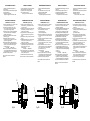
FORMA B2 - (SAE) (monosupporto)
1) Rimuovere le fascette B che bloccano il rotore
2) Togliere la rete R di protezione della flangia
dell'alternatore
3) Calettare la flangia F del generatore a quella
del motore, centrando nello stesso tempo i fori
del disco del giunto alternatore G con quelli
della sede volano del motore
4) Fissare la flangia alternatore al motore (coppia
di serraggio 30Nm)
5) Fissare il giunto alternatore al volano,
accedendo dalle aperture della flangia
6) Rimontare la rete di protezione
B2 FORM (SAE) (single beairing)
1) Retirez les colliers de serrage B du rotor
2) Retirez la grille R qui protège la bride de
l'alternateur
3) Emboîtez la bride F du générateur sur celle
du moteur, tout en centrant les trous du
disque du joint G de l'alternateur sur ceux du
logement du volant du moteur
4) Fixez la bride de l'alternateur au moteur
(couple de serrage 30Nm)
5) Fixez le joint de l'alternateur au volant, en
passant par les ouvertures de la bride
6) Remontez la grille de protection
F
fig.2A
fig.2B
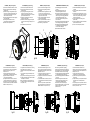
FORMA B3/B14 (bi-supporto)
B3/B14 FORM (double bearing)
si raccomanda di realizzare l'allineamento con
cura, verificando che lo scarto di concentricità e
parallelismo dei due semi-giunti non sia
superiore a 0.1mm.
1) Applicare all'alternatore il semigiunto di
accoppiamento e la campana di allineamento
2) Applicare all'albero del motore l'altro
semigiunto di accoppiamento
3) Accoppiare alternatore e motore, fissando la
campana di allineamento con le apposite viti
Verificare che per il cuscinetto posteriore esista
uno spazio sufficiente a permettere la dilatazione
assiale del rotore (almeno 1mm)
the alignment must be made with care, checking
that the difference in concentricity and
parallelism of the two half joints does not exceed
0.1mm
1) Apply the half-coupling and the adapter to the
alternator
2) Apply the other half-coupling to the motor shaft
3) Couple the alternator and the motor and fasten
the adapter with the screws
Make sure that there is sufficient space for the
rear bearing to permit the axial expansion of the
rotor (at least 1 mm)
fig.3A
1) Des Befestigungsbanden B des Läufers
entfernen
2) Das Schutznetz R am Flansch des
Wechselstromgenerators entfernen
3) Den Flansch F des Stromerzeugers auf den
des Motors aufziehen und dabei gleichzeitig
die Bohrungen an der Kupplungsscheibe G
des Wechselstromgenerators zu den
Bohrungen im Sitz des Schwungrads am
Motor ausrichten
4) Den Flansch des Wechselstromgenerators am
Motor befestigen (Anzugsmoment 30Nm)
5) Die Kupplung des Wechselstromgenerators
am Schwungrad durch die Öffnungen im
Flansch hindurch befestigen
6) Das Schutznetz wieder einsetzen
FORMA B2 - (SAE) (mono-soporte)
1) Quitar las abrazaderas B que bloquen el rotor
a la brida
2) Sacar la rejilla de protección R de la brida del
alternador
3) Ensamblar la brida del generador F con la del
motor, centrando al mismo tiempo los agujeros
del disco de la junta alternador g con los del
asiento volante del motor
4) Fijar la brida alternador al motor (par de
apriete 30Nm)
5) Fijar la junta alternador al volante, accediendo
por las aberturas de la brida
6) Volver a montar la rejilla de protección
G
R
B
FORM EINZELAUFHÄNGUNG B2 - (SAE)
FORME B2 - (SAE) (mono-palier)
1) Remove the clamps B that block the rotor
2) Remove the R protection screen from the
alternator flange
3) Key the F generator flange onto the motor
flange while lining up the holes in the G
alternator coupling disk with those in the motor
flywheel seat at the same time
4) Fasten the alternator flange to the motor
(tightening torque 30Nm)
5) Fasten the alternator coupling to the flywheel
by gaining access through the openings in the
flange
6) Re-assemble the protection screen
fig.2C
FORME B3/B14 (bi-palier)
il est conseillé d'effectuer l'alignement avec
soin, en vérifiant que l'écart de concentricité et
de parallélisme des deux semi-joints ne résulte
pas supérieur à 0.1mm.
1) Appliquez sur l'alternateur le demi-joint de
couplage et la cloche d'alignement
2) Appliquez à l'arbre du moteur l'autre demi-joint
de couplage
3) Couplez l'alternateur et le moteur, en fixant la
cloche d'alignement à l'aide des vis prévues à
cet effet
Assurez-vous qu'il existe un espace suffisant
pour le palier postérieur afin de permettre la
dilatation axiale du rotor (au moins 1 mm)
fig.3B
FORM B3/B14 (doppeltes Lager)
Die Ausrichtung ist besonders sorgfältig
durchzuführen. Entsprechend ist zu überprüfen,
dass die Abweichung von der Konzentrizität und
der Parallelität nicht mehr als 0,1mm beträgt.
1) Die Kupplungshälfte und die Kupplungsglocke
am Wechselstromgenerator anbringen
2) Die andere Kupplungshälfte an der Motorwelle
anbringen
3) Wechselstromgenerator und Motor durch
Befestigen der Kupplungsglocke mit den
entsprechenden Schauben koppeln
Sicherstellen, dass für das hintere Lager
ausreichend Platz vorhanden ist, um eine axiale
Ausdehnung des Läufers zu gestatten
(mindestens 1mm)
fig.3C
FORMA B3/B14 (bi-soporte)
se recomienda efectuar la alineación con
cuidado, verificar que el error de concentricidad
y paralelismo de los dos semi-acoplamientos no
sea superior a 0,1mm
1) Aplicar al alternador la semijunta de
acoplamiento y la campana de alineación
2) Aplicar la otra semijunta de acoplamiento al
eje del motor
3) Acoplar alternador y motor, fijando la campana
de alineación con los correspondientes
tornillos
Comprobar que para el cojinete trasero exista un
espacio suficiente que permita la dilatación axial
del rotor (como mínimo 1 mm)