1
GENERAL WARNINGS
ACCORGIMENTI GENERALI
-
-
Verificare la compatibilità dei dispositivi di
accoppiamento
Nel caso sia necessario sfilare il rotore,
ricordarsi prima di sollevare le spazzole, onde
evitare il loro danneggiamento
fissare l'alternatore al telaio utilizzando supporti
antivibranti adeguati
Verificare che il posizionamento delle spazzole
sia ben centrato sugli anelli del collettore
collegamenti in morsettiera:
coppia di serraggio: M6 - 5Nm / M8 - 8Nm
RÉNSEÍGNEMENTS GÉNERALES
Check the compatibility of the coupling devices
if it is necessary to withdraw the rotor, please lift
the brushes in order to avoid damaging
- fasten the alternator to the frame using
appropriate vibration-damping supports
- Always check to make sure that the brushes
are suitably centred on the slip rings
- terminal board connections:
coupling torque: M6 - 5Nm / M8 - 8Nm
-
-
-
Vérifiez la compatibilité des dispositifs de
couplage
au cas oú il serait nécessaire d' enlever le rotor
il faut éxécuter l' operation aprés avoir soulevé
les balais pour éviter de les endommager
fixez l'alternateur au cadre au moyen des
supports antivibrants adéquate
Assurez-vous toujours que le positionnement des
brosses est centré sur les anneaux du collecteur
branchements sur bornier:
couple de serrage: M6 - 5Nm / M8 - 8Nm
GENERELLE HINWEISE
-
-
ADVERTENCIAS GENERALES
Die Kompatibilität der Kopplungsvorrichtungen
überprüfen
Falls es notwendig ist, den Rotor zu
verschieben, sind zur Ver-hinderung von
Beschädigungen die Bürsten anzuheben.
den Wechselstromgenerator mit Hilfe von
Schwingmetallen am Rahmen befestigen
Stets überprüfen, dass die Bürsten mittig an
den Ringen des Schleifrings ausgerichtet sind
Anschlüsse am Klemmenblock:
Anzugsmoment: M6 - 5Nm / M8 - 8Nm
-
-
Comprobar la compatibilidad de los dispositivos
de acoplamiento
en el caso de que sea necesario sacar el rotor,
acordarse antes de levantar las escobillas, con
el fin de evitar su dañado
fijar el alternador al bastidor utilizando soportes
antivibrantes adecuados
Comprobar que la posición de las escobillas
esté bien centrada en los anillos del colector
conexiones en bornera:
par de cierre: M6 - 5Nm / M8 - 8Nm
ISTRUZIONE DI MONTAGGIO
ASSEMBLING INSTRUCTIONS
OPERATION DE MONTAGE
MONTAGEANLEITUNG
FORMA B3/B9 (mono-supporto)
B3/B9 FORM (single bearing)
FORME B3/B9 (mono palier)
FORM EINZELAUFHÄNGUNG B3/B9
FORMA B3/B9 (mono-soporte)
1) Retirez le protecteur postérieur C, et dévissez
les 4 écrous D1 qui bloquent les tirants
externes T1
2) Fixez la flasque antérieure S (les tirants
externes étant vissés) au moteur
d'entraînement (fig.1A)
(couple de serrage: 30Nm)
3) Monter la tige centrale T pour la fixation axiale,
la vissant a fond sur le bout d`arbre du moteur
(fig.1B).
4) Repositionnez le groupe carcasse et la flasque
postérieure (fig.1C)
5) Réassemblez l'alternateur en revissant aux
tirants les 4 écrous visés au point 1 (couple de
serrage de 30Nm).
6) Bloquer axialement le rotor, en utilisant le
rondelle et vissant a fond l`écrou autobloquant
D sur la tige centrale T en utilisant la clef
dynamometrique (fig.1C)
Couple de serrage:
C30: 40Nm - J609B: 25Nm
Attention: avant de mettre l`écrou, controler que
la partie fileteé de la tige centrale entre dans le
rotor, permettant ainsi un bloquage fermé.
7) Remontez le protecteur postérieur C
1) Die hintere Abdeckplatte C entfernen und die 4
Muttern D1 lösen, mit denen das äußere
Gestänge T1 befestigt ist
2) Mit angeschraubtem äußerem Gestänge, das
vordere Lagerschild S am Antriebsmotor
befestigen (fig.1A) (Anzugsmoment: 30Nm)
3) Die Zugstange T für die Achsbefestigung des
Rotors durch vollständiges Einschrauben auf dem
Überstand der Motorwelle anbringen (fig.1B).
4) Die Gehäuseeinheit und das hintere
Lagerschild (fig.1C) erneut platzieren
5) Den Wechselstromgenerator erneut
zusammensetzen und dazu die 4 Muttern laut
Punkt 1 wieder am Gestänge festschrauben
(Anzugsmoment 30Nm).
6) Den Rotor in Achsenrichtung blockieren, indem
die Unterlegscheiben angebracht und die
selbstsperrende Mutter D auf der Zugstange T
mit einem Drehmomentenschlüssel angezogen
wird (fig.1C)
Anzugsmoment:
C30: 40Nm - J609B: 25Nm
Achtung: Bevor die Mutter angebracht wird ist
sicherzustellen, daß der Gewindeteil der
Zugstange in den Rotor eingeschraubt wird,
um eine sichere Blockierung zu ermöglichen.
7) Die hintere Abdeckplatte C erneut einbauen
1) Sacar la protección trasera C, y desenroscar
las 4 tuercas D1 que bloquean los espárragos
exteriores T1
2) Fijar el escudo delantero S (con los
espárragos exteriores enroscados) al motor de
arrastre (fig.1A)
(par de apriete: 30Nm)
3) Montar el tirante T para la fijación axial del
rotor atornillándolo a fondo sobre el saliente
del cigüeñal del motor (fig.1B)
4) Volver a colocar el grupo carcasa y el escudo
trasero (fig.1C)
5) Ensamblar de nuevo el alternador, enroscando
de nuevo las 4 tuercas del punto 1 en los
espárragos (par de apriete 30Nm)
6) Bloquear axialmente el rotor utilizando la
arandela y apretando la tuerca autoblocante D
sobre el tirante T con llave dinamométrica
(fig.1C)
Par de apriete:
C30: 40Nm - J609B: 25Nm
Atención : antes de montar la tuerca asegurarse
de que la parte roscada del tirante entra en el
rotor, permitiendo así un blocaje seguro.
7) Volver a montar la protección trasera C
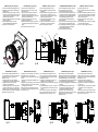
1) Togliere la cuffia posteriore C, e svitare i 4 dadi
D1 che bloccano i tiranti esterni T1
2) Fissare lo scudo anteriore S (con i tiranti
esterni avvitati) al motore di trascinamento
(fig.1A) (coppia di serraggio: 30Nm)
3) Applicare il tirante T per il fissaggio assiale del
rotore avvitandolo a fondo sulla sporgenza
dell'albero motore (fig.1B).
4) Riposizionare il gruppo carcassa e lo scudo
posteriore (fig.1C)
5) Riassemblare l'alternatore, avvitando
nuovamente ai tiranti i 4 dadi di cui al punto 1
(coppia di serraggio 30Nm).
6) Bloccare assialmente il rotore applicando la
rosetta e serrando il dado autobloccante D sul
tirante T con chiave dinamometrica (fig.1C)
Coppia di serraggio:
C30: 40Nm - J609B: 25Nm
Attenzione: prima di applicare il dado osservare
che la porzione filettata del tirante penetri nel
rotore permettendo così un sicuro bloccaggio.
7) Rimontare la cuffia posteriore C
nota: ricordare di rimuovere la protezione
spazzole
1) Remove the rear protection casing C and
unscrew the 4 D1 nuts that lock the external
T1 tie-rods in place
2) Fasten the front shield S (with the external tierods screwed in) to the drive motor (fig.1A)
(Tightening torque: 30Nm)
3) Apply the rod T for the axial clamping of the
rotor, and screw it tight on the engine shaft.
(fig.1B).
4) Re-position the casing unit and the rear shield
(Fig.1C)
5) Re-assemble the alternator by screwing the 4
nuts in Point 1 back into the tie rods
(Tightening torque 30Nm).
6) Lock axially the rotor by placing the washer
and tight the self-locking nut D on the rod T,
using a torque spanner (fig.1C)
Tightening torque:
C30: 40Nm - J609B: 25Nm
Caution: before applying the nut, make sure that
the threaded part of the rod enters the rotor, in
order to obtain a tight lock.
7) Re-assemble the rear protection casing C
Remark: remember to remove brush protection
note: se rappeler d'enlever la protection de
brosses
ISTRUCCIONES PARA EL MONTAJE
nota: recordarse de remover la protección de las
escobillas
Bemerkung: sich erinnern, Bürsten Schutz zu
entfernen
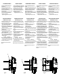
S
T1
T
C
D1
D
fig.1A
fig.1B
fig.1C