1
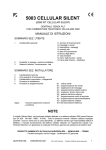
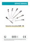
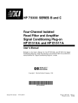
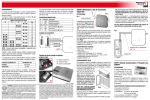
C0403 22-09-2006 14:42 Pagina 1 Italian Design Manuale istruzioni Instruction manual Since 1904 AF904RR Ricevitore universale Universal receiver C0403 22-09-2006 14:42 Pagina 1 INTRODUZIONE AF904RR è un ricevitore universale ad un canale, accessorio del sistema di allarme via radio. Dialoga con tutti i vari trasmettitori del sistema, telecomando AF939R, rivelatore IR-P AF968R e rivelatore perimetrale multifunzioe AF913R. In funzione del trasmettitore al quale viene associato, assume differenti modalità di funzionamento. Può memorizzare fino a 16 codici trasmettitori. 1 C0403 22-09-2006 14:42 Pagina 2 CARATTERISTICHE TECNICHE • Contenitore: ABS Bianco (44 x 67 x 19 mm) • Base installabile con viti a parete; apertura per ingresso cavi sul fondo • Coperchio fissato a scatto su base • Alimentazione: da 10 a 14 Vcc • Assorbimento: minimo 17mA, massimo 32mA a 13,8V in dipendenza dallo stato di funzionamento • 2 relè di attuazione, normalmente eccitati (a sicurezza positiva) • Portata contatti relè: 500 mA max a 14 Vcc • Classificazione della parte Radio - Frequenza della portante: 433.92 MHz - LPD di classe 1 • Portata nominale del collegamento: 30 metri in condizioni normali nell’ambiente abitativo (pareti metalliche o strutture antisismiche possono ridurre la portata di ricezione). • Ambiente di funzionamento: conforme a par. 4.2-02 di CEI 79-2 per apparati da utilizzarsi in interni. - Temperatura ambiente: tra 5°C e 40°C - Umidità relativa massima : 93% a 40°C 2 C0403 22-09-2006 14:42 Pagina 3 RIFERIMENTI NORMATIVI Il prodotto è conforme ai requisiti essenziali ed alle altre disposizioni pertinenti stabilite dalla direttiva 1999/5/CE. DESCRIZIONE FUNZIONAMENTO Programmazione dei trasmettitori 1) Applicare la tensione di alimentazione all’apparecchio mantenendo premuto il pulsante RESET. La memoria del dispositivo viene così azzerata. 2) L3 si accende a segnalare alimentazione presente. 3) Rilasciare il pulsante di reset. L2 lampeggia (condizione di apprendimento codice). 4) Programmare i trasmettitori come di seguito specificato. • Telecomando AF939R: premere contemporaneamente i pulsanti VERDE e ROSSO del telecomando. In questo modo il telecomando trasmette il proprio codice al ricevitore che lo memorizzerà. 3 C0403 22-09-2006 14:42 Pagina 4 • Rivelatori AF968R e AF913R: fornire alimentazione al rivelatore tramite l’apposita pila. Alla prima alimentazione ogni rivelatore trasmette il proprio codice per 30s, questo permette al ricevitore di memorizzare il codice del rivelatore. 5) L’accensione fissa di L2 per 2s conferma l’avvenuta memorizzazione dei codici. 6) Premere nuovamente reset per uscire dalla programmazione. Nota 1: Se si programmano 16 trasmettitori l’uscita dalla programmazione avviene automaticamente (memoria completamente occupata). Per ulteriori dettagli sul funzionamento dei rivelatori vedere da pag. 14 a pag. 23. Aggiunta di trasmettitori (fino a 16) 1) Premere il pulsante di reset con l’apparecchio già alimentato (i codici già memorizzati sono conservati). 2) Rilasciare il pulsante di reset. L2 lampeggia (condizione di apprendimento codice). 4 C0403 22-09-2006 14:42 Pagina 5 3) Programmare, come indicato al punto 4 del paragrafo precedente, altri trasmettitori. 4) L’accensione di L2 per 2s conferma la memorizzazione di ogni nuovo codice. 5) Premere ancora Reset per uscire dalla programmazione. Possibilità d’utilizzo AF904RR dispone di due relè (denominati relè A e relè B) e di 3 LED. In funzione del trasmettitore al quale viene associato, si ottengono le seguenti possibilità d’impiego. Nota 2: i contatti dei relè sono di tipo NA, si chiudono quando i rele vengono eccitati. 5 C0403 22-09-2006 14:42 Pagina 6 Inseritore bistabile comandato da telecomando AF939R (ponticello Jp chiuso). Fig. 1 L1 JP1 Relè 6 5 A 4 L2 3 – + L3 Tamper 2 B 1 Relè Reset Memorizzando il telecomando AF939R, è possibile ottenere il funzionamento descritto in tabella. 6 C0403 22-09-2006 Stato Contatti e LED 14:42 1° Alimentazione Pagina 7 Azione Pressione pulsante rosso Pressione pulsante verde Contatto relè A aperto N° 3 impulsi in chiusura, poi aperto N° 1 impulsi in chiusura, poi aperto Contatto relè B chiuso aperto (condizione di impianto inserito) chiuso (condizione di imp. disinserito) L1 Rosso spento acceso spento L2 giallo spento spento spento L3 Verde acceso acceso acceso In questo caso è possibile, tramite il contatto del relè B, utilizzare il dispositivo per effettuare l’inserimento ed il disinserimento di una centrale via filo, avente un ingresso dedicato a questo servizio. 7 C0403 22-09-2006 14:42 Pagina 8 Ricevitore di segnali di allarme intrusione e/o manomissione (ponticello Jp aperto). Fig. 2 Allarme intrusione Allarme manomissione 6 5 A ➅ ➄ All'ingresso Tamper della centrale via filo B ➃ ➂ All'ingresso di una zona della centrale via filo ➁ ➀ Alimentazione dalla centrale via filo 4 3 – + 2 1 Memorizzando rivelatori AF968R e/o rivelatori AF913R, è possibile inserire rivelatori via radio in impianti realizzati con centrali via filo, come di seguito 8 C0403 22-09-2006 14:42 Pagina 9 specificato. • In caso di trasmissione del segnale d’allarme intrusione da parte del rivelatore, il contatto del relè B segnala lo stato di allarme come di seguito specificato. • In caso di trasmissione del segnale d’allarme manomissione (tamper), il contatto del relè A si apre per 2s. Stato Contatti e LED Contatto relè A Contatto relè B Condizione di riposo chiuso chiuso L1 Rosso spento L2 giallo L3 Verde spento acceso Stato Rivelatore Allarme intrusione Allarme manomissione chiuso aperto per 2 s aperto (per la durata dell'allarme) vedi nota 3 acceso (per la durata dell'allarme) vedi nota 3 spento acceso 9 chiuso spento spento acceso C0403 22-09-2006 14:42 Pagina 10 Nota 3: Il contattto rimane aperto per la durata dell'allarme. Più precisamente: • In caso di allarme intrusione proveniente da un riv. AF968R il tempo di aperttura è pari a 2 s. • Nel caso di allarme intrusione proveniente da un rivelatore perimetrale AF913R, il contatto del relè B resterà aperto fino all'accostamento del relativo magnete (condizione di porta chiusa, fine allarme). • Nel caso di allarme proveniente da un contatto collegato esternamente ad un trasmettitore AF913R il contatto del relè B seguirà lo stato del contatto collegato al trasmettitore stesso. Quando il contatto del relè B è aperto L1 è acceso. Centrale di allarme monozona via radio (ponticello Jp chiuso) Memorizzando un telecomando ed alcuni rivelatori radio, AF904RR può assumere, come indicato in fig. 3, le funzioni di una centrale monozona via radio, dove: • il relè A e L2 danno conferma dell’avvenuto inserimento/disinserimento • il relè B e L2 segnalano lo stato di allarme • L3 segnala lo stato di alimentazione presente. 10 C0403 22-09-2006 14:42 Contatto relè A Contatto relè B L1 Rosso L2 Giallo L3 Verde 1° Aliment. aperto chiuso spento spento acceso Pressione pulsante rosso: centrale inserita N.°3 impulsi in chiusura, poi aperto chiuso spento acceso acceso Condizione di riposo aperto chiuso spento acceso acceso Allarme intrusione aperto aperto per 3 min acceso per 3 min acceso acceso Allarme manomissione (anche con centrale disinsinserita) aperto aperto per 3 min acceso per 3 min acceso (solo a cent. ins.) acceso chiuso spento spento acceso Azione Pressione pulsante verde: centrale disinserita Stato rivelatore Pagina 11 N°. 1 impulso in chiusura poi aperto 11 C0403 22-09-2006 14:42 Pagina 12 MORSETTIERA Morsetto / Ponticello 1 Positivo alimentazione 2 Negativo alimentazione 3-4 Descrizione Contatto N.A. relè B 5-6 Contatto N.A. relè A JP Ponticello predisposizione tamper. Abilita o esclude il tamper antiapertura. È collegato in serie al contatto del relè A 12 C0403 22-09-2006 14:42 Pagina 13 Fig. 3 MORSETTO DI COLLEGAMENTO TROMBA ACUSTICA MORSETTO DI COLLEGAMENTO TROMBA ACUSTICA MORSETTO DI COLLEGAMENTO LAMPEGGIATORE A FLASH MORSETTO DI COLLEGAMENTO LAMPEGGIATORE A FLASH ALIMENTAZIONE + ALIMENTAZIONE – – + 6 MICROINTERRUTTORE ANTIMANOMISSIONE (TAMPER) 5 MICROINTERRUTTORE ANTIMANOMISSIONE (TAMPER) 4 COMANDO SIRENA NC AL POSITIVO 3 COMANDO FLASH NC AL POSITIVO 2 SEGNALE DI FILAMENTO FLASH INTERROTTO (VERSO GND) 1 SIRENA AF53900 + – 3 4 BAT 1+ 2– 5 Fu1 IMP 3+ 4– FUSIBILE J1 J2 ALIMENTAZIONE FUSIBILE ALIMENTAZIONE FUSIBILE AF53897 AF53899 1 2 6 5 6 Rete 230 Vca 13 C0403 22-09-2006 14:42 Pagina 14 AF913R E AF913R-M RIVELATORE PERIMETRALE MULTIFUNZIONE Fig. 4 14 C0403 22-09-2006 14:42 Pagina 15 Caratteristiche tecniche • Alimentazione: pila alcalina 9V - standarad size 6LR16 oppure pila al litio SAFT 9V • Assorbimento: 18µA in stand-by - 20 mA in trasmissione • Autonomia: con pila alcalina 18 mesi - con pila al litio 30-36 mesi • Funzioni operative: - segnalazione di apertura porta - segnalazione di chiusura porta - allarme shock (tentato scasso) - allarme con contaimpulsi (per collegamento esterno di rivelatori inerziali) - allarme tecnico (per collegamento esterno di rivelatori tecnici) • Caratteristiche R.F.: trasmissione A.F. quarzata a 433,92 MHZ potenza max 10mW • Codifica segnali: codice random 36 bit, preimpostato. Oltre 60 miliardi di combinazioni • Portata utile: più di 40 m in aria libera. Circa 30 m in ambienti residenziali • Dimensioni: (135x32x27) mm 15 C0403 22-09-2006 14:42 Pagina 16 Descrizione funzionamento Il rivelatore AF913R ha la possibilità di essere utilizzato in varie funzioni operative, selezionabili tramite appositi microswitch. Come indicato in fig.1, è equipaggiato internamente con un contatto reed (ad ampolla) azionato da un magnete esterno, fornito in dotazione, per essere installato a protezione di porte e finestre. In questo caso il magnete dovrà essere installato sulla porta o finestra da proteggere e il rivelatore sull’infisso. In condizioni di porta chiusa, come indicato dalla fig.4, la distanza tra il rivelatore e il magnete non deve superare i 5 mm. Allontanando il magnete dal rivelatore, il relè reed aprendo il proprio contatto genererà l’allarme che sarà trasmesso in centrale. Riavvicinando il magnete al rivelatore, se il microswitch 3 è in posizione ON, sarà trasmesso in centrale il segnale di fine allarme che annullerà la condizione di allarme. È previsto internamente un dipositivo antishock realizzato con un dispositivo piezoelettrico che in caso di urto violento genera un allarme che sarà trasmesso in centrale. 16 C0403 22-09-2006 14:42 Pagina 17 Questa funzione è escludibile con il microswitch 4. Il rivelatore AF913R permette inoltre di trasmettere in centrale lo stato di un contatto NA o NC collegato esternamente. Collegando quindi opportunamente, come indicato in fig.4, il contatto di uscita di un qualsiasi tipo di rivelatore (riv. temperatura, riv. acqua, riv. inerziale per tapparelle, ecc) la centrale potrà riceverne il relativo segnale di allarme. I microswitch 1 e 2 contaimpulsi (pulse count) permettono di determinare (solo per l’ingresso N.C.) il numero di allarmi locali dopo i quali l’allarme è trasmesso in centrale. Nota 4: L'ingresso NC deve essere abilitato rimuovendo il ponticello JP2. Se l'ingresso NC non è utilizzato JP2 deve restare inserito. È possibile utilizzare contemporaneamente l'ingresso NC ed il magnete, al fine di controllare simultaneamente sia l'apertura di una finestra sia il movimento della relativa tapparella, l'allarme sarà generato o dall'apertura della finestra o dal movimento della tapparella. 17 C0403 22-09-2006 14:42 Pagina 18 La trasmissione di uno stato d’allarme è visualizzata dal LED sul corpo del rivelatore. La tabella di pag. 19 illustra le possibilità di utilizzo del rivelatore AF913R e la relativa predispozione. Installazione Aprire il rivelatore facendo leva con un cacciavite sull’anello di chiusura. Fissare sul muro o sull’infisso il corpo del rivelatore, con viti ove utilizzata la protezione antiscasso. Se installato su vetro, utilizzare silicone e non biadesivo. Allarme manomissione In qualunque monento, aprendo il contenitore dell’apparecchio si ha la trasmissione dell’allarme manomissione tramite apposito microswitch. Tramite un secondo microswitch, posto sul retro della scheda, il rivelatore trasmette anche l’allarme rimozione. L’allarme rimozione può essere attivato o disattivato tramite il ponticello JP1 (vedere fig. 4). Allarme per pila scarica La necessità di sostituzione della pila è segnalata da 3 ”beep”, emessi dal rivelatore (ad ogni trasmissione d’allarme) oltre un mese prima della scarica totale. 18 C0403 22-09-2006 IMPIEGO Protezione porte e finestre Protezione tapparelle, muri (collegamento esterno di rivelatori inerziali o rivelatori a fune) 14:42 Pagina 19 PREDISPOSIZIONE Fissare il magnete (in dotazione) sulla porta o finestra da proteggere, ed il rivelatore AF913R sull’infisso. Selezionare se desiderata la funzione di fine allarme tramite il microswitch 3: ON = fine allarme abilitato OFF = fine allarme disabilitato. Può essere inserita tramite il microswitch 4 la protezione antishock: ON = antishock abilitato OFF = antishock disabilitato Regolare infine il contaimpulsi (pulse count) come indicato in fig. 4 per ottenere un allarme antishock dopo il numero di impulsi desiderato. Abilitare l'ingresso NC rimuovendo JP2.Collegare all’ingresso NC della morsettiera del riv. AF913R il contatto d’uscita (NC) di un rivelatore inerziale a vibrazione o di un rivelatore a fune per protezione tapparelle. Regolare il contaimpulsi (pulse count) come indicato in fig. 4 per ottenere un allarme dopo il numero di impulsi desiderato. Allarmi Tecnici Collegare alla morsettiera il contatto d’uscita di un rivelatore per (collegamento esterno di allarme tecnico. È consigliabile utilizzare l’ingresso NA che esclurivelatori per allarmi tecnici) de automaticamente il contaimpulsi. 19 C0403 22-09-2006 14:42 Pagina 20 AF968R RIVELATORE IR-P - Fig. 5 150° 2m 1m 5m 10 m 15 m Caratteristiche tecniche • Alimentazione: pila alcalina 9V - standarad size 6LR16 oppure pila al litio SAFT 9V 20 C0403 22-09-2006 14:42 Pagina 21 • Assorbimento: 18µA in stand-by - 20 mA in trasmissione • Autonomia: con pila alcalina 18 mesi - con pila al litio 30-36 mesi • Posizionamento: fissaggio a parete, meglio ad angolo, ad una altezza di 22,30 m • Area protetta: apertura 100° per 12m di portata - 20 fasci sensibili su 3 piani • Sensibilità: regolabile con trimmer dal 30 al 100% • Rivelaz. allarme: programmabile, a conteggio impulsi: 1 o 3 (selezionabile tramite ponticello pulse-count) • Test: visualizzazione della rivelazione del movimento tramite LED • Compensazione automatica in temperatura • Caratteristiche R.F.: trasmissione A.F. quarzata a 433,92 MHZ potenza max 10mW • Codifica segnali: codice random 36 bit, preimpostato. Oltre 68 miliardi di combinazioni • Portata utile: più di 40 m in aria libera. Circa 30 m in ambienti residenziali • Dimensioni: (132x65x46) mm • Installazione: per sicurezza installare in posizione non normalmente accessibile dall’utente. 21 C0403 22-09-2006 14:42 Pagina 22 Descrizione funzionamento Dopo 3 minuti dal collegamento della pila, il rivelatore è pronto a funzionare. Rilevato un movimento dà luogo a una trasmissione dall'allarme. Per ridurre il consumo della pila, dopo l'allame si hanno 2 minuti di blocco. Nota: In condizioni di riposo, il LED è sempre spento; si accende solo quando il rivelatore è in stato di allarme oppure in condizioni di test. Test Per effettuare la prova copertura, è necessario porre il rivelatore in condizione di test. A detta funzione, si accede premendo con un cacciavite, il pulsante di test posto nella parte inferiore dell’involucro del rivelatore stesso e si rimane per 2 minuti: si attiva il led di visualizzazione allarmi e si esclude la funzione di blocco rivelatore (per 2 minuti) a seguito allarme. L’ingresso alla funzione di test è segnalato dal rivelatore tramite un “beep”. Regolare a questo punto la sensibilità al minimo necessario agendo sul trimmer posizionato sulla scheda elettronica in alto a sinistra, e in caso di ambienti disturbati spostare il ponticello “conteggio impulsi” in posizione 3 (allarme dopo tre passi circa). 22 C0403 22-09-2006 14:42 Pagina 23 Allarme manomissione In qualunque momento, aprendo il contenitore dell’apparecchio si ha la trasmissione dell’allarme manomissione. Allarme per pila scarica La necessità di sostituzione della pila è segnalata da 3 beep, emessi dal rivelatore congiuntamente alla segnalazione di allarme oltre un mese prima della scarica totale. AVVERTENZE I prodotti devono essere commercializzati in confezione originale, in caso contrario al rivenditore e/o installatore è fatto obbligo di applicare e di trasmettere all'utilizzatore le istruzioni d'uso che accompagnano il prodotto. Dopo aver aperto l'imballaggio, assicurarsi dell'integrità dell'apparecchio, nel dubbio non utilizzare l'apparecchio e rivolgersi a personale professionalmente qualificato. L'apparecchio, anche se imballato, deve essere maneggiato con cura e immagazzinato in luogo asciutto ad una temperatura compresa tra –5…+40°C. Si ricorda inoltre: • Togliere tensione agendo sull'interruttore generale prima di operare sull'impianto. • Curare in modo particolare la preparazione dei terminali dei cavi da inserire nei morsetti dell'apparecchio per evitare la riduzione delle distanze di isolamento tra gli stessi. • Serrare le viti dei morsetti con cura per evitare surriscaldamenti che potrebbero provocare un incendio o il danneggiamento dei cavi. • Il prodotto, se non diversamente specificato, è destinato all'utilizzo in luoghi asciutti e non polverosi. Per ambienti particolari utilizzare prodotti specifici. 23 C0403 22-09-2006 14:42 Pagina 24 INTRODUCTION AF904RR is a one-channel universal receiver, supplied as an accessory of the radio alarm system. It communicates with all the transmitters of the system, the AF939R remote control, the AF968R PIR detector and with the multi-function door-window detector. Depending on the transmitter which it is connected to, it has different operation modes. Possibility of storing up to 16 transmitter codes. TECHNICAL FEATURES • Enclosure: ABS White (44 X 67 X 19 mm). • The support can be installed on the wall by means of screws; opening on the bottom for cable entry • Cover fastened to the support by a release device • Supply voltage: 10 to 14 Vcc 24 C0403 22-09-2006 14:42 Pagina 25 • Current demand: minimum 17mA, maximum 32 mA at 13,8 V depending on the operation mode • 2 normally energised connection relays (positive protection) • Range of the relay contacts: max. 500 mA at 14 Vcc • Grade of the radio section - Carrier frequency: 433.92 MHz - LPD class 1 • Nominal range of the connection: 30 meters under normal condition in the house (all metal walls or anti-seismic facilities could reduce the reception range) • Operation environment: in conformity with par. 4.2.02 of CEI 79-2 for systems to be used indoor. - Room temperature: between 5°C and 40°C. - Maximum relative humidity: 93% at 40°C REFERENCE STANDARDS the product complies with the basic requirements and the related provisions established by directive 1999/5/CE. 25 C0403 22-09-2006 14:42 Pagina 26 OPERATION Programming the transmitters 1) Apply voltage while keeping the RESET push-button pressed. The device memory is cleared. 2) L3 switches on to indicate that power is on. 3) Release the reset push-button. L2 blinks (learning code mode) 4) Programme the transmitters as described below. • AF939R remote control: press the GREEN and RED push-buttons of the remote control at the same time. The remote control transmits its code to the receiver which stores it. • AF968R and AF913R detectors: the detector is powered by its own battery. When each detector is powered for the first time, it transmits its code for 30 seconds and the receiver stores the detector’s code. 5) L2 switches on for 2 seconds to confirm that the codes have been stored. 6) Press reset again to quit programming. Note 1: If 16 transmitters are programmed, programming will be quitted automatically (memory complete). 26 C0403 22-09-2006 14:42 Pagina 27 In order to get more information about the operation of the detectors see from pag. 36 to 45. Adding more transmitters (up to 16) 1) Press the reset push-button when the device is already powered (the already stored codes will be kept). 2) Release the reset push-button. L2 blinks (learning code mode) 3) Programme more transmitters as indicated at point 4 previous par. 4) L2 switches on for 2 seconds to confirm that the new codes have been stored 5) Press reset push button again to quit programming. Applications AF904RR has two relays (called relay A and relay B) and 3 Leds. Depending on the transmitter which it is connected to, it has different applications. Note 2: the contacts of the relays are of the NO type, that-is, they close when the relays are energised. 27 C0403 22-09-2006 14:42 Pagina 28 Bistable circuit-closing switch controlled by the AF939R remote control (Jp jumper closed). Fig. 1 L1 JP1 Relè 6 5 3 – + 28 A 4 L2 L3 Tamper 2 B 1 Relè Reset C0403 22-09-2006 14:42 Pagina 29 By programming the AF939R remote control, the operations shown in the tab. below will be carried out. Status of LEDs and contacts 1 st supply Action Press red push-button Press green push-button Contact relay A open N° 3 closing impulse, N° 1 closing impulse, then it opens then it opens Contact relay B closed open (system on) closed (system off) L1 Red off on off L2 Yellow off off off L3 Green on on on In this case, the device can be used to connect and disconnect a wired control panel equipped with a special input by using the contact of relay B. 29 C0403 22-09-2006 14:42 Pagina 30 Receiver of intrusion and/or tampering alarm signals (Jp jumper open). Fig. 2 Intrusion alarm Tamper alarm 6 5 A 4 2 1 ➃ ➂ To input of one area of the wired control panel 3 – + ➅ ➄ To Tamper input of the wired control panel B ➁ ➀ Power from the wired control panel By programming the AF968R and/or the AF913R detectors, the radio detec30 C0403 22-09-2006 14:42 Pagina 31 tors can be connected to the wired control panel systems as indicated below. • If the intrusion alarm signal is transmitted by the detector, the contact of relay B reports the alarm condition as described afterwards. • If the tamper alarm signal is transmitted, the contact of relay A opens for 2 seconds. Status of LEDs and contacts Contact relay A Contact relay B Quiescent state Detector state Intrusion alarm Tamper alarm closed closed It opens for 2 s closed L1 Red off L2 Yellow L3 Green off on It opens for all the alarm time (see note 3) on for all the alarm time (see note 3) off on 31 closed off off on C0403 22-09-2006 14:42 Pagina 32 Note 3: The contact of relay B contact opens for the alarm time. In details: • In case of "alarm intrusion signal" coming from an AF968R detector, the contact of relay B opens for 2 seconds. • In case of "alarm intrusion signal" coming from an AF913R door/window detector, the contact of relay B opens until the magnet of the AF913R will be closed with the transmitter (end alarm condition). • In case of alarm coming from a contact externally connected to an AF913R detector, the contact of relay B repeats the state of the contact connected to the AF913R. When the contact of relay B is open, L1 is on. One-zone radio alarm control panel (Jp jumper closed) By programming one remote control and some radio detectors, the AF904RR can act as a one-zone radio control panel as shown in picture 1: • relay A and L2 confirm that the connection/disconnection have been carried out • relay B and L2 signal the alarm state • L3 indicates that power is on. 32 C0403 22-09-2006 14:42 Contact relay A Contact relay B L1 Red L2 Yellow L3 Green 1° supply open closed off off on Press red push-button of remote control: control panel On N.°3 closing impulse, then it opens closed off on on open closed off on on open open for 3 min on for 3 min on on open for 3 min on for 3 min on (only if control panel is on) on closed off off on Operation Detector state Pagina 33 Quiscent state Intrusion alarm Tamper alarm (even if control panel is disconnected) Press green push-button of remote control: control panel Off open N°. 1 closing impulse, then it opens 33 C0403 22-09-2006 14:42 Pagina 34 TERMINAL BOARD Terminal / Jumper 1 Positive power 2 Negative power 3-4 Descrizione N.O. contact, relay B 5-6 N.O. contact, relay A JP Jumper for tamper. It enables or disables the anti-opening tamper. It is series-connected to the contact of relay A. 34 C0403 22-09-2006 14:42 Pagina 35 Fig. 3 Terminal for connection of acoustic horn Terminal for connection of acoustic horn Terminal for connection of flash indicators Terminal for connection of flash indicators Power + Power – – + 6 Anti-tamper micro-switch 5 Anti-tamper micro-switch 4 Siren control NC to positive 3 Siren control NC to positive 2 Signal of flash filament interrupted (towards GND) 1 AF53900 Siren + – 3 4 5 J1 J2 BAT 1+ 2– Fu1 ALIMENTAZIONE FUSIBILE ALIMENTAZIONE FUSIBILE AF53897 1 2 IMP 3+ 4– FUSIBILE AF53899 6 5 6 Rete 230 Vca 35 C0403 22-09-2006 14:42 Pagina 36 AF913R E AF913R-M MULTI-FUNCTION DOOR/WINDOW DETECTOR Fig. 4 36 C0403 22-09-2006 14:42 Pagina 37 Technical features • Power: alkaline battery 9 V - standard size 6LR16 or lithium battery SAFT 9V • Current demand: 18µA during stand-by – 20 mA during transmission. • Life: 18 months with an alkaline battery – 30 to 36 months with a lithium battery. • Operational functions: - signal of open door - signal of closed door - shock alarm (attempted intrusion) - alarm by pulse-counter (by external connection of inertial detectors) - technical alarm (by external connection of technical detectors) • R.F. features: Quartz H.F. transmission at 433,92 MHZ, max. power 10mW • Signal coding: 36 bit random code, previously programmed - Over 60 billion combinations. • Working capacity: over 40 m in open space, 30 m approx. In residential environments. • Dimensions: (135x32x27) mm. 37 C0403 22-09-2006 14:42 Pagina 38 Operation The AF913R detector can carry out various operational functions which can be selected by means of special micro-switches. As indicated in Figure 1, it is provided with a REED contact operated by an external magnet supplied with the device which must be installed to protect doors and windows. In this case, the magnet must be installed on the door or window to protect while the detector must be installed on the frame. When the door is closed, as indicated in fig. 4, the distance between the detector and the magnet must not exceed 5 mm. By increasing the distance between the magnet and the detector, the REED relay opens its contact and produces the alarm which will be transmitted to the control panel. By reducing the distance between the magnet and the detector, the signal of end of alarm which interrupts the alarm will be transmitted to the control panel provided that the micro-switch 3 is in ON position. An internal anti-shock device is provided: it consists of a piezoelectric device which, in the case of a violent shock, produces an alarm which is trans- 38 C0403 22-09-2006 14:42 Pagina 39 mitted to the control panel. This function can be desabled by means of the micro-switch 4. By the AF913R detector, the state of an externally connected NO or NC contact can be transmitted to the control panel. Therefore, if the output contact of a detector of any kind (temperature detector, water detector, inertial detector for roller shutters, etc.) is properly connected, the control panel can receive the corresponding alarm signal. By the micro-switches 1 and 2 (pulse count) the number of local alarms can be calculated (only for the N.C. input) and then transmitted to the control panel. Note: NC imput has to be enabled by removing Jumper JP2. If this imput is not used JP2 has to be connected. It is possible to use both NC imput and the magnet, in order to control simultaneously the opening of a window and the movement of its roller blind. The alarm signal will be generated by opening the window or by moving the roller blind. The transmission of an alarm state is displayed by the LED on the detector body. The table of pag. 41 illustrates all possible uses of an AF913R detector and its corresponding location. 39 C0403 22-09-2006 14:42 Pagina 40 Installation Open the detector by levering on the fastening ring by means of a screwdriver. If the intrusion protection is used, fasten the detector body on the wall or the frame by means of screws. Use silicon and not the adhesive tape if it is installed on glass. Tampering alarm At any moment by opening the enclosure, the tampering alarm is transmitted by the corresponding micro-switch. By means of a second micro-switch placed on the back of the card, the detector transmits also the removal alarm. The removal alarm can be connected or disconnected by means of the JP1 jumper (see fig. 4). Alarm of battery discharged 3 ”beeps” produced by the detector (at each alarm transmission) indicate that the battery needs to be replaced over one month before its complete discharge. 40 C0403 22-09-2006 USE Protection of doors and windows 14:42 Pagina 41 LOCATION Place the magnet (provided with the device) on the door or the window to protect while the AF913R detector must be placed on the frame. If you want, you can select the function of end of alarm by means of micro-switch 3: ON = end of alarm enabled OFF = end of alarm desabled. The anti-shock protection can be connected by means of microswitch 4: ON = anti-shock connected OFF = anti-shock disconnected. Adjust then the pulse count as indicated in fig. 4 to produce a shock alarm after the chosen number of impulses. Enable the NC input by removing JP2. Connect the output contact Protection of roller (usually an NC contact) of a vibrating inertial detector or a cord shutters, walls detector for roller shutter protection to the NC input of the AF913R (external connection of detector’s terminal board. Adjust the pulse count as indicated in fig. inertial or cord detectors) 4 to produce an alarm after the chosen number of pulses. Technical alarms (external connection of detectors for technical alarms) Connect the output contact of a detector for technical alarms to the terminal board. We suggest using the NO input which cuts out the pulse count automatically. 41 C0403 22-09-2006 14:42 Pagina 42 AF968R P-IR DETECTOR Fig. 5 150° 2m 1m 5m 10 m 15 m Technical features • Power: alkaline battery 9 V – standard size 6LR16 or lithium battery SAFT 9 V. 42 C0403 22-09-2006 14:42 Pagina 43 • Current demand: 18µA during stand-by – 20 mA during transmission. • Life: 18 months with an alkaline battery – 30 to 36 months with a lithium battery. • Position: Wall-mounting, better if in a corner at a height of 2 to 2,5 meters. • Covered zone: 100° opening for 12 m range – 20 beams on 3 levels. • Sensitivity: adjustable by trimmer from 30 to 100%. • Alarm detector: programmable by pulse count: 1 or 3 (it can be selected by the pulse-count jumper). • Test: detection of movement displayed by LED • Temperature compensation circuit • R.F. features: Quartz H.F. transmission at 433,92 MHZ, max. power 10mW • Signal coding: 36 bit random code, previously programmed - Over 68 billion combinations. • Working capacity: over 40 m in open space, 30 m approx in domestic environments. • Dimensions: (132x65x46) mm. • Installation: for safety reasons, install the device in an zone not easily accessible to the user. 43 C0403 22-09-2006 14:42 Pagina 44 Operation 3 minutes after connecting the battery the detector is ready to start. If a movement is detected, it starts the alarm. To reduce the battery current demand, the alarm is followed by a pause of two minutes. Note: In a quiescent condition the LED is always off. It switches on only if an alarm is detected or during the test. Test In order to carry out the walk test it is necessary to select the test function on the detector, pressing the push button test located in the lower part of the plastic housing. The pause of two minutes after the detection will be excluded for two minutes and the LED on the detector will be enable. A ”beep” indicates the passage of the detector to the test function. Adjust the sensitivity of the detector to the minimum and in case of noisy environment turn the “pulse-count” jumper to position 3 (the alarm starts after 3 steps approximately). Tampering alarm At any moment by opening the enclosure, the tampering alarm starts. 44 C0403 22-09-2006 14:42 Pagina 45 Alarm of battery discharged 3 beeps produced by the detector together with the alarm signal indicate that the battery needs to be replaced one month before its complete discharge. DIRECTIONS The products must be sold in their original packing. Where this is not the case, the retailer and/or the installer must apply and transmit the instructions for use supplied with the product to the user. After opening the packing, check the product’s ntegrity; in case of doubt, do not use the equipment and consult skilled personnel. Even when wrapped in its packing, the equipment must be handled with care and stored in a dry room at a temperature between –5 and +40°C. Remember: • Before working on the system, turn off the voltage by pressing the main switch. • To avoid a reduction in the insulation distances between terminals, carefully prepare the cableheads to be inserted into the terminals of the device. • In order to avoid overheating which could cause a fire or damage the cables, tighten the terminal screws carefully. • If not otherwise indicated, the product must be used in dry rooms free of dust. Use specific products for special environments. 45 C0403 22-09-2006 14:42 Pagina 46 C.403 - 03 - 220906 La garanzia di 5 anni si applica per difetti e non conformità di prodotto imputabili al costruttore fermi restando i diritti e gli obblighi derivanti dalle disposizioni legislative vigenti (artt. 1490, 1512 C.C., DL 24/2002, Direttiva 1999/44/CE, art. 1519 C.C.). Il difetto deve essere denunciato entro due mesi dalla data della scoperta dello stesso. I cinque anni si intendono dal momento della consegna del prodotto da parte di AVE. The 5 years warranty is applicable for any defect in or failing of the goods caused by the manufacturer’s negligence. It doesn’t affect your statutory rights as prescribed by law (art. 1490, 1512 C.C., DL 24/2002, Directive 1999/44/CE, art. 1519 C.C.). The defect must be notified within 2 month from the date it was discovered. Five years are intended from the date of delivery of the goods by AVE.