1
Expandable and remote controlled
Burglar alarm control panel
Cod. AF998EXP
C0463 07 03-02-2009
AF998EXP Expandable and remote controlled Burglar alarm control panel
INTRODUCTION
Page 05
TECHNICAL SPECIFICATIONS
•
Declaration of conformity
Page 05
ARCHITECTURE AND SYSTEMS COMPONENTS
Page 06
SYSTEM PERIPHERIALS
•
AF983 LCD Keyboard
•
Operation of AF983 keyboards
•
AF45380 LED Keyboard
•
AF339 Proximity electronic key and AF45343 decoder
•
AFEX8I Expansion module with 8 inputs
•
AFEX8I-RE Remote expansion with 8 inputs
•
AFEX8U Remote expansion modulo with 8 output
•
AFEX8I-RE and AFEX8U modules and AF983 keyboards connection methods
•
AF907RR Radio expansion module
•
Radio peripherals
•
Programming radio peripherals with AF907RR radio receiver
•
AF899B digital telephone dialler and AF899SV4 voice synthesizer board
•
AF998SW and AFPC01 software and connection cable for programming and remote control
Page 07
SLAVE AREAS
• Forced switch on
Page 23
USER CODES AND SPECIAL CODES
• User codes priority levels (access codes)
• Default programming of the codes
• Modification default values of codes
• Assigned areas
• Associated outputs
• Associated telephone numbers
• Operation of special codes
Page 24
DESCRIPTION AND PROGRAMMING OF INPUTS
• Type of connection
• Type of input
• Input status
• Normal or common input
• Association of inputs to areas
• Enabling buzzer function
• Self-exclusion counter
• Activation
• Report code and relative transmission channel
• Associated telephone numbers
• Associated output
• Input in “AND”
• Alpha-numeric message associated to input
• Modifying alpha-numeric message associated to input
Page 28
DESCRIPTION AND PROGRAMMING OF OUTPUTS
• Type of output
• Activity of output
• Output Timer
• Output connection
• Available timers
• “Open door” signals
• Siren outputs
Page 33
2
AUXILIARY FUNCTIONS
• Signalling status of power supply status (fuses)
• Signalling status of battery level
• Signalling power line failure
• Signalling status of WATCH-DOG
• Autotest
Page 38
SPECIAL FUNCTIONS
• Self test range
• Battery test range
• Power failure delay
• Radio supervision range
• Failure output
• Control panel status at power ON
• Key operation
• TC output with control panel OFF
• Printer output
• Printer output ON/OFF
• Programming code
• Area times
• Temporarily excluded input restoration
• Alarm area output
• Decoder LEDs
• Keyboard messages
Page 40
EVENTS MEMORY
• Viewing last events
• Viewing all events
• Print events
• Remote reading of the event memory
Page 42
TEST FUNCTION
• Input Test
• Siren Test (alarm output)
• Tamper Test
• Battery Test
• Remote output Test
• Communications on telephone line test
Page 43
INSTALLATION AND PROGRAMMING TELEPHONE DIALLER AF899B
• Installation
• Programming telephone numbers
• Telephone options
• Alarm events
• Use of the telephone dialler in bidirectional mode
• Voice synthesis board AF899SV4 and voice messages
• Installation and use of the module AFGSM02
Page 46
CALENDAR
• Setting the weekly scheduler
• Setting holidays
Page 51
3
TIME SCHEDULER
• Setting the programmes
• Extension
• Daylight saving time
• Blocking the time scheduler functions
Page 51
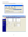
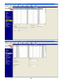
PROGRAMMING THE CONTROL PANEL USING THE P.C.
• Setting the connection modes and parameters
• Local connection
• Remote connection using the telephone modem
Page 54
DEFAULT (FACTORY SET) PROGRAM AND CONTROL PANEL RESET
• Resetting the default code values
• Default values of parameters
• Resetting the default parameter values
Page 56
PROGRAMMING THE CONTROL PANEL USING THE KEYBOARD
Page 60
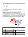
INSTALLATION EXAMPLES
• Factory with apartment
• Two-family house
Page 60
USER MANUAL
• Introduction
• Inserting the system using keyboard AF983
• Checking open inputs and temporary exclusion of inputs through keyboard AF983
• Disconnecting the system using the keyboard AF983
• Inserting, disconnecting and partial inserting the system using the keyboard AF45380
• Inserting, disconnecting and partial inserting the system using proximity key AF339
• Silencing the alarms
• Viewing the last events memory
• Modifying the user code
Page 63
APPENDIX
• Internal view and connections
Page 69
WARNING The products must be sold in their original packaging, if this is not done then the dealer and/or
installer must apply and transmit to the user all the instructions for the use of the product which normally
accompany the product. After having opened the packaging ensure that the apparatus is whole, if there is
a doubt do not use the apparatus and consult qualified professionals. Even if packaged, the apparatus
must be handled with care and stored in a dry place at temperatures between –5…+40°C.
Furthermore please remember: • The 5-year guarantee applies for faults and non conformities in products due to
manufacturing error, all rights and obligations resulting from laws in force remaining firm (arts. 1490, 1512 C.C., DL 24/2002,
Directive 1999/44/CE, art. 1519 C.C.). The fault must be declared within two months from discovery thereof. Five years are
understood as running from the time of delivery of the product by AVE. • The AVE products are for installation purposes. They
must be installed by qualified staff in compliance with systems regulations. • Remove power by switching off the general switch
before undertaking any work on the system. • Take special care in preparing the cable terminals that must be inserted into the
terminals of the apparatus in order to avoid reducing the insulation distances between one and the other. • Tighten the screws of
the terminals carefully to avoid overheating that could cause fire or damage the cables. • The product is designed for use in dry,
non dusty environments. For specific environments use specific products. • There is the danger of electric shock or malfunction
if the apparatus is tampered with. • Install products and accessories according to the specifications in the catalogue and the
appropriate instructions sheets, and in conformity with specific rules and regulations
4
INTRODUCTION
AF998EXP is a fully programmable and expandable burglar alarm control panel. It has 8 basic inputs
expandable to 16 connecting the expansion board AFEX8 internally to the control panel. Through an
appropriate bus line it is possible to connect two remote expansion modules AFEX8I-RE, taking the total
number of inputs managed by the system to 32. Furthermore connecting the radio expansion module
AF907RR the control panel dialogues with other 64 radio devices that can be identified individually. In the
same way the 8 outputs on board can be extended to 32 always connecting the three AFEX8U remote
expansion modules via bus. The control panel can run up to 8 keyboards AF983 and 64 programmable
access codes. The inputs can be grouped into 8 individually programmed areas. The area can be
programmed to run outputs, access codes, keyboards and decoders for electronic keys. This allows
managing the system according to programmable access hierarchies to the various areas.
The control panel has a standard, factory-set programme (default programme), which can be used in the
majority of systems. Modifications to programmes aimed at customising the basic system according to a
client's requirements can be made using the keyboard or an appropriate programme installed on the P.C.,
connected to the serial port RS232 planned for on board the station through the cable AFPC01.
The AF899B board (two-way modem/telephone dialler) allows activating through a remote, tele-managed
device and therefore programme the system from a remote, together with the transmission of alarms on a
telephone line changed to digital. Lastly, inserting the voice synthesis card AF899SV4 alarms can be
transmitted also vocally.
The control panel AF998EXP, thanks to the flexibility of the modularity and the range of peripherals, is the
ideal solution for sophisticated residential systems, average type industrial systems and all those areas that
require specific access logic.
TECHNICAL SPECIFICATIONS
•
•
•
•
•
•
•
•
•
•
•
•
•
•
8 basic programmable inputs such as: instantaneous, delayed, 24H, chime, fire, assistance, attack, silent
alarm, entry route, memory, key, programmer control, switch on.
Possibility of expanding to 16 inputs with AFEX8I card connected centrally
Possibility of expanding to 32 inputs with N. 2 remote modules cod. AFEX8I-RE of 8 inputs each
Possibility of expanding to 96 inputs with 64 radio using the receiver AF907RR.
1 input type 24h for tamper alarm
8 basic programmable outputs
Possibility of expanding to 32 outputs with N. 3 remote modules AFEX8U with 8 outputs each
Possibility of managing up to 8 independent areas
Up to 8 keyboards AF983 and/or AF45380
Up to 64 access codes at various priority levels
Usable with electronic proximity key AF339 and AF45343 decoder
Can be connected, through serial port RS232 to a PC for programming operations
Tele-management with appropriate card AF899B equipped with HAYES interface
Completed with battery AF912 and at least one keyboard AF983
Declaration of conformity
The AF9998EXP control panel and relative wire-connected peripherals conform to the following regulations:
EN 61000-6-3, EN 50130-4, EN 60950, CEI 79-2 2° lev. (after programming relative parameters)
All radio systems conform to the necessary requirements and other pertinent regulations established in the
directive 199/5/CE
The AF899B telephone dialler for the PSTN part conforms to regulation: TBR21
5
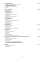
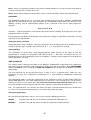
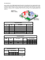
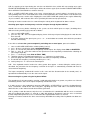
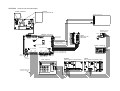
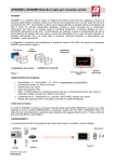
ARCHITECTURE AND SYSTEM COMPONENTS
AF940R
AFEX8I-RE Remote esp.
module with 8 inputs
AF968R-DB
AF913R-DB
AF969R-DB
AF907RR radio
expansion module
AF971R
AFEX8I Remote esp.
Module with 8 outputs
Time programmer
8 programmable
outputs
8 basic inputs
Local or remote (via modem
AF899B) PC connection
AFEX8I Espansion
module with 8 inputs
Fig.1
AF983 LCD
Keyboard
AF45339 and AF45343
Proximity key and decoder
AF45380 LED
Keyboard
6
SYSTEM PERIPHERALS
AF983 LCD keyboard
The control panel AF9998EXP can accept up to 8 keyboards (totally amongst the various models available),
connected through the bus RS 485. For the connection methods and lengths of various cables, see what is
stated in paragraph “Ways of connecting the modules AFEX8I and AFEX8U and keyboards AF983”.
The LCD keyboards have a rear-lit display with 32 characters on two lines and 12 LED with the following
functions:
LCD
LED
LED
Ready
Inserted
ON
OFF
All inputs are closed (not in
alarm)
One or more inputs are in
alarm during the output time
System inserted totally
System disconnected
System inserted partially
Operation normal
Alarm received
Alarm
Technical fault: absence of
mains faulty fuse flat or
faulty battery
Faulty
Area inserted and
associated inputs closed
Area 1- 8
FLASHING
Operation normal
Area not inserted
During the output time this shows
that one or more inputs (in the
same area) are open. The central
station inserted indicates that an
alarm has occurred in the area
and 16 keys divided as follows:
0…9
∗
#
A, B,C,D
numbers keys
key confirming operations
key cancelling operations or cancel
operations key. They have various meanings, described below
Pressing the key is accompanied by an effective tactile effect and a short sound from the buzzer in the
keyboard. From the keyboard it is possible to:
•
•
deactivate the buzzer alone (on each keyboard), pressing keys D and 0 at the same time. Pressing
again these keys the buzzer will be reactivated.
regulate the contrast of the LCD display, keeping key D pressed and pressing A or B
Ways of programming the keyboards AF983
The programming of the keyboards is divided into two phases:
1. one keyboard must be programmed as keyboard N.° 1 and all the others are initially programmed as
keyboard N.° 16
2. all the keyboards (except N.° 1) are assigned progressive addresses.
7
In order to programme the keyboards it is important that at least one keyboard with an address 1, is
connected to the control panel. All the keyboards have a factory setting 16. It is possible to take the
keyboard to address 1 by pressing the following keys at the same time:
∗
0
#
until the wording: “KEYBOARD 01” appears on the display
If more than one keyboard with address 1 is connected, there is a conflict that prevents the correct
operation of the control panel, it is necessary for the other keyboards to have different addresses.
Should it be necessary to take a keyboard to the factory address (16), for some seconds press the following
keys at the same time:
∗
5
#
until the wording: “KEYBOARD 16” appears on the display
Even when it is necessary to change the address assigned to a keyboard, first return its address to 16 using
the procedure described above (* 5 # ).
To programme the operating address for a new keyboard it is necessary for the keyboard to have
address16, be correctly connected to the bus of the central station and the following procedure must be
followed:
1. digit a priority 8 user code (default 123456) on an AF983 keyboard already programmed and then enter
the technical code (default 222222) to enter programming;
2. select by C and D keys the KEYBOARDS menu and confirm by the Key *;
3. on the display of the keyboard on which one is operating the wording " KEYBOARD 02 " appears
indicating which keyboard can be programmed;
4. In the case where a different keyboard must be programmed, use the keys C and D to select the
keyboard that must be programmed and press * to confirm;
5. the display of the keyboard on which one is operating shows the wording " KEY 02 AR. 1 NO " that
indicates the association of area 1 to the selected keyboard;
6. use the keys C and D to change ( NO = area not associated to the keyboard, YES = area associated)
then press * to pass to the association of the next area;
7. carry out the operations seen for area 1 also for the next areas;
8. at the end, confirming the association with the last area, the control panel seeks to dialogue with the
selected keyboard;
9. the control panel checks whether there is a Keyboard 2, programmed previously, and then views
" KEYBOARD 02 OK
PRESS A KEY " while the leds on the interrogated keyboard flash and the
display shows the wording " KEYBOARD 02 OK " , then press the key # on the keyboard on which one
is operating and pass to point 12 to programme other keyboards;
10. on the other hand, if there isn’t a keyboard 2, programmed previously ,the display of the keyboard on
which one is operating will show the wording " PRESS * E # " .
11. Then press the following keys at the same time:
∗
#
on the keyboard that must be assigned the address 02, until the address has been accepted and it acts
as described in previous point 9;
12. Repeat programming from point 3 for all the keyboards that must be programmed.
N.B.: the AF983 keyboard includes an anti-tampering microswitch on board to detect any removal attempts.
In order to use the tamper alarm signal, it is required for each keyboard installed to remove the jumper
placed on the keyboard card near the microswitch and to set the alarm signal through the appropriate option
in the keyboard menù of the program AF998EXP or through keyboard programming in the special function
menù.
8
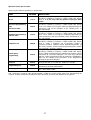
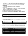
Programming the system using the program AF998SW it is possible to select the following options:
PARAMETER
SET VALUES
PRE-SET VALUE
Keyboard tamper alarm
NO , YES
NO
Keyboards Buzzer
en/ex
NO , YES
NO
Keyboards buzzer
alarm
NO , YES
NO
DESCRIPTION
If this function is selected as NO, the
control panel does not signal the tamper
alarm even if the keyboard is completely
disconnected. In any event the status of
the control panel DOES NOT CHANGE in
view of the connection of the keyboard to
the control panel station.
If this function is selected as NO the
keyboard does not use its buzzer to signal
insertion/disconnection of the system
during the entry time and the exit time
respectively.
If the function is selected as NO the
keyboard does not use its buzzer to signal
the condition of alarm.
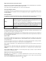
Operation of AF983 keyboards
The AF983 keyboards can freely accept the 8 areas that the control panel can operate, contributing to
establishing the limits in access to the user codes with level 5 priority (see paragraph on USER CODES
AND SPECIAL CODES).
User codes with priority level 6 can operate on all the areas assigned to them regardless of the area
assigned to the keyboard on which they have been entered.
On the other hand user codes with priority level 5 can operate only on those areas coinciding with those the
ones assigned to the keyboard on which they are entered.
AF45380 LED keyboard
The AF9998EXP control panel can support up to 8 keyboards (total amongst the various models available),
connected by bus RS 485. As regards the connection methods and lengths of various cables, please see
what is stated in the paragraph “Methods of connecting modules AFEX8I and AFEX8U and AF983
keyboards”. The keyboard AF45380 has 3 LEDs with the following functions
LED
ON
OFF
FLASHING
Area inserted and
associated inputs closed
Area not inserted
One or more inputs associated to the
area are open during output time, or
there is an alarm in the area.
Area 1
Area 2
Area 3
and 14 keys divided as follows:
0…9
∗
#
A, 3
numbers key
key confirming operations
key annulling or cancelling operations
functions keys. With various meanings, described below
9
Pressing the key is accompanied by an effective tactile effect and a short sound from the buzzer in the
keyboard. It is possible to deactivate the individual buzzer on each keyboard by pressing 3 and 0 at the
same time. Press the same keys again to re-insert buzzer operation.
To proceed with programming it is necessary to have already installed a AF983 keyboard with address 1.
Proceed as follows:
All the keyboards leave the factory with address 16. Should it be necessary to return a keyboard to the
factory setting (16), press the following at the same time for a few seconds:
∗
5
#
Until a beep sounds to confirm the operation.
Even when it is necessary to change the address assigned to a keyboard it is necessary to first return the
address to 16 using the procedure described above ( keys * 5 # ).
To programme an operative address for a new keyboard it is necessary for it to be correctly connected to the
control panel bus and that the following procedure be followed:
1. digit a priority 8 user code (default 123456) on an AF983 keyboard already programmed and then enter
the technical code (default 222222) to enter programming.
2. select by C and D keys the KEYBOARDS menu and confirm by the Key *;
3. the wording " KEYBOARD 02 " appears on the display indicating which keyboard can be programmed;
4. should you wish to programme a different keyboard, use keys C and D to select the keyboard that must
be programmed and press * to confirm;
5. the keyboard display will show " KEYB 02 AR. 1 NO " which means the association of area 1 to the
keyboard selected;
6. use keys C and D to modify ( NO = area not associated to the keyboard, YES = area associated) then
the key * to pass to an association for the next area;
7. the operations mentioned for area 1 can also be used for areas 2 and 3;
8. at the end confirming the association with the last area, the control panel will seek to dialogue with the
selected keyboard;
9. the control panel checks whether there is keyboard 2, programmed previously, and then views
" KEYBOARD 02 OK PRESS A KEY " while the leds on the interrogated keyboard will flash; press
# on the keyboard and pass to point 12 to programme other keyboards;
10. on the other hand, if there isn’t a keyboard 2, programmed previously, the display will show the wording
" PRESS * AND # "
11. press the following keys at the same time:
∗
#
On the keyboard to which address 02 must be assigned, until this accepts the address and replies
behaving as described in point 9;
12. repeat programming from point 3 for all the keyboards that must be programmed.
N.B.: All the AF45380 keyboards connected to the control panel are automatically matched to the first three
areas associated with the code. It is possible to limit access only to one or two areas appropriately
programming the parameters linked to the codes. Furthermore if the code has all the areas associated the
keyboard inserts and disconnects all the areas, with the possibility of shuttering only the first three areas.
For further operative details concerning the use of the system see the user manual.
10
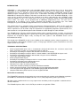
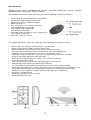
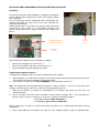
AF339 Proximity electronic key and AF45343 decoder
The IR AF339 ray electronic proximity key and relative AF45343 decoder inserting, disconnecting and partial
inserting the system.
AF339
AF45343-AF441043-AF442043
Max 1m
Programming is in two phases:
1. Assignment to all decoders their own operating address (AF45343 decoders have no factory setting).
2. Transfer of one of the 8 user codes, which the control panel runs, from the control panel to the AF339
key.
To assign the address to the connector proceed as follows:
1. digit a priority 8 user code (default 123456) on an AF983 keyboard already programmed and then enter
the technical code (default 222222) to enter programming;
2. select by C and D keys DECODERS menu and confirm by the key *:
3. the control panel suggests the first Decoder (N.1);
4. enable the decoder to the areas of competence (preferably the same areas of competence as the code
see note 1);
5. the control panel checks whether there is a Decoder N. 1, programmed previously, and then views
"CONNECTOR 1 OK" and the leds of the decoder will flash. On the other hand, if this has not yet been
programmed the wording will be “PRESS A BUTTON” of the AF339 key near the Decoder to which
address N.1 is to be assigned:
6. press the button of the AF339 key (any button) until the three leds of the Decoder flash showing that the
programming has come about, the central station views “DECODER 1 OK” showing that the address has
been assigned;
7. if, on the other hand, after about one minute there is no affirmative result, the display will show an error
message;
8. the operation described must be done for all the decoders that are installed;
N.B.: in order for the proximity key to work correctly, give it only a level 5 code.
Before transferring the level 5 code to the electronic key, it is necessary to programme the user codes into
the control panel, follow the procedure described in the relative paragraph, then continue as follows:
1. digit a priority 8 user code (default 123456) on a keyboard AF983 already programmed and then enter the
technical code (default 222222) to enter programming;
2. on the keyboard digit code 999999;
3. the LCD display shows the wording “CODE “;
4. digit the user code to be transferred to the key (eg. User code n° 2, level 5, if this consists of less than 6
numbers confirm with key “ * ”);
5. the display shows the wording “CODE KEY” and simultaneously all the leds of connector N.° 1 will
start to flash at the same time, indicating that the control panel station is able to transfer the codes to the
key;
6. press the 4 buttons of the AF339 key at the same time until the leds of the key begin to flash indicating
that it is able to accept the code;
7. move the key near until it comes into contact with Decoder N.° 1, as shown in the figure below, keeping
the red button near the lower corner of the Decoder . When the led on the key remains on then the
selected code has been transferred to the key;
8. the display will show the wording “ ***EXECUTED*** “, indicating that the code transfer operation to the
key has been undertaken correctly;
9. a few seconds later the leds on the Decoder will switch off and the control panel activities will resume, the
display will show the situation prior to when code 999999 was entered.
11
Correct position for
memorization of code
inside the remote control
If the operation transferring the code to the key was not successful, it will be necessary to repeat all the
operations starting from point 1.
If more copies of keys are required with the same code it is necessary to repeat the operations for each of
the keys, starting from the beginning. Modification of a user code will annul the keys associated to it. Each
key can memorise up to 8 different codes, with 8 different systems. Each system can be identified using
dipswitches 1, 2 and 3 located on the control panel mother board.
During normal operations the key buttons has the following meanings:
KEY
RED
GREEN
BLACK
BLACK/RED
FUNCTION
Total insertion of all the areas managed by the code (on/off step by step)
Insertion 1st area managed by the code
Insertion 2nd area managed by the code
Insertion 3rd area managed by the code
Note 1: in order to have the leds from one decoder corresponding to the first three areas of the code
associated with the key, it is advisable to associate the same areas as the decoder to the code.
During exit time the three leds of the decoder will view the state of the first three areas of competence of
itself; selecting the option “STATUS OF THE AREAS” , in the special functions menu, this condition remains
even after the exit time has ended.
Selecting the option “STATUS OF THE SYSTEM”, once the output time has ended the leds will view the
status of the system as shown below:
LED
GREEN
YELLOW
RED
ON
System totally on
Faulty Feed Voltage
-
FLASHING
System partially inserted
Alarm
12
OFF
System disconnected
-
AFEX8I Expansion module with 8 inputs
This module allows expanding to 16 the programmable inputs available in the control panel. The inputs can
be configured individually as NC, NO, SINGLE or DUAL BALANCING (alarm and tamper on two wires) and
are filtered and protected against electrical and electrostatic discharges. As shown in the appendix “Internal
view and connections”, it is connected through the cable supplied with the connector EXP3 (CN1).
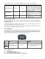
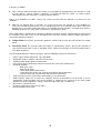
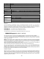
AFEX8I-RE Remote expansion module with 8 inputs
It is possible to connect up to two AFEX8I-RE modules, on bus RS485 falling directly under the terminal
board M4 of the mother board, allowing an extension of the programmable inputs to 32; each input can be
configured as NC (normally closed), NO (normally open), SINGLE or DUAL BALANCING (alarm and tamper
on two wires) and is filtered and protected against electrical and electrostatic discharges.
As shown in the figure, each module has its own address to be set using the bridges J1 (0-1-2). The
modules must be set as follows:
J3
M1
+ A B -
012
M2
+ 1 2 3 4 -
A
B
J2
J1
J1 POSITIONS
MODULE SETTINGS
M3
M2-8IN
+ 5 6 7 8 -
0
1
2
B
A
B
Inputs from 17 to 24
A
A
B
Inputs from 25 to 32
The J3 jumper must be always inserted. The J2 bridge, if inserted, connects the power supply positive +12V
to the terminals + of the M2 and M3 terminal boards.
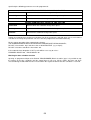
AFEX8U remote expansion modules with 8 outputs
It is possible to connect up to 3 AFEX8U modules to terminal board M4 of the mother board allowing an
extension of programmable outputs, open collector type, to 32 (this type of output closes towards the
negative when it activates. Max 50mA). Like the input modules, each output module has its own address that
must be set using the bridges J1 (0-1-2), as shown below. The modules must be set as follows:
J2
+ A B -
M1
J1 POSITIONS
012
A
B
0
1
2
A
B
B
Outputs from 9 to 16
B
A
B
Outputs from 17 to 24
A
A
B
Outputs from 25 to 32
J1
J3
M2
MODULE SETTINGS
M3
+ 1 2 3 4 -
+ 5 6 7 8 -
M2-8OUT
The J2 jumper must always be inserted. The J3 jumper, if inserted, connects the power supply positive +12V
to the terminals + of the M2 and M3 terminal boards.
13
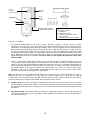
AFEX8I-RE and AFEX8U and the AF983 keyboards connection methods
The maximum overall connection distance of modules and keyboards with the control panel is approximately
1.000 meters. In small building, i.e. 130-150m it is possible to use a normal cable for burglar alarm (2x0,5 for
connection and 2x0,25 mm2 for the signal), and make sure to connect the shield only to the negative of the
power supply in the control panel.
Greater distances, up to 1.000 m, can be reached complying with the following conditions:
•
No losses, excepting only those due to the connection cable, must influence communication. Therefore
the use of a twisted and shielded cable is recommended with a minimum section of 0,5 mm2 (example:
a screened telephone cable or cable type NEC AFA02250/3T2, 39 ohm/Km at 20°C). A twisted pair must
be used for connecting power supply ( + - ) while the other twisted pair must be used to connect the
signals (A B ). This cable must not be interrupted and must not have any intermediate joints.
Intermediate modules must be connected simply by removing the insulation from the cable and inserting
it through a slot into the appropriate terminal. The shield must be connected to the negative of the power
supply in the control panel.
•
In order for the modules to function, minimum feed voltage must be 11 V. In order to guarantee this, for
distances exceeding 200 m it is advisable to use remote feeds (with relative buffer battery) to feed the
detectors or loads connected to the modules.
•
Using the remote power supply to supply modules AFEX8I-RE and AFEX8U, the negative pole must be
connected to terminals “-” in module terminal boards M1, M2, M3, while the positive pole must be
connected to terminals “+” in module terminal boards M2 and M3 taking care to open the jumper J2 for
AFEX8I-RE and J3 for AFEX8U positioned near the terminal board M2 in each case.
NB: the A.M mode to connect remote power supply (open the jumper J2 for AFEX8I-RE and J3 for
AFEX8U) must be always followed, even when it is necessary to use additional power supply, due to high
current consumption, with distances less than 150m.
14
AF907RR Radio expansion module
AF907RR is a radio expansion module that allows the control panel to dialogue with all the peripherals of the
radio range. There are 64 available radio channels that can be freely associated to the inputs from the
control panel, from position 33 to position 96. Each channel can be programmed with the typical input
parameters. It is possible to connect up to 8 radio expansion modules in order to be as close as possible to
the devices and improve the quality of the transmission.
The radio expansion module has an antiscanner function, able to generate al alarm or failure signal even
when there is a disturbance between transmitters and receivers.
N.B.: There are 64 channels regardless of whether one or more AF907RR modules are connected at the
control panel.
The module has the following technical characteristics
•
•
•
•
Feed from bus RS485.
64 radio channels
Field meter with LED on board
LED indicating correct bus communication.
Connecting the receiver on the bus RS485 the following functions can be obtained:
•
Insert– disconnect buzzer. The operations for the insertion, disconnection and partial insertion of the
system can be undertaken using the remote control AF940R, properly memorised.
•
Receipt of alarm from radio detectors. Memorising the radio detectors, as stated below, it is possible
to send intruder and tamper alarms to the control panel, from the detectors themselves.
•
Scanner Alarm. The device has a particular circuit that can detect an attempt at tempering, undertaken
through a scanner. The circuit signals an alarm when it intercepts an attempt to reconstruct the code
normally sent by the remote control, or when a fixed carrier is transmitted.
N.B.: The function must be enabled during installation. The condition of scanner alarm is signalled as “24h
alarm”.
•
Supervision alarm (detector malfunction) the detectors transmit a presence signal every 25 minutes.
Every 8 hours the control panel checks, by the radio expansion module, reception. If the “presence”
signal is absent the control panel signals a condition of supervision alarm as a technical alarm, in order
to direct the calls properly.
•
Detector Tests The AF998EXP central station allows carrying out input tests without this causing alarms
to be signalled, allowing a keyboard display to view this and the sounding of a buzzer on the same. To
enter input tests (see chapter on “TEST FUNCTIONS” ) . It is also possible to check the radio connection
range of the radio devices in the transmissions through the radio expansion module Leds.
15
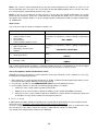
To install the AF907RR radio expansion module proceed as follows:
1. with the control panel not supplied connect the radio expansion module to BUS RS485 and assign an
address using the dipswitch;
Dip1
Dip2
Dip3
Dip4
RECEIVER address
ON
OFF
ON
OFF
ON
OFF
ON
OFF
ON
ON
OFF
OFF
ON
ON
OFF
OFF
ON
ON
ON
ON
OFF
OFF
OFF
OFF
ON
ON
ON
ON
ON
ON
ON
ON
1
2
3
4
5
6
7
8
2. connect power to the control panel and enter a priority 8 user code (default 123456) on an AF983
keyboard and then enter t the technical code (default 222222) to enter programming;
3. select by C and D keys the RADIO MODULE menu and confirm by the key *;
4. the keyboard display will show the wording MOD. RADIO 01 NO;
5. If the radio expansion module with address 01 is connected press key C to modify the parameter to YES
and confirm with *;
6. the keyboard display will show the wording MOD. RADIO 02 NO;
7. repeat the previous procedure, bearing in mind that YES or NO must be set on the basis of the address
of the module.
Eg: Module 1 connected = MOD. RADIO 01 YES, Module 2 not connected = MOD. RADIO 02 NO.
8. the procedure will be repeated 8 times, at the end of which the keyboard display will show the wording
JAMMING NO, set YES to activate the antiscanner function and confirm with * (use this function only in
case of absence of radio transmitters or radio repeaters nearby);
9. if the installation has been successful the bus communication led on each AF907RR module will flash.
Module address.
Led for correct bus
communication
Reception of a formally
correct radio code
1
22 33 44
5
Led Field Measurer.
6 7 8
1 Led: Insuff. Field.
2 Led: Minimum field;
3 Led: Average field;
4/5 Led: Good field
Flashing: radio reception error
Fixed: scanner alarm (jamming)
BUS
PIN 6, in position ON, disables the
TAMPER
16
Radio peripherals
(AF940R Remote control, AF968R-DB PIR Detector, AF913R-DB Multifunction perimetric detector,
AF969R-DB external PIR detector, AF971R IR Barrier)
The AF940R remote control, shown in the figure, presents the following technical characteristics:
•
•
•
•
•
•
•
•
Power supply: two 3V Lithium batteries type CR2016.
Current consumption: 20mA in transmission.
Battery life expectancy: minimum 6 months.
Buttons/channels: 4.
R.F. characteristics: A.F. quartz transmission.
at 433,92 MHZ power max 10mW.
Signal coding: 36 bit random code,
over 68 billion combinations.
Connection range: over 40 m in free air.; approx 30 m.
in residential environments.
Dimensions: (70 x 36 x 13) mm.
The AF968R-DB detector, shown in the figure present the following technical characteristics: ,
•
•
•
•
•
•
•
•
•
•
•
•
•
•
•
•
Power supply: one or two 9 V alcaline batteries – type GP1604A.
Electrical input: 14µA in standby - 80 mA in transmission.
Maximum duration: 18 months with alcaline battery, 36 months with two.
Local signal (beep) flat battery and transmission of the same to the control panel.
Positioning: fixing to the wall, better if at an angle, at a height of 2-2,30 m.
2.
Protected area: opening 100° for a 12m range - 20 sensitive beams on 3 floors, over 80m
Sensitivity: adjustabel with trimmer from 30 to 100%.
Allarm detector: programmable pulse counter: 1 or 3 (selection by jumper).
Temperature autocompensation.
Send signal of presence (supervision) and of flat battery every 22 minutes.
Autoprotection against opening and detachment of detector.
Test: visualization of movement detector via LED for 2 minutes after pressing the button.
Connection range: 100m in free air and in the complete absence of disturbances on the band, it can be
considerably reduced indoors due to the position in relation to the structure of the room and/or
disturbances on the radio waves. Always check the radio range with a suitable test.
Dimensions: (132x65x46) mm.
Operating temperature: from 0°C to +50°C.
Dual Band radio transmission.
17
It operates as follows:
•
After 3 minutes from connection to the battery (see paragraph on “programming”), the detector is ready
to work. When it detects motion it generates a transmission from the alarm. To reduce battery
consumption, after the alarm there is a block lasting 2 minutes.
N.B.: In rest conditions, the LED is always off; it comes on only when the detector is in alarm or in test
conditions.
•
Test. To test whether there is coverage, it is necessary to place the detector in a test condition. To
access this function for two minutes use a screwdriver to press the test button on the lower side of the
detector cover: the alarm viewing led switches on and block detector function is excluded (for 2 minutes)
following the alarm. The entry of the test function is signalled by a “beep”.
At this point adjust sensitivity to the minimum needed by turning the trimmer positioned on the upper left of
the electronic card, and in the case of disturbed areas move the “impulse counter” bridge to position 3
(alarm after about three pitches).
•
Tamper Alarm. At any time, opening the apparatus container will result in the transmission of a tamper
alarm.
•
Flat battery alarm. The need to replace the battery is signalled by 3 ”beeps”, given by the detector (at
each alarm transmission) as well as signalling “Fault” shown on the display, at least one month before it
runs down completely.
The AF913R-DB detector, shown in the figure, have the following technical characteristics:
•
•
•
•
•
•
•
•
•
•
Power supply: alkaline battery 9V – type GP1604A.
Absorption: 13µA in stand-by - 80 mA in transmission.
Autonomy: with alkaline battery 18-24 months.
Local signals (beep) low battery and transmission of the same to the control panel.
Operative functions:
- door open signal
- door closed signal
- shock alarm (attempted break in)
- alarm with pulse counter (for external connection of intertia detectors)
- technical alarm (for external connection of technical detectors)
Send signal of presence (supervision) and flat battery every 20 minutes.
Radio capacity: 100m free air and in the complete absence of disturbances on the band, it can be
considerably reduced indoors due to the position in relation to the structure of the room and/or
disturbances on the radio waves. Always check the radio range with a suitable test.
Dimensions: (135x32x27) mm.
Operating Temperature: from 0°C to +50°C.
Dual band radio transmission.
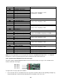
18
Contact
connection
terminal board
Dipswitches
External
magnet
Reed
contact
(bulb)
Impulse Counter
External contact
detector (via
ON
Distance btw magnet
and detector 5mm max
dipswitches:
1-2: impulse counters
3: end alarm
4: antishock insertion
5: exclude anti-removal contact
(ON=excluded)
6: exclude input NC (ON=excluded)
It operates as follows:
•
The detector AF913R-DB can be used in various operative functions, selected using the relative
dipswitches. As shown in fig. it has an internal reed contact (with bulb) activated by an external magnet,
supplied, to be installed to protect doors or windows. In this case the magnet must be installed on the
door or window to be protected and the detector on the frame. With the door closed, as shown in the fig.
the distance between the detector and the magnet cannot exceed 5 mm. Moving the magnet away from
the detector, the reed relay opens its contact generating the alarm that will be transmitted to the control
panel. Moving the magnet near the detector once again, the control panel will receive the end alarm
signal that will annul the alarm condition. The micro switch 3, that signals the end of the alarm, must
always be ON.
•
There is an internal antishock device made using a piezoelectric device that will generate an alarm in
case of violent impact, transmitted to the control panel. This function can only be excluded with micro
switch 4. The detector AF913R-DB also allows transmitting the status of an externally connected NA or
NC contact to the control panel. Therefore properly connecting, as shown in the above reported picture,
the output contact of any type of detector, the control panel can receive the relative alarm signal.
Dipswitch 1 and 2 (pulse counter) allows establishing (only for input N.C.) the number of local alarms
after which the alarm is transmitted to the control panel.
N.B.: The NC input must be enabled through dipswitch 6. If the NC input is not used dipswitch 6 must be
positioned on “on”. It is possible to use the input NC and the magnet at the same time in order to
simultaneously check the opening of a window and the movement of the relative shutter, the alarm will be
generated either by the opening of the window or the movement of the shutter.
•
Tamper alarm. At any time, opening the apparatus container will result in the transmission of a tamper
alarm through the relative micro switch. A second micro switch, located on the back of the card, will allow
the detector to also transmit the removal alarm. The removal alarm can be activated or deactivated using
dipswitch 5.
•
Flat battery Alarm. The need to replace the battery is signalled by 3 ”beeps”, given by the detector (at
each alarm transmission) as well as signalling “Fault” shown on the display, at least one month before it
runs down completely.
19
AF969R-DB is an IR-P detector made in order to be installed inside or outside a home. Thanks to a “curtain”
lens it is possible to offer a perimeter protection. As shown in the installation example the detector can be
installed with all its relative recommendations, to protect the external perimeter of the home. It has a device
against blinding, an obstacle positioned in front of the detector is identified and generates a Tamper alarm.
As for all radio detectors in the range it has a supervisory function. For further information please refer to the
manual included in the package of the product.
•
There is a flat battery signal sent by the detector to the central station. Here the display will show the signal
“Fault”.
AF971R is an infrared ray barrier to protect doors and windows with radio transmission of the alarm. As
shown in the figure, it consists of two devices (master and slave) located in two plastic profiles and fed by
alkaline batteries. A barrier is generated between the two elements, with four invisible and modulated
infrared rays. Breaking one or more rays, depending on the configuration set by the user, will lead to a
transmission of an alarm by radio. For further information please refer to the manual included in the package
of the product.
20
Programming radio peripherals with receiver AF907RR
To programme the remote controls it is important to consider that the 4 channels of the remote control
AF940R, correspond to the 4 buttons on board, and are run from the control panel as single inputs.
Therefore for each channel it is possible to programme parameters typical of inputs. To use a remote control
button to insert, disconnect or partial insert, use the following procedure:
1. digit a priority 8 user code (default 123456) on an AF983 keyboard already programmed and then
enter the technical code (default 222222) to enter programming;
2. select by C and D keys the menu INPUTS and confirm by the key *;
3. use C or D to select the radio input to programme, from 33 to 96. (Press A, the input increases by 10
press B it decreases by 10).
•
•
•
Set the entry type SWITCH ON.
Enter status as INSERTED.
Choose the type of radio channel CH1 or CH2
N.B.: set CH1 if you wish to memorise a radio channel coming from the GREEN, RED or BLACK-RED
buttons of the remote control. Set CH2 if you wish to memorise a radio channel coming from the BLACK
button of the remote control. This button in a learning phase, must be pressed for more than 10”
seconds.
•
•
Confirm the areas managed by the button setting them as YES.
Set the parameter of the input as MEM AL+RI.
N.B.: MEM AL: Inserts (On) - MEM RI: Disconnects (Off) - MEM AL+RI: Inserts and Disconnects (Step by
step).
4.
When these parameters are entered in the keyboard display the writing LEARNING will appear. Press *
to continue learning the radio code.
N.B.: if you wish to modify only the settings of the input press # in order not to have to learn the radio code
again.
5.
At this point the keyboard display will show the wording PROGRAMMING press the button of the
channel that must be memorised;
6. If the control panel has memorised the code, the display will show the wording OK PRESS*. Press *.
7. At this point the control panel will ask whether the input is supervised or not. Set as not supervised
( “NOT SUPERV.” ).
Programmed in this way, the button inserts and disconnects the associated areas.
N.B.: if the control panel is programmed through the PC the radio codes must be memorised with this
procedure.
Similarly, to memorize the detector radio codes it is necessary to place the control panel in condition to learn
the code, as stated below:
1. digit a priority 8 user code (default 123456) on a AF983 keyboard already programmed and then enter
the technical code (default 222222) to enter programming;
2. select by C and D keys the menu INPUTS and confirm by the key *;.
3. Use C or D to select the radio input to programme, from 33 to 96. (Press A, the input increases by 10
press B it decreases by 10).
•
•
•
•
4.
Set the type of input.
Set status as INSERTED .
Choose the type of radio channel CH1
Confirm the areas to which the radio input belongs.
When these parameters are entered in the keyboard display the writing LEARNING will appear. Press *
to continue learning the radio code.
21
N.B.: if you wish to modify only the settings of the input press # in order not to have to learn the radio code
again.
5. At this point the keyboard display will show the wording PROGRAMMING. Memorise the detector code
using the following procedure:
•
supply the detector (IRP AF968R, detector AF913R, detector IRP for outdoors AF968R, Barrier IR
AF971R) by inserting a suitable battery. At the first time the detector transmits its own code for
30s. The control panel will memorise the detector code.
6. If the control panel has memorised the code, the keyboard display will show the wording OK PRESS *.
Press *.
7. At this point the control panel will ask whether the input is or is not supervised.
8. Finish programming the input parameters.
N.B.: If the programming of the control panel is undertaken through the PC the radio codes must
nonetheless be memorised using this procedure.
AF899B digital telephone dialler and AF899SV4 voice synthesizer board
The control panel AF899EXP can support a two way digital telephone dialler AF899B that allows telephone
alarm signals along a PSTN line to tele-surveillance centres, and to connect with centres equipped for telemanagement services. Te use of the AF899SV4 voice synthesizer board allows sending 4 freely
programmable voice messages. For the programming and use of the telephone sequence switch and the
voice synthesis card please see the relevant paragraphs in this manual.
AF998SW and AFPC01 software and connection cable for programming and remote control
The control panel station has a standard, factory-set, programming, in order to be used with the majority of
systems. The changes to the programme aimed at customising the system on the basis of specific need can
be done using the keyboard AF983 or using special programme AF998SW installed on a personal
computer, connected to the port RS232, designed on board the control panel, using the cable AFPC01 (see
paragraphs “Programming the parameters of the central station using the PC and “Programming the default
values of the parameters”.
22
SLAVE AREAS
As mentioned in the introduction, the AF998EXP control panel can run 8 areas independent one from the
other, to which inputs are freely assigned.
In some applications it is necessary to be able to make conditional the inserted/disconnected status of an
area from the status of other areas. The area conditioned (SLAVE) by the status of other areas is not run by
the user but automatically falls under the status of the areas that condition it and namely if all the areas that
condition the slave area are inserted, then the slave area is also inserted.
On the other hand, if at least one area that conditions the slave area is disconnected, then also the slave
area is disconnected.
For each of the 8 areas it is possible to freely programme if it depends on other areas or not by being very
careful that a slave area does not condition the status of other areas.
Furthermore when running the codes the slave areas cannot be run by user codes as this could result in
conflict.
In the default programme no area is slave to any other area.
The need to use slave areas arises when common areas must be managed, such as the entrance stairway
in a building with 2 apartments. In this case the stairway is a slave of the area relating to the two apartments
and therefore only when both apartments are protected will the slave area also be protected.
Forced switch on
If this function is selected as NO, and in the total or partial insertion phase of the system one or more inputs
are open (in alarm), the exit time blocks and does not progress. The output time resumes the count from the
beginning when all the inputs are closed (not in alarm) allowing the total or partial insertion of the system.
On the other hand, if YES is selected the output time is NOT blocked even if one or more inputs are open (in
alarm) and at the end of this time the system will switch on.
Clearly if at the end of the output time all the inputs concerned are not in a close input condition (not
in alarm) then an alarm will be generated.
23
USER CODES AND SPECIAL CODES
The AF998EXP control panel can run 64 USER CODES, i.e. access codes and 10 SPECIAL CODES.
N.B.: the user codes and special codes are freely programmable only through the keyboard.
For each user code it is possible to programme four important parameters:
•
•
•
•
Priority level associated to the code
area of relevance
associated output;
associated telephone call.
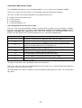
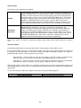
User code priority level of the (access code)
Each user code (also called ACCESS CODE) is associated with a priority level, from amongst 8 available,
that defines the operational level allowed. The hierarchical structure is ascending (minimum level =
priority 1, maximum level = priority 8) and an upper level including all the operational factors of levels
below it. The operational factors tied to the priority levels, are stated in the following table:
HIERARCHICAL LEVEL
8
7
6
5
4
DESCRIPTION
This code allows the operator to insert and disconnect the entire system and
permits the acceptance of the MASTER code (code 33, default 111111).
This code allows the operator to insert and disconnect the entire system and
permits the acceptance of the TECHNICAL code (code 34, default 222222).
This code allows the operator to manage the system according to the areas
programmed independently from the keyboard used.
This code allows the operator to manage the system according to the areas
programmed together with the keyboard used
This code allows the operator only to insert the system according to the
programmed areas together with the keyboard used.
3
This code allows the operator to only silence the alarms
2
This code allows the operator only to view the events memory
1
This code is used only to memorise the event ( passage of patrol etc.) and can
activate an output
The upper level includes all the operational factors of levels below it.
N.B.: at least one user code must maintain priority level 8 to allow access to programming of control panel
parameters and other unused user codes.
All USER CODES can activate a telephone call and a programmable output to be used as an anti-constraint
type signal.
24
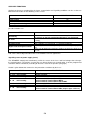
Default programming of the codes
The factory set codes are the following
CODE
FUNCTION
VALUE
PRIORITY
01
USER CODE 01
123456
8
02..64
USER CODE 02….64
----------
6
65
MASTER CODE
111111
---
66
ADVANCED PROGRAMMING CODE (Technical code)
222222
---
67
SIMPLIFIED PROGRAMMING AND TEST CODE
333333
---
68
TELEPHONE CALL
444444
---
69
PC PROGRAMMING
555555
---
70
MODIFICATION TELEPHONE NUMBER 8
888888 FIXED
---
71
MODIFICATION OF OWN USER CODE
000000 FIXED
---
72
TRANSFER OF CODE FROM CONTROL PANEL TO AF339
999999 FIXED
---
Modification default values of codes
It is possible to modify the default values of all the codes; this operation, done when the control panel is
disconnected, requires the following procedure:
1. with the control panel disconnected, digit a priority 8 user code (default 123456) on an AF983 keyboard
already programmed and then enter the MASTER CODE (default 111111 ): the LCD display shows the
wording CODE;
2. enter the code reference number (01...40) that must be reprogrammed, followed by the key * to confirm;
3. the display will show the wording “ CODE XX =“ where XX indicates the reference number entered;
4. enter the new code that must be set, (each code can have 4, 5, or 6 numbers) and confirm by entering *;
N.B.: to abandon the code modification procedure, press #.
5. The LCD display can show the following :
Code accepted
Incorrect code
Indicates that the inserted code has been accepted and replaces the
previous one
Indicates that the procedure followed is correct but the code has not been
modified because there is another code with the same numbers or the
code has not been accepted because the procedure has not been carried
out correctly
6. the code modifying procedure starts again from point 4.
N.B.: the MASTER code can modify all the codes (including the master code itself).
IMPORTANT: all the operations enabled by entering a valid code must be started within one minute after
having entered the code itself.
It is possible to take all the codes to the default values using the procedure indicated in the relevant
paragraph in the section “Programming default”.
25
Assigned areas
Each USER CODE can be freely associated to the 8 areas that allow managing the partial insert of the
system. Each USER CODE with priority 5 and 6 can therefore run only the areas associated thereto. For the
management of the system using the codes, please see the user manual.
Associated Output
Each USER CODE can be associated with a programmable remote output that will be activated each time
the code is entered. The programmable value falls between 0 and 32 ( 0 = no output associated).
N.B.: the same output can be associated to more than one USER CODE.
The output associated to the user codes must be programmed to be the impulse type with activation delay
time and release delay time both equal to 0.
As the activities of programmable outputs can be selected depending on the status of the control panel,
programming will also involve the operation of the outputs associated to the user codes.
N.B.: outputs associated to access codes and inputs at the same time, cannot be used.
Associated telephone numbers
Each USER CODE can be associated to telephone calls. If programmed, each time a code is entered a
telephone notification will be sent to the telephone numbers set.
26
Operation of the special codes
Special codes and their operation are listed below:
NAME
CODE TO BE
ENTERED
Master
111111
Advanced programming
code
(Technical code)
222222
Simplified programming
and test code
333333
Telephone call
444444
Control panel
programming
555555
Modification telephone
number 8
888888
Programming key
999999
Modifying own code
000000
DESCRIPTION
Accepted only if the system if totally disconnected and if
previously enabled by entering a USER CODE with priority
level 8. It is the only code that permits varying all other
codes.
Accepted only if the system if totally disconnected and if
previously enabled by entering a USER CODE with priority
level 7 or 8. Allows accessing the advanced programming of all
parameters and all the functions of the control panel, as
described below.
Accepted only if the system if totally disconnected and if
previously enabled by entering a USER CODE with priority
level 7 or 8. Allows accessing the simplified programming of
some parameters and some functions of the control panel, as
described below.
Accepted only if the system if totally disconnected and if
previously enabled by entering a USER CODE with priority
level 8. Sends a telephone call to telephone number 9
(technical number), allowing remote download operations of
the events memory and the remote programming of the control
panel through a telephone modem.
Accepted only if the system if totally disconnected and if
previously enabled by entering a USER CODE with priority
level 8. Allows programming the control panel through a direct
connection to a Personal Computer. This code must coincide
with the remote programming code of programme AF998SW in
order for the control panel parameters to be programmed
through the personal computer.
Accepted only after having entered a valid code with priority
level greater than 4. Used for the “Follow me” function.
Allows transferring from the control panel to proximity key
AF339 of the desired USER CODE
Is accepted with the system disconnected and allows modifying
one’s own USER CODE
N.B.: entering the technical code (default 222222) inhibits the central station tamper for approximately 60
seconds, in order to allow the control panel to be opened for technical work without causing alarms.
27
DESCRIPTION AND PROGRAMMING OF INPUTS
The programming phase for each input provides for the setting of the following configuration parameters.
1.
2.
3.
4.
5.
6.
7.
8.
9.
Type of connection
Type of input
Status of the input
Normal or Common
association of the inputs to the areas
enabling buzzer function
self-exclusion count
activation
report code and relative transmission channel (for telephone calls to surveillance or telemanagement
centres)
10. associated telephone calls
11. associated outputs
12. inputs in AND
13. alphanumerical message associated with the input
14. modify alphanumerical message associated with the input
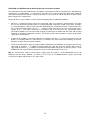
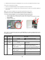
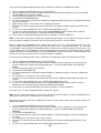
Type of connection
All the inputs of the AF998EXP control panel can be programmed individually as a normally closed type
(NC), normally open (NO), SINGLE or DOUBLE BALANCING.
The various types of connection are illustrated below:
CONTROL
PANEL
CENTRALE
+1 2 3 4-
CENTRALE
CONTROL
PANEL
CONTROL PANEL
+ 1 2 3 4 - INGRESSI
CENTRALE
INPUTS
CONTROL PANEL
INGRESSI
INPUTS
CENTRALE
SHIELDED
CABLE
CAVO SCHERMATO
SHIELDED
CABLE
CAVO SCHERMATO
ALLARME
ALARM CONTACT
(CONTATTO NC)
ALARM
CONTACTNA o NC)
ALLARME (CONTATTO
4.7kohm
SENSORE O CONTATTO
MAGNETICO
DETECTOR
CONTACT
SENSORE O CONTATTO
MAGNETICO
DETECTOR
CONTACT
Connection diagram between one NA or NC input and a
detector
Connection diagram between a single balancing input
and a detector
CONTROL
PANEL
CENTRALE
+1 23 4-
CONTROL
INGRESSIPANEL
INPUTS
CENTRALE
SHIELDED
CABLE
CAVO SCHERMATO
ALLARME
ALARM
(CONTATTO NC)
CONTACT
TAMPER
4.7kohm
4.7kohm
Connection diagram between a dual balancing input and
a detector
DETECTOR
SENSORE O CONTACT
CONTATTO MAGNETICO
N.B.: the dual balancing connection allows the control panel to identify separately the intruder alarm and the
tamper alarm on two wires, of which one is the negative of the power supply.
28
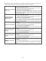
Type of input
The choice of the type of input can be made choosing from among the following options:
TYPE
Instantaneous
Delayed 1
Delayed 2
24 Hours
Fire
Aid alarm
Aggression alarm
Silent alarm
Entry route
Memory
DESCRIPTION
Typical anti-intruder input, active with the control panel inserted and not active
with the control panel disconnected. When there is an alarm it activates a
GENERAL ALARM relay output, the continuous sound of the buzzer and
switching on of the alarm LED on the keyboards. The alarm telephone call to the
associated telephone numbers is activated.
Input active only with the control panel inserted. If open the ENTRY TIME 1 is
started, during which a valid code must be entered to disconnect the control
panel; during this time a continuous buzzer will sound. If the control panel is not
disconnected the exit relay GENERAL ALARM will be activated and the alarm
LED on the keyboards will light up. The alarm telephone call will be sent to the
telephone numbers associated with the input.
Input similar to the previous one with the difference that ENTRY TIME 2 is
started. Alarm activations are the same as for type DELAYED 1.
Instant input active with the control panel inserted and with the control panel
disconnected. Its opening activates the output 24 HOUR ALARM (by default it
coincides with the general alarm relay of the card and can be changed by
programming), the continuous sound of the buzzer (for the duration of the 24H
alarm) and the switching on the alarm LED on the keyboards. The alarm
telephone call will be sent to the telephone numbers associated with the input.
Instant input active with the control panel inserted and with the control panel
disconnected. Its opening activates the output FIRE ALARM (by default it
coincides with the general alarm relay of the card and can be changed by
programming), the continuous sound of the buzzer (for the duration of the fire
alarm) and the switching on the alarm LED on the keyboards. The alarm
telephone call will be sent to the telephone numbers associated with the input.
Instant input active with the control panel inserted and with the control panel
disconnected. Its opening activates the continuous sound of the buzzer and the
visual signalling of the alarm on the keyboards. The alarm telephone call will be
sent to the telephone numbers associated with the input.
Instant input active with the control panel inserted and with the control panel
disconnected. Its opening activates the GENERAL ALARM relay and the
intermittent sound of the buzzer (for the duration of the GENERAL ALARM) and
the visual signalling of the alarm on the keyboards. The alarm telephone call will
be sent to the telephone numbers associated with the input.
Input active with the central station inserted and with the central station
disconnected. No alarm output is activated and no sound or visual signal is
heard or seen on the keyboards. The alarm telephone call will be sent to the
telephone numbers associated with the input.
Instant input active with the control panel inserted. It behaves like a delayed input
only in the case in which a DELAYED 1 or DELAYED 2 type input has already
been opened. It behaves like an instant input in all other situations. The alarm
telephone call will be sent to the telephone numbers associated with the input.
Useful for connecting the detectors located between the entrance door and the
keyboard.
Input active with the control panel inserted. If it is closed (balanced) at the end of
the output time, it behaves like a normal instant-type input. On the other hand if at
the end of the output time it is open, (unbalanced) IT IS IGNORED UNTIL IT IS
CLOSED. From then it behaves like a normal instant-type input. The alarm
telephone call will be sent to the telephone numbers associated with the input.
29
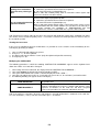
TYPE
Chime
Auxiliary
Key
Time scheduler
Switching ON/OFF
N.B.
•
•
DESCRIPTION
DELAYED 2 input active with control panel inserted, allows the keyboard buzzer
to sound with the central station disconnected. If open with the control panel
inserted, it activates the GENERAL ALARM relay, the continuous sound of the
buzzer and switching on of the alarm LED on the keyboards. The alarm telephone
call will be sent to the telephone numbers associated with the input. With the
control panel disconnected, if the CHIME function is active (BELL ON), when the
input is open it will activate the keyboard buzzers for a time of about 3 seconds.
Instant input active with the control panel inserted and with the control panel
disconnected. Its opening activates the output AUXILIARY ALARM (by default it
coincides with the general alarm relay of the card and can be changed by
programming), the continuous sound of the buzzer (for the duration of the 24H
alarm) and the switching on the alarm LED on the keyboards. The alarm
telephone call will be sent to the telephone numbers associated with the input.
Instant input active with the control panel inserted and with the control panel
disconnected. If unbalanced no visual or acoustic signal is activated. If
programmed, the event is memorised The telephone call will be sent to the
telephone numbers associated with the input.
Useful for conditioning the inputs associated thereto in “AND” configuration when
a mechanical key must be used.
Input active with the control panel inserted and with the control panel
disconnected. If in alarm it blocks all the time programmer functions.
Input used to fully switch on/off the control panel or to activate/disactivate areas.
The way this input operates is established by the programming of parameters as
shown in the Table below.
The items in brackets indicate how the input is indicated if programmed from the keyboard rather
than from the pc.
All the inputs inserted must be associated to at least one area.
Switching ON/OFF input operation depending on assigned parameter
ASSIGNED
PARAMETER
OPERATION
Impulsive NC
(Alarm)
Opening the input the control panel or the areas assigned to the input change
status on/off in step by step mode
Impulsive NO
(Reset)
Closing the input the control panel or areas assigned to the input change status
on/off in step by step mode
Bistable
(All.+Reset)
Input close switches off the control panel of areas assigned to the input.
Input open switches on the control panel of areas assigned to the input
None
(No Memory)
Not valid
The total switching off or shut down of the system through a SWITCH ON type input simulates the centering
of a priority code 8 and blocks telephone calls (if the parameter STOP COMUNIC. OF TELEPHONE
OPTIONS is programmed properly, see relative paragraph).
30
Input status
Each input can take on one of the following status :
TYPE
Excluded
DESCRIPTION
In this state the input is always inactive independently from the state of the control
panel. Even the relative tamper alarm signal is deactivated.
Inserted
The input is active according to the modes established by the TYPE programmed
(see relative paragraph). In this state, alarm conditions the local alarm outputs are
activated, and telephone calls, optical signals and the event is memorised.
Test
The input is active according to the modes established by the TYPE programmed
(see relative paragraph). In this state, in case of alarm the local alarm outputs
are not activated, while optical signals and telephone calls remain active, and
the event is memorised.
Normal or Common Input
Each input can be set Normal or Common.
If a NORMAL-type input is associated with more than one area it will be active even if only one of them is
active, while if a COMMON-type input is associated with more than one area it will be active if all of them are
active.
Association of inputs to areas
Each input can be associated to one or more of the 8 AREAS into which the system can be organised. As
indicated in the user manual at the time of insertion each area can be inserted or not. Resulting in a partial
connection of the system.
It is advisable to associate each input of the NORMAL type to one area only in order to reach maximum
simplicity and flexibility in the management of the system.
Enabling buzzer function
This setting allows choosing whether the input will activate the keyboards buzzer sound.
Self-exclusion counter
It is possible to indicate a number of alarm conditions in the input after which, should there be repeated
alarms from the same input, this will temporarily self-exclude itself until the central station switches off or the
areas to which the input belongs become disconnected.
A number from 0 to 10 can be set for each input, bearing in mind that condition 0 means that the selfexclusion function is not active.
Activation
For each input it is possible to memorise in the events memory the alarm condition and a reset of normal
conditions. The possible choices are:
None
Alarm
Reset
Alarm + Reset
No condition of the input is memorised in events memory
The status of ALARM of the input is memorised in the events memory
The RESET from alarm conditions is memorised in the events memory
Both the ALARM and RESET conditions are memorised in the events memory
N.B.: as the telephone calls keep a record of the contents of the events memory, on the basis of how the
signals for each input have been selected, if the telephone numbers to call have been properly selected for
the inputs, then there can be telephone calls in the case of alarms and/or in the case of reset of the alarm of
the input itself.
31
Report Code and relative transmission channel
They must be set in accordance with the codes necessary for the correct identification by the Surveillance
Company receiving stations, in order to identify the type of alarm.
These codes can have the following values: 0,1,2,3,4,5,6,7,8,9,A,B,C,D,E,F.
Associated telephone numbers
The telephone number to be associated to the input must be inserted. There are 8 available numbers. If one
or more numbers are associated, in the case of opening of the input a telephone call is sent to the
associated numbers.
Associated outputs
It is possible to associate the activation of one of the 32 programmable outputs to each input, this will change
in relation to the variation in input status depending on the programming of the following options:
The output associated to the programmed NORMAL type input is always
controlled when the input is active, and then when at least one of the areas to
which it is associated is inserted, when the input is deactivated and then when all
the areas to which it is associated are disconnected.
Always
ON
OFF
If the input has been programmed of a COMMON type the output associated to
the input is always commanded, whether the input is active, and all the areas to
which it is associated are inserted, or when the input is deactivated and therefore
when at least one of the areas to which it is associated is disconnected.
The output associated to the input is controlled only when the input is active.
The output associated to the input is controlled only when the input is
deactivated.
The choice 00 indicates that no output is associated to the input while selecting a number between 01 and
32 establishes which output is associated to the input.
N.B.: be careful to associate existing outputs as the control panel does not check the presence of outputs at
the time of programming. The same output can be associated to more than one input, while each input can
be associated to one single output.
Input in “AND”
It is possible to establish that an input causes an alarm only if another input is found in the same state of
alarm at the same time. This condition, defined as “AND” condition, links the selected input activation to the
state of another input.
The choice 00 indicates that no input is in “AND” with the one being programmed while selecting a number
from 01 to 32 establishes which input is in “AND” with the one being programmed.
N.B.: associate existing inputs as the control panel does not check the presence of inputs at the time of
programming.
Each input can be in “AND” with another input, clearly different from it, and more than one input can be in
“AND” with the same input. In this situation, the latter becomes an "enable input" for the activation of inputs
in “AND”.
N.B.: no AND conditions are managed in cascade among various inputs (example: an input in AND with
another which is in AND with a third).
Alphanumerical message associated to the input
Each input can be associated to a 16-character alphanumerical message chosen from among 32
programmable messages.
The message associated to the input will appear in the print-out of events, signals of local and remote
alarms, when viewing/printing the contents of the events memory.
32
The choice 00 indicates that no message is associated with the input being programmed while selecting a
number from 01 to 32 establishes which message is associated to the input being programmed.
N.B.: It is possible to associate the same message to various inputs, while each input is associated with only
one message; furthermore, for a better identification of the input it is advisable that in the string of 16
characters making up the message there is also the number that identifies the input.
Modifying the alphanumerical message associated with the input
To vary the message from the keyboard on the LCD panel:
1. digit a priority 8 code (default 123456) on an AF983 keyboard already programmed and then enter the
technical code (default 222222) to enter programming;
2. select by the C and D keys the IMPUT menu and confirm by the key *;
3. enter the relative function and confirm by the key *;
4. use keyboard buttons C and D to select the message to be modified
5. when the message has been selected, enter the message editing function with the key *; the display
views the programmed message and the cursor will position itself at the end of the message.
6. to modify the message act on each letter that makes it up, using the following buttons:
#
Moves the cursor to the left by one space
∗
Moves the cursor to the right by one space
C
D
Changes the character where the cursor is positioned following the sequence of
proposed characters in increasing order
Changes the character where the cursor is positioned following the sequence of
proposed characters in decreasing order
7. To confirm the entire message move the cursor to the last character on the right of the message with the
key * and confirm the entire message by pressing the key *.
DESCRIPTION AND PROGRAMMING OF OUTPUTS
The control panel AF998EXP has 8 basic outputs connected by the connector CN4 (for connection to this
connector there is a special cable available on request). With three external modules AFEX8U it can manage
up to 32 outputs type OPEN COLLECTOR (this type of open collector type output closet towards the
negative in activation conditions. Max 50mA). The activation of the single output is associated to different
conditions such as:
•
•
•
•
•
•
•
•
•
•
•
•
entering an access code;
alarm of an input (alarm/reset);
signalling of a failure;
general alarm;
24 hour alarm;
fire alarm;
auxiliary alarm
buzzer activation;
system ON/OFF;
inputs excluded
system ready
TC output (system status)
For each output the following configuration parameters can be programmed:
• type of output;
• activity;
• timer.
N.B.: The first 8 outputs are available on the connector CN4 of the central station AF998EXP, the other 24
are available connecting three remote output modules AFEX8U.
33
Type of output
Each output can be programmed as follows:
Bistable
Its activity follows the progress of the state of the input to which it is associated. The
output is activated when the associated input is OPEN. If an INSERTION DELAY time
has been set that is different to zero, the input opening starts this time during which
the output remains inactive. At the end of the INSERTION DELAY time, if the input is
still open the output activates and remains active until the input returns to a closed
condition. If a RELEASE DELAY time has been set that is different to zero, the
closure of the input makes this time start during which the output still remains active.
At the end of the RELEASE DELAY, if the input is close, the output is deactivated.
Monostable
(impulsive)
Its activity follows the progress of the state of the input to which it is associated but,
differing from the stable type, it generates an impulse of a desired time. The
INSERTION DELAY TIME must be programmed and the ACTIVATION TIME. The
output is activated when the input is OPEN or when entering a code to which it is
associated. If an INSERTION DELAY time has been set that is different to zero, the
input opening starts this time during which the output remains inactive. At the end of
the INSERTION DELAY time, if the input is still open the output activates for the
programmed ACTIVATION TIME, then it deactivates automatically.
N.B.: Access codes can only be associated to impulsive type outputs with insertion delay times equal to
zero.
Activity of output
Each programmable output can operate with negative safety (default) or with positive safety.
As the programmable outputs are the open collector type, connecting a relay (load) between the output and
the positive feed terminal allows us to obtain a different function depending on whether the output is
programmed with negative safety or positive safety, namely:
-
-
Normally OFF: when the output is active the relay (load) is supplied so that it is energized, while
when the output is not active the relay (load) it is not supplied and so it is not energised;
Normally ON : when the output is active the relay (load) is not supplied so that it is not energized,
while when the output is not active the relay (load) is supplied and so it is energised.
Normally ON (positive safety) outputs are used when the total absence of power supply (battery voltage and
mains voltage 220 Vac) must cause the commutation of the output with the consequent de-energising of the
applied load.
To select the operative mode for the output, choose from among the following options:
Negative (Normally OFF)
Positive (Normally ON)
When active the load is supplied
When active the load is not supplied
34
Output timers
The activity of a programmable output is regulated by three phases and namely :
•
•
•
Insertion phase in which the passage comes about from deactivated to activated output;
Activation phase in which the output is active;
Release phase in which the passage comes about from activated to deactivated output.
The status of a programmable output (active output / deactive output) is determined by the following
conditions :
• The state of the input or inputs to which this output is associated;
• or the digiting of an access code to which the output is associated.
For each output there are three times programmable that regulate the activation and deactivation phases of
the output itself:
Insertion delay time
Activation time
Release time
Period during which the output is inactive; this time is allowed to start, if the
output is deactivated, each time the activation conditions occur, determined
by the change of status of one of the inputs to which the output is associated.
If during this time the cause that led to the start of the activation phase,
is reset, the output does not activate and the insertion delay time is set
to zero.
Period during which the output is active; this time is allowed to start at the
end of the activation phase and establishes how long the output will remain
active even if, during this time, the cause that led to the activation of the
output, is reset.
Period during which the output is active; this time is allowed to start, if the
output is active, when the conditions that have determined the activation of
the output itself, are reset.
If during this time the cause that led to the activation of the output,
reoccurs, the output will remain active and the release delay time is set
to zero.
The three times can be set in the range 0...255 seconds with a precision of +/- 1 second.
Output connection
It is possible to establishes which open collector outputs is activated in case of the following events:
•
•
•
•
•
•
•
•
•
general alarm;
24 hour alarm;
fire alarm;
auxiliary alarm
buzzer activation;
system ON/OFF;
inputs excluded;
system ready;
TC output (system status).
35
Available timers
The AF998EXP control panel is able to manage 8 types of timers for each of the 8 available areas:
TIMES
General alarm
24 hours alarm
Fire alarm
SET VALUES PRE-SET VALUE
0 – 255 s
0 – 255 s
0 – 255 s
DESCRIPTION
180 s
During this time the following are active:
GENERAL ALARM RELAY with positive safety,
which has 2 change over contacts on terminal
board M8;
Any output programmed as general alarm (see
SPECIAL FUNCTIONS).
180 s
The condition of 24 HOUR ALARM is determined by
tampering with the system (TAMPER-type alarm) and
the 24 HOUR-type input alarm.
N.B.: setting output 00 the 24 HOUR OUTPUT
ALARM
(see
SPECIAL
FUNCTIONS).
Is
automatically connected to the OUTPUT GENERAL
ALARM.
180 s
The condition of FIRE ALARM is determined by the
activation of FIRE-type inputs.
N.B.: setting output 00 the FIRE ALARM OUTPUT
see SPECIAL FUNCTIONS). Is automatically
connected to the OUTPUT GENERAL ALARM.
Auxiliary alarm
0 – 255 s
180 s
The condition of AUXILIARY ALARM is determined by
the activation of AUXILIARY-type inputs.
N.B.: setting output 00 the AUXILIARY ALARM
OUTPUT
see
SPECIAL
FUNCTIONS).
Is
automatically connected to the OUTPUT GENERAL
ALARM.
Buzzer alarm
0 – 255 s
0s
The condition of BUZZER ALARM is determined by the
activation of inputs that cause any type of alarm.
20 s
During this time the control panel checks the condition
of the inputs and signals any open inputs (open door
signal). If all the inputs are ready to switch on the
system this condition is signalled by:
a continuous sound of the keyboard buzzer;
the green led READY on the keyboards switches
on.
The opening of an input during the OUTPUT TIME
can block this OUTPUT TIME at its initial value.
20 s
With the system inserted the opening of a DELAYED 1type input activates the counting of ENTRY TIME 1.
During this time the control panel does not
generate alarms if PASSAGE-type inputs or other
DELAY 1 –type inputs are open.
At the end of ENTRY TIME 1 a GENERAL ALARM is
generated.
The
system
must
therefore
be
DISCONNECTED within ENTRY TIME 1 in order not to
cause an alarm. If the input belongs to more areas
the input time will be equal to the shortest input
time of the associated areas.
Output
Entry 1
0 – 255 s
0 – 255 s
36
TIMES
Entry 2
SET VALUES PRE-SET VALUE
0 – 255 s
20 s
DESCRIPTION
With the system inserted the opening of a DELAYED 2type input activates the counting of ENTRY TIME 2
count.
During this time the control panel does not
generate alarms if PASSAGE-type inputs or other
DELAY 2 –type inputs are unbalanced.
At the end of ENTRY TIME 2 a GENERAL ALARM is
generated. The system must therefore be
DISCONNECTED within ENTRY TIME 2 in order not to
cause an alarm. If the input belongs to more areas
the input time will be equal to the shortest input
time of the associated areas.
N.B.: the control panel precision in calculating the timing is +/- 1 unit of time.
“Open door” Signal
During the OUTPUT TIME the control panel checks the condition of the inputs and signals the situation of
inputs open (OPEN DOOR SIGNAL). This signal comes about with:
-
an intermittent buzzer sound from the keyboards;
the green led corresponding to the area where the input is, will flash;
the READY led on the keyboards is off;
N.B.: at the end of the OUTPUT TIME the system, or part of the system becomes active and every alarm is
signalled. If more areas are inserted the output time will be the same as the longest output time of the areas
inserted.
Siren outputs
The central station AF998EXP has a general alarm relay which has available two change over contacts NO,
C, NC connected to with the terminals ALARM 1 and ALARM 2 of the terminal board M8.
The general alarm time is programmed in the function TIMES under the item GENERAL ALARM for each of
the 8 areas. In this way it is possible to diversify this time on the basis of need.
N.B.: power supply outputs connected to the terminal board M8 are protected by a self-resetting fuse F7 that
does not need to be replaced in case of short-circuit.
37
AUXILIARY FUNCTIONS
Similarly to what was mentioned for the inputs, memorisation and signalling conditions can be set that are
both local and remote, for the following service events:
SERVICE EVENTS
PRESET VALUES
Fuses failure
Battery failure
Power line failure
Control panel watch dog
Control panel auto test
No
No
No
No
No
possible imitations are:
SETTING
No memory
Al. mem.
End al. mem.
Al+end al. mem.
Report code and report channel
Telephone numbers
DESCRIPTION
NO condition is memorised in the events memory; in this case also
the signals on the leds and keyboard displays are eliminated.
The status of MALFUNCTION/TEST is memorised in the events
memory.
RESETTING normal conditions is memorised in the events memory
Both conditions are memorised, i.e. ALARM and RESET
Necessary to send and identify the signal to the security company, if
any
Necessary to identify the telephone numbers to which the signal must
be sent.
N.B.: for the watch-dog and autotest the reset conditions have no significance.
Signalling status of power supply (fuses)
The AF998EXP control panel continuously verifies the status of the fuses and feed voltage that recharges
the internal battery. The positive result of the test will not lead to any memorisation, if not the programmed
activations will be considered (according to what was stated in the previous paragraph).
A table is given below that summarises the protections carried out by the fuses:
FUSE
F1 3,15 A
Delayed
F2 0,5 A Self-resetting
F3 1 A
Self-resetting
F4 1 A
Self-resetting
F5 1 A
F6 1 A
Self-resetting
Self-resetting
F7 1 A
Self-resetting
PROTECTIONS
18 Vac Power supply
Battery recharge
Positive terminal Terminal Board M5 and M6 INPUTS
Positive terminal Terminal Board BUS1
Positive terminal Terminal Board BUS3
Positive terminal Terminal Board PC/STAMP.
Positive terminal Terminal Board BUS2
Connector EXP1
Positive terminal Terminal Board M8
Positive terminal Terminal Board CN4 (outputs open collector)
38
In the case of faulty fuse or excess voltage in battery charge, and if enabled, the control panel memorises a
code to identify the fault according to the table below:
SERVICE EVENT
F1 Fuse failure
F2 Fuse failure
F3 Fuse failure
F4 Fuse failure
F5 Fuse failure
F6 Fuse failure
Battery recharge malfunction (volt. > 15V)
MEMORISED EVENT MESSAGE
Power line failure
Battery failure
Power failure 16
Power failure 08
Power failure 04
Power failure 02
Power failure 32
N.B.: in the case of various malfunctions the control panel memorises the sum of malfunction codes as a
numerical code (for example if fuse F3 and fuse F6 fail the control panel: POWER FAILURE 18). The Fuse
F7 failure is not signalled.
Signalling status of battery level
The AF998EXP control panel systematically checks the status of the battery, executing a DYNAMIC TEST at
regular intervals of time defined by the BATTERY AUTOTEST INTERVAL (see paragraph SPECIAL
FUNCTIONS). In the case of positive battery autotest no memorisation will be carried out, while in the case
of malfunction programmed activations for BATTERY FAILURE in AUXILIARY FUNCTIONS, will be
considered.
Signalling power line failure
The Control panel systematically checks the status of the MAINS VOLTAGE 230 Vac checking that it is not
absent for a time exceeding the tone set in the parameter DELAY ALARM DUE TO ABSENCE OF MAINS
(see SPECIAL FUNCTIONS). Once this time of absence of voltage from the mains is exceeded the condition
of malfunction is memorised keeping in consideration the activations programmed for POWER LINE
FAILURE in AUXILIARY FUNCTIONS.
The resetting of mains voltage will be memorised according to the programmed activations.
Signalling status of WATCH-DOG
The circuit supervisor, called Watch-Dog, which the control panel has available, can reset the
microprocessor following problems due to radio, electromagnetic, etc interference.
The intervention of this device is memorised in the events memory, according to programmed activations.
Autotest
The AF998EXP control panel executes a complete test of some vital functions at regular intervals called
AUTOTEST INTERVALS (see SPECIAL FUNCTIONS).
Should the AUTOTEST be positive, no memorisation will be executed, while in the case of malfunction the
activations programmed will be considered.
39
Special function
The following parameters define some important operative modes for the control panel:
PARAMETER
SET VALUES
PRE-SET VALUE
0....255 hours
0 hours
Battery test range
0…255 minutes
10 minutes
Power failure delay
0....255 minutes
30 minutes
Radio supervision
range
0....255 minutes
0 minutes
0..32
0
ON, OFF,
PREVIOUS
PREVIOUS
Self test range
Failure output
Control panel status at
power ON
Key operation
TC output with control
panel OFF
DESCRIPTION
The hourly interval is established when the
control panel automatically carries out a
functional AUTOTEST. This period is also
the time that passes from the start up of
the control panel and the first autotest.
If the set value is 000 the autotest is not
executed
Establishes after how many minutes the
control panel automatically carries out a
DYNAMIC TEST OF THE BATTERY.
Establishes after how much time after the
ABSENCE of MAINS voltage the control
panel will consider this event a malfunction
and, if programmed, inserts it in events
memory (see paragraph on SECONDARY
FUNCTIONS).
Establishes after how much time the
control panel checks the status of the radio
devices installed. The supervision alarm
activates the Technical Alarm output.
It is possible to establish which open
collector type output (1..32) is activated in
case of fault. Programming 0 no output
is activated.
If it is necessary, at the time of the total
feed (battery and mains) for the system to
be completely inserted, then select ON.
Selecting OFF, once both the feeds are
reset, battery and mains, the system will be
completely disconnected, while if choosing
PREVIOUS the system will maintain the
condition as it was prior to the absence of
mains.
On/off, partial ON
Partial ON
If this function is set as Partial ON, the AF342
decoder board allows the partial insert of the
first three areas. Otherwise it inserts and
disconnects areas 1,2,3 in block.
Negative
Positive
Negative
Establishes if, with control panel OFF, the
TC output is negative or positive.
40
PARAMETER
Printer output
Printer output ON/OFF
Programming code
Area Times
Temporarily excluded
input restoration
Alarm area output
Decoder leds
AF45343-AF441043-AF442043
Keyboard message
SET VALUES
TC output,
PC/Printer output
On/off
PRE-SET VALUE
DESCRIPTION
TC output
If the telephone dialler is connected to the
PC/STAMP connector, the serial printer
can be connected to the TC output. In this
case this function must be set as TC output. In
order to know how to connect the printer to
the TC output please call the AVE Service
department, they will give you instructions.
Off
If this function is set as ON, the messages
relating to the activity of the control panel are
directed in real time on the PC/PRINT
connector, used for the local connection with
the P.C. Connecting the cable AFPC01 to the
connector PC/PRINT, and to this a printer
with serial interface RS232 (1200 baud, 8 bit,
No Parity, 1 bit of Stop) it is possible to obtain
an in line print of the activity of the central
station.
Instead of a printer it is possible to connect a
P.C. which has an active terminal programme
such as, for example, Windows HyperTerminal.
Warning: activating the printer output the
operational characteristics of the keyboards
will be considerably slower.
Preceded by
Establishes if to enter programming it is
priority 8 code,
Preceded by priority
necessary to precede the technical code
Direct with control
8 code
by a priority 8 code, or not.
panel off
If this function is set as Separate in the TIMES
Bound areas,
menu it will be possible to define the times for
Separate
separate
each individual area. Otherwise the times of all
the areas are bound to area 1.
If this function is set as Automatic, excluding an
input it is reinserted at the next insertion of the
Manual,
Automatic
system. Otherwise it will be necessary to
Automatic
reinsert it manually, this means a decrease in
the safety of the system.
Area alarm
Establishes if in case of alarm is activated
output,
Area alarm output only the area alarm output only, or the area
Area alarm output
alarm output and the general alarm output
+ general alarm
If this function is set as Status- Associated
Areas, the 3 leds of the AF45343 decoder the
Status associated
Status associated status of the first 3 areas associated with the
areas, Status of
areas
decoder. Otherwise they view the general state
system
of the system (green led INSERTED, yellow
led MALFUNCTION, red led ALARM)
Digit code, On/Off
Digit code
41
This function allows choosing the message that
appears on the keyboard display.
EVENTS MEMORY
The AF998EXP control panel memorizes in an appropriate non volatile memory up to 100 events linked to
the activity of the system; specifically the following are recorded:
•
•
•
•
User codes and special codes that are digited or introduced through the use of the electronic key
Intruder and tamper alarms;
activation / disactivation of the system;
malfunctions of the system.
When the events memory is complete the oldest event is lost leaving space for the recording of a
new event.
It is possible to read the information recorded in the EVENTS MEMORY of the keyboards display scrolling
backwards, starting from the most recent (event N. 001) to the oldest event (event N. 100) without altering
the contents.
N.B.: it is necessary to register the exact date and time in order to allow events to be registered correctly
(see relative paragraph). The regulation of date and time can be done only through the keyboard.
The information viewed when unloading the events memory are:
1.
2.
3.
4.
progressive number (chronologically inverse, event N. 001 is the most recent) ;
description of the event;
date and time when the event was registered;
comment ( optional, not for all events ).
Example : alarm input 11, garage :
EVENT N. 001
ALARM INPUT 11
10:15 10/01/95
GARAGE
progressive number;
description of the event;
date and time of registration;
comment.
N.B.: the Events Memory can be viewed and printed without limits.
Viewing last events
In the case of signals of alarm or malfunction, it is possible to see the relative events immediately on the
LCD display operating as follows:
1.
2.
3.
4.
enter a valid code with priority 2 or greater;
then press key “ C ” on the keyboard;
the display will begin to show the events (only description and any comment);
to end press “#”.
Viewing all the events
It is possible to scroll down on the LCD display and view all the events memory of the control panel, proceed
as follows:
1. digit a priority 8 code (default 123456) on an AF983 keyboard already programmed and then enter the
technical code (default 222222) to enter programming;
2. select by the C and D keys the EVENTS menu and confirm by the key *;
3. the wording EVENT 01 appears on the display showing it can view the most recent event;
4. press “ * ” to confirm, the automatic viewing of information relating to the selected event will begin
(description, date and time, any comment) this takes a few seconds to allow easy reading;
5. use keys “ C ” and “ D ” to pass to other events and the key “ * ” to view contents;
6. to exit press “#” a number of times until the message “ENTER CODE” appears on the display.
42
Print events
It is possible to pass the information relating to the events to the printer output. The automatic printing of the
contents of the archive of normal events in inverse chronological order is achieved by connecting the cable
AFPC01 to the PC/PRINT connector, and this to a printer with serial interface RS232, able to print at least
1200 characters per second, and configured with the following protocol:
1200 baud, 8 bit, No Parity, 1 bit Stop
Alternatively it is possible to connect the cable AFPC01 to the PC/STAMP connector the control panel and to
this the serial port RS 232 of a personal computer on which a terminal programme is allowed to function,
such as Windows’ HyperTerminal, for example.
N.B.: The print events function always start from the most recent and can be interrupted at any time with the
key #.
Remote reading of the event memory
Using a personal computer and software AF998SW it is possible to obtain the remote reception of the
contents of the events memory from the control panel.
For this operation proceed as follows:
1. The programme AF998SW must be started from the personal computer;
2. in the programme select the window RECEIVER;
3. the wording RECEPTION appears and indicates that the automatic response is available for remote calls
from the control panel;
4. with the AF983 keyboard, totally disconnect the system;
5. use the keyboard to enter a USER CODE with priority level 8;
6. use the keyboard to enter the TELEPHONE CALL CODE (default 444444 ): the LCD keyboard will show
the wording REMOTE CONNECT;
7. the control panel starts the telephone call to telephone number 9 (technical telephone number that should
have been previously programmed locally through the personal computer). Once the number has been
dialled the control panel remains in the synchronisation situation described in point 4) for a few seconds
waiting to start communicating with the computer;
8. when the telephone call arrives, the programme AF998SW receives and views the data from the control
panel concerning the contents of the events memory and, if previously programmed to do so, will save
them in an archive file that can be viewed and printed thereafter;
9. the correct outcome for the procedure unloading the events memory is shown in the wording
TERMINATED SUCCESSFULLY while if the procedure has not been completed correctly the wording
will be UNLOAD NOT COMPLETED; in this case repeat the procedures stated above.
N.B.: It is possible to interrupt the RECEPTION procedure at any time using the key ESC on the computer
keyboard and this event will be confirmed with the wording “TERMINATED BY THE OPERATOR”.
TEST FUNCTION
Input tests
The AF998EXP control panel allows carrying out input tests without this causing alarm signals and viewing
inputs in alarm on the display and the keyboard buzzer being activated.
To enter input test proceed as follows:
1. digit a priority 8 user code (default 123456) on an AF983 keyboard already programmed and then enter
the technical code (default 222222) to enter programming;
2. select by the C and D keys the IMPUT TESTS menu and confirm by the key *;
3. the control panel will view the analog reading of the feed, fuses, and inputs;
4. press “#” to view INPUT TESTS;
5. at this point act on the input, the relative status will be viewed on the keyboard display;
6. to exit press “#” for a few seconds.
N.B.: during the INPUT TESTS function the events memory memorises the activities of the inputs.
Consulting the contents of the events memory (see paragraph EVENTS) it is possible to see the sequence of
activations memorised during the input tests.
43
Should a personal computer be locally connected to the relative serial output (identified on the control panel
station with the wording COMPUTER) and it is set in TERMINAL / COMPUTER mode, it will receive and
view the information relating to the inputs in alarm in the sequence in which they have been activated, giving
the installer a very useful pathway to check the operation of the inputs.
Sirens test (alarm outputs)
The AF998EXP control panel allows executing the test of all the alarm outputs found on the card by
activating them individually for a time of approx. 4 seconds, at the end of which the alarm output returns to a
state of deactivation.
Therefore the status of the following alarm outputs can be checked:
• GENERAL ALARM OUTPUT AND SELF-POWERED SIREN
• ON/OFF OUTPUT
N.B.: For the entire time when the alarm output is active, the display will show, next to the description of the
selected alarm, the wording >> * <<;
Tamper test
The AF998EXP control panel allows executing the control panel tamper input test, found on the terminal
board M7, without alarming the control panel and therefore without setting on the installed sirens.
To carry out the control panel tamper test:
1) Place jumper JP1 in position A (open)
2) Press the button “ * “ to activate the CONTROL PANEL TAMPER TEST function
At this point the LCD keyboard display will view the wording:
•
•
CONTROL PANEL TAMPER CLOSED: if the contact connected to the terminal M7 is closed
CONTROL PANEL TAMPER OPEN: if the contact connected to the terminal M7 is open (in this case
the buzzer is also activated).
N.B.: the JP1 JUMPER in position C (closed) short circuits the control panel tamper input and consequently
makes it inactive, while in position A (open) it makes it active.
Battery test
The AF998EXP control panel allows executing a dynamic test of the battery; this consists in reducing the
voltage issued by the DC power supply of the control panel for a time of approximately 1 second in order to
allow the buffer battery to come into operation and then check the charge status (see paragraph on
SPECIAL FUNCTIONS).
At the end of the test the keyboard display shows one of the following wordings:
• BATTERY OK
• BATTERY FAILURE
if the test results are positive
if the test results are negative
N.B.: the battery test does not influence the normal operation of the control panel.
44
Remote output tests
The control panel allows carrying out the test of the remote outputs activating them individually for a time of
approximately 4 seconds at the end of which the alarm output returns to a state of deactivation.
After having selected the desired output XX, press the confirm key found near the wording “ OUTPUT XX
TEST? “ on the keyboard display the activation test for the selected output will begin.
The activated output condition is determined by the appearance of the wording “ OUTPUT XX ON “ on the
keyboard display.
Communication on the telephone line test
If the mode COMMUNICATIONS TEST is selected even without being enabled from the keyboard, the
following operations can be undertaken:
•
•
•
REMOTE PROGRAMMING OF FUNCTIONAL PARAMETERS FROM THE CONTROL PANEL;
RECEPTION OF THE CONTENT OF THE EVENTS MEMORY OF THE CONTROL PANEL;
RECEPTION OF PROGRAMMING FROM THE CONTROL PANEL.
N.B.: This operation significantly decreases the safety of the system and therefore it must be used only to
check functions and not as an operating mode.
To receive instructions regarding the tele management from remote PC, contact the AVE telephone service
centre using the toll-free number.
45
INSTALLING AND PROGRAMMING THE TELEPHONE DIALLER AF899B
Installation
To install the telephone dialler AF899B it is important to completely
remove voltage to the control panel (remove mains voltage and the
back up battery).
Insert 4 plastic pins into the appropriate holes found above the
control panel board (see figure here on the side) and hook the
telephone dialler board.
Having obtained the result shown in the figure below, proceed by
connecting the white cable to the PC/STAMP connector ircuit
closing switch located on the upper left hand in the control panel
board.
Telephone dialler
inserted correctly
Plastic
pins
PC/STAMP
connector
Connection to the telephone line must be done as follows:
•
•
•
Connect the telephone line to terminals L L
Connect any telephone apparatus to the terminals T T
Connect GND by using the appropriate terminal
Programming telephone numbers
To programme telephone numbers using the keyboard proceed as follows:
1.
2.
digit a priority 8 user code (default 123456) on an AF983 keyboard already programmed and then enter
the technical code (default 222222) to enter programming;
select by the C and D keys the TELE. NUMBERS menu and confirm by the key *;
N.B.: The control panel allows programming 9 telephone numbers. Numbers 1 to 8 are used to send alarm
situations, while telephone number 9 is used for remote programming via PC.
3.
With keys C and D it is possible to scroll through the 9 numbers and choose the one to be set
confirming it with *
4. enter the numbers that make up the telephone number and then confirm with *; over and above the
numbers there are also the characters C, P, that are used for the following functions:
C = in the case of a PABX switchboard
P = to insert a pause during composition
N.B.: the characters C and P are selected respectively using the keys C (switchboard) and A (pause during
composition).
5. At this point follow the instructions that appear on the keyboard display using the following table:
46
OPTION
Code
N.° Communication attempts
Communication Protocol
MEANING
Identifying number of the system used when transmitting
alarms in digital protocol to security companies
Sets the number of attempts which the control panel will
carry out for each of the 8 programmed telephone
numbers, if the “end call” sign is not received (see note 1)
It is possible to choose:
• Digital Protocol Contact ID” (see note 2)
• Voice Synthesis (one of 4 messages run by the
AF899SV4 board)
• PC for remote programming with AF998SW
• SMS (see note 3)
Note 1: the “end call” signal is obtained by pressing 5 on the telephone of the user called, in the case of
transmission with voice message. In case of transmission with digital protocol, when it receives the alarm the
security company automatically generates this signal.
Note 2: The device permits the transmission of alarms in “Contact ID” protocol towards security companies.
(from ver. EPROM 3.4). For all the details relating to this application request the relative documentation from
the AVE S.p.A. technical services office
Note 3: the selected telephone number will receive an SMS with the description of the event that has taken
place, together with the time and date (from ver. EPROM 4.4). Option available only with module GSM
AFGSM02 installed. Example:
GEN. ALARM
14.00 05/03/08
Telephone Options
Option
Meaning
Sequence called
Set if, in the case of communication NOT successful (and
if the telephone number called is busy, for example), the
same telephone number will be attempted immediately or
if the communicator must proceed with the selection of
other telephone numbers.
End call cycles
Set if the first call that receives the signal “ end call” (see
note 1) must determine the block of all subsequent calls,
even of other telephone numbers.
Stop switch off
Set if the cycle of telephone calls can be interrupted by
centering a valid level 5 or greater priority code.
Free line Tone
Determines whether, before starting the cycle of calls the
sequence switch must check if the line tone is present or
absent
PSTN/GSM Priority
If module AFGSM02 is installed and the PSTN line has
been connected, it determines which of the two lines has
priority over the other.
Duration of pause between two calls
Allows selecting the time interval between two consecutive
calls to the same telephone number (0 - 60 seconds).
Digital format
Sets the type of digital format. Setting is supplied by the
security company.
47
Note 1: the “end call” signal is obtained by pressing key 5 of the telephone of the called user, in the case of
transmission with voice message. In the case of transmission with digital protocol, when it receives the alarm
the security company automatically generates this signal.
Note 2: in the case of reception of an alarm call, press the key 0 to enter DTMF control mode. The control
panel will emit a long tone, it waits for a valid code to be entered and then allows the use of remote controls
described in the paragraph below “Use of the telephone dialler in bidirectional mode” (function available from
rel. EPROM 4.4).
Alarm events
The events that start the call to the telephone numbers are:
EVENT
PROGRAMMING
•
•
•
•
•
Central station disconnected
Central station inserted
Reset alarm
General Alarm
Central station partially inserted
Association of telephone numbers through programming
menu
“RAP. CODES”
•
•
•
•
Battery malfunction
Mains malfunction
Watch dog ( System Error)
Autotest
Association of telephone numbers through programming
menu
“SECONDARY FUNCTIONS”
•
Single input Alarm
•
Entering a code
Association of telephone numbers through programming
menu
“INPUTS”
Association of telephone numbers through programming
menu
“CODES”
N.B.: If, when programming the options, a telephone number has been associated with the ID contact digital
protocol, in alarm events it is not possible to associate the transmission to a voice message.
Use of the telephone dialler in bidirectional mode
AF899B can also be called from a remote telephone to carry out activations. In this situation it is necessary
to undertake the following operations:
1. digit a priority 8 user code (default 123456) on an AF983 keyboard already programmed and then enter
the technical code (default 222222) to enter programming;
2. select by the C and D keys the COMUNICATION TEST menu and confirm by the key *;
3. Set the LINE parameter as desired, remembering that operation is as follows:
4.
•
PSTN Line the central station responds on PSTN line;
•
GSM Line the central station responds on GSM line (if the module AFGSM02 is installed);
•
AUTO Linea the central station responds on GSM line in remote controls management mode and
on PSTN line to carry out the remote tele management from PC.
Press “ # “ to exit.
In bidirectional operation, should the Control panel respond with the GSM mode, the caller number must be
entered in the first 4 positions of the phone book memorised in the control panel.
To run the telephone dialler by remote, one in line with the it, it is necessary to enter an authorisation code
level 5 or greater. If the code is correct the sequence switch will emit 3 beeps in confirmation.
The controls for management by remote are the following:
.
48
KEYS
9000
9001
9002
9003
9004
9005
9006
9007
9008
FUNCTION
Interrogate control panel status
Interrogate status area 1
Interrogate status area 2
Interrogate status area 3
Interrogate status area 4
Interrogate status area 5
Interrogate status area 6
Interrogate status area 7
Interrogate status area 8
ACOUSTIC SIGNAL
3 beeps = ON, 1 long beep = OFF,
20 short beeps = ALARM
0000
0001
...
0008
Disconnection control panel
Disconnection area 1
.......
Disconnection area 8
3 beeps = OK, 1 long beep = FAIL
1000
1001
....
1008
Insert control panel
Insert area 1
.......
Insert area 8
3 beeps = OK, 1 long beep = FAIL
2001
...
2032
Interrogate status input 001
.......
Interrogate status input 032
3 beeps = NO ALARM, 1 long beep = ALARM
4001
...
4032
Interrogate status output 001
.......
Interrogate status output 032
3 beeps = ON, 1 long beep = OFF
5001
...
5032
Disconnect output 001
.......
Disconnect output 032
3 beeps = OK, 1 long beep = FAIL
6001
...
6032
Activate output 001
.......
Activate output 032
3 beeps = OK, 1 long beep = FAIL
7000
7001
7002
Interrogate status battery
Interrogate status fuses
Interrogate status mains
3 beeps = OK, 1 long beep = FAIL
3 beeps = OK, 1 long beep = FAIL
3 beeps = OK, 1 long beep = FAIL
N.B.: For correct operation it is necessary to enter YES in the COMMUNICATIONS TEST
PROG.menu, if not it is possible only to insert the control panel but not to disconnect it.
REMOTE
Voice synthesis board AF899SV4 and voice messages
The voice synthesis board AF899SV4 allows the transmission of 4 voice messages. It has a button and a
Led for each of the 4 messages.
Messages 1
Messages 2
Messages 3
Messages 4
To register the messages proceed as follows:
1. Press for more than 2 s the button of the message to be recorded, until the corresponding Led lights up,
keep the button pressed for the whole duration of the recording. ( max. time 10s )
49
2. Should you wish to interrupt the recording before 10s are up release the button of the relative message.
To hear the message proceed as follows:
1. Connect a 8 ohm/0,25W loudspeaker to the appropriate connector on the board.
2. Press for more than 2 s the button of the message to be heard. The voice message will be reproduced
automatically.
N.B.: at the end of the recording the message will be reproduced for relative checks.
Installation and use of the module AFGSM02 (functioning with rel. EPROM 3.4)
To install the module AFGSM02 it is necessary to follow the operations below in order:
• Remove voltage to the control panel (remove mains voltage and the battery);
• Fix the electronic card in its housing (CN1 connector) and assemble the aerial outside the control
panel (see figure);
• Insert SIM card;
• Supply the control panel.
When voltage is returned the first 4 leds on the card AF899B light up in sequence, indicating that the check
phase of the new module is inserted by the sequence switch. At the end of the procedure the leds take on
the following meaning:
LED
COLOUR
1
Green
2
Red
3
Green
4
Yellow
5
Green
TYPE OF FLASHING
MEANING
NOT USED
The control panel is connected with the
Hayes telemanagement module
With module GSM installed it views in impulses the level of the GSM signal picked
up, from 0 to 4.
On fixed
The control panel is communicating with the
GSM module
On fixed
Slow
(time led on = time led off)
0.5 ON – 0.5 OFF
GSM network signal low or no network.
Attempt to reconnect underway.
(if persists check the correct insertion of the
SIM, switch the control panel off and on)
Fast
(time led on less than time led off)
0.3 ON – 2.7 OFF
CORRECT functioning, cover present.
Off
GSM module not present
On fixed
Call underway (signals only incoming calls)
50
Note 1: There is no particular function to carry out the telephone dialler test, just open an input associated to
a number and check the execution of the call.
Note 2: All the SIM insert/disconnect operations must be carried out with the control panel disconnected.
CALENDAR
The AF998EXP control panel, has an internal clock/calendar that can manage a WEEKLY SCHEDULER
with which to automatically execute some operations. The CALENDAR function allows each day of the week
(Monday...Sunday) and 32 programmable holidays to be associated to one of the eight programmes
available :
A, B, C, D, E, F, G, H
Selecting “-“ with the programme associated to a day of the week or a holiday, for that day none of the eight
programmes will be executed.
Each programme will contain the information concerning hours and types of operations that will be executed
and which are described below.
Setting the weekly scheduler
Programming the weekly scheduler is done by selecting the day and choosing one of the programmes from
among the possible types available: A,B,C,D,E,F,G,H, or “-“ ("-" = no programme selected).
Setting holidays
The 32 holidays are special days, freely programmable by month and day. At the expiry of each day
programmed as a holiday, the programme A,B,C,D,E,F,G,H, or “-“ will not be executed in the way it is
programmed for the corresponding day of the week (Monday .. Sunday), but the programme entered for that
specific day will be executed.
TIME SCHEDULER
This function allows setting the operations of the WEEKLY SCHEDULER establishing the 8 programmes
A,B,C,D,E,F,G,H that could be assigned to the days of the week and to 32 holidays. Each PROGRAMME
contains 20 STEPS, each is assigned the TIME and ACTION that the control panel AF998EXP undertakes
automatically.
The same ACTION can be repeated more times as long as this is at different times, within the same
programme. As there are 8 programmes available there is a high flexibility in controlling the automated
functions.
The programmed action is carried out automatically by the control panel ONLY AT THE EXACT TIME SET
(HOUR AND MINUTES). If an action programmed at a certain time is not executed for any reason and the
control panel clock has passed this time, this action will not be executed within the same day. It is not
necessary to follow an increasing time sequence when setting the action within the programmes.
N.B.: it is important to be very careful in the choice of actions executed automatically by the control panel
as, if these are not programmed correctly they can lead to undesirable operations.
Setting the programmes
For each of the 20 programme steps it is necessary to select the following parameters:
HOURS
(possible values 00..23) hour in which the programmed action will occur
MINUTES
(possible values 00..59) minutes in which the programmed action will occur
51
ACTION
0
1
2
3
4
POSSIBLE OPTIONS
No action
Complete insertion / disconnection of the control panel
activation / disconnection of an output
insertion / disconnection of an area
block / unblock codes.
NUMBERS
Action = 1 :
Action = 2 :
action = 3 :
action = 4 :
STATUS
Action = 1
Action = 2
Action = 3
Action = 4
NUMBER
NUMBER 0..32
NUMBER 1..8
NUMBER 1..8
POSSIBLE OPTIONS
no effect on the action
identifies the address of the output to be activated/deactivated;
identifies the area to be inserted/disconnected;
identifies the priority of codes on which to execute the block.
POSSIBLE OPTIONS
Status 0 = complete disconnection of the control panel;
Status 1 = complete insertion of the control panel;
status 0 = disconnect the output;
Status 1 = activate the output;
status 0 = disconnect the area;
Status 1 = insert the area;
status 0 = block codes;
Status 1 = unblock codes;
Extension
The time programmer automatically executes the programmed actions in the times set. If you wish to
intervene in the programmed action suspending it for a limited amount of time (for example delaying the
automatic insertion of the control panel by one hour to allow an extraordinary action) it is necessary to
programme the submission of the said action, in the relative programme step, to the extension.
EXTENSION YES = the action has been subjected to extension
EXTENSION NO = the action has not been subjected to extension
The two parameters that determine the operational function of the extension are:
•
•
EXTENSION TIME stated in minutes (from 30 to 60 minutes);
NUMBER OF other REQUESTS for extension (from 0 to 4).
The request to activate the extension comes about by entering the special code 38 (default 666666).
This operation starts the extension time during which ALL the automatic actions controlled by the time
programmer, and subjected to extension, are suspended. At the end of the extension time the suspended
actions will be executed.
Before the extension time expires another request can be executed, by entering the special code 38 (default
666666), for the number of times compatible with what was programmed. On the other hand if the extension
must be interrupted digit the special code 39 ( default 777777 ) that will launch a residual period of about 10
minutes after which the suspended actions will be executed.
When an extension period has ended (in terms of time or interruption by special code 39), the number of
requests will return to zero and the control panel gets ready o accept a new extension cycle.
N.B.: when requesting a further extension before the previous period has ended, any residual time not yet
expired is NOT summed to a new extension interval but is lost therefore only one entire extension
period can be used for any further request. It is therefore advisable to renew the extension request close to
the expiry of the previous time in order to make full use of this function.
Daylight saving time
With this function it is possible to set the dates of the coming into effect of DAYLIGHT SAVING TIME/SUN
TIME in order to allow the automatic setting of the time by the ANNUAL TIME SCHEDULER. Select the date
and time on which the time will automatically move forward one hour ( passage from sun time to daylight
saving time ) and the date and time on which the time will automatically move back one hour ( passage from
daylight saving time to sun time ).
52
Specifically the following parameters must be programmed :
CHANGE FROM SUN TIME TO DAYLIGHT SAVING TIME
Forward month
Month in which the automatic change takes place
Forward day
Day of the month in which the automatic change takes place
Forward time
Time when the automatic change takes place
CHANGE FROM DAYLIGHT SAVING TO TIME SUN TIME
Back month
Month in which the automatic change takes place
Back day
Day of the month in which the automatic change takes place
Back time
Time when the automatic change takes place
Setting the automatic time change must be done for all the parameters and with great care as an incorrect
selection of even only one parameter can cause the time programmer to function incorrectly.
For the correct operation of the automatic time change:
THE FORWARD MONTH MUST BE DIFFERENT AND BEFORE THE BACK MONTH;
DO NOT select months, days and times that are NON EXISTENT (eg. 31 April) ;
DO NOT select times outside the interval 03...06 .
If the automatic time adaptation is NOT used it will be necessary to select :
FORWARD MONTH 00 , BACK MONTH 00
Blocking the time scheduler function
Opening an programmed input of the BLOCK PROGRAMMER (Block scheduler) type, it is possible to stop
the actions of the time scheduler until the control input is not reset. All the actions that have not been
executed during the block will NOT be executed when the regular function of the time scheduler is resumed.
53
PROGRAMMING THE CONTROL PANEL USING THE P.C.
In the AF998EXP control panel it is possible to programme all the functional parameters seen
previously using both the LCD keyboard AF983 or using a personal computer; in the latter case all the
operations are assisted by a practical ON LINE HELP from the programme AF998SW, activated by simply
pressing the Help key?. As an example some programme screens are shown in the paragraph
“Programming default parameters”.
IMPORTANT : 5 homogenous groups of parameters can be selected through the personal computer that
will be updated in the control panel during programming. The parameter groups NOT selected will NOT be
updated in the control panel while the GROUPS OF SELECTED PARAMETERS WILL BE UPDATED IN
BLOCK cancelling any modifications executed by the keyboard and not updated in the CLIENT FILE in the
personal computer. Be very careful to keep the CLIENT FILE updated in the personal computer when
functional parameters are modified with the LCD keyboard.
How to enable the control panel programming procedure through the personal computer, will be explained
below, while for the description of the meaning of the parameters please see the ON LINE MANUAL in the
programme AF998SW.
N.B.: in order for the control panel and the personal computer to be able to communicate, the CONTROL
PANEL PROGRAMMING CODE (Special Code 37, default 555555 ) set in the Control panel MUST
COINCIDE WITH THE CONTROL PANEL PASSWORD set on the menu relating to the OPTIONS of the
programme AF998SW.
Programming the control panel through the personal computer can come about in two ways:
1. local connection using the control panel output PC/PRINT., connected to the personal computer serial
communication port RS232 through a special serial cable AFPC01;
2. remote connection through AF899B telephone dialler/modem installed in the control panel, and the
MODEM connected to the serial communications port RS 232 of the personal computer.
Setting the connection modes and parameters
To set the correct connection parameters with the central station, select the window Options on the personal
computer. It is possible to set the following parameters :
1. P.C. communications port to which to connect the cable AFPC01 for local connection, or the modem for
remote connection;
2. Type of connection LOCAL or REMOTE;
3. The CONTROL PANEL PASSWORD ( default 555555) must coincide with the PC PROGRAMMING
CODE programmed in the control panel (special code 37 default 555555);
4. Select if you wish to operate locally or remotely.
Local connection
To have a direct connection between the control panel and the personal computer, it is necessary to have a
connection cable ( art. AFPC01) inserted in the COMPUTER output at the control panel side , and into the
serial port RS 232 at the personal computer side into which the programme AF998SW has been installed.
Three functions are possible with the local connection:
1. updating the functional parameters of the control panel (It programmes the control panel);
2. reading the configuration of the control panel (Reading the control panel);
3. reading the contents of the control panel events memory (Read Events Memory);.
54
The correct local programming procedure of the control panel requires the following operations :
1. start the programme AF998SW on the personal computer
2. once the CLIENT FILE has been loaded, relating to the control panel programming, select the window
PROGRAMME THE CONTROL PANEL;
3. select the parameter groups that must be updated;
4. select EXECUTE TRANSMISSION;
5. the leds positioned on the right of the window light up indicating the progression of the programming and
any errors picked up;
6. programming requires a few minutes to be completely executed;
7. to prepare the central station to communicate with the LCD keyboard AF983 completely disconnect the
system;
8. use the LCD keyboard AF983 to enter a USER CODE with priority level 8;
9. use the LCD keyboard AF983 to enter the PC PROGRAMMING CODE (Special Code 37 default
555555) that must coincide with the CONTROL PANEL PASSWORD;
10. At this point the LCD keyboard display will show the wording “ LOCAL CONNECT.”.
N.B.: it is possible to interrupt the control panel programming procedure at any moment using the key ESC
on the computer keyboard, having done that, only part of the parameters will be updated.
Both the programme AF998SW and the control panel remain in the in a synchronisation phase for a few
seconds exiting automatically from the respective procedures unless communication begins. It is advisable
to comfortably set the programme AF998SW until the selection of the last of the 5 groups of parameters, and
set the control panel in the condition of system disconnected. Then, from the LCD keyboard enter a USER
CODE with priority level 8 followed by the PC PROGRAMMING CODE (special code 37 default 555555) and
confirm the start of transmission from the personal computer keyboard.
The correct local reading procedure of the control panel configuration requires the following operations:
1. start the programme AF998SW on the personal computer
2. once the CLIENT FILE relative to programming the control panel has loaded, or a new client file that
must be updated with control panel configuration data, select the window READ THE CONTROL
PANEL;
3. select the parameter groups to be updated;
4. select EXECUTE RECEPTION;
5. the leds positioned on the right of the window will light up showing the progression of the reading and
any errors;
6. the reading takes a few minutes to be fully executed;
7. to prepare the central station for communicating with the LCD keyboard AF983 totally disconnect the
system;
8. use the LCD keyboard AF983 to enter a USER CODE with priority level 8;
9. use the LCD keyboard AF983 to digit the PC PROGRAMMING CODE (Special Code 37 default
555555) that must coincide with the CONTROL PANEL PASSWORD;
10. At this point the LCD keyboard display will show the wording “ LOCAL CONNECT.”.
The same note seen when programming the control panel, applies.
N.B.: once the reading operations have ended, the PC will have on the video the existing configuration of the
control panel; save it in the hard disk under a suitable name.
The correct procedure for the local reading of the contents of the central station events memory requires the
following operations :
1. start the programme AF998SW on the personal computer
2. once the CLIENT FILE relative to programming the control panel has loaded, or a new client file that
must be updated with control panel configuration data, select the window READ THE EVENTS
MEMORY;
3. select EXECUTE RECEPTION;
4. the leds positioned on the right of the window will light up showing the progression of the reading and
any errors;
5. the reading takes a few minutes to be fully executed;
6. to prepare the control panel for communicating with the LCD keyboard AF983 totally disconnect the
system;
7. use the LCD keyboard AF983 to enter a USER CODE with priority level 8;
55
8. use the LCD keyboard AF983 to digit the PC PROGRAMMING CODE (Special Code 37 default
555555) that must coincide with the CONTROL PANEL PASSWORD;
9. at this point the LCD keyboard display will show the wording “ LOCAL CONNECT”.
The same note seen when programming the central station, applies.
N.B.: once the reading operations have ended, the PC will have on the video the existing configuration of the
control panel; save it in the hard disk under a suitable name.
Remote connection using telephone modem
To have instructions concerning the telemanagement from a remote PC, contact AVE technical services
department using the toll-free number.
DEFAULT (FACTORY SET) PROGRAM AND CONTROL PANEL RESET
The control panel is supplied with a standard default programme designed to fit in, without any particular
modification, to the majority of systems. After having modified these values, should it be necessary, it is
possible, using the appropriate procedure, to reset the control panel and return to the factory settings. The
default programme is divided into two parts:
•
•
Programming the default codes
Programming the default parameters
Programming the default codes is stated in the appropriate paragraph, to reset the default conditions
following any modifications, follow the procedure stated below.
Resetting the default code values
1.
2.
3.
4.
Move dipswitch n.4 on the central station card to ON;
for a few moments press the reset button P1 found on the motherboard on the upper left;
the wording “INITIALISATION” appears on the LCD display;
within about 5 seconds return dipswitch n.4 to OFF. This operation must occur within the first 5 seconds,
when the wording “ INITIALISATION “ is still present;
5. the LCD display shows the wording “ IN EXECUTION “, that remains for about 20 seconds;
6. at the end of the initialisation the user codes and special codes will have taken on the values stated in
the table of the previous paragraph and the control panel will be in the service conditions established by
the programming.
N.B.: if, in point 4 the dipswitch remains ON, or it is returned to OFF after the wording “INITIALISATION“
has disappeared, the codes are NOT modified and therefore the default values are not set. In this case all
the steps starting from point 1 must be repeated.
It is important to underline that resetting code function sets to the default values not only the codes
but the code parameters as well. All the other control panel parameters are not modified.
56
Default values of parameter
As an example, some screens of the programme AF998SW are shown, containing the main default
parameters (for a general view consult the programme directly).
57
58
Resetting the default parameter values
To return to the parameter default values operate as follows:
1. digit a priority 8 user code (default 123456) on a AF983 keyboard already programmed and then enter the
technical code (default 222222) to enter programming;
2. select by C and D keys the DEFAULT PARAM menu and confirm by the key *;
3. the display will show " DEFAULT CONFIG.” * = YES
# = NO " ;
4. the key # will abandon the function while key * will launch the default configuration;
5. during the resetting of the factory parameter values, which lasts a few seconds, the display will show "
DEFAULT CONFIG. IN EXECUTION ";
6. at the end your return to the function 21 DEFAULT PARAM.
It is important to underline that Resetting parameters function doesn’t modify the codes but sets to
the default values the code parameters.
59
PROGRAMMING THE CONTROL PANEL USING THE KEYBOARD
AF998EXP is fully programmable from the keyboard. Digit a priority 8 user code (default 123456) on an
AF983 keyboard already programmed and then enter the technical code ((default 222222) to enter
programming. Follow the directions reported on the display using the following keys to select the menu:
*
#
C
D
•
•
•
•
Confirm
Escape
Forward
Back
INSTALLATION EXAMPLES
The AF998EXP control panel, thanks to its versatility and programming software flexibility, allows solving
numerous installation requirements. Some of the more common examples are shown below.
Factory with apartment
Let us consider a small factory with attached owner’s apartment. It is possible to programme the system so
that all the users of the apartment (factory and apartment owners) can access both the apartment and the
factory premises. On the other hand factory employees can only access work premises.
As shown in the table “Programming inputs” the system consists of 7 areas which fall under 8 inputs (4 per
apartment and 4 per factory). Each area has a keyboard of competence. All the users of the system have
their own code that enables them to move only in the areas reserved for them. As shown in the table
“Programming codes”, users with code 1,2.3 (owners) can access all the areas. The user with code 4
(workshop manager) can only access areas 4 and 5, and the user with code 5 (warehouse manager) only
areas 4 and 7. The table “Programming keyboards” lastly, indicates that the users of codes 1,2,3 while
having the code that enables all the areas, if they wish to access areas 4,5,6,7 they must use keyboard 2.
Apartment
Factory
1
2
Programming inputs
Input
Type
Description
1
2
3
4
5
6
7
8
Delayed
Entry route
Entry route
Entry route
Delayed
Entry route
Entry route
Entry route
Perimeter
Corridor
Stairs
Cellar
Perimeter
Engine room
Office
Warehouse
Area of belonging
60
1
Apartment
2
Apartment
3
4
5
6
7
Apartment
Factory
Factory
Factory
Factory
Programming codes
Code
Number
1
2
3
4
5
6
7
8
Code
Description
1516
8120
3748
3448
4456
Areas managed
Priority
Owner
Mother
Child
Workshop manager
Warehouse manager
1
x
x
x
5
5
5
5
5
2
x
x
x
3
x
x
x
4
x
x
x
x
x
Programming keyboards
Areas managed
Keyboard
1
2
3
4
5
6
7
8
1
x
2
x
3
x
Location
4
5
6
7
x
x
x
x
61
8
Apartment
Factory
5
x
x
x
x
6
x
x
x
7
x
x
x
x
8
Two-family House
Let us consider a house divided into two for members of the same family (eg. home 1 parents, home 2 son’s
family). In this case the central station can be for common use and the inputs can be programmed as shown
in the table “Programming inputs”. Each user of the system, belonging to the same family, can access all the
areas of the system, as shown in the table “Programming codes”. Lastly as shown in the table “Programming
keyboards” in order to access an apartment each user must necessarily use the keyboard linked to that
apartment.
Apartment 1
Father’s family
Apartment 2
Son’s family
Programming inputs
Physical
input
Type
Description
Area
of belonging
1
2
3
4
5
6
7
8
Delayed
Instant
Entry route
Entry route
Delayed
Instant
Entry route
Entry route
Perimeter ap. 1 ground floor
Perimeter ap. 1 first floor
Volumetric ap.1 ground floor
Volumetric ap.1 first floor
Perimeter ap. 2 ground floor
Perimeter ap. 2 first floor
Volumetric ap.2 ground floor
Volumetric ap.2 first floor
1
2
3
4
5
6
7
8
Programming codes
code
Number
Code
1
2
3
4
Description
1177
6739
3426
6530
5
5
5
5
Father
Mother
Son
Son’s Wife
Programming keyboards
Areas managed
Keyboard
1
2
1
x
2
x
3
x
4
x
Location
5
6
7
8
x
x
x
x
Areas managed
Priority
Apartment 1
Apartment 2
62
1
x
x
x
x
2
x
x
x
x
3
x
x
x
x
4
x
x
x
x
5
x
x
x
x
6
x
x
x
x
7
x
x
x
x
8
x
x
x
x
Expandable and remote controlled
Burglar alarm control panel
Cod. AF998EXP
User Manual
63
USER MANUAL
Introduction
The system can be managed from the keyboard AF983 and from the electronic key AF339 and the following
conditions can be activated :
• TOTAL INSERTION OF THE SYSTEM (switching on the control panel)
• PARTIAL INSERTION OF THE SYSTEM (switching on with temporary exclusion of inputs)
• PARTIAL DISCONNECTION OF THE SYSTEM (partial switching off of the control panel)
• TOTAL DISCONNECTION OF THE SYSTEM (total disconnection of the control panel).
N.B.: when the system is totally connected, in normal conditions the LCD keyboard AF983 display shows the
following wording :
1#2#3#4#5#6#7#8#
indicating the state of insertion of the system, i.e. which areas are active.
If there is the symbol # on the right of the number, the area is active and therefore the INPUTS
ASSOCIATED THERETO ARE ACTIVE.
IF there is no symbol on the right of the number the corresponding area is not active and therefore THE
INPUTS ASSOCIATED THERETO ARE NOT ACTIVE.
Example :
1#2#3 4#5#6#7#8 - In this case area 3 is disconnected and consequently all the inputs associated to this
area are not active.
Inserting the system using keyboard AF983
When the central station is disconnected, the LCD keyboard AF983 can show two messages:
WAITING FOR COMMAND
ENTER CODE
If a valid code has been entered in less than a minute
In all other cases
To insert the system proceed as follows:
1. enter a valid USER CODE;
N.B.: if a code consists of 6 numbers, when the sixth number is entered the confirmation is automatic. If the
code is less than 6 numbers (4 or 5), after the last number enter * to confirm.
2. Digiting "A", on the LCD display will make the following appear 1#2#3#4#5#6#7#8# if the entered code
can run all 8 areas; otherwise, in the case where, for example a USER CODE is entered to which only
the areas 1 and 3 are assigned, the wording 1#2 3#4 5 6 7 8 will appear. In both cases the wording
proposes to the user the total insertion of the areas of competence, insertion to be confirmed
simply by pressing “A”;
3. otherwise it is possible to change the condition that switches on the system by pressing, on the
keyboard, the number corresponding with the area that must be inserted or disconnected (the area must
belong to those assigned to the code). After having chosen the areas to insert, confirm by pressing
“ A ” once again;
4. at this point the system will switch on and the LCD keyboard will show the wording “ OUTPUT TIME“, to
show that the control panel is checking the status of the inputs for a correct switching on;
5. if all the inputs are close, the sound of the buzzer on the keyboard is continuous and the LED showing
readiness is on. If one or more inputs are open they are shown in succession on the display, the
buzzer on the keyboard emits an intermittent sound and the LED showing readiness flashes
(SIGNALLING AN OPEN DOOR);
6. at the end of the exit time the buzzer falls silent and the display shows "1#2#3#4#5#6#7#8#", where the
symbols # next to the number indicate the areas inserted.
64
N.B.: the opening of an input during the exit time can block this time, which will start running once again
FROM THE BEGINNING when all the inputs will be closed once again (if the function FORCED SWITCHING
ON in SPECIAL FUNCTIONS has not been chosen).
N.B.: if a USER CODE with priority 5 has been selected when the central station is inserted, the areas
corresponding to the areas associated to the code are deactivated but the central station is not disconnected
as the remaining areas remain active. Digiting the same USER CODE with priority 5 once again, followed by
“A” pressed twice, will reactivate all the areas previously disconnected (or part thereof).
Entering an incorrect code 5 times in a row will stop the activity of the keyboards for about 1 minute.
Checking open inputs and temporary exclusion of inputs through keyboard AF983
Should it be necessary before switching on the system, to check which inputs are open, (including those
defined as being memory type) proceed as follows:
1. enter a valid USER CODE;
2. press the key “ B ”: the LCD keyboard display shows all the open inputs belonging to the code that has
been entered;
3. to end the viewing of the open inputs, press “ # ” , or wait about 40 seconds after which the procedure
will end automatically.
If one wishes to insert the system temporarily excluding one or more inputs, proceed as follows:
1.
2.
3.
4.
5.
6.
7.
8.
9.
enter a valid USER CODE with a suitable priority (5,6,7,8);
press “ A ”once : the display shows 1#2#3#4#5#6#7#8#;
press “ B ” to enter the procedure to temporarily exclude inputs: the display shows ING. 01 INSERTED
with “ C ” and “ D ” select the number of the input that must be temporarily excluded when switching on
(for example input 06);
press “ * ”: the display shows ING. 06 EXCL. TIME;
should an input be excluded involuntarily press “ * ” again to re-insert the input;
proceed, going from point 4 for the other inputs that must be temporarily excluded;
to exit from the temporary exclusion procedure press “ # ”;
at this point press “ A ” to insert the control panel.
N.B.: if the keyboard remains inactive for a time greater than approx. 1 minute during the various phases
described, the procedure for the temporary exclusion of the inputs is automatically annulled and must be
starter from the beginning.
The inputs temporarily excluded will remain in this state until the disconnection of the control panel, an
operation that automatically resets the status of the inputs.
Disconnecting the system using the keyboard AF983
The control panel is disconnected by entering a valid code with priority 6 or greater; any alarms are silenced
immediately and the status of the inputs temporarily excluded are reset.
If, in order to access the keyboard an input type DELAYED 1 or DELAYED 2 is used, the keyboard buzzer
emits a continuous sound for the entire entry time, signalling that if the valid code is not entered correctly
within this time, at the end an intruder alarm will be generated.
N.B.: a priority 5 code disconnects only the areas associated to it in combination with the areas associated
with the keyboard from which it is entered; a code with priority 6 disconnects only the areas associated
thereto independently from the areas associated to the keyboard from which it is entered.
Entering an incorrect code for five times consecutively will inhibit the activity of the keyboards for about one
minute.
65
Inserting, disconnecting and partial inserting the system using the keyboard AF45380
•
Insertion:
Enter a valid code with priority 6 or greater, the keyboard confirms that the code entered is valid by
emitting a “Beep” . Press the red button “A”, three leds on board will light up, corresponding respectively
with areas 1, 2 and 3. To insert all the areas assigned to the code entered press the red button “A”.
•
Disconnection:
Enter a valid code with priority 6 or greater and press the red button “A” any alarms are immediately
silenced, the inputs temporarily excluded are reset and the system disconnected.
•
Partial insertion:
Enter a valid code with priority 6 or greater, the keyboard confirms the entered code is valid by emitting
a “Beep” . Press the red button “A”, three leds on board light up, corresponding respectively with the
areas 1, 2 and 3 which can be shut off by pressing buttons 1, 2 and 3 which will switch off or switch on
the relative led. To insert the shut off areas press the red button “A”.
Inserting, disconnecting and partial inserting the system using proximity key AF339
If the AF45343 decoder is programmed in the mode “BOUND TO CODE”, it is automatically enabled for all
the areas and shows the status of the first three areas run by the code.
The key works in the following way:
KEY
Red
Green
Black
Black/red
FUNCTION
Total insertion of all the areas managed by the code (on/off step by step mode)
Insertion 1st area managed by the code
Insertion 2nd area managed by the code
Insertion 3rd area managed by the code
During exit time the three leds of the decoder will view the state of the first three areas of competence of
itself; selecting the option “STATUS OF THE AREAS” , in the special functions menù, this condition remains
even after the exit time has ended.
Selecting the option “STATUS OF THE SYSTEM”, once the output time has ended the leds will view the
status of the system as shown below:
LED
ON
Green
FLASHING
System totally on
Faulty Feed Voltage
-
Yellow
Red
System partially inserted
Alarm
OFF
System disconnected
-
Silencing the alarms
An alarm can be silenced by entering, on a keyboard, a USER CODE with priority 3 or greater, or inserting
the electronic key; the acoustic signals stop immediately, while telephone communication follows what
was programmed in the telephone options.
On the basis of the priority of the code there can be different results:
CODE PRIORITY
STATUS OF CONTROL PANEL
3,4
Inserted/ Disconnected
5,6
Inserted
5,6
Disconnected
7,8
Inserted
7,8
Disconnected
66
ACTIONS AFTER ENTERING THE CODE
Alarms silenced.
The status of the control panel does not change
Alarms silenced.
Disconnects the areas associated to the code
Alarms silenced.
The status of the control panel does not change
Alarms silenced.
The control panel is disconnected
Alarms silenced.
The status of the control panel does not change
Depending on the nature of the alarm there can be different situations where, despite the introduction of a
code with suitable priority the alarm does not stop, possible situations are listed below:
Active alarm with either the control panel inserted or disconnected,
determines a 24-hour-type alarm with:
• activation of the 24-hour output (+ general alarm output if programmed);
• intermittent sound of the buzzer from the keyboard;
Opening of the control panel
• red alarm LED on the keyboard lights up.
tamper circuit
Despite entering a code with suitable priority the alarm signals start again
immediately if the control panel tamper circuit is not closed. The events
memory records the conditions of TAMP. ALARM and RESET TAMP with
respective date and time.
Opening of the tamper
circuit of an input with
double balancing
Opening of a fire-type input
Opening of an aid alarmtype input
Opening of an aggressiontype input
Opening of a silent alarmtype input
Active alarm with either the control panel inserted or disconnected,
determines a 24-hour-type alarm with:
• activation of the 24-hour output (+ general alarm output if programmed);
• continuous sound of the buzzer from the keyboard;
• red alarm LED on the keyboard lights up.
When a code with suitable priority code is entered the alarm signals stop
even if the tamper circuit of the circuit has not been closed. When the
system is switched on, if the tamper circuit of the input is still open, an alarm
signal will be given once again.
Active alarm with either the control panel inserted or disconnected,
determines:
• activation of the 24-hour output (+ general alarm output if programmed);
• intermittent sound of the buzzer from the keyboard;
• red alarm LED on the keyboard lights up.
When a code with suitable priority code is entered the alarm signals stop
even if the circuit has not been closed.
Active alarm with either the control panel inserted or disconnected,
determines:
• intermittent sound of the buzzer from the keyboard;
• red alarm LED on the keyboard lights up.
When a code with suitable priority code is entered the alarm signals stop
even if the circuit has not been closed.
Active alarm with either the control panel inserted or disconnected,
determines:
• intermittent sound of the buzzer from the keyboard;
• red alarm LED on the keyboard lights up.
When a code with suitable priority code is entered the alarm signals stop
even if the circuit has not been closed.
Active alarm with either the control panel inserted or disconnected,
determines:
• activation of the telephone call.
When a code with suitable priority code is entered, the telephone alarm
signal stops according to what has been programmed in the telephone
options.
67
Active alarm with the control panel inserted, determines:
• continuous sound of the buzzer from the keyboard;
• red alarm LED on the keyboard lights up.
When a code with suitable priority code is entered the alarm signals stop
even if the circuit has not been closed.
With the remote input and output modules, there is a 24-hour-type alarm (+
general alarm output if programmed) with:
• continuous sound of the buzzer from the keyboard;
Loss of communication with • red alarm LED on the keyboard lights up.
expansion modules
When a code with suitable priority code is entered the alarm signals resume
if communication with the remote modules has not been reset correctly. In
the events memory the conditions of TAMP.MOD.INP NN and
TAMP.MOD.OUT. NN are recorded with the respective date and time.
Opening of an instanteous,
delayed or entry route-type
input
N.B.: Entering an incorrect code for five times consecutively will inhibit the activity of the keyboards for about
one minute even at maximum priority levels. If an alarm is activated, it will be possible to silence it only at
the end of this period.
Viewing the last events
In the case of signalling of alarm or malfunction, it is possible to see the relative events immediately on the
LCD display operating as follows:
1.
2.
3.
4.
enter a valid code with priority 2 or greater;
then press “ C ” on the keyboard;
the display will start to show the events (only description and possible comment);
to end just press “#”.
Modifying the USER CODE
The following procedure is valid if the wording “WAITING FOR COMMAND” appears on the keyboard and
allows the relative user code to be changed:
1.
2.
3.
4.
5.
after having entered a valid code, the display will show “WAITING FOR COMMAND “;
enter code 000000, the display will show the wording 'CODE: ' ;
enter your USER CODE: if the code is valid the display will show ” NEW : “;
enter the new code that must be set, (each code can consist of 4, 5, or 6 numbers) and confirm with *
the following wording can appear on the LCD display :
CODE ACCEPTED
CODE INCORRECT
Indicates that the entered code has been accepted and replaced
the previous one
Indicates that the procedure followed is correct but the code has
not been changed because there is another code with the same
sequence of numbers or the code has not been accepted
because the procedure has not been undertaken correctly
N.B.: if the code has 6 numbers, when the sixth number is entered confirmation is automatic. If the code has
less than 6 numbers ( 4 or 5), after the last number press * to confirm.
68
APPENDIX - Internal view and connections
AFGSM02 GSM Module
AF899SV4
Voice synthesizer board
AF53900 Self powered siren
T T
AF899B Telephone dialler
M10
System status
relay ON/OFF
Dip 4 - code reset
ON
DSW1
OFF
1234
General alarm relay n.2
contacts C NO NC
M8
+ 21 22 23 24 -
- TX1CX1RX1+
M2
PC / Stamp CN2
M9
+ 17 18 19 20 -
- TX2CX2RX2+
M1
Inputs 9 -12 Inputs 13 - 16
AF998EXP mother board
PC / Stamp
- BA+
AF45343 Decoder and
AF339 Proximity key
AF339
AFEX8I
Expansion module
with 8 inputs
System status output (TC)
Reset pusch button
AF45398 Led keyboard
8 open collector output
Power ON signalling
CN4
BUS2
+ A2 B2 -
M6
INPUTS
+ 1 2 3 4 -
CN1
JP1 Pos. A = Input tamper ON
JP1 Pos. B = Input tamper OFF
M7
INPUTS
+ 5 6 7 8 -
Inputs and power
Tamper input
supply for detectors
AFEX8I-RE
Remote expansion module with 8 inputs
AFEX8U
Remote expansion module with 8 outputs
Pronto / Ready
Guasto / Fault
A
B
J3
Allarme / Allarm
A
B
Inserito / ON
012
012
J1
J1
AF983 Keyboards
A
4
5
6
B
7
8
9
C
Area 3
Area 4
Area 5
Area 6
Keyboards and decoder
connection like BUS2
M1
+ A B -
Area 7
Area 8
*
0
#
J2
3
- B A +
Area 2
2
J2
Area 1
1
M1
M2
M3
+ 1 2 3 4 -
+ 5 6 7 8 -
+ A B M2-8IN
D
ave
69
+ 5 6 7 8 -
Battery
connection
BUS1
+ A1 B1 -
M5
M3
18Vac
Power supply
M4
M2-8OUT
Batt.
Vac + -
M3
+ 1 2 3 4 -
M2
M2
M1
J3
L L
M1
1
2
3
4
5
6
7
8
9
10
11