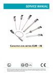
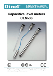
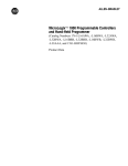
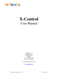
1
INTELLIGENT SERVO DRIVE
FOR BRUSHLESS MOTORS
ISD300R SERIES
- USER MANUAL -
DOCUMENT NUMBER
INTERNAL REFERENCE
EDITION
AUTHOR
DATE
: ISD.MMR.M001
: ISD.142.SP
: 01
: L. DI STEFANO
: 20 OCTOBER 1996
The material in this manual is for informational purposes only and is subject to change without
notice. PRIMA ELECTRONICS S.p.A assumes no responsability for errors or omissions,
neither is any liability assumed for damages resulting from the use of the information
contained herein.
COPYRIGHT 1995 - PRIMA ELECTRONICS S.p.A.
All rights reserved. This document shall not be reproduced, either entirely or in part, without
written authorization.
MO T O R T E C H N O L O G Y L T D
MOTEC HOUSE, CHADKIRK BUSINESS PARK,
STOCKPORT, CHESHIRE SK6 3NE
ENGLAND
TEL: +44 (0)161 217 7100
FAX: +44 (0)161 217 7101
eMAIL: [email protected]
WEB: www.motec.co.uk
DOCUMENT INFORMATION
edition
data
versione
0
7 August 1996
preliminary version
1
20 October 1996
first edition
ISD300R SERIES SERVOAMPLIFIERS
INTELLIGENT SERVO DRIVE ISD300R SERIES
DESCRIPTION
This servoamplifiers is a PWM controlled converter with three-phase power stage
configuration, suitable for driving brushless motors with resolver transducer.
The controller parameters are set by mean of a personal computer (PC) with specialized
software. The PC is connected with a serial interface to the drive.
The converter is built using IGBT transistors for the power stage, has an integrated switching
power supply, integrated controller and protection circuits. The power ground and the signal
ground are galvanically insulated.
The converter generates an encoder simulation output, with two quadrature signals and a 0
marker, with a programmable resolution from 62256 to 1024 pulses/turn.
The reference input is set through a ±10V analog input, all the other input signals are +24V
optically coupled signals. A potential free contact is available for FAULT signal (drive OK ).
The power supply and the control for an electromagnetic brake is incorporated in the drive.
PRODUCT IDENTIFICATION
An identification label is applied on the side of the unit, with the relevant identification data.
When contacting the customer service, please report the Model, Serial number and Part
number, which are indicated on the label.
Intelligent Servo Drive - ISD300R series - User Manual
3
ISD300R SERIES SERVOAMPLIFIERS
MODEL SPECIFICATION
Different models (5 sizes) are available: specification depending on size are shown in the
table below
Ratings
Dim
ISD300T05
ISD300T10
ISD300T15
ISD300T20
ISD300T30
Peak current (trapezoidal)
A
15
25
35
50
60
Rated current (trapezoidal)
A
5
10
15
20
30
Peak current (sinusoidal)
A
10
20
30
40
50
Rated current (sinusoidal)
A
4
8
12
16
24
Power loss at rated current (with
electromechanical brake)
W
79
122
152
195
240
Quiscent power loss (disabled)
W
22
22
22
22
22
Quiscent power loss (with
electromechanica brake)
W
40
40
40
40
40
Efficiency at rated current
%
96
96,5
97
97
97,5
PWM switching frequency
kHz
18
18
18
18
6
Dim
ISD300T05
ISD300T10
ISD300T15
ISD300T20
ISD300T30
kg
3,2
3,2
3,6
3,6
3,6
mm
268x53x230
268x53x230
268x63x230
268x63x230
268x63x230
Mechanical specification
Weight
Dimensions
Intelligent Servo Drive - ISD300R series - User Manual
4
ISD300R SERIES SERVOAMPLIFIERS
TECHNICAL CHARACTERISTICS
Main supply
• Three phase input 230 Vac +10% ÷ -20%
• DC bus nominal voltage 310Vdc
• Internal switching power supply for the control circuitry
• Maximum output voltage to the motor: ≡95% of the DC bus (310Vdc)
• Galvanic insulation between the control circuitry and the power stage
Auxiliary supply
• Auxiliary supply 110-230Vac, 30VA ( optional, selectable through jumpers on the base
board )
The auxiliary supply is needed when the status of the LED indicators and the encoder
simulation function should be maintained active also after removing the main power supply
(220Vac three phase)
When using the auxiliary supply, the input voltage on the main supply can be reduced up to 35
Vac three phase minimum, by eliminating the undervoltage protection via a dedicated jumper
on the base board. (see Jumpers), for usage with low voltage motors.
Enclosure
The drive has a metallic enclosure ( protection grade IP20), suitable for vertical fixing through
two M5 screws on a panel.
WARNING
The drive operates with high voltage, only qualified personnal should be allowed to operate on
the drive. ATTENTION, DANGEROUS VOLTAGES MAY REMAIN ON DRIVE TERMINALS
AND INSIDE THE DRIVE ENCLOSURE UP TO 5 MINUTES AFTER THE POWER HAS BEN
SWITCHED OFF.
Intelligent Servo Drive - ISD300R series - User Manual
5
ISD300R SERIES SERVOAMPLIFIERS
Clamping circuit
• clamp (ballast) circuit short circuit protected.
• DC voltage threshold set at 400Vdc
The braking resistor should be located externally and connnected to the relevant screw
teminals on the front panel.
An intrenal Ixt circuit protects the clamping resistor, limiting the average power to the value
shown in the table below.
Install the appropriate resistor according to the drive model, as shown:
MODEL
R05
R10
R15
R20
R30
CLAMPING
RESISTOR.
33Ω
15Ω
15Ω
10Ω
10Ω
PEAK POWER
(1 second)
4,6 kW
10,6 kW
10,6 kW
16 kW
16 kW
AVERAGE POWER
100 W
240 W
240 W
420 W
420 W
Electromagnetic brake
• the brake can be connected on front panel terminals
• internal power supply for the brake 24Vdc, 0.8A max.
• brake release/lock is automatically operated by the drive
• connections for an optional emergency switch (potential free contact) in series with the
brake are available
Dynamic braking
The drive is capable of braking the motor shorting its windings, and controlling the motor
current at a presettable level
This feature is automatic in case of a fault or drive disable.
This feature can be disabled by connecting to +24V the input 24VSBLO (pin 11 of connector
JP2). If an electromagnetic brake is conected to the drive, the brake is also energized
(released).
Resolver
• reference frequency 12kHz
• reference voltage selectable up to 7.1 Vrms ( 100 mA max )
• required input voltage for sin and cos signals: 2Vrms ± 10%
• digital phase shift compensation between reference and sin/cos inputs (resolver and
cable compensation)
• digital phasing of the resolver with respect to the motor shaft
Intelligent Servo Drive - ISD300R series - User Manual
6
ISD300R SERIES SERVOAMPLIFIERS
Input / Output signals
• digital input for power enable(ENABLE)
15÷24V 20mA
• FAULT output (potential free contact)
24V 1A Max
• power supply output
±15V 50mA
• analog reference input
±10V (differential) 1kΩ impedance
• digital output for encoder emulation : A, B, Z ( RS422 5V differential ) with selectable
resolution
• analog input ( 0÷10V, unipolar, 1kΩ impedance ) for setting the limit of the output
current from 0% ( 0V ) to 100% ( 10V ) of the rated current of the drive. Option.
Protections
• under/overvoltage on DC bus
• short circuit between motor terminals and/or ground
• overcurrent
• resolver connection fault (wire broken) or overvoltage on resolver input signals
• overspeed
• drive overtemperature
• motor overtemperature
In case of intervention of any of the above protection, the FAULT contact is opened. The
protections are cleared by cycling the ENABLE input off and on again.
• Ixt protection circuit
The peak current can be sourced for no more than 0,5 second. After this time the Ixt
protection trips, and the output currrent is automatically limited to the rated current. The
protection do not cause the opening of the FAULT contact.
Ixt protection is automatically reset after 10 seconds, provided that the rated continuous
currrent is set at least 7% less than the Ixt threshold. Otherwise it stays latched until the power
is removed to the unit.
Operating temperature
• Operating temperature: 10°C ÷ 40°. For sizes 15, 20 and 30, forced ventilation is
necessary for operation in the full temperature range at the rated current. (see Cooling
requirements)
• Storage temperature: -10°C ÷ 70°C
Others
• Current loop bandwidth: 3 kHz
• Speed loop bandwidth: 200 Hz
• Linearity better than 0.6%
Intelligent Servo Drive - ISD300R series - User Manual
7
ISD300R SERIES SERVOAMPLIFIERS
Fig. 1.: Printed circuit board layout (base board)
Intelligent Servo Drive - ISD300R series - User Manual
8
ISD300R SERIES SERVOAMPLIFIERS
Fig. 2.: Printed circuit board layout (interface board)
Intelligent Servo Drive - ISD300R series - User Manual
9
CONNECTIONS
CONNECTIONS
The present chapter illustrates the external connections of the ISD300 servoamplifier, both
towards the brushless motor and toward the numerical control.
Fig. 3.: Front Panel
Intelligent Servo Drive - ISD300R series - User Manual
10
CONNECTIONS
Fig. 4.: Wiring diagram
Intelligent Servo Drive - ISD300R series - User Manual
11
CONNECTIONS
MAIN SUPPLY CONNECTIONS
TB3
R
S
line connection - tri-phases 220V
T
PE
screw connection
GND
(frame)
ring or fork terminal
3.5 mm internal diameter
8.0 mm external diameter
When the line transformer has a rated power higher than 6kVA, we recommend to limit the
inrush current as shown:
For further informations about inrush current suppressors, please contact your vendor.
R
R
BHL
FUSE
TRANSFORMER
FUSE
LINE
VOLTAGE
R
FUSE
R = 10 ohm 50W (ARMOURED RESISTORS)
K
K = 220VAC 25A RELAYS
Fig. 5.: Wiring for a line transformer with rated power > 6kVA
Intelligent Servo Drive - ISD300R series - User Manual
12
CONNECTIONS
MOTOR CONNECTIONS
ground
PE
TB2
U
V
GND
(frame)
power
to motor phases
W
screw connection, max. 4mm2 terminals
Note:
an optional noise suppressor ferrite clamp has been foreseen for motor cable
CLAMP RESISTOR CONNECTIONS
TB1
(C2)
(C1)
to external
clamp resistor
screw connection, max. 1.5mm2 terminals
BRAKE AND AUX. CONNECTIONS
TB4
6
5
4
3
2
1
B-
brake brake +
B+
24BRIN brake supply input (24Vdc, 2A)
24VOUT internal brake supply (24Vdc, 0.8A max)
VAUX1
VAUX2
auxiliary power input 110/230Vac
auxiliary power input 110/230Vac
screw connection, max. 1mm2 terminals
Note:
The drive automatically cuts off power and releases the electromechanic brake
when connection between pins 3 and 4 is open
Connect a potential free contact emergency switch between pins 3 and 4, or jumper
them.
Intelligent Servo Drive - ISD300R series - User Manual
13
CONNECTIONS
CONNECTIONS TO THE CONTROL UNIT
JP2
10
1
High density 26 pin
male sub-D connector
19
26
18
9
JP2 - SIGNALS TOWARDS THE CONTROL UNIT
pin
1
2
3
4
5
6
7
8
9
10
11
12
13
14
15
16
17
18
19
20
21
22
23
24
25
26
refernce
FAULT2
+24VOUT
ENABLE
VREF+
+15VOUT
INILIMIT*
FAULT1
24VSBLO
GND24V
INCOM
SHIELD
VREF-15VOUT
GND
ENCA+
ENCAENCB+
ENCBENCZ+
ENCZGND
description
error signal input (relay contact)
auxiliary voltage output ( 24Vdc 0.8A max.)
power enable input
DO NOT CONNECT
velocity (or current) reference input (+)
auxiliary voltage output (50mA max.)
current limit analog input (0÷10V) (option)
DO NOT CONNECT
DO NOT CONNECT
error output (relay contact)
manual brake unlock
auxiliary voltage ground (24Vdc)
ENABLE signal common
cable shield
velocity (or current) reference input (-)
auxiliary voltage output (50mA max.)
analog ground
DO NOT CONNECT
RS422 encoder signal
RS422 encoder signal
RS422 encoder signal
RS422 encoder signal
RS422 encoder signal
RS422 encoder signal
analog ground
DO NOT CONNECT
Note:
signals marked with "*" are optional and supplied on request
Note:
connecting 24VSBLO to +24OUT, the elecromagnetic brake is unlocked and
motor's dynamic braking is disabled.
Intelligent Servo Drive - ISD300R series - User Manual
14
CONNECTIONS
CONNECTIONS TO RESOLVER
JP1
1
6
9
5
Male 9 pin Sub-D connector
JP1 - SIGNALS TO RESOLVER
pin
1
2
3
4
5
6
7
8
9
reference
THERMAL2
n.c
+REFRES
SIN HIGH
COS HIGH
THERMAL1
-REFRES
SIN LOW
COS LOW
description
motor thermal protection*
not connected
positive resolver reference
positive resolver sinus signal
positive resolver cosinus signal
motor thermal protection*
negative resolver reference
negatve resolver sinus signal
negatve resolver cosinus signal
* Connect the thermostatic potential free contact (n.c.), or PTC resistor between these pins
Intelligent Servo Drive - ISD300R series - User Manual
15
CONNECTIONS
CONNECTIONS TO THE PERSONAL COMPUTER (SERIAL LINE)
JPC
1
6
9
5
Female 9 pin Sub-D connector
JPC - SERIAL LINE CONNECTION
pin reference
1
2 RS232-RX
3 RS232-TX
4
5 RS232-GND
6
7
8
9
description
not connected
RS232 receive
RS232 transmit
not connected
Rs232 ground
not connected
not connected
not connected
not connected
Intelligent Servo Drive - ISD300R series - User Manual
16
CONNECTIONS
TABLE OF CONDUCTORS SECTION V.S CONVERTER SIZE
Connector
Function
R05
R10, R15
R20, R30
1,5 mm2
TB1
clamp resistor cable
TB2
motor cable
1,5 mm2
2,5 mm2
4 mm2
TB3
power supply cable
1,5 mm2
2,5 mm2
4 mm2
TB4
brake cable, brake supply
and services
0,5 ÷ 1 mm2
JP1
motor signal cable
0,14 ÷ 0,22 mm2
JP2
control unit signal cable
0,14 mm2
LEDS DESCRIPTION
On the front of the drive 6 LEDs are mouted to display the status
The green LEDs are normally on and their meaning is :
• L6 : 24Vdc supply to the brake
• L5 : 220V tri-phase power on
• L4 : Auxiliary power supply on
• L3 : power enable digital input (ENABLE) on
• L2 : reference enable digital input (ARMO) on
The red LED is normally off and it displays a fault when lit :
• L1 : a fault occurred, power has been cut-off
DL12
DL8
DL7
Front view of LEDs
Intelligent Servo Drive - ISD300R series - User Manual
17
CONNECTIONS
7-SEGMENT DISPLAY
On the front of the drive is located a 7-segment display for status information. The display
shows the actual status of the drive, and in case of a fault, the code of the fault. Depending on
the operating phase the display have different meanings.
Power up
A
1,2,3,4
b
internal self check in progress
internal powerup error
internal self check errors
missing operating code
The powerup condition is indicated by the absence of the decimal dot blinking on the display.
All the errors in this situation are not recoverable, the converter is not operating properly, the
ISD interface on the PC cannot be operated.
Normal operation
After powerup is completed, the decimal dot starts blinking, indicating that the drive has
succesfully completed the self test phase. The ISD interface on the PC works properly.
In this operating condition, three different fault classes are displayed. If more than one fault of
different classes is present, the display shows the fault belonging to the most severe class.
Hardware faults (most severe)
1
2
3
4
5
6
7
n.a.
overvoltage
undervoltage
overcurrent
motor thermal protection
overvoltage of the resolver excitation signal
undervoltage of the resolver excitation signal
All these faults will shut down the power. In case more of a single fault is actually present, the
highest priority fault is displayed (1= highest priority)
Software faults
P (blinking)
wrong data in parameter storage (drive is disabled)
1 (blinking)
Ixt protection. The output current is limited automatically to the preset
Cont Current
level. 10 seconds after the average current is returned below
7% of the threshold,
the previous operating conditions are restored and the
fault indication is cleared
2 (blinking)
n.a.
3 (blinking)
drive thermal protection (drive is disabled)
4 (blinking)
drive overspeed protection (drive is disabled)
I/O related faults (least severe)
=
|-|
|-|
Brake 24V supply is missing (drive is disabled)
Manual brake release (the dynamic braking is disabled)
End of stroke 1 (n.a.)
End of stroke 2 (n.a.)
both End of strokes active (n.a.)
Intelligent Servo Drive - ISD300R series - User Manual
18
CONNECTIONS
TEST POINTS DESCRIPTION
On the front of the drive test points are accessible :
TP4
CURR (istantaneous motor current)
TP3
REF (reference voltage Vref)
TP2
TACHO (speed)
TP1
GND (analog ground)
The voltage on REF test point depends on the Reference amplitude adjust setting. With 100%
amplitude the voltage on the test point is 4V whith 10V input to the drive reference input.
The voltage on TACHO test point depends from the resolution set for the resolver converter,
according to the following table:
RESOLUTION
12 bit
14 bit
16 bit
TACHO
[V/krpm]
0,5
2
8
The voltage on the test point CURR depends on the drive's model, according to the following
table:
Model
CURR
[V/A]
R05
R10
R15
R20
R30
0.3
0.2
0.1
0.082
0.082
Intelligent Servo Drive - ISD300R series - User Manual
19
CONNECTIONS
JUMPERS
The following jumpers on the base board and on the interface board are factory settings, and
do not need to be changed by the user. These jumpers are not accessible and require
opening the enclosure.
The following jumpers are on the base board:
• P0, P1, P9 : used for testing purposes (normally open)
• P2 : undervoltage disable
• P3 : connects GND24V to GND (GND24V is normally floating)
• P4 : used for testing purposes (normally open)
• P5-P6 : set the internal switchmode supply to operate from the auxiliary 110 Vac
supply input
• P7-P8 : set the internal switchmode supply to operate from the 310 Vdc power bus
(these jumpers are mutually exclusive with P5, P6)
The following jumpers are on the interface board:
• JP1, JP2, JP3 : used for testing only (normally closed).
Intelligent Servo Drive - ISD300R series - User Manual
20
ISD-PC INTERFACE
THE ISD-PC INTERFACE
The ISD-PC interface allows to properly setup all drive parameters to fit the final user
application. The interface, running under Windows on a PC, is a friendly and easy to use
environment either for setting application parameters and for verification of the correct
installation during commissioning.
ISD-PC SOFTWARE INSTALLATION
PC requirements
386DX33 or faster cpu, with at last 4M of RAM
Color monitor reccomended
Runs under Windows 3.1, 3.11, Wiindows'95, Windows NT
RS232 serial line (COM1 or COM2) for connecting the drive
Pointing device (mouse or equivalent)
Installation
First copy the ISD.INI file supplied with the ISD-PC to your current Windows directory.
Edit edit the line "port=com1" in the ISD.INI file to set the serial line you are currently using
to connect the drive (COM1 or COM2 are supported)
Attention: DO NOT CHANGE the parameters of the serial line (baud rate, parity etc.)
otherwise it will not be able to connect the drive.
Run the ISD.EXE executable file. The PC_ISD window appears. Execute the Connect
command, from the commands pull-down menu' to connect the drive. The interface is now
active.
Intelligent Servo Drive - ISD300R series - User Manual
21
ISD-PC INTERFACE
USING THE ISD-PC INTERFACE
The ISD-PC interface startup windows is shown in fig.6. Most of the common settings are
shown on the main windows.
I1
P1
I2
I3
I4
I5
I6
P2
P3
P4
S1
L3 L2 L1
T1
T2
I7
T3
Fig 6 : Startup window
On these windows are shown the most important identification data of the converter: Model
(I1), Size (I2), Serial Number (I3), Sw versions (I4, I5) the Configuration (I6) and Motor Poles
(I7). These data cannot be modified by the user, except for the Configuration (I6) and Motor
Poles (I7) fields.
Use the I7 field for storing the name of the configuration file currently in use on the drive. This
will give simple way of identification of the current set of parameters in use on the drive.
Three lamps show the status of Enable (L1), Armo (L2), Fault (L3). Nine smaller smaller red
lamps show the actual faults. An indication of the fault occurred is shown passing on the lamp
icon with the pointing device.
Selector icon (S1), Trimmer icons (T1..T3) and Parameter icons (P1..P4) are used for
parameter setting.
Other windows are available by clicking on the picture of the drive, or through the Block
analyzer command in the Tools pulldown menu (fig. 7)
Intelligent Servo Drive - ISD300R series - User Manual
22
ISD-PC INTERFACE
Ext Reference
Icmd
Position
Speed
Fig 7 : Block diagram window
Clicking the appropriate function block, other windows become available.
Monitoring fields show the current value of drive variables. The value is updated every second
when the ISD-PC interface is connected to the drive.
Intelligent Servo Drive - ISD300R series - User Manual
23
ISD-PC INTERFACE
Ext Reference
T2
Speed
SW1
T4
S2
S3
T1
S4
T5
P2
S5
T3
S6
Icmd
Fig 8 : Command generator window
This window shows a block diagram of the drive command generator block. . Most of the
settings relevant to the speed loop are presented here.
Trimmer icons T4..T5 are shown, selectors S2..S6 are shown and Switch SW1 is shown
Two more windows can be accessed directly from here, clicking the functional block icons:
Power driver window (fig. 4) and Resolver converter window (fig. 5).
Intelligent Servo Drive - ISD300R series - User Manual
24
ISD-PC INTERFACE
Icmd
SW2
SW3
SW4
Irms
Temperature
Current
Fig 9 : Power driver window
In this windows are shown Enable switch SW2, Clear protection switch SW3 and Fault switch
SW4. Enable switch SW2 should always be on to allow enabling the drive. Switches SW3 and
SW4 should always stay off for normal operations.
Intelligent Servo Drive - ISD300R series - User Manual
25
ISD-PC INTERFACE
T8
T6
L4
Speed
Position
T7
S7
T9
Fig 5 : Resolver converter window
This window shows the block diagram of the resolver conversion circuitry on the drive.
In this windows Trimmer icons T6..T9 and selector S7 are shown. Note that Trimmer T8
(Velocity offset) is set in the factory to the correct value and should not be adjusted.
Lamp L4 Sincross is used for Resolver Phase adjust.
Intelligent Servo Drive - ISD300R series - User Manual
26
ISD-PC INTERFACE
Parameters settings
Listed below are the parameter that can be set through the interface. Setting is performed by
clicking on the corresponding icon. A dialog box appears, with either a selection of choices or
a digital trimmer with arrows icons for incrementing or decrementing the value.
After adjusting the value, push the Set button to set the value and the Done to exit the dialog
box.
Warning: parameters are stored in volatile RAM until the configuration is saved in
FLASH EPROM via the Freeze configuration command (see Saving and restoring
settings). If the drive is switched off before saving, all the current configuration is lost.
Startup window
Continuous current (P1) - Coarse/fine setting of the continuous current. This is the current
output level that is automatically set when Ixt protection has tripped.
Peak curent (P2) - Coarse/fine setting of the peak current. Available also in the Command
generator window.
Brake current (P3) - Value of the current set during the dynamic braking.
Ixt threshold (P4) - Threshold for tripping the Ixt protection.
Reference offset compensation (T1) - coarse/fine adjust of the reference offset. Applicable
only in speed mode. Trimmer T3 is available also in the Command generator window.
Speed reference (T2) - coarse/fine adjust of the speed reference. It sets the speed of the
motor when a full scale command is applied to the drive. The full scale command is affected
by the Reference amplitude adjust parameter. The range is 5V(200%) to 10V(100%).
Applicable only in speed mode. Trimmer T2 is available also in the Command generator
window.
Gain adjust (T3) - coarse/fine adjust of the speed loop gain, This trimmer can only increase
the gain. Trimmer T3 is available also in the Command generator window.
Encoder resolution setting (S1) - Four different resolutions are availble, depending on the
resolver resolution selected. The table below shows the min/Max range for each resolution:
RESOLUTION
12
14
16
ENCODER PULSES/TURN
min
max
128
1024
512
4096
2048
16384
These tables are valid for two pole resolvers. If your resolver has a different number of poles,
resolver' s poles number
you must multiply the pulses per turn by
.
2
Intelligent Servo Drive - ISD300R series - User Manual
27
ISD-PC INTERFACE
Motor Poles (I7) - selection of the number of motor poles. 4, 6, 8 poles motor are available.
This setting has no effects until the power is switched off and on again. Remember to freeze
the parameters before switching the drive off.
Resolver converter window
Resolver excitation level (T7) - Value of the excitation signal [Vrms]. Set this value taking into
account the resolver transformer ratio. The input level for Sin, Cos signal should be 2Vrms +10%.
Resolver phase adjust (T6) - Phase adjust of the resolver signals Sin Cos against excitation to
compensate resolver and cabling phase shift. Adjust this trimmer by looking at the L4 lamp.
Increase the value until the lamp toggles. Across the toggle point of the lamp there is the
optimal value. Note: remember that you should issue the Connect command to have the
refresh of the indicators active (see ISD-PC software Installation ).
Resolver resolution (S7) - Selects the resolution of the resolver converter. Note the resolution
affects the maximum tracking speed of the resolver, and therefore the maximum allowed
speed of the motor.
RESOLUTION
12
14
16
RPM MAX
Resolver phase adder (T9) - Adjust the mechanical phasing of the resolver with respect to the
motor shaft. The correct value (degrees) should be determined following the Application note
no. 003, using procedure B for point 3. Resolver positioning. Procedure A do not work with
ISD300 drives.
Command generator window
Armo (SW1) - when cleared to 0 set the input reference to 0. When active allows the input
referenceto be fed to the drive command generator. Its status is shown by L2 lamp.
Reference bandwitdth (S2) - insert a low pass filter on the reference input when low. Should
be set to high when current command is used.
Reference amplitude adjust (T4) - adjust the amplitude of the reference for maximum
command. It allows 100% to 200% regulation, to work with NC which have from ±5V to ±10V
full scale output.
Reference selection (S3) - sets the input reference for the command generator to external,
internal (n.a.) or ramp. If set to ramp adjust the ramp duration with Trimmer T5.
Ramp duration (T5) - Coarse/fine setting of the ramp duration.
Speed loop pole placement (S4) - set the position of the compensation of the PI loop.
Speed loop gain (S5) - set the minimum gain of the speed loop. Set to Low first, than increase
the Gain adjusting trimmer T3. If the gain increase is not sufficient for the application, set S5
to High, and readjust the Gain adjust trimmer T3.
Intelligent Servo Drive - ISD300R series - User Manual
28
ISD-PC INTERFACE
Gain adjust (T3) - coarse/fine adjust of the speed loop gain, This trimmer can only increase
the gain. Trimmer T3 is available also in the Startup window.
Mode select (S6) - Selects operating mode either speed mode or current mode.
Saving and restoring settings
After that the drive is set according to the desired application, parameter should be
permanently stored in the non volatile memory of the drive.
To accomplish this use the Freeze command in the Command pull-down menu. The interface
asks also for a file name to be written on the disk with the parameter set.
It is possible to store the current application paramenters also to a file on the disk, using the
Save as command in the File pull-down menu. The file saved can be stored on the PC disk
for documentation and for initializing new drives with the same parameters.
To accomplish this use the command Open in the File pull-down menu. The selected file is
trasferred to the drive. Remember to Freeze the settings to store them in the non volatile
memory.
In case of a wrong setting of parameters, the default values (factory setting) of the drive
parameter can be recalled though the Restore default command in the Command pull-down
menu
Intelligent Servo Drive - ISD300R series - User Manual
29
ISD-PC INTERFACE
Scope and waveform generator function
This function can be accessed through the Waveform generator command in the Tools pulldown menu.
The scope shows like the front panel of a common digital scope. Buttons are available for
selecting trigger level, slope, trigger position, trigger channel.
The scope starts pushing the Start button. The Trigger lamp (L5) is lit when trigger condition is
met. The Ready lamp (L6) is lit when the buffer is filled. After that, by clicking on the scope
graticule, the selected waveforms are displayed on the screen.
The drive stores internally the samples of 8 channels (2ms sampling time for 1024 samples
buffer). Data are transferred to the screen by clicking on the graticule screen. Displayed
channels are selected through the buttons on top of the graticule: Up to 8 different channels
are displayed.
The waveform and scope window is shown in fig. 6
L5 L6
Fig 6 : Scope and waveform generator window
The waveform generator allows to connect to the drive an internally generated input
waveform, depending on the control mode (speed or current) selected. The user can select
the amplitude, the shape and the period of the waveform. For safety reason, when the
waveform generator is stopped, the drive is disabled. To enable again, use the Enable switch
in the Power driver window of the block analyzer.
Intelligent Servo Drive - ISD300R series - User Manual
30
COOLING REQUIREMENTS
COOLING REQUIREMENTS
NATURAL CONVECTION
In single axis application the unit is used with its lateral heatsink (standard). The following
condition apply:
SIZE
R05
R10
R15
R20
R30
MAX
CONTINUOUS
CURRENT
5A
10A
10A
10A
10A
The above table applies with an ambient temperature of 40°C, and unit mounted vertically with
40 mm free space on both sides and 200 mm above and below to ensure air circulation.
FORCED VENTILATION
The unit has an internal temperature limit switch, set at 80°C. In the following table is shown
the temperature rise ∆T of the heatsink at an ambient temperature of 40°C, using a fan model
PAPST multifan 4314 (119x119 mm):
SIZE
R05
R10
R15
R20
R30
THRESHOLD
80°C
80°C
90°C
90°C
90°C
CURRENT
5A
10A
15A
20A
30A
∆ TEMPERATURE
15°C
20°C
35°C
40°C
40°C
The above table applies with an ambient temperature of 40°C, and unit mounted vertically with
20 mm free space on both sides and 200 mm above and below to ensure air circulation. The
fan should be installed below the unit, with 100mm maximum spacing from the drive. The
required airflow is 100 m³/h.
When using a 24Vdc fan, as the above mentioned PAPST fan, its power supply can be
obtained from the drive, using the brake 24V supply (TB4 connector, pin B+, B-). It should be
checked that if the brake is used, the total current consumption on this power supply
(brake+fan) is less than 0.8 A.
Intelligent Servo Drive - ISD300R series - User Manual
31
DIMENSIONS AND FIXING
DIMENSIONS AND FIXING
As already pointed, the dimensions of the mono-axis applications with lateral heatsink are
different from the multi-axis ones with rear dissipation. The following figures show this two
cases.
LATERAL HEATSINK APPLICATION
(63.00)
Note :
to guarantee an adequate air flow, it is needed to leave a 40 mm clearae
between the units in the multi-axis application.
Intelligent Servo Drive - ISD300R series - User Manual
32
EMC PRESCRIPTION
EMC PRESCRIPTION
FOREWORD
The converter is a product designed to be incorporated in a more complex equipment .
Therefore elettromagnetic compatibility depends by factors that are not totally under control of
the manufacturer but depends on the installation, wiring and grounding of the equipment.
In this manual are given instructions for installation in order to obtain comformity with actual
standards for elettromagnetic compatibility. This information have been collected after a
comprehensive test campaign and their purpose is to make the job of the end user as easy as
possible.
REFERENCE STANDARDS
Generic Standard EN 50081-2 e EN 50082-2 (industrial environment)
•
EN61000-4-2
Electrostatic discharge
•
EN61000-4-4
Electrical fast transient burst
•
EN61000-4-5
Surge immunity (FULL-LIGHTNING)
•
EN61000-4-8
Power frequency magnetic field
•
ENV50140
High frequency elettromagnetic fields
•
ENV50204
Elettromagnetic field at 900 MHz with ON/OFF modulation
•
ENV50141
Radiofrequency
•
EN55011
Radiated and conducted emission
•
EN61800-3
system
Semiconductor power converters for adjustable speed electric drive
Intelligent Servo Drive - ISD300R series - User Manual
33
EMC PRESCRIPTION
INSTALLATION WITH SPECIAL FILTER FOR CONVERTER
CONVERTER
CONTROL
E
UNIT
RESOLVER
D
CLAMP
MAIN
RESISTOR
EMI FILTER
SWITCH
TRANSFORMER
C
A
POWER
SUPPLY
A
A
A
B
FUSES
MOTOR
•
Supply cable(A): no presciption
•
Motor cable(B): to prevent emission of the motor cable is recommended to use shielded
cable. The shielding must be connected to the ground of the converter and to the ground
terminal of the motor.
In this configuration due to the characteristics of the special filter for converter, it is
allowed to use unshielded cable. The cable length must be less or equal 25m.
•
Transformer: must be shielded between primary and secondary windings and its rated
power must be adeguate for equipment requirements.
•
Clamp resistor (C): connected through twisted cable with length less or equal 2m.
•
Motor signal cable (D): shielded cable with length less or equal 25m.
•
Control connections (E): shielded cable with length less or equal 3m.
•
EMI filter: special filter for converter code 2SMPM3338/OC (cable is included).
Conformity
In this configuration the converter is compliant with the regulations referenced above .
Intelligent Servo Drive - ISD300R series - User Manual
34
EMC PRESCRIPTION
INSTALLATION WITHOUT SPECIAL FILTER FOR CONVERTER
CONVERTER
CONTROL
CLAMP
E
UNIT
C
MAIN
SWITCH
D
NET FILTER TRANSFORMER
D
A
A
A
A
A
RESOLVER
B
B
FUSES
MOTOR
•
Supply cable(A): no prescription
•
Motor cable(B): to prevent emission of the motor cable is recomended to use of shielded
cable. The shield must be connect to the converter ground terminal and to the ground
terminal of the motor. The cable length must be less or equal 25m.
•
Transformer: must be shielded between primary and secondary windings and its rated
power must be adeguate for equipment requirements.
•
Clamp resistor (C): connected through twisted cable with length less or equal 2m.
•
Motor signal cable (D): shielded cable with length less or equal 25m.
•
Control connections (E): shielded cable with lenght less or equal 3m.
•
Network filter: Siemens B84143-B XXR with following characteristics:
Nominal voltage: 440/250 Vac, 50/60Hz
Phase number: 3
Temperature range: -25...+40 gradi
Nominal current: range XX = 8-12-16-25-36A for different models
•
Cabinet: All equipments should be installed in metal cabinet closed over all sides.
Conformity
In this configuration the converter is compliant with the regulations referenced above .
Intelligent Servo Drive - ISD300R series - User Manual
35
EMC PRESCRIPTION
INSTALLATION WITHOUT FILTERS
CONTROL UNIT
CONVERTER
CLAMP
RESISTOR
E
C
380VAC
THREE PHASE
A
TRANSFORMER
D
FUSES
A
A
RESOLVER
F
B
MOTOR
F
•
Supply cable(A): no prescription. Install a suppression ferrite KITAGAWA SFC10 (F)
•
Motor cable(B): to prevent emission of the motor cable is recomended to use of shielded
cable. The shield must be connect to the converter ground terminal and to the ground
terminal of the motor. The cable length must be less or equal 25m. Install a suppression
ferrite KITAGAWA SFC10 (F)
•
Transformer: must be shielded between primary and secondary windings and its rated
power must be adeguate for equipment requirements.
•
Clamp resistor (C): connected through twisted cable with length less or equal 2m.
•
Motor signal cable (D): shielded cable with length less or equal 25m.
•
Control connections (E): shielded cable with lenght less or equal 3m.
Conformity
In this configuration the converter is compliant with all the regulation referenced above
regarding immunity (EN50082-2).
In this configuration the converter is not compliant to the emission regulation EN55011
(Emission, Generic standard).
In this configuration the converter is compliant to the product specific regulation EN61800-3
for the class "Restricted distribution"and "Second environment".
Intelligent Servo Drive - ISD300R series - User Manual
36
EMC PRESCRIPTION
Note:
Restricted distribution: the mode of sales distribution in which the manufacturer restricts the
supply of equipment to supplier, customer or users who separatedly or jointly have technical
competence in the EMC requiremets of the application drives.
Second environment: the environment which includes all establishment other than those
directly connected to a low voltage power supply network which supplies building used for
domestic purposes.
It is available on request the documentation of the radiated and conducted emission
measurements to perform adequate action.
If this equipment must work in the first environment please contact the manufacturer.
Intelligent Servo Drive - ISD300R series - User Manual
37
INDEX
INDEX
INTELLIGENT SERVO DRIVE ISD300R SERIES .......................................................................................... 3
DESCRIPTION ................................................................................................................................... 3
PRODUCT IDENTIFICATION ............................................................................................................ 3
MODEL SPECIFICATION................................................................................................................... 4
TECHNICAL CHARACTERISTICS .................................................................................................... 5
Main supply ............................................................................................................................ 5
Auxiliary supply ...................................................................................................................... 5
Enclosure ............................................................................................................................... 5
Clamping circuit...................................................................................................................... 6
Electromagnetic brake ........................................................................................................... 6
Dynamic braking .................................................................................................................... 6
Resolver ................................................................................................................................. 6
Input / Output signals ............................................................................................................. 7
Protections ............................................................................................................................. 7
Operating temperature........................................................................................................... 7
Others .................................................................................................................................... 7
CONNECTIONS ............................................................................................................................................ 10
MAIN SUPPLY CONNECTIONS ...................................................................................................... 12
MOTOR CONNECTIONS................................................................................................................. 13
CLAMP RESISTOR CONNECTIONS .............................................................................................. 13
BRAKE AND AUX. CONNECTIONS ................................................................................................ 13
CONNECTIONS TO THE CONTROL UNIT..................................................................................... 14
CONNECTIONS TO RESOLVER..................................................................................................... 15
CONNECTIONS TO THE PERSONAL COMPUTER (SERIAL LINE) ............................................. 15
TABLE OF CONDUCTORS SECTION V.S CONVERTER SIZE ..................................................... 16
LEDS DESCRIPTION ....................................................................................................................... 16
7-SEGMENT DISPLAY..................................................................................................................... 17
Power up .............................................................................................................................. 17
Normal operation.................................................................................................................. 17
TEST POINTS DESCRIPTION......................................................................................................... 18
JUMPERS......................................................................................................................................... 19
THE ISD-PC INTERFACE ............................................................................................................................. 20
ISD-PC SOFTWARE INSTALLATION ............................................................................................. 20
Intelligent Servo Drive - ISD300R series - User Manual
i
INDEX
PC requirements .................................................................................................................. 20
Installation ............................................................................................................................ 20
USING THE ISD-PC INTERFACE.................................................................................................... 21
Parameters settings ............................................................................................................. 26
Startup window.......................................................................................... 26
Resolver converter window ....................................................................... 27
Command generator window .................................................................... 27
Saving and restoring settings............................................................................................... 28
Scope and waveform generator function ............................................................................. 29
COOLING REQUIREMENTS ........................................................................................................................ 30
NATURAL CONVECTION ................................................................................................................ 30
FORCED VENTILATION .................................................................................................................. 30
DIMENSIONS AND FIXING .......................................................................................................................... 31
LATERAL HEATSINK APPLICATION .............................................................................................. 31
EMC PRESCRIPTION................................................................................................................................... 32
FOREWORD .................................................................................................................................... 32
REFERENCE STANDARDS............................................................................................................. 32
INSTALLATION WITH SPECIAL FILTER FOR CONVERTER........................................................ 33
Conformity............................................................................................................................ 33
INSTALLATION WITHOUT SPECIAL FILTER FOR CONVERTER ................................................ 34
Conformity............................................................................................................................ 34
INSTALLATION WITHOUT FILTERS .............................................................................................. 35
Conformity............................................................................................................................ 35
Intelligent Servo Drive - ISD300R series - User Manual
ii