1
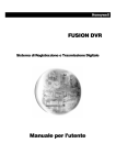
CONTROLLER DMX OPERATOR 200 Manuale d’uso 1 Indice 1. PRIMA DI INIZIARE 1.1 Contenuto...................................................................................................................................... 4 1.2 Istruzioni di disimballaggio............................................................................................................. 4 1.3 Istruzioni di sicurezza.................................................................................................................... 4 2. INTRODUZIONE 2.1 Caratteristiche principali................................................................................................................ 4 2.2 Panoramica generale.................................................................................................................... 5 2.3 Panoramica prodotto (frontale)...................................................................................................... 5 2.4 Panoramica prodotto (retro).......................................................................................................... 6 2.5 Termini comuni.............................................................................................................................. 6 3. ISTRUZIONI D’USO 3.1 AVVIO 3.1.1 Installazione............................................................................................................................... 7 3.1.2 Assegnazione dispositivi............................................................................................................ 7 3.1.3 Canali Pan e Tilt........................................................................................................................ 7 3.1.4 Ripristino di sistema................................................................................................................... 8 3.1.5 Copiare uno Scanner................................................................................................................. 8 3.1.6 Impostare Fade Time................................................................................................................. 8 3.2 FUNZIONAMENTO 3.2.1 Modalità Manuale....................................................................................................................... 9 3.2.2 Rivedere una Scena o un Chase............................................................................................... 9 3.3 PROGRAMMAZIONE 3.3.1 Selezionare Modalità Programmi............................................................................................... 9 3.3.2 Creare una scena...................................................................................................................... 9 3.3.3 Avviare un Programma.............................................................................................................. 10 3.3.4 Verifica di un Programma........................................................................................................... 10 3.3.5 Modificare un Programma.......................................................................................................... 11 3.3.6 Copiare un Programma.............................................................................................................. 11 3.4 OPERARE CON I CHASE 3.4.1 Creare un Chase...................................................................................................................... 11 3.4.2 Avviare un Chase...................................................................................................................... 12 3.4.3 Verifica di un Chase................................................................................................................... 12 3.4.4 Modificare un Chase (Copiare Banco all’interno di un Chase).................................................. 12 3.4.5 Modificare un Chase (Copiare una Scena all’interno di un Chase)........................................... 12 3.4.6 Modificare un Chase (Inserire una Scena all’interno di un Chase)............................................ 13 3.4.7 Cancellare una Scena in un Chase........................................................................................... 13 3.4.8 Cancellare un Chase................................................................................................................. 13 2 3.4.9 Cancellare tutti i Programmi di un Chase................................................................................... 13 3.5 PROGRAMMAZIONE SCENE (STEPS) 3.5.1 Inserire una Scena..................................................................................................................... 14 3.5.2 Copiare una Scena.................................................................................................................... 14 3.5.3 Cancellare una Scena................................................................................................................ 15 3.5.4 Cancellare tutte le Scene........................................................................................................... 15 3.6 PLAYBACK 3.6.1 Modalità Sound.......................................................................................................................... 15 3.6.2 Modalità Auto............................................................................................................................. 15 3.6.3 Blackout..................................................................................................................................... 16 3.7 MIDI................................................................................................................................ 16 4. APPENDICE 4.1 DMX Base.................................................................................................................................... 16 4.2 Collegamento dispositivi................................................................................................................ 17 4.3 Tabella di riferimento rapido DMX dipswitch................................................................................. 18 4.4 Specifiche tecniche........................................................................................................................ 19 3 1. PRIMA DI INZIARE Il presente manuale contiene importanti informazioni sulla sicurezza di installazione e di utilizzo del prodotto. Si prega di leggere e seguire attentamente queste istruzioni e di conservare questo manuale in un luogo sicuro per future consultazioni. 1.1 Contenuto 1) DMX-512 Controller 2) Adattatore d’alimentazione DC 9-12V 500mA, 90V~240V 3) Manuale 4) Lampada LED a collo d’oca 1.2 Istruzioni di disimballaggio Subito dopo aver ricevuto l’apparecchio, aprite attentamente la scatola, controllate il contenuto per verificare che siano presenti tutti i suoi componenti e che sono stati ricevuti in buone condizioni. In caso di segni di manomissione sulla confezione e di segni di danneggiamento dovuti al trasporto informare immediatamente il mittente e conservare il materiale di imballaggio. Nel caso in cui il dispositivo deve essere riinviato al produttore, è importante che il prodotto sia nella scatola d’imballaggio originale. 1.3 Istruzioni di sicurezza Si prega di leggere attentamente queste istruzioni che contengono importanti informazioni sull’installazione, l’uso e la manutenzione. * Si prega di conservare questo manuale per future consultazioni. Se si vende l’apparecchio a un altro utente, assicurarsi di consegnare anche questo libretto di istruzioni. * Verificare sempre di collegarsi con il voltaggio adeguato e che il voltaggio della linea elettrica non sia superiore a quello indicato sul pannello posteriore del dispositivo. * Questo prodotto è destinato solo per uso interno. * Per prevenire il rischio di incendi o scosse elettriche, non esporre l’apparecchio alla pioggia o all’umidità. Assicurarsi che non vi siano materiali infiammabili vicino all’unità durante il funzionamento. * L’unità deve essere installata in un luogo con adeguata ventilazione. Assicurarsi che le prese d’aria non siano ostruite. * Disconnettere sempre dalla corrente prima di sostituire lampade o fusibili e accertarsi di rimontare le stesse lampade. * In caso di problemi di funzionamento, smettere immediatamente di utilizzare l’apparecchio. Non tentate di riparare l’unità da soli. Le riparazioni effettuate da persone inesperte possono causare danni o malfunzionamenti. Si prega di contattare il più vicino centro di assistenza tecnica autorizzato. Utilizzare sempre ricambi dello stesso tipo. * Non collegare il dispositivo a un dimmer pack. * Assicurarsi che il cavo di alimentazione non sia rovinato. * Non scollegare il cavo di alimentazione tirandolo dal filo. * Non utilizzare questo dispositivo se la temperatura ambiente supera i 40°C 2. INTRODUZIONE 2.1 Caratteristiche principali - DMX512/1990 standard - Controlla 12 macchine fino a 16 canali, per un totale di 192 canali - 30 banchi di memoria, ognuno con 8 scene, 6 chase, ciascuno con un massimo di 240 scene - Registra fino a 6 chases con tempo di dissolvenza e velocità regolabile - 16 cursori per il controllo diretto dei canali - Controllo MIDI sui banks, chases e blackout - Microfono incorporato per modalità Music Sound - Modalità Auto controllata da slider FADE TIME - DMX in / out: 3 pin XRL - Lampada a collo d’oca a LED 4 2.2 Panoramica generale Operator 200 permette il controllo di 12 apparecchi composti ciascuno da 16 canali e fino a 240 scene programmabili. Sei banchi di meoria che possono contenere fino a 240 steps composti da scene registrate e in qualsiasi ordine. I programmi possono essere mandati in esecuzione a tempo di musica, attraverso ingresso midi, in modalità auto, o in modalità manuale. Tutti i Chases possono essere eseguiti allo stesso tempo. Sulla superficie troverete vari strumenti di programmazione quali 16 slider per il controllo dei canali, pulsanti per accesso rapido alle scene, e un indicatore display a LED per facilitare la navigazione dei controlli e delle funzioni del menu. 2.3 Panoramica prodotto (frontale) Item Pulsanti o Fader Function 1 Pulsanti selezione Scanner Selezione dispositivo 2 Led indicatori Scanner Indica i dispositivi attualmente selezionati 3 Pulsanti selezione Scene Pulsanti universali utilizzati per la memorizzazione e richiamo di una scena registrata 4 Canali faders Per regolare i valori DMX, Ch 1 ~ 16 possono essere regolati subito dopo aver premuto il pulsante SCANNER relativo 5 Pulsante Program Per entrare nella modalità Programmi 6 Pulsante copia Music/Bank Utilizzato per attivare la modalità musica e come comando di copia durante la programmazione 7 LED Display Display per visualizzare i dati operativi 8 Leds indicatori modalità Indicano modalità di di funzionamento attiva (manuale, musica o auto) 9 Pulsante Bank Up Pulsante per scorrere steps/scene all’interno dei banchi o dei chases 10 Plusante Bank Down Pulsante per scorrere steps/scene all’interno dei banchi o dei chases 11 Pulsante Tap Display Imposta il tempo di movimento di un chase per mezzo del tocco manuale 12 Pulsante Blackout Imposta tutti i valori della operator 200 a zero. 13 Pulsante Midi/ADD Doppia funzione: Attiva il controllo esterno MIDI; nella fase di registrazione conferma e salva. 14 Pulsante Auto/Del Doppia funzione: attiva la modalità atuo; in modalità programmazione cancella. 15 Pulsanti Chaser Chase memory 1 ~ 6 16 Speed fader Regola il tempo di attesa di una scena o uno step all’interno di un chase 17 Fade-Time fader Cross-fader di dissolvenza, imposta l’intervallo di tempo tra due scene in un chase 5 2.4 Panoramica prodotto (retro) Item Pulsante o Fader Function 21 Porta di ingresso MIDI Per il trigger esterno di Banks e Chase utilizzando un dispositivo MIDI 22 Connettore DMX IN/OUT Segnale di controllo DMX 23 DC Ingresso jack Ingresso principale d’alimentazione 24 Presa USB x lampada 25 Interruttore ON/OFF Per accendere o spegnere il controller 2.5 Termini comuni Di seguito i termini comuni utilizzati in questo manuale d’uso. Blackout è uno stato in cui tutti i dispositivi di illuminazione sono impostati a 0, di solito su base temporanea . DMX - 512 è uno standard di protocollo di comunicazione digitale utilizzato in apparecchi di illuminazione. Per maggiori informazioni leggere le sezioni DMX e controllo DMX in appendice. Dispositivo si riferisce allo strumento di illuminazione o altro apparecchio, come un nebulizzatore o dimmer di cui è possibile assumerne il controllo. Programmi sono composti da una serie di scene in sequenza una dopo l’altra. Un programma può essere costruito con una singola scena o con più scene in sequenza. Le Scene sono stati di illuminazione statica. Slider noto anche come slider fader o cursore. Chase può anche essere chiamato programma. Un Chase è costituito da una serie di scene in sequenza una dopo l’altra. Scanner si riferisce ad uno strumento di illuminazione con uno specchio pan e tilt. Nel controller è utilizzato per identificare qualsiasi dispositivo generico controllabile via DMX. MIDI è uno standard per la rirpoduzione di informazioni musicali in formato digitale. L’ingresso MIDI invia informazioni (scene) al controller attraverso un dispositivo esterno es. una tastiera MIDI. Stand Alone si riferisce alla capacità di un apparecchio di funzionare indipendentemente da un controller e di solito in sincronia con la musica attraverso un microfono incorporato. Speed slider determina quanto tempo una scena resta in esecuzione. Shutter è un dispositivo meccanico in apparecchio di illuminazione che consente di otturare il flusso di luce. È spesso utilizzato per regolare i flash della strobo. 6 Patching si riferisce al processo di assegnazione di dispositivi ad un canale DMX. Playbacks possono essere sia scene che chase azionate direttamente dall’utente. Un playback può anche essere considerato come programma di memorizzazione che può essere richiamato durante uno spettacolo. 3. ISTRUZIONI D’USO 3.1 Avvio 3.1.1 INSTALLAZIONE 1) Collegare il controller tramite l’alimentatore in dotazione alla rete elettrica. 2) Collegare il cavo o i cavi DMX ai dispositivi di illuminazione. Per una rapida guida su DMX consultare la sezione DMX nell’appendice di questo manuale. 3.1.2 ASSEGNAZIONE DISPOSITIVI Il controller è programmato per controllare 16 canali DMX per dispositivo, quindi gli apparecchi che si desidera controllare con i tasti corrispondenti sull’unità devono essere distanziati di 16 canali a parte. 1 2 3 4 5 AVVIAMENTO INDIRIZZO DMX DI DEFAULT 1 17 33 49 65 6 81 1, 5, 7 7 8 9 10 11 12 97 113 129 145 161 177 1, 6, 7 1, 5, 6, 7 1, 8 1, 5, 8 1, 6, 8 1, 5, 6, 8 DISPOSITIVO O SCANNER # IMPOSTAZIONI DEI DIPSWITCH CAMBIARE IN “ON POSITION” 1 1, 5 1, 6 1, 5, 6 1, 7 Si prega di fare riferimento al manuale del singolo apparecchio per le istruzioni di indirizzamento DMX. La tabella sopra riportata si riferisce ad un dispositivo standard 9 dip-switch binario. 3.1.3 CANALI PAN E TILT Poiché non tutti i dispositivi di illuminazione sono uguali o condividono le stesse caratteristiche di controllo, il controller permette all’utente di assegnare il canale pan e tilt per ogni singolo apparecchio. Azione : Note : 1) Tenere premuti i tasti PROGRAM e TAPSYNC contemporaneamente 2) Premere un tasto SCANNER che rappresenta il dispositivo o macchina a cui volete riassegnare i faders Tutti i pan / tilt possono essere riassegnati in uscita su un canale DMX diverso. Premere i pulsanti AUTO / DEL per eliminare la modalità di assegnazione del canale. 7 3) Muovere il fader da 1-16 per il quale si vuole selezionare il canale Pan 4) Premere il tasto TAPSYNC DISPLAY per selezionare pan / tilt 5) Muovere il fader da 1-16 per il quale si vuole selezionare il canale Tilt 6) Tenere premuti i tasti PROGRAM e TAPSYNC DISPALY contemporaneamente per uscire e salvare le impostazioni. Tutti i Leds sul mixer lampeggiano. Tutti i pan / tilt possono essere riassegnati in uscita su un canale DMX diverso. 3.1.4 RIPRISTINO DI SISTEMA Attenzione: questa operazione resetta il controller alle impostazioni di fabbrica cancellando tutti i programmi e le impostazioni registrate. Azione : 1) Spegnere l’unità 2) Tenere premuti i tasti BANK UP e AUTO/DEL. 3) Accendere l’unità (continuando a premere i tasti BANK UP e AUTO / DEL). 3.1.5 COPIARE UNO SCANNER Esempio: Copia Scanner 1 in Scanner 2 Azione: Note : 1) Premere e tenere premuto il tasto SCANNER # 1. 2) Tenendo premuto il pulsante # 1 premere il tasto SCANNER # 2. 3) Rilasciare il tasto SCANNER # 1 prima del tasto SCANNER # 2. Per risparmiare tempo, è possibile copiare le impostazioni di un pulsante dello scanner ad un altro. 3.1.6 IMPOSTARE FADE TIME E’ possibile assegnare il fade time solo su alcuni canali del mixer. Questo è importante perché spesso si vuole che i gobos e i colori cambino rapidamente senza influenzare il movimento PAN/TILT della macchina. Generalmente il fade time è impostato su tutti i canali. Azione : Note : 1) Spegnere il controller (tasto OFF) 2) Premere contemporaneamente i tasti BLACKOUT e TAPSYNC DISPLAY 3) Accendere il controller (tasto ON) 4) Premere il tasto TAPSYNC DISPLAY per passare tra le due modalità: Tutti i canali (A) o il canale Pan & Tilt (P) 5) Premere BLACKOUT e TAPSYNC DISPLAY per salvare le impostazioni. Tutti i LEDs lampaeggiano come conferma. A: Tutti i canali P: Solo Pan & Tilt 8 3.2 Funzionamento 3.2.1 MODALITA’ MANUALE La modalità manuale permette il controllo diretto di tutti gli scanner. In questa modalità sarete in grado di spostarli e di cambiarne le impostazioni utilizzando i fader di canale. Azione : Note : 1) Premere ripetutamente il tasto AUTO DEL fino a quando MANUAL LED si accende 2) Selezione un tasto SCANNER. 3) Spostare i fader per modificare gli attributi dei dispositivi. Tasto TAPSYNC DISPLAY: premere per attivare o disattivare l’indicatore di uscita sul display a LED tra i valori DMX (0-255) e percentuale (0-100) Tutte le modifiche apportate mentre si opera in modalità manuale sono temporanee non verranno registrate 3.2.2 RIVEDERE UNA SCENA O UN CHASE Queste istruzioni presuppongono che si siano già registrate una Scena e un Chase sul controller. Altrimenti saltare la sezione e passare alla programmazione. Azione: (rivedere una SCENA) Note: 1) Selezionare uno qualsiasi dei 30 banks premendo il tasto BANK UP/DOWN 2) Selezionare un tasto SCENE (1~8) 3) Muovere i faders per cambiare gli attributi dei dispositivi Assicurarsi di essere ancora in Modalità manuale. Azione: (rivedere un CHASE) Note: 1) Premere uno qualsiasi dei 6 pulsanti CHASE 2) Premere il tasto TAP DISPLAY per visualizzare il numero degli step sul display 3) Premere i pulsanti BANK UP/DOWN per rivedere tutte le scene in un chase. Assicurarsi di essere ancora in Modalità manuale. 3.3 Programmazione Un programma (bank) è una sequenza di scene diverse (o steps) che verranno richiamate una dopo l’altra. Nel controller Operator 200 si possono creare 30 programmi da 8 scene ciascuno. 3.3.1 ACCEDERE ALLA MODALITA’ PROGRAM 1) Premere il tasto PROGRAM fino a quando il LED lampeggia 3.3.2 CREARE UNA SCENA : Una scena è uno stato di illuminazione statica. Le scene sono memorizzate in banchi. Ci sono 30 banchi di memoria nel controller e ogni banco può contenere 8 scene. Il controller può salvare 240 scene in totale. 9 Azione: Note : 1) Premere il tasto PROGRAM fino a quando il LED lampeggia 2) Posizionare gli sliders SPEED e FADE TIME in basso. 3) Selezionare gli SCANNERS che si desidera includere nella vostra scena 4) Attraverso i cursori creare la scena desiderata (impostare posizione, colore , gobos, ecc.) 5) Premere il tasto MIDI/REC 6) Selezionare un BANK (01~30) per modificare, se necessario. 7) Selezionare il pulsante SCENES per memorizzare. 8) Ripetere i passaggi da 3 a 7, se si necessita di avere più scene fino ad un massimo di 8. 9) Per uscire dalla modalità di programmazione, tenere premuto il pulsante PROGRAM Deselezionare Blackout se il LED è acceso. È possibile selezionare più di un dispositivo Ci sono 8 scene disponibili in ogni bank Tutti i LED lampeggiano in segno di conferma. Il display indica ora il numero di scena e il numero di bank utilizzato. 3.3.3 AVVIARE UN PROGRAMMA Azione: Note: 1) Usare i plusanti BANK UP/DOWN per cambiare i bank se necessario 2) Premere il tasto AUTO DEL ripetutamente fino a quando il LED AUTO si accende 3) Regolare la frequenza del programma tramite il fader SPEED e il loop rate tramite il fader FADE TIME. 4) In alternativa si può toccare due volte il tasto TAPSYNC DISPLAY. Il tempo tra due tocchi imposta il tempo tra le scene (fino a 10 minuti). Deselezionare Blackout se il LED è acceso. Definito anche Tap-Sync. 3.3.4 VERIFICA DI UN PROGRAMMA Azione: 1) Premere e tenere premuto il pulsante PROGRAM fino a quando il LED lampeggia 2) Con i plusanti BANK UP/DOWN selezionare PROGRAM bank 3) Premere il tasto SCENES per rivedre le singole scene. 10 3.3.5 MODIFICARE UN PROGRAMMA Le Scene devono essere modificate manualmente. Azione: Note: 1) Premere e tenere premuto il pulsante PROGRAM fino a quando il LED lampeggia. 2) Usare i pulsanti BANK UP/DOWN per cambiare i bank del programma, se necessario. 3) Selezionare il dispositivo desiderato tramite il pulsante SCANNERS 4) Regolare e modificare i valori del dispositivo utilizzando i fader di canal 5) Premere il pulsante MIDI/ADD per preparare il salvataggio 6) Selezionare il pulsante SCENES desiderato per salvare Deselezionare Blackout se il LED è acceso. 3.3.6 COPIARE UN PROGRAMMA Azione: Note: 1) Premere e tenere premuto il pulsante PROGRAM fino a quando il LED lampeggia. 2) Usare i pulsanti BANK UP/DOWN per selezionare il PROGRAMMA (banco) da copiare. 3) Premere il tasto MIDI/ADD per preparare la copia 4) Usare i pulsanti BANK UP/DOWN per selezionare la destinazione del PROGRAMMA (banco) 5) Premere il tasto MUSIC BANK COPY per eseguire la copia. Tutti i LED sul controller lampeggiano. Tutte le 8 scene di un banco di memoria verranno copiate. 3.4 Operare con i Chase Un Chase viene generato utilizzando le scene create in precedenza. Le scene diventano steps che possono essere disposti in qualsiasi ordine si desidera. Si consiglia vivamente di eliminare tutte le sequenze dalla memoria la prima volta che si esegue la programmazione di un chase. Vedere “Elimina tutti Chase” per le istruzioni. 3.4.1 CREARE UN CHASE Un Chase può contenere 240 scene o steps. I termini scene o steps sono usati in modo intercambiabile. Azione: 1) Premere e tenere premuto il pulsante PROGRAM fino a quando il LED lampeggia. 2) Premere il tasto CHASE (1~6) che si desidera programmare 3) Per individuare la scena, se necessario, cambiare BANCO di memoria. 4) Selezionare la SCENA da inserire 5) Premere il tasto MIDI/ADD per memorizzare. 6) Ripetere i punti 3 ~ 5 per aggiungere ulteriori step nel chase. Possono essere registrati fino a 240 steps 7) Premere e tenere premuto il pulsante PROGRAM per salvare il chase. 11 3.4.2 AVVIARE UN CHASE Azione: Note: 1) Premere un tasto CHASE quindi premere il tasto AUTO DEL 2) Regolare la velocità del Chase toccando due volte il pulsante TAPSYNC DISPLAY ad intervallo desiderato. Il tempo tra 2 tocchi imposterà la velocità del chase (fino a 10 minuti) 3.4.3 VERIFICA DI UN CHASE Azione: 1) Premere e tenere premuto il pulsante PROGRAM fino a quando il LED si accende 2) Selezione il CHASE desiderato. 3) Premere il pulsante TAPSYNC DISPLAY per passare agli steps. 4) Esaminare ogni scena/step individualmente utilizzando i tasti BANK UP/DOWN 3.4.4 MODIFICARE UN CHASE (COPIARE UN BANCO IN UN CHASE) Azione: 1) Premere e tenere premuto il pulsante PROGRAM per entrare modalità di programmazione. 2) Premere il tasto CHASE desiderato 3) Selezionare il BANCO da copiare utilizzando i tasti BANK UP/DOWN 4) Premere il pulsante MUSIC/BANK COPY per preparare la copia 5) Premere il tasto MIDI/ADD per copiare il banco di memoria. Tutti i LED lampeggiano 3.4.5 MODIFICARE UN CHASE (COPIARE UNA SCENA IN UN CHASE) Azione: 1) Premere e tenere premuto il pulsante PROGRAM per entrare nella modalità di programmazione. 2) Selezionare il CHASE desiderato. 3) Selezionate il BANCO che contiene la scena da copiare utilizzando i pulsanti BANK UP/DOWN 4) Premere il tasto SCENE corrispondente alla scena da copiare. 5) Premere il tasto MIDI/ADD per copiare la scena. Tutti i LED lampeggiano. 12 3.4.6 MODIFICARE UN CHASE (INSERIRE UNA SCENA IN UN CHASE) Azione: Note: 1) Premere e tenere premuto il pulsante PROGRAM per entrare nella modalità di programmazione. 2) Premere il tasto CHASE desiderato. 3) Premere il tasto TAPSYNC DISPLAY per passare alla visualizzazione degli steps 4) Utilizzare i pulsanti BANK UP/DOWN per scorrere gli steps e individuare il punto di inserimento della nuova scena. Il display visualizza il numero di step 5) Premere il tasto MIDI/ADD per preparare l’inserimento 6) Utilizzare il pulsante BANK UP/DOWN per individuare la scena 7) Premere il tasto SCENE corrispondente alla scena da inserire. 8) Premere il tasto MIDI/ADD per inserire la scena. Tutti i LED lampeggiano. Per inserire unta scena tra LO STEP 05 e 06 utilizzare i pulsanti BANK e premere fino a quando il display visualizza la scritta STEP05. 3.4.7 CANCELLARE UNA SCENA IN UN CHASE Azione: 1) Premere e tenere premuto il pulsante PROGRAM per entrare nella modalità di programmazione. 2) Premere il tasto CHASE desiderato che contiene la scena da cancellare. 3) Premere il tasto DISPLAY TAPSYNC per visualizzare gli steps 4) Selezionare la scena / step da eliminare utilizzando i tasti BANK UP / DOWN 5) Premere AUTO DEL tasto per cancellare lo step / scena. Tutti i LED lampeggiano. 3.4.8 CANCELLARE UN CHASE Azione: 1) Premere e tenere premuto il pulsante PROGRAM per entrare nella modalità di programmazione. 2) Premere il tasto CHASE (1 ~ 6) da cancellare. 3) Tenere premuto il tasto AUTO DEL e il rispettivo pulsante per eliminare il chase. Tutti i LED lampeggiano. 3.4.9 CANCELLARE TUTTI I CHASE ATTENZIONE! Questa procedura comporta la perdita irrevocabile della memoria del chase. Le singole scene e i banks saranno conservati. 13 Azione: 1) Spegnere il controller. 2) Premere e tenere premuto il pulsante BANK DOWN e il tasto AUTO DEL mentre si accende il controller. 3) Tutti i LED lampeggiano. 3.5 PROGRAMMAZIONE DI UNA SCENA (Steps) 3.5.1 INSERIRE UNA SCENA Azione: Note: 1) Premere e tenere premuto il pulsante PROGRAM per entrare nella modalità di programmazione. 2) Premere il tasto CHASE desiderato. 3) Premere il tasto DISPLAY TAPSYNC per visuliazzare sul display gli steps 4) Utilizzare i pulsanti BANK UP / DOWN per muoversi tra gli steps e individuare il punto di inserimento della nuova scena.Il display visualizza il numero di steps. 5) Premere il tasto MIDI / ADD per preparare l’inserimento. 6) Utilizzare il pulsante BANK UP / DOWN per individuare la scena. 7) Premere il tasto SCENE corrispondente alla scena da inserire. 8) Premere il tasto MIDI per inserire la scena. Tutti i LED lampeggiano. Per inserire una scena tra lo Step 05 e 06 navigare utilizzando i pulsanti BANK fino a quando il display visualizza la scritta STEP05. 3.5.2 COPIARE UNA SCENA Azione: 1) Premere e tenere premuto il pulsante PROGRAM per entrare nella modalità di programmazione. 2) Selezionare il BANCO di memoria che contiene la scena da copiare utilizzando i pulsanti BANK UP / DOWN. 3) Premere il tasto SCENE che corrisponde alla scena da copiare. 4) Premere il tasto MIDI / ADD per copiare la scena. 5) Selezionare il BANCO di memoria di destinazione che contiene la scena da registrare utilizzando i pulsanti BANK UP / DOWN. 6) Premere il tasto SCENE desiderato per completare la copia. Tutti i LED lampeggiano. 14 3.5.3 CANCELLARE UNA SCENA Azione : Note: 1) Premere e tenere premuto il pulsante PROGRAM per entrare nella modalità di programmazione. 2) Premere il BANCO che contiene la scena da cancellare usando il tasto BANCK UP/DOWN. 3) Tenere premuto il tasto AUTO DEL. 4) Premer il tasto SCENE corrispondente alla scena da cancellare. Tutti i led lampeggiano Quando si elimina una scena la posizione fisica non viene rimossa. Alla scena sarà impostato il valore 0. 3.5.4 CANCELLARE TUTTE LE SCENE Azione: Note: 1) Premere e tenere premuto il pulsante PROGRAM e il pulsante BANK DOWN mentre si spegne il controller 2) Riaccendere il controller ATTENZIONE! Questo processo è irreversibile. Tutte le scene con i dati verranno impostati a 0. 3.6 Playback 3.6.1 MODALITA’ SOUND Azione: Note: 1) premer il tasto MUSIC BANK COPY finchè non si accende il led Music. 2) Selezionare il BANCO di memoria che si desidera mandare in modalità musicale. 3)Alternativamente si può selezionare un singolo CHASE (1-6), solo alcuni chase o tutti i chase per mandarli in esecuzione sequenziale in ordine di selezione. 4) Può essere variato il tempo di durata per mezzo del fader FADE TIME. Nella modalità audio, i programmi saranno attivati dal suono utilizzando il microfono incorporato. Più chases selezionati si avvieranno nell’ordine selezionato 3.6.2 MODALITA’ AUTO Azione: Note: 1) Premere il pulsante MUSIC BANK COPY fino alla sua accensione 2) Selezionare il BANCO di memoria da eseguire nella modalità AUTO utilizzando i pulsanti BANK UP / DOWN 3) In alternativa è possibile premere un solo pulsante CHASE (1 ~ 6) o più tasti CHASE in sequenza e tutti i chase selezionati si avvierenno in loop nell’ordine selezionato. 4) È possibile regolare il tempo di durata utilizzando il FADE TIME fader. Nella modalità AUTO, velocita e fade time per i programmi in esecuzione possono essere controllati per mezzo dei fader FADE e SPEED. Più chases selezionati si avvieranno nell’ordine selezionato 15 3.6.3 BLACKOUT Il tasto Blackout imposta tutti i valori del controller a 0 come se fosse spento. 3.7 MIDI Il controller risponderà solo ai comandi MIDI impostati sul canale. Tutto il controllo passa ora al controller MIDI. Azione: Note: 1) Premere e tenere premuto il pulsante MIDI/ADD per circa 3 secondi 2) Selezionare il canale di controllo MIDI (1~16) tramite BANK UP/DOWN 3) Premere e tenere premuto il tasto MIDI/ADD per circa 3 secondi per salvare le impostazioni 4) Per rilasciare il controllo MIDI premere qualsiasi altro tasto ad eccezione dei tasti BANK durante la fase 2 Questo è il canale che gestirà i comandi MIDI. MIDI NOTE FUNCTION (TURN ON/OFF) MIDI NOTE FUNCTION (TURN ON/OFF) 00 a 07 Scene 1~8 in BANK 1 88 a 95 Scene 1~8 in BANK 1 08 a 15 Scene 1~8 in BANK 2 96 a 103 Scene 1~8 in BANK 2 16 a 23 Scene 1~8 in BANK 3 104 a 111 Scene 1~8 in BANK 3 24 a 31 Scene 1~8 in BANK 4 112 a 119 Scene 1~8 in BANK 4 32 a 39 Scene 1~8 in BANK 5 120 Chase 1 40 a 47 Scene 1~8 in BANK 6 121 Chase 2 48 a 55 Scene 1~8 in BANK 7 122 Chase 3 56 a 63 Scene 1~8 in BANK 8 123 Chase 4 64 a 71 Scene 1~8 in BANK 9 124 Chase 5 72 a 79 Scene 1~8 in BANK 10 125 Chase 6 80 a 87 Scene 1~8 in BANK 11 126 BLACKOUT 4 APPENDICE 4.1 DMX Base Ci sono 512 canali in una connessione DMX-512. I canali possono essere assegnati in vari modi. Un dispositivo compatibile col DMX 512 necessita di uno o più canali sequenziali. L’utente deve assegnare un indirizzo di partenza sul dispositivo che indica il primo canale occupato nella centralina. Ci sono diversi tipi di apparecchi gestibili tramite DMX e tutti possono variare nel numero totale di canali richiesti (scanner, motorizzati, fari led, dimmer, ecc.) La scelta di un indirizzo iniziale dovrebbe essere pianificata in anticipo. I canali non devono mai sovrapporsi. Se lo fanno, questo si tradurrà in un funzionamento irregolare degli apparecchi il cui indirizzo di partenza è impostato in modo errato. È possibile tuttavia che più apparecchi dello stesso tipo utilizzino lo stesso indirizzo di partenza al fine di ottenere un loro movimento all’unisono. In altre parole, i dispositivi saranno collegati in modalità slave e risponderanno tutti allo stesso modo. Apparecchi DMX sono concepiti per ricevere dati tramite collegamento seriale Daisy Chain. Una connessione 16 Daisy Chain avviena la dove un OUT DATI di un apparecchio è connesso all’ingresso dati del successivo. L’ordine in cui gli apparecchi sono collegati non ha importanza e non incide su come la centralina comunica con ogni apparecchio. L’utilizzo dell’ordine di cablaggio è più semplice e diretto. Collegate le macchine utilizzando cavo schermato due poli XLR maschio XLR femmina. IL collegamento è PIN 1 massa, PIN 2 polo Negativo, PIN 3 polo positivo. 4.2 COLLEGAMENTO DISPOSITIVI Connessione XLR DMX-IN XLR maschio DMX-OUT XLR Femmina 1- Ground 2 - Signal (-) 3 - Signal (+) 1- Ground 2 - Signal (-) 3 - Signal (+) Attenzione: All’ultimo dispositivo della catena DMX si può applicare un terminatore. Saldare una resistenza tra 120 ohm Signal (-) e Signal (+) in un XLR maschio a 3 pin e collegarlo al DMX-output dell’ultimo apparecchio. Nella modalità Controller, all’ultimo dispositivo della catena, l’uscita DMX deve essere collegato un terminatore DMX. Questo impedisce di disturbare e danneggiare i segnali di controllo DMX con il rumore elettrico. Il terminatore DMX è semplicemente un connettore XLR con una resistenza 120W (ohm) collegata tra i pin 2 e 3, che viene poi collegato alla presa di uscita dell’ultimo proiettore della catena. I collegamenti sono illustrati di seguito. Se si desidera collegare diversi controller DMX con diversi XLR output, è necessario utilizzare adattatori-cavi. The transform of the controller line of 3 pins and 5 pins (plug and socket) 17 4.3 Tabella di riferimento rapido DMX Dipswitch Tabella di riferimento rapido degli indirizzi DMX Posizione Dip Switch IMPOSTAZIONI DMX DIP SWITCH 0=OFF 1=ON X=OFF o ON #9 0 0 0 0 0 0 0 0 1 1 1 1 1 1 1 1 #8 0 0 0 0 1 1 1 1 0 0 0 0 1 1 1 1 #7 0 0 1 1 0 0 1 1 0 0 1 1 0 0 1 1 #6 0 1 0 1 0 1 0 1 0 1 0 1 0 1 0 1 32 64 96 128 160 192 224 256 288 320 352 384 416 448 480 #1 #2 #3 #4 #5 0 0 0 0 0 1 0 0 0 0 1 33 65 97 129 161 193 225 257 289 321 353 385 417 449 481 0 1 0 0 0 2 34 66 98 130 162 194 226 258 290 322 354 386 418 450 482 1 1 0 0 0 3 35 67 99 131 163 195 227 259 291 323 355 387 419 451 483 0 0 1 0 0 4 36 68 100 132 164 196 228 260 292 324 356 388 420 452 484 1 0 1 0 0 5 37 69 101 133 165 197 229 261 293 325 357 389 421 453 485 0 1 1 0 0 6 38 70 102 134 166 198 230 262 294 326 358 390 422 454 486 1 1 1 0 0 7 39 71 103 135 167 199 231 263 295 327 359 391 423 455 487 0 0 0 1 0 8 40 72 104 136 168 200 232 264 296 328 360 392 424 456 488 1 0 0 1 0 9 41 73 105 137 169 201 233 265 297 329 361 393 425 457 489 0 1 0 1 0 10 42 74 106 138 170 202 234 266 298 330 362 394 426 458 490 1 1 0 1 0 11 43 75 107 139 171 203 235 267 299 331 363 395 427 459 491 0 0 1 1 0 12 44 76 108 140 172 204 236 268 300 332 364 396 428 460 492 1 0 1 1 0 13 45 77 109 141 173 205 237 269 301 333 365 397 429 461 493 0 1 1 1 0 14 46 78 110 142 174 206 238 270 302 334 366 398 430 462 494 1 1 1 1 1 15 47 79 111 143 175 207 239 271 303 335 367 399 431 463 495 0 0 0 0 1 16 48 80 112 144 176 208 240 272 304 336 368 400 432 464 496 1 0 0 0 1 17 49 81 113 145 177 209 241 273 305 337 369 401 433 465 497 0 1 0 0 1 18 50 82 114 146 178 210 242 274 306 338 370 402 434 466 498 1 1 0 0 1 19 51 83 115 147 179 0 0 1 0 1 20 52 84 116 148 180 212 244 276 308 340 372 404 436 468 500 1 0 1 0 1 21 53 85 117 149 181 213 245 277 309 341 373 405 437 469 501 0 1 1 0 1 22 54 86 118 150 182 214 246 278 310 342 374 406 438 470 502 1 1 1 0 1 23 55 87 119 151 183 215 247 279 0 0 0 1 1 24 56 88 120 152 184 216 248 280 312 344 376 408 440 472 504 1 0 0 1 1 25 57 89 121 153 185 217 249 281 313 345 377 409 441 473 505 0 1 0 1 1 26 58 90 122 154 186 218 250 282 314 346 378 410 442 474 506 1 1 0 1 1 27 59 91 123 155 187 219 251 283 315 347 379 0 0 1 1 1 28 60 92 124 156 188 220 252 284 316 348 380 412 444 476 508 1 0 1 1 1 29 61 93 125 157 189 221 253 285 317 349 381 413 445 477 509 0 1 1 1 1 30 62 94 126 158 190 222 254 286 318 350 382 414 446 478 510 1 1 1 1 1 31 63 95 127 159 191 223 255 287 319 351 383 415 447 479 Posizione Dip Switch 211 243 275 307 339 371 403 435 467 499 Indirizzo DMX 18 311 343 375 407 439 471 503 411 443 475 507 511 4.4 Specifiche tecniche Dimensioni: 520 X 183 X 73 mm Peso: 3.0 Kg Alimentazione DC 9V-12V 500mA min Temperatura ambiente massima: 45 C Data input: 3-pin XLR maschio Data output: 3-pin XLR femmina Configurazione Data pin: pin 1 shield, pin 2 (-), pin 3 (+) Protocollo: DMX-512 USITT 19 User Manual 20 Contents 1. BEFORE YOU BEGIN 1.1 What are included.......................................................................................................................... 23 1.2 Unpacking instructions.................................................................................................................. 23 1.3 Safety instructions......................................................................................................................... 23 2. INSTALLATION 2.1 Features........................................................................................................................................ 23 2.2 General overview........................................................................................................................... 24 2.3 Product overview (front)................................................................................................................ 24 2.4 Product overview (rear panel)....................................................................................................... 25 2.5 Common terms.............................................................................................................................. 25 3. OPERATING INSTRUCTIONS 3.1 SETUP 3.1.1 Setting up the System................................................................................................................ 26 3.1.2 Fixture Addressing..................................................................................................................... 26 3.1.3 Pan and tilt channels.................................................................................................................. 27 3.1.4 Resetting the system................................................................................................................. 27 3.1.5 Copy Scanner............................................................................................................................ 27 3.1.6 Fade Time Assign....................................................................................................................... 27 3.2 OPERATION 3.2.1 Manual Mode............................................................................................................................. 28 3.2.2 Review Scene or Chase............................................................................................................ 28 3.3 PROGRAMMING 3.3.1 Entering program mode............................................................................................................. 28 3.3.2 Create a scene........................................................................................................................... 29 3.3.3 Running a Program.................................................................................................................... 29 3.3.4 Check Program.......................................................................................................................... 29 3.3.5 Editing a Program...................................................................................................................... 29 3.3.6 Copy a Program......................................................................................................................... 30 3.4 CHASE PROGRAMMING 3.4.1 Create a chase........................................................................................................................... 30 3.4.2 Running a Chase....................................................................................................................... 30 3.4.3 Checking a Chase...................................................................................................................... 31 3.4.4 Edit Chase (Copy Bank Into Chase).......................................................................................... 31 3.4.5 Edit Chase (Copy Scene Into Chase)........................................................................................ 31 3.4.6 Edit Chase (Insert Scene Into a Chase).................................................................................... 31 3.4.7 Delete a scene in a Chase......................................................................................................... 32 3.4.8 Delete a Chase........................................................................................................................... 32 21 3.4.9 Delete all Chase Programs......................................................................................................... 32 3.5 SCENE PROGRAMMING (STEPS) 3.5.1 Insert a scene............................................................................................................................ 32 3.5.2 Copy a scene.............................................................................................................................. 33 3.5.3 Delete a scene........................................................................................................................... 33 3.5.4 Delete all scenes........................................................................................................................ 33 3.6 PLAYBACK 3.6.1 Running in Sound-Mode............................................................................................................ 33 3.6.2 Running in Auto-Mode................................................................................................................ 34 3.6.3 Blackout...................................................................................................................................... 34 3.7 MIDI OPERATION.......................................................................................................... 34 4. APPENDIX 4.1 DMX Primer................................................................................................................................... 35 4.2 Fixture Linking............................................................................................................................... 35 4.3 DMX dipswitch quick reference chart........................................................................................... 37 4.4 Technical specifications................................................................................................................. 38 22 1. BEFORE YOU BEGIN This product manual contains important information about the safe installation and use of this projector. Please read and follow these instructions carefully and keep this manual in a safe place for future reference. 1.1 What are included 1) DMX-512 Controller 2) DC 9-12V 500mA, 90V~240V Power Adapter 3) Manual 4) LED gooseneck lamp 1.2 Unpacking Instructions Immediately upon receiving a fixture, carefully unpack the carton, check the contents to ensure that all parts are present, and have been received in good condition. Notify the shipper immediately and retain packing material for inspection if any parts appear damaged from shipping or the carton itself shows signs of mishandling. Save the carton and all packing materials. In the event that a fixture must be returned to the factory, it is important that the fixture be returned in the original factory box and packing. 1.3 Safety Instructions Please read these instructions carefully, which includes important information about the installation, usage and maintenance. * Please keep this User Guide for future consultation. If you sell the unit to another user, be sure that they also receive this instruction booklet. * Always make sure that you are connecting to the proper voltage and that the line voltage you are connecting to is not higher than that stated on decal or rear panel of the fixture. * This product is intended for indoor use only! * To prevent risk of fire or shock, do not expose fixture to rain or moisture. Make sure there are no flammable materials close to the unit while operating. * The unit must be installed in a location with adequate ventilation, at least 50cm from adjacent surfaces. Be sure that no ventilation slots are blocked. * Always disconnect from power source before servicing or replacing lamp or fuse and be sure to replace with same lamp source. * In the event of serious operating problem, stop using the unit immediately. Never try to repair the unit by yourself. Repairs carried out by unskilled people can lead to damage or malfunction. Please contact the nearest authorized technical assistance center. Always use the same type spare parts. * Don t connect the device to a dimmer pack. * Make sure power cord is never crimped or damaged. * Never disconnect power cord by pulling or tugging on the cord. * Do not operate this device under 113 F ambient temperature conditions. 2. INTRODUCTION 2.1 Features * DMX512/1990 Standard * Controls 12 intelligent lights of up to 16 channels, totally 192 channels * 30 banks, each with 8 scenes; 6 chase, each with up to 240 scenes * Record up to 6 chases with fade time and speeds * 16 sliders for direct control of channels * MIDI control over banks, chases and blackout * Built-in microphone for music mode * Auto mode program controlled by fade time sliders * DMX in/out: 3 pin XRL * LED gooseneck lamp * Plastic end housing 23 2.2 General Overview * The Controller is a universal intelligent lighting controller. It allows the control of 12 fixtures composed of 16 channels each and up to 240 programmable scenes. Six chase banks can contain up to 240 steps composed of the saved scenes and in any order. Programs can be triggered by music, midi,automatically or manually. All chases can be executed at the same time. * On the surface you will find various programming tools such as 16 universal channel sliders, quick access scanner and scene buttons, and an LED display indicator for easier navigation of controls and menu functions. 2.3 Product Overview (front) Item Button or Fader Function 1 Scanner select buttons Fixture selection 2 Scanner indicator LEDS Indicates the fixtures currently selected 3 Scene select buttons Universal bump buttons representing scene location for storage and selection 4 Channel faders For adjusting DMX values, Ch 1~16 can be adjusted immediately after pressing the respective scanner select button 5 Program button Used to enter programming mode 6 Music/Bank Copy button Used to activate Music mode and as the copy command during programming 7 LED display window Status window displays pertinent operational data 8 Mode Indicator LEDS Provides operating mode status (manual, music or auto) 9 Bank Up button Function button to traverse Scene/Steps in banks or chases 10 Bank Down button Function button to traverse Scene/Steps in banks or chases 11 Tap Display button Sets the chase speed by tapping, and toggles between values and percentages. 12 Blackout button Sets the shutter or dimmer value of all fixtures to 0 causing all light output to cease 13 Midi/ADD button Activates MIDI external control and also used to confirm the record/ save process 14 Auto/Del button Used to activate Auto mode and as the delete function key during programming 15 Chaser buttons Chase memory 1 ~ 6 16 Speed fader This will adjust the hold time of a scene or a step within a chase 17 Fade-Time fader Also considered a cross-fade, sets the interval time between two scenes in a chase 24 2.4 Product Overview (rear panel) Item Button or Fader Function 21 MIDI input port For external triggering of Banks and Chases using a MIDI device 22 DMX output connector DMX control signal 23 DC Input jack Main power feed 24 USB Lamp socket 25 ON/OFF power switch Turns the controller on and off 2.5 Common Terms The following are common terms used in intelligent light programming. Blackout is a state by where all lighting fixtures light output are set to 0 or off, usually on a temporary basis. DMX-512 is an industry standard digital communication protocol used in entertainment lighting equipment. For more information read Sections DMX Primer and DMX Control Mode in the Appendix. Fixture refers to your lighting instrument or other device such as a fogger or dimmer of which you can control. Programs are a bunch of scenes stacked one after another. It can be programmed as either a single scene or multiple scenes in sequence. Scenes are static lighting states. Sliders also known as faders. Chases can also be called programs. A chase consists of a bunch of scenes stacked one after another. Scanner refers to a lighting instrument with a pan and tilt mirror; however, in the ILS-CON controller it can be used to control any DMX-512 compatible device as a generic fixture. MIDI is a standard for representing musical information in a digital format. A MIDI input would provide external triggering of scenes using midi device such as a midi keyboard. Stand Alone refers to a fixture s ability to function independently of an external controller and usually in sync to music, due to a built in microphone. Fade slider is used to adjust the time between scenes within a chase. Speed slider affects the amount of time a scene will hold its state. It is also considered a wait time. Shutter is a mechanical device in the lighting fixture that allows you to block the lights path. It is often used to lessen the intensity of the light output and to strobe. 25 Patching refers to the process of assigning fixtures a DMX channel or. Playbacks can be either scenes or chases that are directly called to execution by the user. A playback can also be considered program memory that can be recalled during a show. 3. OPERATING INSTRUCTIONS 3.1 Setup 3.1.1 SETTING UP THE SYSTEM 1) Plug the AC to DC power supply to the system back panel and to the mains outlet. 2) Plug in your DMX cable(s) to your intelligent lighting as described in the fixtures respective manual. For a quick Primer on DMX see the DMX Primer section in the Appendix of this manual. 3.1.2 FIXTURE ADDRESSING The Controller is programmed to control 16 channels of DMX per fixture, therefore the fixtures you wish to control with the corresponding buttons on the unit, must be spaced 16 channels apart. FIXTURE OR SCANNER # 1 2 3 4 5 DEFAULT DMX STARTING ADDRESS BINARY DIPSWITCH SETTINGS SWITCH TO THE “ON POSITION” 1 17 33 49 65 1 1, 5 1, 6 1, 5, 6 1, 7 6 81 1, 5, 7 7 8 9 10 11 12 97 113 129 145 161 177 1, 6, 7 1, 5, 6, 7 1, 8 1, 5, 8 1, 6, 8 1, 5, 6, 8 Please refer to your individual fixture s manual for DMX addressing instructions. The table above refers to a standard 9 dipswitch binary configurable device. 26 3.1.3 PAN AND TILT CHANNELS Because not all intelligent lighting fixtures are alike or share the same control attributes, the Controller allows the user to assign the wheel the correct pan and tilt channel for every individual fixture Action : Notes : 1) Press and hold PROGRAM and TAPSYNC different DMX channel. Faders are given a channel buttons together (1) time to access the number and are labeled on the surface of the channel assignment mode. 2) Press a SCANNER button that represents the fixture whose faders you would like to re-assign. All pan/tilt can be reassigned to output on a different DMX channel. Press AUTO/DEL buttons to delete the channel assignment mode. 3) Move one fader of 1-16 channel to select the pan channel. 4) Press the TAPSYNC DISPLAY button to select pan / tilt 5) Move one fader of 1-16 channel to select the tilt channel. 6) press and hold PROGRAM and TAPSYNC DISPALY buttons to exit and save setting. All LEDs will blink. All pan/tilt can be reassigned to output on a different DMX channel. 3.1.4 RESETTING THE SYSTEM Warning: this will reset the controller to its factory defaults. This will erase all programs and settings. Action : 1) Turn off the unit. 2) Press and hold BANK UP and AUTO/DEL. 3) Turn on power to the unit (while still holding BANK UP and AUTO/DEL). 3.1.5 COPY SCANNER Example: Copying Scanner 1 into Scanner 2. Action : Notes : 1) Press and hold SCANNER button # 1. 2) While holding button # 1 press SCANNER button # 2. 3) Release SCANNER button # 1 first before releasing SCANNER button # 2. To save time, you can copy the settings of one Scanner button to another. 3.1.6 FADE TIME ASSIGN You can choose whether the board’s fade time during scene execution is implemented broadly to all output channels or only to the Pan & Tilt movement channels. This is relevant because often you will want gobos and colors to change quickly while not affecting the movement of the light. 27 Action : Notes : 1) Turn OFF the controller. 2) Hold the BLACKOUT and TAPSYNC DISPLAY buttons simultaneously. 3) Turn ON the controller. 4) Press the TAPSYNC DISPLAY button to toggle between the two modes. Either all channels (A) or select channel Pan & Tilt only (P) 5) Press BLACKOUT and TAPSYNC DISPLAY to save settings. All LEDs will blink to confirm. A: All channels P: Only Pan & Tilt 3.2 Operation 3.2.1 MANUAL MODE The manual mode allows direct control of all scanners. You are able to move them and change attributes by using the channel faders. Action : Notes : 1) Press the AUTO DEL button repeatedly until the MANUAL LED is lit. 2) Select a SCANNER button. 3) Move faders to change fixture attributes. TAPSYNC DISPLAY button: Press to toggle the output indicator on the LED display between DMX values (0-255) and percentage (0-100) All changes made while in Manual Mode are temporary and will not be recorded. 3.2.2 REVIEW SCENE OR CHASE This instruction assumes that you have already recorded scenes and chases on the controller. Other wise skip section and go to programming. Action : (SCENE Review) Notes : 1) Select any one of the 30 banks by pressing the BANK UP/DOWN buttons. 2) Select a SCENE button (1~8) to review. 3) Move wheel and faders to change fixture attributes. Make sure you are still in MANUAL Mode. Action : (CHASE Review) Notes : 1) Press any one of the 6 CHASE buttons. 2) Press the TAP DISPLAY button to view the step number on the display. 3) Press the BANK UP/DOWN buttons review all scenes in the chase. Make sure you are still in MANUAL Mode. 3.3 Programming A program (bank) is a sequence of different scenes (or steps) that will be called up one after another. In the controller 30 programs can be created of 8 scenes in each. 3.3.1 ENTERING PROGRAM MODE 1) Press the PROGRAM button until the LED blinks. 28 3.3.2 CREATE A SCENE : A scene is a static lighting state. Scenes are stored in banks. There are 30 bank memories on the controller and each bank can hold 8 scene memories. The controller can save 240 scenes total. Action : Notes : 1) Press the PROGRAM button until the LED blinks. 2) Position SPEED and FADE TIME sliders all the way down. 3) Select the SCANNERS you wish to include in your scene 4) Compose a look by moving the sliders and wheel. 5) Tap MIDI/REC button. 6) Choose a BANK (01~30) to change if necessary. 7) Select a SCENES button to store. 8) Repeat steps 3 through 7 as necessary. 8 scenes can be recorded in a Program. 9) To exit program mode, hold the PROGRAM button. Deselect Blackout if LED is lit. You can select more than one fixture. There are 8 scenes available in every bank. All LEDs will flash to confirm. The LED display will now indicate the Scene number and Bank number used. 3.3.3 RUNNING A PROGRAM Action : Notes : 1) Use BANK UP/DOWN buttons to change banks if necessary. 2) Press the AUTO DEL button repeatedly until the AUTO LED turns on. 3) Adjust the PROGRAM speed via the SPEED fader and the loop rate via the FADE TIME fader. 4) Alternatively you can tap the TAPSYNC DISPLAY button twice. The time between two taps sets the time between SCENES (up to 10 minutes). Deselect Blackout if LED is lit. Also called a Tap-Sync. 3.3.4 CHECK PROGRAM Action : 1) Press and hold the PROGRAM button until the LED blinks. 2) Use the BANK UP/DOWN buttons to select the PROGRAM bank to review. 3) Press the buttons SCENES to review each scene individually. 3.3.5 EDITING A PROGRAM Scenes will need to be modified manually. Action : Notes : 1) Press and hold the PROGRAM button until the LED blinks. 2) Use BANK UP/DOWN buttons to change Program banks if necessary. 3) Select the desired fixture via the SCANNERS button. 4) Adjust and change fixture attributes using the channel faders and wheel. 5) Press the MIDI/ADD button to prepare the save. 6)Select the desired SCENES button to save. Deselect Blackout if LED is lit. 29 3.3.6 COPY A PROGRAM Action : Notes : 1) Press and hold the PROGRAM button until the LED blinks. 2) Use BANK UP/DOWN buttons to select the PROGRAM bank you will copy. 3) Press the MIDI/ADD button to prepare the copy. 4) Use BANK UP/DOWN buttons to select the destination PROGRAM bank. 5) Press the MUSIC BANK COPY button to execute the copy. All LEDs on the controller will blink. All 8 scenes in a Program bank will be copied. 3.4 Chase Programming A chase is created by using previously created scenes. Scenes become steps in a chase and can be arranged in any order you choose. It is highly recommended that prior to programming chases for the first time; you delete all chases from memory. See “Delete All Chases” for instructions. 3.4.1 CREATE A CHASE A Chase can contain 240 scenes as steps. The term steps and scenes are used interchangeably. Action : 1) Press the PROGRAM button until the LED blinks. 2) Press the CHASE (1~6) button you wish to program. 3) Change BANK if necessary to locate a scene. 4) Select the SCENE to insert. 5) Tap the MIDI/ADD button to store. 6) Repeat steps 3 ~ 5 to add additional steps in the chase. Up to 240 steps can be recorded. 7) Press and hold the PROGRAM button to save the chase 3.4.2 RUNNING A CHASE Action : Notes : 1) Press a CHASE button then press the AUTO DEL button. 2) Adjust the Chase speed by tapping the TAPSYNC DISPLAY button twice at a rate of your choosing. The time between 2 taps will set the chase speed (up to 10 minutes) 30 3.4.3 CHECKING A CHASE Action : 1) Press and hold the PROGRAM button until the LED is lit. 2) Select the desired CHASE button. 3) Press the TAPSYNC DISPLAY button to switch the LED display to steps. 4) Review each scene/step individually by using the BANK UP/DOWN buttons. 3.4.4 EDIT CHASE (COPY BANK INTO CHASE) Action : 1) Press and hold the PROGRAM button to enter programming mode. 2) Press the desired CHASE button. 3) Select the BANK to be copied using the BANK UP/ DOWN buttons. 4) Press MUSIC/BANK COPY button to prepare copy. 5) Press MIDI/ADD button to copy the bank. All LEDs will blink. 3.4.5 EDIT CHASE (COPY SCENE INTO CHASE) Action : 1) Press and hold the PROGRAM button to enter programming mode. 2) Press the desired CHASE button. 3) Select the BANK that contains the scene to be copied using the BANK UP/DOWN buttons. 4) Press the SCENE button that corresponds to the scene to be copied. 5) Press MIDI/ADD button to copy the scene. All LEDs will blink. 3.4.6 EDIT CHASE (INSERT SCENE INTO A CHASE) Action : Notes : 1) Press and hold the PROGRAM button to enter programming mode. 2) Press the desired CHASE button. 3) Press the TAPSYNC DISPLAY to switch the LED display to steps view. 4) Use the BANK UP/DOWN buttons to navigate steps and locate the insert point of the new scene. The display will read the step number. 5) Press MIDI/ADD button to prepare the insert. 6) Use the BANK UP/DOWN button to locate the SCENE. 7) Press the SCENE button that corresponds to the scene to be inserted. 8) Press MIDI/ADD button to insert the scene. All LEDs will blink. To insert a scene between Steps 05 and 06 navigate using BANK buttons until the display reads STEP05. 31 3.4.7 DELETE A SCENE IN A CHASE Action : 1) Press and hold the PROGRAM button to enter programming mode. 2) Press the desired CHASE button that contains The scene to be deleted. 3) Press the TAPSYNC DISPLAY button to switch the LED display to steps. 4) Select the scene/step to be deleted using the BANK UP/DOWN buttons 5) Press AUTO DEL button to delete the step/scene. All LEDs will blink. 3.4.8 DELETE A CHASE Action : 1) Press and hold the PROGRAM button to enter programming mode. 2) Press the CHASE button (1~6) to be deleted. 3) Press and hold AUTO DEL button and the respective button to delete the chase. All LEDs will blink. 3.4.9 DELETE ALL CHASE PROGRAMS CAUTION! This procedure will result in irrevocable loss of chase step memory. The individual scenes and program banks will be preserved. Action : 1) Turn OFF controller. 2) Press and hold the BANK DOWN button and the AUTO DEL button while turning ON the controller. 3) All LEDs will blink. 3.5 Scene Programming (Steps) 3.5.1 INSERT A SCENE Action : Notes : 1) Press and hold the PROGRAM button to enter programming mode. 2) Press the desired CHASE button. 3) Press the TAPSYNC DISPLAY to switch the LED display to steps view. 4) Use the BANK UP/DOWN buttons to navigate steps and locate the insert point of the new scene. The display will read the step number. 5) Press MIDI/ADD button to prepare the insert. 6) Use the BANK UP/DOWN button to locate the SCENE. 7) Press the SCENE button that corresponds to the scene to be inserted. 8) Press MIDI button to insert the scene. All LEDs will blink. To insert a scene between Steps 05 and 06 navigate using BANK buttons until the display reads STEP05. 32 3.5.2 COPY A SCENE Action : 1) Press and hold the PROGRAM button to enter programming mode. 2) Select the BANK that contains the scene to be copied using the BANK UP/DOWN buttons. 3) Press the SCENE button that corresponds to the scene to be copied. 4) Press MIDI/ADD button to copy the scene. 5) Select the destination BANK that contains the scene memory to record onto using the BANK UP/ DOWN buttons. 6) Press the desired SCENE button to complete copy. All LEDs will blink. 3.5.3 DELETE A SCENE Action : Notes : 1) Press and hold the PROGRAM button to enter programming mode. 2) Select the BANK that contains the scene to be deleted by using the BANK UP/DOWN buttons. 3) Press and hold the AUTO DEL button. 4) Press the SCENE button that corresponds to the scene you want to delete. All LEDs will blink. When deleting a scene the physical location is not removed, however, all 192 DMX channels available to the scene will be set to value 0. 3.5.3 DELETE A SCENE Action : Notes : 1) Press and hold the PROGRAM button and the BANK DOWN button while turning off power to the controller. 2) Turn the controller back on. CAUTION! This process is irreversible. All scenes with data will be set to 0. 3.6 Playback 3.6.1 RUNNING IN SOUND-MODE Action : Notes : 1) Press the MUSIC BANK COPY button until the turns on. 2) Select the program BANK to run in soundactive mode using the BANK UP/DOWN buttons. 3) Alternatively you can press a single CHASE button (1~6) or several CHASE buttons in sequence and all selected chases will loop in the order selected. 4) You can adjust the duration time using the FADE TIME fader. In the Sound mode, programs will be triggered by the sound using its built-in microphone. Multiple chases selected will loop and run in the order originally selected. 33 3.6.2 RUNNING IN AUTO-MODE Action : Notes : 1) Press the MUSIC BANK COPY button until the turns on. 2) Select the program BANK to run in soundactive mode using the BANK UP/DOWN buttons. 3) Alternatively you can press a single CHASE button (1~6) or several CHASE buttons in sequence and all selected chases will loop in the order selected. 4) You can adjust the duration time using the FADE TIME fader. In the Sound mode, programs will be triggered by the sound using its built-in microphone. Multiple chases selected will loop and run in the order originally selected. 3.6.3 BLACKOUT The Blackout button brings all lighting output to 0 or off. 3.7 Midi Operation The controller will only respond to MIDI commands on the MIDI channel which it is set to full stop. All MIDI control is performed using Note on commands. All other MIDI instructions are ignored. To stop a chase, send the blackout on note. Action : Notes : 1)Press and hold the MIDI/ADD button for about 3 seconds. 2) Select the MIDI control channel (1~16) via the BANK UP/DOWN buttons to set. 3) Press and hold the MIDI/ADD button for 3 seconds to save settings. 4) To release MIDI control, press any other button except the BANK buttons during step 2. This is the Channel that the controller will receive MIDI note commands. MIDI NOTE FUNCTION (TURN ON/OFF) MIDI NOTE FUNCTION (TURN ON/OFF) 00 to 07 Scenes 1~8 in BANK 1 88 to 95 Scenes 1~8 in BANK 1 08 to 15 Scenes 1~8 in BANK 2 96 to 103 Scenes 1~8 in BANK 2 16 to 23 Scenes 1~8 in BANK 3 104 to 111 Scenes 1~8 in BANK 3 24 to 31 Scenes 1~8 in BANK 4 112 to 119 Scenes 1~8 in BANK 4 32 to 39 Scenes 1~8 in BANK 5 120 Chase 1 40 to 47 Scenes 1~8 in BANK 6 121 Chase 2 48 to 55 Scenes 1~8 in BANK 7 122 Chase 3 56 to 63 Scenes 1~8 in BANK 8 123 Chase 4 64 to 71 Scenes 1~8 in BANK 9 124 Chase 5 72 to 79 Scenes 1~8 in BANK 10 125 Chase 6 80 to 87 Scenes 1~8 in BANK 11 126 BLACKOUT 34 4 APPENDIX 4.1 DMX Primer There are 512 channels in a DMX-512 connection. Channels may be assigned in any manner. A fixture capable of receiving DMX 512 will require one or a number of sequential channels. The user must assign a starting address on the fixture that indicates the first channel reserved in the controller. There are many different types of DMX controllable fixtures and they all may vary in the total number of channels required. Choosing a start address should be planned in advance. Channels should never overlap. If they do, this will result in erratic operation of the fixtures whose starting address is set incorrectly. You can however, control multiple fixtures of the same type using the same starting address as long as the intended result is that of unison movement or operation. In other words, the fixtures will be slaved together and all respond exactly the same. DMX fixtures are designed to receive data through a serial Daisy Chain. A Daisy Chain connection is where the DATA OUT of one fixture connects to the DATA IN of the next fixture. The order in which the fixtures are connected is not important and has no effect on how a controller communicates to each fixture. Use an order that provides for the easiest and most direct cabling. Connect fixtures using shielded two conductor twisted pair cable with three pin XLR male to female connectors. The shield connection is pin 1, while pin 2 is Data Negative (S-) and pin 3 is Data positive (S+). 4.2 FIXTURE LINKING Occupation of the XLR-connection DMX-OUTPUT XLR mounting-socket: DMX-OUTPUT XLR mounting-plug: 1- Ground 2 - Signal (-) 3 - Signal (+) 1- Ground 2 - Signal (-) 3 - Signal (+) Caution: At the last fixture, the DMX-cable has to be terminated with a terminator. Solder a 120 ohm resistor between Signal (-) and Signal (+) into a 3-pin XLR-plug and plug it in the DMX-output of the last fixture. In the Controller mode, at the last fixture in the chain, the DMX output has to be connected with a DMX terminator. This prevents electrical noise from disturbing and corrupting the DMX control signals. The DMX terminator is simply an XLR connector with a 120W (ohm) resistor connected across pins 2 and 3, which is then plugged into the output socket on the last projector in the chain. The connections are illustrated below. 35 If you wish to connect DMX-controllers with other XLR-outputs, you need to use adapter-cables. The transform of the controller line of 3 pins and 5 pins (plug and socket) 36 4.3 DMX Dipswitch Quick Reference Chart DMX Address Quick Reference Chart Dip Switch Position DMX DIP SWITCH SET 0=OFF 1=ON X=OFF or ON #9 0 0 0 0 0 0 0 0 1 1 1 1 1 1 1 1 #8 0 0 0 0 1 1 1 1 0 0 0 0 1 1 1 1 #7 0 0 1 1 0 0 1 1 0 0 1 1 0 0 1 1 #6 0 1 0 1 0 1 0 1 0 1 0 1 0 1 0 1 32 64 96 128 160 192 224 256 288 320 352 384 416 448 480 #1 #2 #3 #4 #5 0 0 0 0 0 1 0 0 0 0 1 33 65 97 129 161 193 225 257 289 321 353 385 417 449 481 0 1 0 0 0 2 34 66 98 130 162 194 226 258 290 322 354 386 418 450 482 1 1 0 0 0 3 35 67 99 131 163 195 227 259 291 323 355 387 419 451 483 0 0 1 0 0 4 36 68 100 132 164 196 228 260 292 324 356 388 420 452 484 1 0 1 0 0 5 37 69 101 133 165 197 229 261 293 325 357 389 421 453 485 0 1 1 0 0 6 38 70 102 134 166 198 230 262 294 326 358 390 422 454 486 1 1 1 0 0 7 39 71 103 135 167 199 231 263 295 327 359 391 423 455 487 0 0 0 1 0 8 40 72 104 136 168 200 232 264 296 328 360 392 424 456 488 1 0 0 1 0 9 41 73 105 137 169 201 233 265 297 329 361 393 425 457 489 0 1 0 1 0 10 42 74 106 138 170 202 234 266 298 330 362 394 426 458 490 1 1 0 1 0 11 43 75 107 139 171 203 235 267 299 331 363 395 427 459 491 0 0 1 1 0 12 44 76 108 140 172 204 236 268 300 332 364 396 428 460 492 1 0 1 1 0 13 45 77 109 141 173 205 237 269 301 333 365 397 429 461 493 0 1 1 1 0 14 46 78 110 142 174 206 238 270 302 334 366 398 430 462 494 1 1 1 1 1 15 47 79 111 143 175 207 239 271 303 335 367 399 431 463 495 0 0 0 0 1 16 48 80 112 144 176 208 240 272 304 336 368 400 432 464 496 1 0 0 0 1 17 49 81 113 145 177 209 241 273 305 337 369 401 433 465 497 0 1 0 0 1 18 50 82 114 146 178 210 242 274 306 338 370 402 434 466 498 1 1 0 0 1 19 51 83 115 147 179 0 0 1 0 1 20 52 84 116 148 180 212 244 276 308 340 372 404 436 468 500 1 0 1 0 1 21 53 85 117 149 181 213 245 277 309 341 373 405 437 469 501 0 1 1 0 1 22 54 86 118 150 182 214 246 278 310 342 374 406 438 470 502 1 1 1 0 1 23 55 87 119 151 183 215 247 279 0 0 0 1 1 24 56 88 120 152 184 216 248 280 312 344 376 408 440 472 504 1 0 0 1 1 25 57 89 121 153 185 217 249 281 313 345 377 409 441 473 505 0 1 0 1 1 26 58 90 122 154 186 218 250 282 314 346 378 410 442 474 506 1 1 0 1 1 27 59 91 123 155 187 219 251 283 315 347 379 0 0 1 1 1 28 60 92 124 156 188 220 252 284 316 348 380 412 444 476 508 1 0 1 1 1 29 61 93 125 157 189 221 253 285 317 349 381 413 445 477 509 0 1 1 1 1 30 62 94 126 158 190 222 254 286 318 350 382 414 446 478 510 1 1 1 1 1 31 63 95 127 159 191 223 255 287 319 351 383 415 447 479 Dip Switch Position 211 243 275 307 339 371 403 435 467 499 DMX Address 37 311 343 375 407 439 471 503 411 443 475 507 511 4.4 Technical Specifications Dimensions: 520 X183 X73 mm Weight: 3.0 Kg Operating Range: DC 9V-12V 500mA min Maximum ambient temperature: 45 C Data input: locking 3-pin XLR male socket Data output: locking 3-pin XLR female socket Data pin configuration: pin 1 shield, pin 2 (-), pin 3 (+) Protocols: DMX-512 USITT 38