1
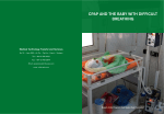
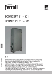
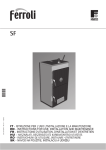
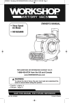
cod. 3540I815 — 07/2011 (Rev. 00) , SUN P7 - P12 IT - ISTRUZIONE PER L’USO L'INSTALLAZIONE E LA MANUTENZIONE EN - INSTRUCTIONS FOR USE, INSTALLATION AND MAINTENANCE CS - NÁVOD K POUŽITÍ, INSTALACI A ÚDRŽBċ RO - INSTRUCğIUNI DE UTILIZARE, INSTALARE ùI ÎNTRETINERE RU - ɊɍɄɈȼɈȾɋɌȼɈ ɉɈ ɗɄɋɉɅɍȺɌȺɐɂɂ, ɆɈɇɌȺɀɍ ɂ ɌȿɏɈȻɋɅɍɀɂȼȺɇɂɘ SK - NÁVOD NA POUŽITIE, INŠTALÁCI A ÚDRŽBU SUN P7 - P12 IT Legenda Rif. fig. 1 Metodo A Metodo B e C 1. AVVERTENZE GENERALI 1 Pulsante impostazione giorno/ora • 2 Pulsante selezione modalità funzionamento 3 Pulsante Override • • • • • • • • Leggere ed osservare attentamente le avvertenze contenute in questo libretto di istruzioni. Dopo l’installazione della caldaia, informare l’utilizzatore sul funzionamento e consegnargli il presente manuale che costituisce parte integrante ed essenziale del prodotto e deve essere conservato con cura per ogni ulteriore consultazione. L’installazione e la manutenzione devono essere effettuate in ottemperanza alle norme vigenti, secondo le istruzioni del costruttore e devono essere eseguite da personale professionalmente qualificato. È vietato ogni intervento su organi di regolazione sigillati. Un’errata installazione o una cattiva manutenzione possono causare danni a persone, animali o cose. È esclusa qualsiasi responsabilità del costruttore per i danni causati da errori nell’installazione e nell’uso e comunque per inosservanza delle istruzioni. Prima di effettuare qualsiasi operazione di pulizia o di manutenzione, disinserire l’apparecchio dalla rete di alimentazione agendo sull’interruttore dell’impianto e/o attraverso gli appositi organi di intercettazione. In caso di guasto e/o cattivo funzionamento dell’apparecchio, disattivarlo, astenendosi da qualsiasi tentativo di riparazione o di intervento diretto. Rivolgersi esclusivamente a personale professionalmente qualificato. L’eventuale riparazionesostituzione dei prodotti dovrà essere effettuata solamente da personale professionalmente qualificato utilizzando esclusivamente ricambi originali. Il mancato rispetto di quanto sopra può compromettere la sicurezza dell’apparecchio. Questo apparecchio dovrà essere destinato solo all’uso per il quale è stato espressamente previsto. Ogni altro uso è da considerarsi improprio e quindi pericoloso. Gli elementi dell’imballaggio non devono essere lasciati alla portata di bambini in quanto potenziali fonti di pericolo. Le immagini riportate nel presente manuale sono una rappresentazione semplificata del prodotto. In questa rappresentazione possono esserci lievi e non significative differenze con il prodotto fornito. 2. ISTRUZIONI D’USO 4 Pulsante - 5 Pulsante programmazione 6 Pulsante + 7 Display 8 Simbolo funzionamento Automatico 9 Simbolo Menù programmazione 10 Simbolo richiesta accensione bruciatore 11 12 Non utilizato Simbolo multifunzione: •in funzione Automatico, indica quando l'orologio programmatore è nella fascia di richiesta •se non è stato selezionato il funzionamento Automatico, indica il funzionamento Manuale On 13 Simbolo Override 14 Simbolo disattivato Simbolo Giorno 15 Simbolo disattivato Simbolo Impostazione 16 Temperatura sensore riscaldamento Ora corrente 17 Simbolo °C Minuti correnti 18 Attuale potenza bruciatore 1 = Minima 5 = Massima O/FH = Durante Preventilazione/Post ventilazione 6 = Durante Postventilazione2 Giorno della settimana 19 Indicazione bruciatore acceso Indicazioni durante il funzionamento 2.1 Presentazione Gentile Cliente, La ringraziamo di aver scelto SUN P7 - P12, un bruciatore FERROLI di concezione avanzata, tecnologia all’avanguardia, elevata affidabilità e qualità costruttiva. SUN P7 - P12 è un bruciatore di pellet, la cui elevata compattezza e disegno originali lo rendono adatto all’impiego sulla maggior parte delle caldaie per combustibile solido oggi presenti sul mercato. La cura nel progetto e nella produzione industriale ha permesso di ottenere una macchina ben equilibrata, dagli alti rendimenti, bassi tenori di emissioni CO ed NOx ed una fiamma molto silenziosa. 2.2 Pannello comandi Visualizzazione display Il display visualizzerà informazioni diverse in base alla metodologia di funzionamento impostata. Le metodologie di funzionamento sono 3: • • • A = Gestione bruciatore (Default setting) B = Gestione bruciatore (Secondo orologio interno o contatto) C = Gestione bruciatore (Secondo orologio interno e contatto) fig. 2 - Metodo A La richiesta d'accensione (generata alla chiusura del contatto sui morsetti 7-8 (vedi fig. 17), in condizioni di default setting) è indicata dall'attivazione del simbolo radiatore (part. 10 - fig. 1). Display 1 2 3 8 9 10 11 12 fig. 3 - Metodo B e C 13 2.3 Accensione 14 15 4 5 6 7 16 17 18 19 fig. 1 - Pannello comandi fig. 4 - Metodo A fig. 5 - Metodo B e C Fornire alimentazione elettrica all'apparecchio: • Durante i primi 10 secondi il display visualizza: - • • 2 IT La versione software dell’interfaccia utente e della centralina (solo metodo A) “nOCU” (solo metodo B e C) Il bruciatore esegue una pre-ventilazione della camera di combustione. Al termine di questo tempo, il bruciatore sarà pronto per il funzionamento. cod. 3540I815 - 07/2011 (Rev. 00) SUN P7 - P12 2.4 Regolazioni Menù parametri Impostazione orologio (solo metodo B e C) L’accesso al menù parametri avviene premendo il pulsante programmazione “M” (part. 2 - fig. 1) per 5 secondi. Viene visualizzato il parametro “u01”: identificato dalla scritta SET 01. Premendo il pulsante “P” (part. 5 - fig. 1) sarà possibile scorrere la lista dei parametri. 1. 2. 3. 4. Premere il pulsante impostazione giorno/ora (part. 1 - fig. 1). Sul display (part. 7 - fig. 1), le icone OROLOGIO e DAY lampeggiano: impostare il giorno corrente della settimana attraverso i tasti + e - (part. 4 e 6 - fig. 1), considerando che 1=lunedì, 7=domenica. Confermare il giorno attraverso la pressione del pulsante impostazione giorno/ ora (part. 1 - fig. 1). Sul display (part. 7 - fig. 1), le due cifre dell’ORA ATTUALE e l’icona OROLOGIO lampeggiano: impostare l’ora esatta attraverso i tasti + e - (part. 4 e 6 - fig. 1), da 00 a 23. Confermare l’ora attraverso la pressione del pulsante impostazione giorno/ora (part. 1 - fig. 1). Sul display (part. 7 - fig. 1), le due cifre dei MINUTI ATTUALI e l’icona OROLOGIO lampeggiano: impostare i minuti esatti attraverso i tasti + e - (part. 4 e 6 - fig. 1), da 00 a 59. Confermare i minuti attraverso la pressione del pulsante impostazione giorno/ora (part. 1 - fig. 1). Funzionamento Riscaldamento Automatico, Manuale On, Manuale Off Premendo il pulsante selezione modalità funzionamento (part. 2 - fig. 1) è possibile impostare il: 1. 2. 3. In Funzionamento Automatico, sul display (part. 7 - fig. 1), è visualizzata l’icona OROLOGIO. La richiesta d’attivazione e di disattivazione del bruciatore dipende dal programma settimanale impostato. Nella fascia oraria di richiesta, sul display (part. 7 - fig. 1), è visualizzata anche l’icona ON. In Funzionamento Manuale On, sul display (part. 7 - fig. 1), è visualizzata solo l’icona ON. Il bruciatore risulta sempre in richiesta. Il programma settimanale impostato è by-passato. A In Funzionamento Manuale Off, sul display (part. 7 - fig. 1), non è visualizzata né l’icona ON, né l’icona OROLOGIO. Il bruciatore risulta spento. Il programma settimanale impostato è by-passato. A 08:30 12:00 12:00 16:30 22:30 • • • • Attenzione: verificare metodologia funzionamento bruciatore (vedi sez. 4.1) Range SUN P7 - P12 30 - 80 °C 80°C Potenza massima bruciatore 1-5 u03 3 Metodologia funzionamento bruciatore (vedi par 3.1) 0-2 0 Per uscire dal menù, premere il pulsante "selezione modalità funzionamento - M" (Part.2 – fig. 1) per 5 secondi. Menù parametri service L’accesso al menù parametri avviene premendo il pulsante programmazione “P” (part. 5 - fig. 1) per 10 secondi. Viene visualizzato il parametro “t01”: identificato dalla scritta SET 01. Premendo il pulsante “P” (part. 5 - fig. 1) sarà possibile scorrere la lista dei parametri. Utilizzare i tasti + e - (part. 4 e 6 fig. 1) per modificare l’inizio della 2st fascia oraria di ON; esempio 12:30Premere il pulsante Programmazione "P" (part. 5 - fig. 1) Utilizzare i tasti + e - (part. 4 e 6 fig. 1) per modificare l’inizio della 2st fascia oraria di OFF; esempio 14:00Premere il pulsante Programmazione "P" (part. 5 - fig. 1) Range Default/ SUN P7 SUN P12 t01 Funzione carica pellet 0=Disabilitata 1=Abilitata 0=Disabilitata 0=Disabilitata t02 Sonda mandata 0=Disabilitata 1=Abilitata 1=Abilitata 1=Abilitata t03 Setpoint ventilatore in Accen- 0-200 Pa sione 51 Pa 51 Pa t04 Tempo attivazione coclea in Accensione 0-100 (1=4 secondi) 8 8 t05 Timer calcolo regolazione (Solo con funzionamento bruciatore con Sonda mandata Modulante) 0-100 secondi 5 secondi 5 secondi t06 Timer funzione Rampa 0-100 secondi 100 secondi 100 secondi t07 0-50 secondi Periodo (Tempo attivazione+disattivazione) coclea a regime (da Potenza 1 a Potenza 5) 15 secondi 12 secondi t08 Setpoint ventilatore a Potenza 1 0-200 Pa 51 Pa 51 Pa t09 Tempo attivazione coclea a Potenza 1 0-100 (100=10 secondi) 28 38 t10 Setpoint ventilatore a Potenza 2 0-200 Pa 74 Pa 70 Pa t11 Tempo attivazione coclea a Potenza 2 0-100 (100=10 secondi) 38 40 t12 Setpoint ventilatore a Potenza 3 0-200 Pa 120 Pa 100 Pa t13 Tempo attivazione coclea a Potenza 3 0-100 (100=10 secondi) 46 45 t14 Setpoint ventilatore a Potenza 4 0-200 Pa 150 Pa 120 Pa t15 Tempo attivazione coclea a Potenza 4 0-100 (100=10 secondi) 53 60 t16 Setpoint ventilatore a Potenza 5 0-200 Pa 170 Pa 155 Pa t17 Tempo attivazione coclea a Potenza 5 0-100 (100=10 secondi) 56 65 t18 Selezione funzionamento bruciatore (Solo con Sonda Mandata) 0=On/Off 1=Modulante 0=On/Off 0=On/Off t19 Tempo Post ventilazione2 0-100 (100=10 secondi) 99 99 t20 Tensione fotoresistenza 0-30 (50 = 5Vdc) -- -- 16:30 e Radiatore lampeggianti, ON, 5 • 9. u02 12:00 e Radiatore lampeggianti, 4 • 8. Utilizzare i tasti + e - (part. 4 e 6 fig. 1) per modificare l’inizio della 1st fascia oraria di OFF; esempio 09:00Premere il pulsante Programmazione "P" (part. 5 - fig. 1) 12:00 e Radiatore lampeggianti, ON, 3 • 7. Utilizzare i tasti + e - (part. 4 e 6 fig. 1) per modificare l’inizio della 1st fascia oraria di ON; esempio 06:00Premere il pulsante Programmazione "P" (part. 5 - fig. 1) 08:30 e Radiatore lampeggianti, 2 • 6. Day 1 e Radiatore lampeggianti: programmazione riscaldamento del Lunedì Day 2 e Radiatore lampeggianti: programmazione riscaldamento del Martedì Day 3 e Radiatore lampeggianti: programmazione riscaldamento del Mercoledì Day 4 e Radiatore lampeggianti: programmazione riscaldamento del Giovedì Day 5 e Radiatore lampeggianti: programmazione riscaldamento del Venerdì Day 6 e Radiatore lampeggianti: programmazione riscaldamento del Sabato Day 7 e Radiatore lampeggianti: programmazione riscaldamento del Domenica Day 15 e Radiatore lampeggianti: programmazione riscaldamento periodo Lunedì - Venerdì Day 67 e Radiatore lampeggianti: programmazione riscaldamento periodo Sabato - Domenica Day 16 e Radiatore lampeggianti: programmazione riscaldamento periodo Lunedì - Sabato Day 17 e Radiatore lampeggianti: programmazione riscaldamento periodo Lunedì - Domenica Day 17 e Radiatore lampeggianti: non utilizzato Premere il pulsante Programmazione "P" (part. 5 - fig. 1): 06:30 e Radiatore lampeggianti, ON, 1 • 5. Regolazione setpoint mandata Premere il pulsante Programmazione "P" (part. 5 - fig. 1) Selezionare il giorno da programmare attraverso i tasti + e - (part. 4 e 6 - fig. 1): • • • • • • • • 3. 4. Descrizione u01 Parametri Descrizione Modifica del programma settimanale (solo metodo B e C) 1. 2. Parametri Tabella. 2 Il programma settimanale è pre-impostato con 3 fasce orarie di ON e 3 fasce orarie di OFF: uguali per ogni giorno della settimana. Nella fascia oraria di richiesta, sul display (part. 7 - fig. 1), è visualizzata l’icona ON. A Tabella. 1 Per modificare il valore di un parametro basterà premere i tasti + e - (part. 4 e 6 – fig. 1): la modifica verrà salvata automaticamente. Una volta modificato il parametro, è necessario attendere 3 secondi: il dato lampeggia e viene salvato. Programma settimanale pre-impostato 06:30 Per modificare il valore di un parametro basterà premere i tasti + e - (part. 4 e 6 - fig. 1): la modifica verrà salvata automaticamente. Una volta modificato il parametro, è necessario attendere 3 secondi: il dato lampeggia e viene salvato. Utilizzare i tasti + e - (part. 4 e 6 fig. 1) per modificare l’inizio della 3st fascia oraria di ON; esempio 16:00Premere il pulsante Programmazione "P" (part. 5 - fig. 1) Per uscire dal menù, premere il pulsante programmazione “P” (part. 5 - fig. 1) per 10 secondi. 22:30 e Radiatore lampeggianti, 6 • Utilizzare i tasti + e - (part. 4 e 6 fig. 1) per modificare l’inizio della 3st fascia oraria di OFF; esempio 23:30Premere il pulsante Programmazione "P" (part. 5 - fig. 1) 10. Ripetendo la procedura appena descritta, si può programmare la 4st fascia oraria di ON e la 4st fascia oraria di OFF. 11. Premere il pulsante Programmazione "P" (part. 5 - fig. 1) per 3 secondi, si esce dalla modalità programmazione. , cod. 3540I815 - 07/2011 (Rev. 00) IT 3 SUN P7 - P12 2.5 Istruzioni per il funzionamento Istruzioni di montaggio del bruciatore a pellet SUN P7 - P12 nella caldaia SFL Il funzionamento del bruciatore, una volta installato e regolato correttamente, è completamente automatico e non richiede di fatto alcun comando da parte dell’utente. In caso di mancanza di combustibile o anomalie il bruciatore si arresta e va in blocco. Si consiglia di provvedere al rifornimento del combustibile prima del suo totale esaurimento per evitare il funzionamento irregolare del bruciatore. Sono disponibili dei kit opzionali per l'uso del bruciatore a pellet con caldaie SFL. Per l’installazione fare riferimento alle istruzioni contenute negli stessi kit. Fare attenzione che il locale in cui è installato il bruciatore, oltre che privo di oggetti o materiali infiammabili, gas corrosivi o sostanze volatili, non sia polveroso. La polvere, infatti, richiamata dal ventilatore, aderisce alle pale della girante e ne riduce la portata d’aria oppure causa l’ostruzione del disco di stabilità fiamma pregiudicandone l’efficienza. B A termine del montaggio del kit in caldaia, montare il bruciatore. Fissare il boccaglio “L” con le viti “M” e il bruciatore con il dado “N”. Collegare il cavo “E” ai morsetti 11 e 12, e il cavo “T” al sensore “V”. Fissare il cofano “P” al corpo bruciatore con le viti “R” e il particolare “S” al bruciatore. Non permettere che il bruciatore sia manomesso da persone inesperte o da bambini. E Regolazione potenza massima (param. u02) in funzione della caldaia S Valore parametro SUN P7 Potenza - kW SUN P12 Potenza - kW 1 14 30 2 20 36 3 25 41 4 30 48 5 34 55 V T L M N 3. INSTALLAZIONE R 3.1 Disposizioni generali Questo apparecchio deve essere destinato solo all’uso per il quale è stato espressamente previsto. Questo apparecchio può essere applicato, compatibilmente alle sue caratteristiche e prestazioni ed alla sua potenzialità termica, generatori di calore per combustibili solidi. Ogni altro uso deve considerarsi improprio e quindi pericoloso. Non è consentito né aprire o manomettere i componenti dell’apparecchio, ad esclusione delle sole parti previste nella manutenzione, né è consentito modificare l’apparecchio per alterarne le prestazioni o la destinazione d’uso. M P Se il bruciatore viene completato con optionals, kits o accessori si dovranno utilizzare solo prodotti originali. B L’INSTALLAZIONE E LA TARATURA DEL BRUCIATORE DEVE ESSERE EFFETTUATA SOLTANTO DA PERSONALE SPECIALIZZATO E DI SICURA QUALIFICAZIONE, OTTEMPERANDO A TUTTE LE ISTRUZIONI RIPORTATE NEL PRESENTE MANUALE TECNICO, ALLE DISPOSIZIONI DI LEGGE VIGENTI, ALLE PRESCRIZIONI DI NORMA NAZIONALE ED EVENTUALI NORMATIVE LOCALI E SECONDO LE REGOLE DELLA BUONA TECNICA. fig. 6 Inserire il tubo di alimentazione motorizzato “Y” nel serbatoio raccolta pellet “X” ed effettuare il collegamento coclea-bruciatore in modo tale che il tubo flessibile “W” non subisca deformazioni e/o pieghe. E’ necessario rispettare la quota indicata nella fig. 11. Regolare il bruciatore come previsto dal relativo manuale istruzioni in particolare, impostare il parametro u02 sulla centraliana del bruciatore come riportato nella tabella. 3.2 Installazione in caldaia Luogo di installazione Il locale entro il quale caldaia e bruciatore sono installati deve avere le aperture verso l’esterno secondo quanto prescritto dalle norme vigenti. Se nello stesso locale vi sono più bruciatori o aspiratori che possono funzionare assieme, le aperture di aereazione devono essere dimensionate per il funzionamento contemporaneo di tutti gli apparecchi. Modello 3 4 5 6 7 kW 24.9 33.4 41 48 55 Potenza termica nominale kW 22 30 36 42 48 Parametro u02 2 5 3 4 5 Portata termica nominale Il luogo di installazione deve essere privo di oggetti o materiali infiammabili, gas corrosivi polveri o sostanze volatili che, richiamate dal ventilatore possano ostruire i condotti interni del bruciatore o la testa di combustione. L’ambiente deve essere asciutto e non esposto a pioggia, neve o gelo. Fissare il bruciatore alla porta. Effettuare i collegamenti elettrici come riportato al cap. 5 (schema elettrico). Nel caso il bruciatore venga installato in una caldaia SUN P7 - P12, utilizzare l’apposito kit di trasformazione. Inserire la sonda di temperatura contenuta nel kit nella guaina sul corpo della caldaia in ghisa ed effettuare i relativi collegamenti elettrici. B IL BRUCIATORE E’ STATO PROGETTATO PER FUNZIONARE SU GENERATORE DI CALORE CON CAMERA DI COMBUSTIONE IN DEPRESSIONE. IL CONTENITORE DEL PELLETS DEVE ESSERE POSIZIONATO IN MODO CHE IL TUBO FLESSIBILE DI COLLEGAMENTO COCLEA/BRUCIATORE NON SUBISCA DEFORMAZIONI E/O PIEGHE. OK fig. 7 4 IT cod. 3540I815 - 07/2011 (Rev. 00) SUN P7 - P12 W min. 600 Y X OK fig. 8 fig. 11 3.3 Collegamenti elettrici Il bruciatore è dotato di una morsettiera multipolare per gli allacciamenti elettrici; far riferimento allo schema elettrico nel capitolo “4 Caratteristiche e dati tecnici” per le connessioni. I collegamenti da effettuare a cura dell’installatore sono: • • • • Linea di alimentazione Contatto di richiesta Collegamento motore coclea Collegamento sonda temperatura La lunghezza dei cavi di collegamento deve permettere l’apertura del bruciatore ed eventualmente del portellone della caldaia. In caso di guasto al cavo di alimentazione del bruciatore, la sua sostituzione va fatta solo da persona abilitata. Il bruciatore va collegato ad una linea elettrica monofase, 230 Volt-50Hz. B fig. 9 Far verificare da personale professionalmente qualificato l’efficenza e l’adeguatezza dell’impianto di terra, il costruttore non è responsabile per eventuali danni causati dalla mancanza di messa a terra dell’impianto. Far verificare inoltre che l’impianto elettrico sia adeguato alla potenza massima assorbita dall’apparecchio, indicata in targhetta dati caldaia. È importante rispettare le polarità (LINEA: cavo marrone / NEUTRO: cavo blu / TERRA: cavo giallo-verde) negli allacciamenti alla linea elettrica. 3.4 Alimentazione combustibile Disposizioni generali Il bruciatore deve essere alimentato dal tipo di combustibile per il quale è predisposto, come indicato sulla targa dell’apparecchio e nella tabella dati tecnici al sez. 5.3 di questo manuale. Consigliamo l’utente di utilizzare pellet di buona qualità, in quanto quello di bassa qualità determina basse rese caloriche, alto contenuto di ceneri con conseguenti interventi di pulizia frequenti, possibilità di usura precoce dei componenti del bruciatore esposti al fuoco, intasamento della coclea e del bruciatore dovuti ad eccesso di segatura sciolte, blocchi di funzionamento dovuti a sedimentazione di materiali non combustibile all’interno del bruciatore. Per distinguere il pellet di qualità è bene seguire alcuni accorgimenti: • • • Deve essere costituito da cilindri di diametro costante ed avere una superficie liscia e lucida. Controllare che sulle etichette siano riportati gli estremi delle certificazioni di qualità Controllare che le confezioni siano integre in modo che il pellet non assorba umidità. Carica pellet È possibile attivare la carica del pellet entro 40 minuti dopo aver alimentato elettricamente il bruciatore. fig. 10 Entro questo tempo, il sistema mette a disposizione 3 tentativi da 5 minuti, durante i quali viene attivata solamente la coclea. Durante la carica del pellet non risulta possibile accendere il bruciatore. Sequenza: 1. 2. 3. 4. , Fornire alimentazione elettrica al bruciatore. Attendere il termine della fase di pre-ventilazione. Premere il pulsante programmazione “P” (part. 5 - fig. 1) per 5 secondi. - Viene visualizzato il parametro “tø1”: identificato dalla scritta SET 01. - Impostare il parametro a 1 per avviare il primo tentativo da 5 minuti. In qualsiasi momento è possibile terminarlo, ponendo il parametro 0. - Nel caso in cui il primo tentativo non sia stato sufficente, ripetere la sequenza precedente portando il parametro a 0 e poi a 1: sia per il secondo che per il terzo tentativo di carica. Per poter eseguire altri 3 tentativi, togliere e ridare alimentazione elettrica all’apparecchio. cod. 3540I815 - 07/2011 (Rev. 00) IT 5 SUN P7 - P12 4. SERVIZIO E MANUTENZIONE Accensione del bruciatore Tutte le operazioni di regolazione, messa in servizio e manutenzione devono essere effettuate da Personale Qualificato e di sicura qualificazione, in conformità alle norme vigenti. Il personale della nostra organizzazione di vendita e del Servizio Tecnico Assistenza Clienti di Zona è a vostra disposizione per ogni ulteriore informazione. • FERROLI declina ogni responsabilità per danni a cose e/o persone derivanti dalla manomissione dell’apparecchio da parte di persone non qualificate e non autorizzate. Taratura del bruciatore 4.1 Metodologia funzionamento bruciatore • • 1. Per gestire l’accensione del bruciatore sono previste 3 metodologie: 2. 3. A - Gestione Bruciatore (default setting) La richiesta d’accensione del bruciatore viene attivata esclusivamente alla chiusura del contatto sui morsetti 7-8 (vedi fig. 17). A 4. L’orologio ed il programma settimanale impostato sono by-passati: si può anche non impostare l’ ora corretta. Fornire alimentazione elettrica, chiudendo l’interruttore generale a monte del bruciatore. Per riempire la coclea di pellets vedi sez. 3.4. Chiudere la linea dei termostati (caldaia/ambiente). Collegare un analizzatore di combustione all’uscita della caldaia e lasciare funzionare il bruciatore a pieno regime per 30 minuti; verificare nel frattempo la funzionalità del condotto di evacuazione dei fumi. ACCERTARSI CHE LA CAMERA DI COMBUSTIONE SIA IN DEPRESSIONE Verificare la combustione alla potenza massima del bruciatore (regolata in base alla potenza nominale della caldaia). Parametri della combustione: • • B - Gestione Bruciatore (Secondo Orologio interno o Contatto) O2 compreso tra 5% e il 9% CO compreso tra 150 e 1000 ppm Per la taratura del bruciatore, variare il setpoint ventilatore modificando il relativo parametro (vedi paragrafo “Menù parametri service” e tabella 2 al cap. 2.4). Il valore CO è influenzato dalla qualità del pellet, dalla quantità di sporco presente nella testa di combustione e dal tiraggio della caldaia. La richiesta d’accensione del bruciatore viene attivata dall’Orologio (durante il Funzionamento Riscaldamento Automatico in Fascia ON oppure in Funzionamento Riscaldamento Manuale ON) O alla chiusura del contatto sui morsetti 7-8 (vedi fig. 17). A gramma settimanale impostato di default. Si rende necessario impostare l’Orologio ed eventualmente modificare il pro- Se si vuole far funzionare il bruciatore in modo MODULANTE, è necessario modificare il parametro “T18” e quindi seguire i punti 5 e 6 sotto riportati. Verificare gli altri step del bruciatore riducendo il valore del parametro u02 sino a 1 (vedi paragrafo “Menù parametri service” e tabella 1 al cap. 2.4). Riportare il parametro u02 al valore corretto. C -Gestione Bruciatore (Secondo Orologio interno e Contatto) 5. La richiesta d’accensione del bruciatore viene attivata dall’Orologio (durante il Funzionamento Riscaldamento Automatico in Fascia ON oppure in Funzionamento Riscaldamento Manuale ON) e se è chiuso il contatto sui morsetti 7-8 (vedi fig. 17). 6. A A sporcarsi in funzione della qualità del pellet o a causa di una cattiva regolazione Si rende necessario impostare l’Orologio ed eventualmente modificare il programma settimanale impostato di default. 4.3 Manutenzione Verificare periodicamente la pulizia delle parti del bruciatore che tenderanno a del bruciatore. La selezione A, B o C avviene dal menù utente dell’Orologio. Premere il pulsante selezione modalità funzionamento “M” (part. 2 - fig. 1) per 5 secondi. Premere 2 volte il pulsante Programmazione “P” (part. 5 - fig. 1). Il bruciatore richiede una manutenzione periodica, con cadenza almeno annuale, che deve essere eseguita da personale abilitato. Le operazioni basilari da effettuare sono: Viene visualizzato il parametro n° 3: identificato dalla scritta SET 03. • controllo e pulizia della parti interne del bruciartore e caldaia come indicato nei paragrafi successivi; analisi completa della combustione (dopo funzionamento a regime per almeno 10 minuti) e verifica delle corrette tarature; Impostare a 00 per modo A, 01 per modo B, 02 per modo C attraverso i tasti + e - (part. 4 e 6 - fig. 1). • Una volta selezionata la metodologia è necessario attendere 3 secondi: il dato lampeggia e viene salvato. Per uscire dal menù, premere il pulsante selezione modalità funzionamento “M” (part. 2 - fig. 1) per 5 secondi. Apertura cofano e smontaggio del bruciatore 4.2 Messa in servizio Verifiche da eseguire alla prima accensione, e dopo tutte le operazioni di manutenzione che abbiano comportato la disconnessione degli impianti o un intervento su organi di sicurezza o parti del bruciatore: Prima di accendere il bruciatore • • • • • • Controllare che il bruciatore sia fissato correttamente in caldaia con le tarature preliminari indicate precedentemente. Accertarsi che caldaia ed impianto siano stati riempiti d’acqua od olio diatermico, che le valvole del circuito idraulico siano aperte e che il condotto di evacuazione fumi sia libero e correttamente dimensionato. Verificare la chiusura della porta caldaia, in modo che la fiamma si generi solamente all’interno della camera di combustione. Verificare il corretto posizionamento della coclea e del tubo flessibile di collegamento al bruciatore. Riempire il serbatoio di pellet. Verificare il corretto posizionamento e collegamento della sonda temperatura. B Prima di effettuare qualsiasi operazione di pulizia o controllo all’interno del bruciatore, togliere l’alimentazione elettrica al bruciatore agendo sull’interruttore generale dell’impianto. Per l’apertura Svitare le viti (A) e togliere il cofano (B). I componenti interni, motore, serranda, ecc. sono direttamente accessibili. Per lo smontaggio Svitare le viti (A) e togliere il cofano (B), svitare il dado (C) e scollegare il corpo, svitare le viti di fissaggio (D) ed estrarre il boccaglio (E). A Verificare che la griglia (part. 1 fig. 12) sia pulita. E D C A 1 B fig. 13 fig. 12 - Griglia bruciatore 6 IT cod. 3540I815 - 07/2011 (Rev. 00) SUN P7 - P12 Verifiche su parti e componenti 5. CARATTERISTICHE E DATI TECNICI Ventilatore 5.1 Dimensioni Verificare che all’interno del ventilatore e sulle pale della girante non vi sia accumulo di polvere: riduce la portata d’aria e causa, conseguentemente, combustione inquinante. 288 162 Testa di combustione Verificare che tutte le parti della testa di combustione siano integre, non deformate dall’alta temperatura, prive di impurità provenienti dall’ambiente e correttamente posizionate. Fotoresistenza Pulire il vetrino da polvere eventuale. La fotoresistenza è inserita in sede a pressioe, per estrarre tirarla verso l’esterno. 4.4 Risoluzione dei problemi 218 Vi sono anomalie che causano blocchi permanenti (contraddistinte con la lettera "A"): per il ripristino del funzionamento è sufficente premere il tasto "P" (Part. 5 - fig. 1) per 1 secondo; se il bruciatore non riparte è necessario, prima, risolvere l'anomalia. 315 Il bruciatore è dotato di un avanzato sistema di autodiagnosi. Nel caso di un'anomalia al bruciatore, il display (Part. 7 - fig. 1) lampeggia indicando il codice dell'anomalia. Altre anomalie causano blocchi temporanei (contraddistinte con la lettera "F") che vengono ripristinati automaticamente non appena il valore rientra nel campo di funzionamento normale del bruciatore. 253 454 Tabella. 3 - Lista anomalie Riempire di pellets il contenitore Cavo coclea interrotto oscollegato Ripristinare il collegamento Resistenza accenditore guasta Sostituire e svuotare latesta dal pellets 60 Soluzione Contenitore pellets vuoto Svuotarla e pulirla Condotto alimentazione pelletsoccluso Liberarlo, controllare chela testa di combustione non sia intasata ed eventualmente svuotarla F02 Smaltimento fiamma parassita La richiesta di calore è terminata, ma il bruciatore rileva fiamma Attendere termine post-ventilazione A02 Blocco per fiamma parassita Fotoresistenza in cortocircuito Sostituire fotoresistenza Luce estranea investe lafotoresistenza Eliminare fonte di luce Parametri di accensione non corretti Verificare parametri trasparenti 03=51 e 04=12 Caldaia in pressione Pulirla e verificare il correttotiraggio minimo del camino (10Pa) Termostato di sicurezza guasto Sostituirlo A04 Blocco termostato sicurezza coclea Ø 139 Testa di combustione sporca Ø190 fig. 14 - Dimensionale SUN P7 Tubetto del collegamento sensore di presSostituire sione schiacciato F05 Anomalia regolazione pressione condotto F06 Anomalia trasduttore di pressione Cablaggio interrotto (sconnesso) F10 Anomalia sonda corpo caldaia (se abilitata) A03 Anomalia cablagPonticello morsetti 13-14 non collegato gio Motore ventilatore danneggiato Ventola sporca 280 Sostituire 210 Pulirla Verificare il cablaggio o sostituire il sensore Sensore danneggiato Cablaggio in corto circuito Verificare il cablaggio o sostituire il sensore Cablaggio interrotto 218 315 Verificare il cablaggio 226 253 Ø 490 60 Ø225 Ø 168 A01 Blocco mancata accensione Causa Ø Codice Anomalia fig. 15 - Dimensionale SUN P12 , cod. 3540I815 - 07/2011 (Rev. 00) IT 7 SUN P7 - P12 5.2 Vista generale e componenti principali 8 9 9 12 7 6 6 1 5 4 13 11 3 2 10 fig. 16 Legenda 1 2 3 4 5 6 7 8 9 10 11 12 13 Trasduttore di pressione Centralina Corpo bruciatore Morsettiera Interfaccia utente Resistenza Fotoresistenza Termostato 85° Tubo per carico bruciatore Motore Ventola Boccaglio Griglia 5.3 Tabella dati tecnici Dati Unità SUN P7 SUN P12 Portata Termica max. kW 34.1 55.0 (Q) Portata Termica min. kW 13.7 30.0 (Q) 11.6 Portata Combustibile max. kg/h 7.2 Portata Combustibile min. kg/h 2.9 6.3 IP X0D X0D Indice di protezione elettrica Tensione di alimentazione/frequenza 230/50 230/50 Potenza elettrica assorbita W 100 100 Potenza elettrica accenditore W 300 300 Peso a vuoto kg 11 13.5 Capacità Serbatoio litri 195 323 Contenuto Serbatoio kg 140 226 mm 6/35 6/35 mbar -0.2 -0.2 Dimensioni Pellets (diametro/lunghezza max.) Depressione camera di combustione 8 IT V/hz cod. 3540I815 - 07/2011 (Rev. 00) SUN P7 - P12 5.4 Schema elettrico INTERFACCIA UTENTE BIT01.02 3.15 A L A N X1 1 2 3 4 FR 1 4 L 2 5 N X3 11 10 9 8 7 6 5 4 3 2 1 OUT 297 +15V GND 7 4 DBM13 B 6 3 C 8 E 5 9 6 10 7 11 D 34 12 X7 6 5 4 3 2 1 X2 239 16 218 fig. 17 - Schema elettrico con morsettiera 12 poli INTERFACCIA UTENTE BIT01.02 3.15 A L A N X1 1 2 3 4 FR 297 OUT +15V GND 1 4 L 2 5 N X3 11 10 9 8 7 6 5 4 3 2 1 7 4 DBM13 B 6 3 8 5 9 6 10 7 11 12 C E D 34 13 14 X7 6 5 4 3 2 1 X2 239 16 218 fig. 18 - Schema elettrico con morsettiera 14 poli Legenda FR 16 34 218 239 297 A B C D E Fotoresistenza Ventilatore Sensore temperatura riscaldamento Termostato sicurezza pellet Accenditore Trasduttore di pressione aria alimentazione elettrica Coclea motore Contatto di richiesta Segnalazione blocco Sblocco bruciatore , cod. 3540I815 - 07/2011 (Rev. 00) IT 9 Certificato di Garanzia La presente garanzia convenzionale è valida per gli apparecchi destinati alla commercializzazione, venduti ed installati sul solo territorio italiano La Direttiva Europea 99/44/CE ha per oggetto taluni aspetti della vendita e delle garanzie dei beni di consumo e regolamenta il rapporto tra venditore finale e consumatore. La direttiva in oggetto prevede che in caso di difetto di conformità del prodotto, il consumatore ha diritto a rivalersi nei confronti del venditore finale per ottenerne il ripristino senza spese, per un periodo di 24 mesi dalla data di acquisto. Ferroli S.p.A., pur non essendo venditore finale nei confronti del consumatore, intende comunque supportare le responsabilità del venditore finale con una propria Garanzia Convenzionale, fornita tramite la propria rete di assistenza tecnica autorizzata alle condizioni riportate di seguito. Oggetto della Garanzia e Durata Con la presente garanzia convenzionale l'azienda produttrice garantisce da tutti i difetti di fabbricazione e di funzionamento gli apparecchi venduti per 24 mesi dalla data di consegna, documentata attraverso regolare documento di acquisto, purché avvenuta entro 3 anni dalla data di fabbricazione del prodotto. La messa in servizio del prodotto deve essere effettuata a cura della società installatrice. Entro 30 giorni dalla messa in servizio il Cliente può richiedere ad un Centro di Assistenza autorizzato il primo controllo gratuito. In questo caso, se il bruciatore è stato abbinato ad una caldaia Ferroli, sullo scambiatore principale della caldaia viene esteso un ulteriore anno di garanzia (quindi 3 anni), sempre a decorrere dalla data di consegna. Modalità per far valere la presente Garanzia In caso di guasto, il cliente deve richiedere entro il termine di decadenza di 30 giorni lintervento del Centro Assistenza di zona, autorizzato Ferroli S.p.A. I nominativi dei Centri Assistenza autorizzati sono reperibili: attraverso il sito internet dellazienda costruttrice; attraverso il numero verde 800-59-60-40. I costi di intervento sono a carico dellazienda produttrice, fatte salve le esclusioni previste e riportate nella presente Dichiarazione. Gli interventi in garanzia non modificano la data di decorrenza o la durata della stessa. Esclusioni Sono escluse dalla presente garanzia i guasti e gli eventuali danni causati da: trasporto non effettuato a cura dellazienda; inosservanza delle istruzioni e delle avvertenze previste dallazienda produttrice e riportate sui manuali di utilizzo a corredo del prodotto; errata installazione o inosservanza delle prescrizioni di installazione, previste dallazienda produttrice e riportate sui manuali di installazione a corredo del prodotto; inosservanza di norme e/o disposizioni previste da leggi e/o regolamenti vigenti, in particolare per assenza o difetto di manutenzione periodica; anormalità o anomalie di qualsiasi genere nellalimentazione degli impianti idraulici, elettrici, di erogazione del combustibile, di camini e/o scarichi; inadeguati trattamenti dell'acqua di alimentazione, trattamenti disincrostanti erroneamente effettuati; corrosioni causate da condensa o aggressività d'acqua; gelo, correnti vaganti e/o effetti dannosi di scariche atmosferiche; mancanza di dispositivi di protezione contro le scariche atmosferiche; trascuratezza, incapacità d'uso, manomissioni effettuate da personale non autorizzato o interventi tecnici errati effettuati sul prodotto da soggetti estranei alla rete di assistenza autorizzata Ferroli; impiego di parti di ricambio non originali Ferroli; manutenzione inadeguata o mancante; parti soggette a normale usura di impiego (anodi, guarnizioni, manopole, lampade spia, ecc.); cause di forza maggiore indipendenti dalla volontà e dal controllo dellazienda produttrice; non rientrano nella garanzia le operazioni di pulizia e manutenzione ordinaria, né eventuali attività o operazioni per accedere al prodotto (smontaggio mobili o coperture, allestimento ponteggi, ecc.). Responsabilità Il personale autorizzato dalla azienda produttrice interviene a titolo di assistenza tecnica nei confronti del Cliente; linstallatore resta comunque lunico responsabile dellinstallazione che deve rispettare le prescrizioni di legge e le prescrizioni tecniche riportate sui manuali di installazione a corredo del prodotto. Le condizioni di garanzia convenzionale qui elencate sono le uniche offerte da Ferroli Spa. Nessun terzo è autorizzato a modificare i termini della presente garanzia né a rilasciarne altri verbali o scritti. Diritti di legge La presente garanzia si aggiunge e non pregiudica i diritti dellacquirente previsti dalla direttiva 99/44/CEE e relativo decreto nazionale di attuazione. FERROLI S.p.A. - Via Ritonda 78/a - 37047 San Bonifacio (Verona) Italy - tel. +39.045.6139411 - fax. +39.045.6100933 - www.ferroli.it SUN P7 - P12 EN Key Ref. fig. 1 Method A Methods B and C 1. GENERAL INSTRUCTIONS 1 Day/time setting button • • 2 Operation mode selection button 3 Override button • • • • • • • Carefully read the instructions contained in this instruction booklet. After boiler installation, inform the user regarding its operation and give him this manual, which is an integral and essential part of the product and must be kept with care for future reference. Installation and maintenance must be carried out by professionally qualified personnel, according to current regulations and the manufacturer's instructions. Do not carry out any operation on the sealed control parts. Incorrect installation or inadequate maintenance can result in damage or injury. The Manufacturer declines any liability for damage due to errors in installation and use or failure to follow the instructions. Before carrying out any cleaning or maintenance operation, disconnect the unit from the power supply using the system switch and/or the special cut-off devices. In case of a fault and/or poor operation, deactivate the unit and do not attempt to repair it or directly intervene. Contact professionally qualified personnel. Repair/replacement of the products must only be carried out by professionally qualified using original spare parts. Failure to comply with the above could affect the safety of the unit. This unit must only be used for its intended purpose. Any other use is considered improper and therefore dangerous. The packing materials are potentially hazardous and must not be left within the reach of children. The images given in this manual are a simplified representation of the product. In this representation there may be slight and insignificant differences with respect to the product supplied. 4 - button 5 Programming button 6 + button 7 Display 8 Automatic mode symbol 9 Programming Menu symbol 10 Burner lighting request symbol 11 Multifunction symbol: •in Automatic mode, it indicates when the programmer clock is in the request band •if Automatic mode was not selected it indicates Manual On mode 13 Deactivated symbol Day symbol 15 Deactivated symbol Setting symbol 16 Heating sensor temperature Current time 17 °C symbol Current minutes 18 Actual burner power 1 = Minimum 5 = Maximum O/FH = During Pre-ventilation/Post-ventilation 6 = During Post-ventilation2 Day of the week 2.1 Introduction Dear Customer, Override symbol 14 2. OPERATING INSTRUCTIONS Thank you for choosing SUN P7 - P12, a FERROLI burner featuring advanced design, cutting-edge technology, high reliability and quality construction. Not used 12 19 Burner On Indications during operation SUN P7 - P12 is a pellet burner whose compact size and original design make it suitable for use with the majority of solid fuel-burning boilers available on the market. The care taken in its design and industrial production has resulted in a well-balanced product offering high efficiencies, low CO and NOx emissions and a very quiet flame. 2.2 Control panel Display The display shows various information, depending on the set operation method. There are 3 operation methods: • • • A = Burner management (Default setting) B = Burner management (Second internal clock or contact) C = Burner management (Second internal clock or contact) Display 1 2 3 8 9 10 11 12 13 fig. 2 Method A 4 5 6 7 16 17 18 fig. 3 - Methods B and C 14 The lighting request (generated on closing of the contact on terminals 7-8 (see fig. 17), in default setting conditions) is indicated by activation of the radiator symbol (detail 10 fig. 1). 15 2.3 Lighting 19 fig. 1 - Control panel fig. 4 Method A fig. 5 - Methods B and C Switch on the power to the unit: • During the first 10 seconds the display shows: - • • The software version of the user interface and the controller (method A only) “nOCU” (methods B and C only) The burner does a pre-ventilation of the combustion chamber. At the end of this time, the burner will be ready to work. cod. 3540I815 - 07/2011 (Rev. 00) EN 11 SUN P7 - P12 2.4 Adjustments Parameters menu Setting the clock (methods B and C only) Press the programming button “M” (detail 2 - fig. 1) for 5 seconds to access the parameters menu. Parameter “u01”, identified by the message SET 01, is displayed. Press the button "P" (detail 5 - fig. 1) to scroll the list of parameters. 1. 2. 3. 4. Press the day/time setting button (detail 1 - fig. 1). The CLOCK and DAY icons flash on the display (detail 7 - fig. 1): set the current day of the week with the + and - buttons (details 4 and 6 - fig. 1), considering that 1=Monday, 7=Sunday. Confirm the day by pressing the day/time setting button (detail 1 fig. 1). The two digits of the CURRENT HOUR and the CLOCK icon flash on the display (detail 7 - fig. 1): set the exact hour with the + and - buttons (details 4 and 6 - fig. 1), from 00 to 23. Confirm the hour by pressing the day/time setting button (detail 1 1 fig. 1). The two digits of the CURRENT MINUTES and the CLOCK icon flash on the display (detail 7 - fig. 1): set the exact minutes with the + and - buttons (details 4 and 6 fig. 1), from 00 to 59. Confirm the minutes by pressing the day/time setting button (detail 1 - fig. 1). Automatic Heating, Manual On, Manual Off mode To modify the value of a parameter, press the + and - buttons (details 4 and 6 - fig. 1): the change will be automatically saved. After modifying the parameter, it is necessary to wait 3 seconds: the datum item flashes and is saved. Table. 1 Parameters Description u01 Delivery setpoint adjustment Range SUN P7 - P12 30 - 80°C u02 Burner max. power 1-5 80°C 3 u03 Burner operation methods (see par. 3.1) 0-2 0 Press the operation mode selection button (detail 2 - fig. 1) to set the: 1. 2. In Automatic mode, the display (detail 7 - fig. 1) shows the CLOCK icon. The burner activation and deactivation request depends on the set weekly programme. In the request time band, the display (detail 7 - fig. 1) also shows the ON icon. In Manual On mode, the display (detail 7 - fig. 1) only shows the ON icon. The burner is always in request status. The set weekly programme is bypassed. A 3. In Manual Off mode, the display (detail 7 - fig. 1) does not show the ON icon or the CLOCK icon. The burner is off. The set weekly programme is bypassed. A Preset weekly programme Press the "operation mode selection - M" button (detail 2 – fig. 1) for 5 seconds to exit the menu. Service parameters menu Press the programming button “P” (detail 5 - fig. 1) for 10 seconds to access the parameters menu. Parameter “t01”, identified by the message SET 01, is displayed. Press the button "P" (detail 5 - fig. 1) to scroll the list of parameters. To modify the value of a parameter, press the + and - buttons (details 4 and 6 – fig. 1): the change will be automatically saved. After modifying the parameter, it is necessary to wait 3 seconds: the datum item flashes and is saved. Table. 2 Parameters Description 06:30 08:30 12:00 12:00 16:30 22:30 The weekly programme is preset with 3 ON time bands and 3 OFF time bands; equal for every day of the week. In the request time band, the display (detail 7 - fig. 1) shows the ON icon. A Range Default/ SUN P7 SUN P12 t01 Pellet loading function 0=Disabled 1=Enabled 0=Disabled 0=Disabled t02 Delivery probe 0=Disabled 1=Enabled 1=Enabled 1=Enabled t03 Fan setpoint in Lighting 0-200 Pa 51 Pa 51 Pa t04 Auger activation time in Lighting 0-100 (1=4 seconds) 8 8 t05 Adjustment calculation timer 0-100 seconds (Only with Modulating burner operation with delivery Probe) 5 seconds 5 seconds 100 seconds 100 seconds 15 seconds 12 seconds 51 Pa 51 Pa 28 38 74 Pa 70 Pa 38 40 120 Pa 100 Pa 46 45 150 Pa 120 Pa 53 60 Attention: Check burner operation methods (see sec. 4.1) Modifying the weekly programme (methods B and C only) t06 Ramp function timer 1. 2. t07 Period (activation+deactiva- 0-50 seconds tion time) with auger operating (from Power 1 to Power 5) t08 Fan setpoint at Power 1 0-200 Pa t09 Auger activation time at Power 1 0-100 (100=10 seconds) t10 Fan setpoint at Power 2 0-200 Pa t11 Auger activation time at Power 2 0-100 (100=10 seconds) t12 Fan setpoint at Power 3 0-200 Pa t13 Auger activation time at Power 3 0-100 (100=10 seconds) t14 Fan setpoint at Power 4 0-200 Pa t15 Auger activation time at Power 4 0-100 (100=10 seconds) t16 Fan setpoint at Power 5 0-200 Pa 170 Pa 155 Pa t17 Auger activation time at Power 5 0-100 (100=10 seconds) 56 65 t18 Burner operation selection (Only with Delivery Probe) 0=On/Off 1=Modulating 0=On/Off 0=On/Off Press the Programming button "P" (detail 5 - fig. 1) Select the day to be programmed with the + and - buttons (details 4 and 6 - fig. 1): • • • • • • • • • • • • 3. 4. Press the Programming button "P" (detail 5 - fig. 1): 06:30 and Radiator flashing, ON, 1 • 5. 7. t19 Post-Ventilation time 2 0-100 (100=10 seconds) 99 99 • t20 Photoresistance voltage 00-30 (50 = 5Vdc) -- -- Use the + and - buttons (details 4 and 6 fig. 1) to modify the start of the 2nd ON time band; e.g. 12:30Press the Programming button "P" (detail 5 - fig. 1) 12:00 and Radiator flashing, 4 Press the programming button “P” (detail 5 - fig. 1) for 10 seconds to exit the menu. Use the + and - buttons (details 4 and 6 fig. 1) to modify the start of the 2nd OFF time band; e.g. 14:00Press the Programming button "P" (detail 5 - fig. 1) 16:30 and Radiator flashing, ON, 5 • 9. Use the + and - buttons (details 4 and 6 fig. 1) to modify the start of the 1st OFF time band; e.g. 09:00Press the Programming button "P" (detail 5 - fig. 1) 12:00 and Radiator flashing, ON, 3 • 8. Use the + and - buttons (details 4 and 6 fig. 1) to modify the start of the 1st ON time band; e.g. 06:00Press the Programming button "P" (detail 5 - fig. 1) 08:30 and Radiator flashing, 2 • 6. Day 1 and Radiator flashing: Monday heating programming Day 2 and Radiator flashing: Tuesday heating programming Day 3 and Radiator flashing: Wednesday heating programming Day 4 and Radiator flashing: Thursday heating programming Day 5 and Radiator flashing: Friday heating programming Day 6 and Radiator flashing: Saturday heating programming Day 7 and Radiator flashing: Sunday heating programming Day 15 and Radiator flashing: Monday - Friday heating programming Day 67 and Radiator flashing: Saturday - Sunday heating programming Day 16 and Radiator flashing: Monday - Saturday heating programming Day 17 and Radiator flashing: Monday - Sunday heating programming Day 15 and Radiator flashing: not used Use the + and - buttons (details 4 and 6 fig. 1) to modify the start of the 3rd ON time band; e.g. 16:00Press the Programming button "P" (detail 5 - fig. 1) 22:30 and Radiator flashing, 6 • Use the + and - buttons (details 4 and 6 fig. 1) to modify the start of the 3rd OFF time band; e.g. 23:30Press the Programming button "P" (detail 5 - fig. 1) 10. By repeating the above procedure it is possible to programme the 4th ON time band and the 4th OFF time band. 11. Press the Programming button "P" (detail 5 - fig. 1) for 3 seconds to exit the programming mode. 12 0-100 seconds EN cod. 3540I815 - 07/2011 (Rev. 00) SUN P7 - P12 2.5 Operating instructions Instructions for installing the pellet burner SUN P7 - P12 in the boiler SFL Once the burner is installed and correctly adjusted, its operation is fully automatic without requiring any control by the user. In case of anomalies or no fuel, the burner stops and shuts down. To avoid irregular burner operation it is advisable to top-up the fuel before it finishes. Optional kits are available for use of the pellet burner with boilers SFL. For installation, refer to the instructions contained in the kits. Make sure the room where the burner is installed is free of flammable materials or objects, corrosive gases and volatile substances, and that it is not dusty. In fact, dust drawn by the fan sticks to the blades and reduces the air flow or obstructs the flame stability disk, affecting its efficiency. B After installing the kit in the boiler, fit the burner. Fix the nozzle “L” with screws “M” and the burner with nut “N”. Connect the cable “E” to terminals 11 and 12, and the cable “T” to sensor “V”. Fix the casing P” to the burner body with screws “R” and part “S” to the burner. Do not allow unskilled persons or children to tamper with the burner. E Max. power adjustment (parameter u02) depending on the boiler Parameter value SUN P7 Power - kW SUN P12 Power - kW 1 14 30 2 20 36 3 25 41 4 30 48 5 34 55 S V T L M 3. INSTALLATION N 3.1 General Instructions This unit must only be used for its intended purpose. R This unit can be used with heat generators for solid fuels, compatibly with its characteristics, performance and heating capacity. Any other use is deemed improper and therefore hazardous. Opening or tampering with the unit's components is not allowed (except for the parts requiring servicing); do not modify the unit to alter its performance or intended use. M If the burner is completed with optionals, kits or accessories, only use original products. B BURNER INSTALLATION AND SETTING MUST ONLY BE CARRIED OUT BY QUALIFIED AND SPECIALISED PERSONNEL, IN COMPLIANCE WITH ALL THE INSTRUCTIONS GIVEN IN THIS TECHNICAL MANUAL, THE CURRENT PROVISIONS OF LAW, THE PRESCRIPTIONS OF NATIONAL AND LOCAL STANDARDS, AND THE RULES OF PROPER WORKMANSHIP. P fig. 6 3.2 Installation in boiler Place of installation The room where the boiler and burner are installed must have openings to the outside as required by the current regulations. If there are several burners or exhausters that can work together in the same room, the ventilation openings must be sized for simultaneous operation of all the units. The place of installation must be free of flammable materials or objects, corrosive gases, dusts or volatile substances which, drawn by the fan, can obstruct the pipes inside the burner or the combustion head. The room must be dry and not exposed to rain, snow or frost. Fix the burner to the door. Make the electrical connections as shown in cap. 5 (wiring diagram). If the burner is installed in a boiler SUN P7 - P12, use the special conversion kit. Insert the temperature probe (contained in the kit) in the sheathing on the cast-iron boiler shell and make the respective electrical connections. B Insert the motor-operated feed pipe “Y” in the pellet hopper “X” and carry out the augerburner connection so that the flexible tube “W” is not twisted and/or bent. Respect the distance given in the fig. 11. Adjust the burner as described in the relevant instruction manual and, in particular, set the parameter u02 on the burner controller as given in the table. Model 3 4 5 6 7 kW 24.9 33.4 41 48 55 Nominal heat output kW 22 30 36 42 48 Parameter u02 2 5 3 4 5 Nominal heating capacity THE BURNER IS DESIGNED TO WORK ON HEAT GENERATORS WITH COMBUSTION CHAMBER IN NEGATIVE PRESSURE. THE PELLET HOPPER MUST BE POSITIONED SO THAT THE AUGER/ BURNER FLEXIBLE CONNECTION TUBE IS NOT TWISTED AND/OR BENT. OK fig. 7 cod. 3540I815 - 07/2011 (Rev. 00) EN 13 SUN P7 - P12 W OK min. 600 Y X fig. 8 fig. 11 3.3 Electrical connections The burner is equipped with a multipole terminal block for the electrical connections; refer to the wiring diagram in section "4 Technical Characteristics and Data" for the connections. The connections to be made by the installer are: • • • • Supply line Request contact Auger motor connection Temperature probe connection The length of the connection cables must allow the burner and, if necessary, the boiler door to be opened. If the burner power cable is damaged, it must only be replaced by qualified personnel. fig. 9 The burner must be connected to a single-phase 230 Volt-50Hz electric line. B Have the efficiency and suitability of the earthing system checked by professionally qualified personnel; the Manufacturer declines any liability for damage caused by failure to earth the system. Also make sure the electrical system is adequate for the maximum power absorbed by the unit, as specified on the boiler dataplate. Make sure to respect the polarities (LINE: brown wire / NEUTRAL: blue wire / EARTH: yellow/green wire) when making connections to the electric line. 3.4 Fuel supply General Instructions The burner must be fed with the type of fuel for which it is arranged, as specified on the unit's dataplate and in the technical data table on sec. 5.3 of this manual. The user is advised to use good quality pellets, since low quality pellets result in low heat outputs, high ash content with subsequent need of frequent cleaning, possible early wear of burner parts exposed to the fire, clogging of the auger and burner due to excess loose sawdust, and operation shutdowns due to sedimentation of unburnt materials inside the burner. To identify quality pellets it is advisable to proceed as follows: • • • They must be cylinders of constant diameter and have a smooth and bright surface. Check that the labels give the details of the quality certifications Check that the packs are intact so that the pellets do not absorb humidity. Pellet loading fig. 10 Pellet loading can be activated within 40 minutes of switching on the power to the burner. Within this time, the system makes available three 5-minute attempts, during which only the auger is activated. The burner cannot be lit during pellet loading. Sequence: 1. 2. 3. 4. 14 EN Switch on the power to the burner. Wait for the pre-ventilation stage to end. Press the programming button “P” (detail 5 - fig. 1) for 5 seconds. - The parameter “tØ1” is displayed: identified by the message SET 01. - Set the parameter to 1 to start the first 5-minute attempt. It can be stopped at any time by setting the parameter 0. - If the first attempt was insufficient, repeat the previous sequence, setting the parameter to 0 and then to 1: for the second and third loading attempt. To carry out another 3 attempts, switch power to the unit off and then on again. cod. 3540I815 - 07/2011 (Rev. 00) SUN P7 - P12 4. SERVICE AND MAINTENANCE Burner lighting All adjustment, commissioning and maintenance operations must be carried out by Qualified Personnel in compliance with current regulations. The personnel of our sales organisation and the Local After-Sales Technical Service are at your disposal for any further information. • • • FERROLI declines any liability for damage and/or injury caused by unqualified and unauthorised persons tampering with the unit. 4.1 Burner operation methods Burner setting 1. 2. 3. Three methods are envisaged for managing burner lighting: A - Burner management (default setting) 4. The request for burner lighting is activated only on closing of the contact on terminals 78 (see fig. 17). The clock and the set weekly programme are bypassed: the exact time does O2 between 5% and 9% CO between 150 and 1000 ppm To set the burner, change the fan set point by modifying the relevant parameter (see the section “Service parameters menu” and and table 2 in cap. 2.4). The CO value depends on the quality of pellets, the amount of dirt in the combustion head and boiler draught. B - Burner management (with internal Clock or Contact) The request for burner lighting can be activated by the Clock (during Automatic Heating Mode in ON Band or in Manual On Heating Mode) or with closing of the contact on terminals 7-8 (see fig. 17). A Connect a combustion analyser to the boiler outlet and leave the burner working at max. for 30 minutes; meanwhile, check the efficiency of the flue pipe. MAKE SURE THE COMBUSTION CHAMBER IS IN NEGATIVE PRESSURE Check the combustion at max. burner power (adjusted according to boiler nominal power). Combustion parameters: • • A not have to be set. It is necessary to set the Clock and possibly modify the weekly programme default setting. Switch on the power, operating the main switch ahead of the burner. To fill the auger with pellets, see sec. 3.4. close the thermostat line (boiler/room). 5. To operate the burner in MODULATING mode, it is necessary to modify the parameter “T18” and then carry out points 5 and 6 described below. Check the other burner steps, reducing the value of parameter u02 to 1 (see the section “Service parameters menu” and table 1 in cap. 2.4). Set the parameter u02 to the correct value. C - Burner management (with internal Clock and Contact) 6. The request for burner lighting is activated by the Clock (during Automatic Heating Mode in ON Band or with Manual On Heating Mode) and if the contact on terminals 7-8 is closed (see fig. 17). 4.3 Maintenance A It is necessary to set the Clock and possibly modify the weekly programme default setting. The selection of A, B or C occurs from the Clock user menu. Press the operation mode selection button "M" (detail 2 - fig. 1) for 5 seconds. Press the Programming button "P" (detail 5 - fig. 1) twice. A depending on the quality of the pellets or due to incorrect burner adjustment. Periodically check the cleanness of the burner parts that will tend to get dirty The burner requires periodical maintenance which must be performed by qualified personnel at least once a year. The basic operations to carry out are: • check and cleaning of the internal parts of the burner and boiler as indicated in the following sections; complete combustion analysis (after at least 10 minutes' operation) and check of correct settings; Parameter no. 3, identified by the message SET 03, is displayed. • Set to 00 for mode A, 01 for mode B, or 02 for mode C with the + and - buttons (details 4 and 6 - fig. 1). Opening the casing and removing the burner After selecting the method, it is necessary to wait 3 seconds: the data flashes and is stored. Press the operation mode selection "M" button (detail 2 - fig. 1) for 5 seconds to exit the menu. B Before carrying out any checking or cleaning inside the burner, disconnect the power to the burner by means of the main system switch. To open 4.2 Commissioning Undo the screws (A) and remove the casing (B). The internal components, motor, shutter, etc., can be directly accessed. Checks to be made at first lighting, and after all maintenance operations involving disconnection from the systems or any operation on safety devices or parts of the burner: To disassemble Before lighting the burner • • • • • • Undo the screws (A) and remove the casing (B), undo the nut (C) and disconnect the body, undo the fixing screws (D) and remove the nozzle (E). Make sure the burner is correctly fixed in the boiler with the preliminary settings indicated above. Make sure the boiler and system are filled with water or diathermic oil, the water circuit valves are open and that the flue is free and correctly sized. Check closing of the boiler door, so that the flame is only generated inside the combustion chamber. Check the correct positioning of the auger and the burner connection flexible tube. Fill the hopper with pellets. Check the correct positioning and connection of the temperature probe. A Make sure the grille (detail 1 fig. 12) is clean. E D C A 1 B fig. 13 fig. 12 - Burner grille cod. 3540I815 - 07/2011 (Rev. 00) EN 15 SUN P7 - P12 Checks on parts and components 5. TECHNICAL DATA AND CHARACTERISTICS Fan 5.1 Dimensions Make sure no dust has accumulated inside the fan and on the blades: it reduces the air flow, thus causing pollutant combustion. 288 162 Combustion head Make sure all parts of the combustion head are intact, not warped by the high temperature, free of impurities coming from the room, and correctly positioned. Photoresistance Remove any dust on the glass. The photoresistance is press-on; to remove, pull it outwards. 4.4 Troubleshooting 218 There are faults that cause permanent shutdowns (marked with the letter "A"): to restore operation press the button "P" (Detail 5 - fig. 1) for 1 second; if the burner fails to start, it is necessary to firstly eliminate the fault. 315 The burner is equipped with an advanced self-diagnosis system. In case of a burner anomaly, the display (Detail 7 - fig. 1) flashes indicating the fault code. Other faults cause temporary shutdowns (marked with the letter "F") which are automatically reset as soon as the value returns within the burner's normal working range. Table. 3 - List of faults No ignition shutdown 253 Pellet container empty Fill the container with pellets Auger cable broken or disconnected Restore the connection Faulty igniter resistance Replace and empty the head of pellets Combustion head dirty Empty and clean it Pellet feed duct obstructed Free it, make sure the combustion head is not clogged and empty it if necessary The demand for heat has ended, but the burner detects flame Wait for end of post-ventilation F02 Parasite flame elimination A02 Photoresistance short circuit Shutdown for parExtraneous light strikes the photoresistasite flame ance A04 Auger safety thermostat block Boiler under pressure Incorrect ignition parameters 454 Cure 60 Cause Replace the photoresistance Eliminate light source Check the transparent parameters 03=51 and 04=12 Ø 139 A01 Fault Ø Code Ø190 Clean it and check correct minimum flue draught (10Pa) Faulty safety thermostat Replace it Pressure sensor connection tube squashed Replace Fan motor damaged Replace Fan dirty Clean it fig. 14 - Dimensional SUN P7 F05 Faulty pipe pressure adjustment F06 Pressure transducer fault (disconnected) Wiring disconnected Check the wiring or replace the sensor F10 Sensor damaged Boiler shell probe Wiring shorted fault (if enabled) Wiring disconnected Check the wiring or replace the sensor A03 Wiring fault 280 210 218 315 Jumper of terminals 13-14 not connected Check the wiring 226 253 490 60 Ø225 Ø 168 Ø fig. 15 - Dimensional SUN P12 16 EN cod. 3540I815 - 07/2011 (Rev. 00) SUN P7 - P12 5.2 General view and main components 8 9 9 12 7 6 6 1 5 4 13 11 3 2 10 fig. 16 Key 1 2 3 4 5 6 7 8 9 10 11 12 13 Pressure transducer Controller Burner body Terminal block User interface Heating element Photoresistance Thermostat 85° Burner loading tube Motor Fan Nozzle Grille 5.3 Technical data table Data Unit SUN P7 SUN P12 Max. heating capacity kW 34.1 55.0 (Q) Min. heating capacity kW 13.7 30.0 (Q) 11.6 Max. fuel delivery kg/h 7.2 Min. fuel delivery kg/h 2.9 6.3 IP X0D X0D 230/50 230/50 Electrical protection rating Power voltage/frequency V/Hz Electrical power input W 100 100 Igniter electric power W 300 300 13.5 Empty weight kg 11 litres 195 323 kg 140 226 Pellet dimensions (max. diameter/length) mm 6/35 6/35 Combustion chamber negative pressure mbar -0.2 -0.2 Hopper capacity Hopper content cod. 3540I815 - 07/2011 (Rev. 00) EN 17 SUN P7 - P12 5.4 Wiring diagram INTERFACCIA UTENTE BIT01.02 3.15 A L A N X1 1 2 3 4 FR 1 4 L 2 5 N X3 11 10 9 8 7 6 5 4 3 2 1 OUT 297 +15V GND 7 4 DBM13 B 6 3 C 8 E 5 9 6 10 7 11 D 34 12 X7 6 5 4 3 2 1 X2 239 16 218 fig. 17 - Wiring diagram with 12-pole terminal block INTERFACCIA UTENTE BIT01.02 3.15 A L A N X1 1 2 3 4 FR 297 4 L 2 5 N X3 11 10 9 8 7 6 5 4 3 2 1 OUT +15V GND 1 7 4 DBM13 8 5 9 6 10 7 11 12 13 14 X7 6 5 4 3 2 1 X2 239 16 218 fig. 18 - Wiring diagram with 14-pole terminal block Key FR 16 34 218 239 297 A B C D E 18 Photoresistance Fan Heating temperature sensor Pellet safety thermostat Igniter Air pressure transducer electrical power supply Motor auger Request contact Shutdown signal Burner reset EN B 6 3 cod. 3540I815 - 07/2011 (Rev. 00) C E D 34 Dichiarazione di conformità IT Il costruttore: FERROLI S.p.A. Indirizzo: Via Ritonda 78/a 37047 San Bonifacio VR dichiara che questo apparecchio è conforme alle seguenti direttive CEE: • • Direttiva Bassa Tensione 73/23 (modificata dalla 93/68) Direttiva Compatibilità Elettromagnetica 89/336 (modificata dalla 93/68) Presidente e Legale rappresentante Cav. del Lavoro Dante Ferroli Declaration of conformity EN Manufacturer: FERROLI S.p.A. Address: Via Ritonda 78/a 37047 San Bonifacio VR Italy declares that this unit complies with the following EU directives: • • Low Voltage Directive 73/23 (amended by 93/68) Electromagnetic Compatibility Directive 89/336 (amended by 93/68) President and Legal Representative Cav. del Lavoro Dante Ferroli Prohlášení o souladu s pĜedpisy CS Výrobce FERROLI S.p.A. Adresa: Via Ritonda 78/a 37047 San Bonifacio VR prohlašuje, že tento pĜístroj odpovídá následujícím smČrnicím EHS: • SmČrnici pro nízké napČtí 73/23 (ve znČní 93/68) • SmČrnici pro elektromagnetickou kompatibilitu 89/336 (ve znČní 93/68). Prezident a zákonný zástupce Cav. del Lavoro Dante Ferroli RO DeclaraĠie de conformitate Producător: FERROLI S.p.A. Adresă: Via Ritonda 78/a 37047 San Bonifacio VR declară că acest aparat este în conformitate cu următoarele directive CEE: • • Directiva Joasă Tensiune 73/23 (modificată de 93/68) Directiva Compatibilitate Electromagnetică 89/336 (modificată de 93/68) Preúedinte úi reprezentant legal Cavaler al Muncii Dante Ferroli Ⱦɟɤɥɚɪɚɰɢɹ ɫɨɨɬɜɟɬɫɬɜɢɹ RU ɂɡɝɨɬɨɜɢɬɟɥɶ: FERROLI S.p.A., ɚɞɪɟɫ: Via Ritonda 78/a 37047 San Bonifacio VR, ɡɚɹɜɥɹɟɬ, ɱɬɨ ɧɚɫɬɨɹɳɟɟ ɢɡɞɟɥɢɟ ɫɨɨɬɜɟɬɫɬɜɭɟɬ ɫɥɟɞɭɸɳɢɦ ɞɢɪɟɤɬɢɜɚɦ CEE: • • Ⱦɢɪɟɤɬɢɜɚ ɩɨ ɧɢɡɤɨɦɭ ɧɚɩɪɹɠɟɧɢɸ 73/23 (ɫ ɢɡɦɟɧɟɧɢɹɦɢ, ɜɧɟɫɟɧɧɵɦɢ ɞɢɪɟɤɬɢɜɨɣ 93/68) Ⱦɢɪɟɤɬɢɜɚ ɩɨ ɷɥɟɤɬɪɨɦɚɝɧɢɬɧɨɣ ɫɨɜɦɟɫɬɢɦɨɫɬɢ 89/336 (ɫ ɢɡɦɟɧɟɧɢɹɦɢ, ɜɧɟɫɟɧɧɵɦɢ ɞɢɪɟɤɬɢɜɨɣ 93/68). ɉɪɟɡɢɞɟɧɬ ɢ ɭɩɨɥɧɨɦɨɱɟɧɧɵɣ ɩɪɟɞɫɬɚɜɢɬɟɥɶ Ʉɚɜɚɥɶɟɪɟ ɞɟɥɶ ɥɚɜɨɪɨ (ɩɨɱɟɬɧɵɣ ɬɢɬɭɥ, ɩɪɢɫɭɠɞɚɟɦɵɣ ɝɨɫɭɞɚɪɫɬɜɨɦ ɡɚ ɡɚɫɥɭɝɢ ɜ ɪɭɤɨɜɨɞɫɬɜɟ ɩɪɨɦɵɲɥɟɧɧɨɫɬɶɸ) Dante Ferroli SK Prehlásenie o zhodnosti s predpismi Výrobca: FERROLI S.p.A. Adresa: Via Ritonda 78/a 37047 San Bonifacio VR prehlasuje, že tento spotrebiþ vyhovuje nasledujúcim smerniciam ES: • • Smernica o nízkom napätí 73/23 (upravená smernicou 93/68) Smernica o elektromagnetickej kompatibilite 89/336 (upravená smernicou 93/68). Prezident a právny zástupca nositeĐ medaily za zásluhy Dante Ferroli FERROLI S.p.A. Via Ritonda 78/a 37047 San Bonifacio - Verona - ITALY www.ferroli.it