1
DECISIONS (1991-2005)
EN60950, 3rd Edition and EN 60950-1, 1st Edition
CENELEC Operational Staff Meeting for Electronic Equipment (OSM/EE)
DECISIONS (1991-2004)
Standard s EN 60 950 3rd Edition and EN 60950-1
OSM/EE (Sec) 3 / 2004
This List of Decisions is the outcome of the CENELEC Operational Staff Meeting for Electronic Equipment
(OSM/EE). The decisions are designed to assist with common a pplication of the standard and not to change
the meaning of the standard, which remains the definitive document. This list contains also items related to
EN 60950-1 where specified under "comments". Whether or not other decisions can also be used for
EN 60950-1 has to be verified.
It was not until the 1995 meeting that numbers were assigned to decisions (in the form of a two-digit year
identifier/one- or two-digit sequence number). Following the 2004 meeting, and consultation between the
secretary for that year and some members of the OSM, it was decided retrospectively to assign numbers to
the earlier decisions. The numbers for the decisions made at the meetings from 1991 to 1994 inclusive are
shown in bold type in this 05/2004 decisions list. (In the 2005 list, these are to be demoted from bold.)
Clause
-
Decision
Testing of an LCD TV with external power supply
unit.
The set needs to be certified according to IEC
60065 ed 6. The external power supply is already
certified according to IEC 60950 by another
certification body. The LCD TV may be used as a
monitor as well. The intention of the manufacturer
is to put the LCD screen/monitor and the power
supply together on the market.
Case 1: LCD multimedia screen with a built in
PSU (pre-certified).
The whole apparatus has to be tested to one
standard either EN 60950 or EN 60065 together
with IEC Guide 112 as the product is a multimedia
equipment (having an antenna and a
telecommunication connection). If a part of the
apparatus is already certified (for example, PSU)
this part has to be reassessed to the standard
used for the whole apparatus either EN 60065 or
EN 60950. If there is sufficient detail available of
the test results for the existing certification, it might
not be necessary to carry out full testing to the
second standard.
Case 2: LCD multimedia screen with separate
PSU (pre-certified):
a) If the manufacturer intends to sell the
combination (screen plus PSU) together, the PSU
has to be listed in the test report and both items of
apparatus have to be assessed according the
same standard.
b) If the manufacturer does not intend to sell the
screen together with a specific PSU, it has to be
mentioned in the test report what kind of PSU was
used during the tests and the limits for voltage and
current have to be specified.
Comments
Description
of situation
The
Decision
Dec
No
99/15
02/5
Document
Ref
EE(Chm)3/02
Item
7.1
Clause
Decision
Comments
-
CCA certificate can be issued for separate power
supply units fo r office machines and information
technology equipment that are tested according to
Publication EN 60950.
Sweden: The kind of information supplied with the
unit shall include a statement that the unit is
intended for office machines/equipment only.
Germany: The above information has to be in the
Users Manual.
The
Decision
-
Products similar to previously certified products
shall be covered by an Addendum to the base
report. The CCA format shall be used where
possible. The CCA cover page should always be
used.
Addendum reports should be derived from a base
report, not an already derived report.
The
Decision
-
The primary testing laboratory may check National
deviations in the cas e of the CCA. In the case of
the CB scheme, the CB Bulletin provides the
individual requirements of each Certification Body.
Delete the paragraph, “The primary testing
laboratory . . . each Certification Body.”
The
Decision
These statements are not appropriate for inclusion
in the decisions list.
It was agreed to delete the paragraph.
The reason
-
Plug with integrated Power Supply
The equipment has to have a complete marking as
for a power supply.
If the marking is on a part of the enclosure that is
gripped while pulling/inserting the device from/into
a wall socket outlet, additional requirements for
the durability of the marking are necessary.
For the time being the meeting decided to use the
marking requirements of EN 50144-1 "Safety of
hand-held electric motor operated appliances".
Dec
Document
No
91/24
Ref
EA(FI)3/91
Item
4.14
95/6
EE(Chm)5/95
?
93/1
EA(GB)3/93
5.1
93/15
EA(GB)3/93
6.27
EE (Sec) 1/04
14.1
EE(Chm)5/97
7.5
Comment
The
proposal
The
decision
Description
of situation
The
Decision
04/7
Layout of
decision
amended
(for clarity)
by the
addition of
line spaces
04/8
EE (Sec) 1/04
14.2
The
Decision
97/9
EE(Chm)5/97
7.1
97/2
Safety instructions shall state clearly that a
replacement with a normal plug will be hazardous.
-
Where equipment tested to the current version of
the standard incorporates a subassembly (e.g. a
power supply unit) certified to an earlier version of
the standard (which is still valid for production ),
the equipment test report shall clearly identify the
version against which the subassembly was
initially assessed. In determining any additional
tests, consideration shall be given to the
application, such as location and orientation. Also
applicable changes in the standard shall be taken
into consideration.
Clause
1.2.4.3
1.5
1.5.1
1.5.1
Decision
If the safety strategy of an equipment containing
SELV and TNV circuits relies on protective
earthing, this equipment is considered to be
Class I and not Class III.
RFI filters having components meeting
IEC 60384-14 are accepted.
A resistors which is connected across the mains or
between the mains and the safety earth do not
need to comply with EN 60 065.
If the resistor is accepted according to EN 60065,
it need not be short -circuited during fault condition
tests in § 5.4.
This decision (96/14) does not apply to resistors
bridging double or reinforced insulation. See
1.5.7.2
Rewrite the decision so that it shows as;
Resistors connected between poles of the mains
supply before a fuse must comply with the
requirements of either Sub-clause 14.1 a), or
Sub-clause 14.1 b) of EN 60065.
Resistors connected between poles of the mains
supply after a fuse need not comply with EN
60065 Sub-clause 14.1. However, if a resistor
connected between poles of the mains supply
after a fuse is not in compliance with EN 60065
Sub-clause 14.1, it must be short-circuited or
interrupted during fault condition tests in 5.4 (2nd
Ed) or 5.3 (3rd Ed and EN 60950-1:2001).
Resistors connected between the mains and
protective earth must comply with the
requirements of EN 60065 Sub -clause 14.1 a).
Capacitors which are connected after a rectifier in
a primary circuit of a switch mode power supply
unit need not be separately approved.
"In a primary circuit before a rectifier there is
installation category III for Permanently Connected
equipment, therefore class X1 capacitors must be
used.
In a primary circuit before a rectifier there is
installation category II for Pluggable equipment
Type A and Pluggable equipment Type B,
therefore minimum class X2 capacitors must be
used. The use of a mains fuse, a mains filter or a
varistor cannot be a method to reduce installation
category."
Secondary circuits are normally in installation
category I when the primary is in installation
category II. However, a floating secondary shall be
subject to the requirements for primary circuit in
table III unless separated from primary circuits by
an earthed metal screen.
Comments
The
Decision
The
Decis ion
The
decision
Additional
decision
Proposal
Decisions
91/10
&
96/14,
with
addition
00/7,
rewritten
and
renumbere
d:-
The
decision
Dec
No
97/4
Ref
EE(Chm)5/97
Document
Item
9.1
93/5
EA(GB)3/93
6.7
91/10
EA(FI)1/91
4.4
96/14
EE(Chm)5/96
10.1
EE (Sec) 1/04
14.3
91/5
EA(FI)1/91
4.1.2
91/8
EA(FI)1/91
4.3
00/7
04/9
Changed
acc.
discussion
by mail
See also
2.10.3.4 in
the
standard
Clause
Decision
Comment
s
1.5.1
Varistors across the mains
Accepted by all countries (when the varistor is
separately certified)
Varistors across the mains with a protective device
to guard against short-circuit.
Accepted by all countries (whether the varistor is
separately certified or not)
The
decision
1.5.1
Dec
No
94/1
Varistors between the mains and the protective
earth:
1. For Pluggable equipment, type A: Accepted by
all countries (when the va ristor is separately
certified) except Austria, Belgium, Denmark,
Finland, Germany, Norway, Sweden, United
‘Germany’
Kingdom
added to
2. For pluggable equipment Type B and
decision in
permanently connected equipment, connected to
2003
protective earth:
Accepted by all countries(when the varistor is
separately certified)
A combination of a varistor (when the varistor is
The
98/2
separately certified) in series with a spark
decision
gap/Gas-Tube (the varistor need not be separately ‘(the varistor .
certified) between the mains and the protective
. . certified)’
earth and with a protective device to guard against
added to
short-circuit:
decision.
A combination of a varistor (the varistor need not
be separately certified) in series with a spark
gap/gas tube complying with basic insulation (i.e.
electric strength test and external creepage
distances apply to the spark gap/gas tube)
between the mains and protective earth and with a
protective device to guard against short-circuit:
1. Pluggable equipment Type A: Accepted by all
countries
2. Pluggable equipment Type B and permanently
connected equipment: accepted by all countries
NB: Where the term "separately certified" is
applied to a varistor in the above, this means that
the varistor is separately certified according to
Publications IEC 61051-1 and IEC 61051-2 or
according to CECC 42200.
Varistors (VDRs) may burn or burst during lifetime
due to an increasing temperature stress caused by
increase of leakage current with a number of
switching cycles in the VDR. This is suitable
protected where a gas-filled surge arrestor (gas
tube) is in line with the VDR. In circuits where no
gas tube is required a thermal interrupting device
on the VDR connected in series with the VDR is to
be provided. Compliance criteria s/clause 5.3.8.1
Amended
The first
paragraph
of decision
deleted and
replaced.
Document
Ref
EE(Chm)1/94
Item
6.10
6.18
EE(Chm)3/03
6.2.1
EE(Chm)5/98
9.5
EE(Chm)3/03
6.2.1
EE(Sec)2/04
6.1.2
Clause
1.5.1
1.5.1
Decision
Comments
Dec
No
The following table should be used as guidance
The decision 93/4
when assessing the use of CSA and/or UL type
fuses in equipment:
Table derived
Fuse rating (A) Max S/C Current (A)
from
1 or less 35
CSA248.14/U
1 to 3.5 100
L248.14
3.5 to 10 200
Clause 5.5
10 to 15 750
Table A
15 to 30 1500
We may accept resistors on the primary side to be The decision 99/1
used as ”protective device”, provided that they
comply with all the following conditions ;
- It shall operate satisfactory when the appliance is
tested according to EN 60950. Compliance is
checked by repeating at least 10 times, each case
with a new resistor during worst case fault
condition test, when the appliance is directly
connected to the mains. The resistor may not
interrupt with explosion or spark/flame which are
not in compliance with the standard.
- Not accepted in operator access area .
- The resistor is to be listed as critical component
in the test report.
- Identification using part number or the like is to
be located adjacent to the resistor, or use of crossreference in the service documentation as
described in 1.7.6, last paragraph.
- The component shall be available as spare part
in the country where the appliance is sold. And in
addition a data sheet is provided showing all the
relevant data for the resistor .
Document
Ref
EA(GB)3/93
Item
6.6
EE(Chm)7/99
9.1
Clause
Decision
Comments
Dec
No
1.5.2
Standard: EN 60950:2000 / IEC 60950:1999 /
Description of
and IEC 60950-1:2000
situation
Subject: acceptance of UL/CSA certified units in
end -use racks/equipment.
When evaluating end-use equipment like large
telecom racks composed by several units
("drawers") for building-in like computer machines,
modems, routers etc., for national mark
certification or ENEC or IECEE/CB, the separately
approved units (computers, modems etc.) bearing
a CCA mark are accepted with limited
investigation (e.g. consisting in the check of
compatibility of the certification; ambient
temperature with the end-use equipment specified
ambient; input voltage rating with the one of the
end -use equipment etc.); they will then subjected
to the end -use equipment tests (e.g. electric
strength, total leakage current, capacitor discharge
etc).
Which is the delegate position in regard to the
acceptance of UL Listed or CSA Certified drawers
(no CCA mark, no CB report) in such racks when
the certification Standard was UL 1950 3rd edition
(based on IEC 950 2nd Ed) or UL 60950 (based
on IEC 60950 3rd Ed) as long as all the
differences between the UL requirements and the
IEC based Standard and between the IEC based
Standard and the current IEC Standard used for
the end-use equipment have been checked and
satisfied?
The question
In consideration of the use of the IEC based
KEMA’s
Standard, the UL/CSA certified components
proposal
(computers, modems etc) may be accepted in
end -use equipment provided that in addition to the
check of the suitability with the end-use equipment
the differences between the UL requirements and
the IEC based Standard and between the IEC
based Standard and the current IEC Standard
(and EN if applicable) used for the end-use
equipment have been checked and satisfied.
In the report for end -use equipment these drawers
may be referenced in the critical component list
with Model No., Mfr., electrical rating etc. with no
need to list all their parts (transformer, capacitors
etc.).
All critical components have to be certified to the
The decision 02/11
relevant EN or IEC component standard.
Acceptance of components has to follow
CCA/228 -1 "Recognition of components". In the
special case mentioned, we need a test-report and
a certificate showing compliance to EN 60950.
Document
Ref
EE(Chm)3/02
Item
10.3
Clause
1.5.6
1.5.7.1
Decision
Comments
Dec
Document
No
95/1
Ref
EE(Chm)5/95
Item
5.1.2
The
decision
95/9
EE(Chm)5/95
9.3
This
decision
supplement
s Decision
No 95/9
97/1
EE(Chm)5/97
3
There is no need for a CCA approval for every
single component. There should be sufficient
documentation of the certification of the
component and the IEC or CENELEC standards
used. Nevertheless the appropriate use of the
component has to be checked.
For Capacitors the edition of the standard should
be given
The
decision
Capacitors certified to IEC 60384-14 1.ed will be
accepted for 5 years after DOW of EN 132400.
Capacitors certified to IEC 60384-14 2.ed and/or
EN132400 are acceptable.
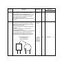
Y1 and Y2 capacitors are accepted across basic
insulation.
Y1 and Y2 capacitors are accepted across
supplementary insulation.
The enclosures of Y1 capacitors are considered to
comply with the requirements for reinforced
insulation with the exception of the area near to
the leads where the insulation becomes thinner
Only the white area is to
be considered as
reinforced insulation
Clause
1.5.7.2
Decision
Comments
Subclause 1.5.7.2 establishes the principle that
two resistors can be conn ected in series across a
double /reinforced insulation provided the are the
same value, they each comply with the creepage
and clearance requirements and the accessible
circuits comply with the Limited current circuits
requirements.
Subclause 6.1.2.1 indicates that components
across the barrier can be removed during the
electric strength test provided the circuit complies
with the 10 mA limit during the test described in
figure 6A.
The
situation
Is it possible to bridge a TNV barrier with one
resistor/two resistors?
One resistor across the TNV barrier is allowed
provided that the tests of Scl. 6.1.2.1 and 6.2 are
passed and the requirements for cre epage
distances and clearances and the requirements of
Scl. 5.1.8 are fulfilled.
The
question
The
decision
1.7.1
If the rated voltage marked on the equipment
exceeds 250 V then the components should also
be suitable for this voltage.
1.7.1
Laptop computers, which are supplied by SELV
and in which hazardous voltages are generated,
cannot be Class III and therefore must be Class I
or Class II. If they are designated Class II, the
double square symbol shall be required.
It was agreed that a lap-top or notebook computer
supplied from SELV circuits and in which circuits
at voltages which exceed 42.4 V peak or 60 V d.c.
complying as limited current circuits is considered
to comply with the definition of Class III equipment
The
decision
Dec
No
Document
Ref
Item
EE(Chm)3/02
10.4
02/12
96/2
EE(Chm)5/96
6.6
91/17
EA(FI)3/91
4.11
EE(Chm)1/94
6.12
A comment
1.7.1
Only the one set voltage of an internal voltage
regulating device should be indicated on the
outside
The
decision
94/13
EE(Chm)1/94
10.3
1.7.1
Safety related components shall be marked with a
trade mark (logo) and an identification number or
code. For a component without independent
certification that is dedicated for use in one or
more specific models the identification may be in a
form of a code
The
decision
00/8
EE(Chm)5/00
10.5
1.7.2
Safety relevant documentation has to be as a
hardcopy.
The Users Manual may also be on a diskette
The
decision
95/11
EE(Chm)5/95
9.7
Clause
1.7.2
Decision
A Class III equipment with an enclosure made of
HB material and using a non -special connector for
the a.c./d.c. input has to have a marking stating
the following:
"For use only with power supply
MANUFACTURER, MODEL"
This statement shall also be in the user instructions.
The
decision
Dec
No
99/2
Document
Ref
EE(Chm)7/99
Item
9.3
EE/Chm)1/01
6.2
EA(FI)1/91
4.5
See below
for
amended
decision
It may be considered that the Decision 99/2,
requiring marking of manufacturer and model of
the power supply on the product, is too stringent in
light of sub clause 1.7.2.
The
situation
A possible solution has been discussed with some
OSM delegates about accepting a text on the
product having the following information:
"For applicable power supplies see user manual"
or
"Use only power supplies listed in the user
manual"
The user manual must then have a listing of
manufa cturer and model of the relevant power
supplies.
A proposal
Decision 99/2 is amended to read as follows;
A Class III equipment with an enclosure made of
HB material and using a non -special connector for
the a.c./d.c. input has to have a marking stating
the following:
"Use only power supplies listed in the user
instructions"
or
"For applicable power supplies see user
instructions"
This statement shall also be in the user instructions.
The user instructions must then have a listing of
manufacturers and models of the relevant power
supplies.
In respect of reducing the risk of ignition and
spread of flame, Method 2 of 4.7.1 of EN
60950:2000 is recommended.
1.7.6
Comments
The
amended
decision
01/8
The wording "special fusing characteristics"
includes breaking capacity.
The
situation
91/11
To be able to accept one fuse marking in Europe,
in the USA and in Canada, markings "mA" and "A"
can still be accepted. Therefore the following kind
of markings are accepted:
T315 mA
LF4 A H
250 V
250 V
The
decision
Clause
1.7.8.3
Decision
It is not acceptable to mark "I" and "0" on a
functional switch of a lap-top or notebook
computer where, for example, the charging circuit
is energised at all times.
If marked, it should be "I" and stand-by:
No marking at all is acceptable.
The marking “POWER” is not acceptable.
Comments
Dec
Document
No
93/3
Ref
EA(GB)3/93
Item
6.3
Addition to
1993
Decision
99/3
EE(Chm)99
9.4
The
decision
1.7.12
Testing houses shall put a note in the test report
mentioning in which language the markings
regarding safety have been checked.
Safety markings in all official languages of
CENELEC countries need not be checked when
the CCA certificate is issued.
The
decision
91/2
5
EA(FI)3/91
4.15
1.7.15
Lithium batteries includ ed in integrated circuits are
not considered as replaceable.
There must be advice in the service manual
concerning the disposal of these parts.
The
decision
95/1
3
EE(Chm)5/95
9.8
2.1.1
A modem-card, if it is separately sold and intended
for use in operator access areas, has to be tested
for the relevant protection of TNV-circuits.
The
decision
99/4
EE(Chm)7/99
9.5
2.1.1.4
Double or reinforced insulation shall also be
required between wires in SELV circuits and metal
parts with hazardous voltages inside the
equipment.
The text "because of the wording of the standard"
was deleted from the Decision No 91/6 at the 1994
meeting.
Sub-clause 2.1.1.4 also leads to 3.1.4 which, in
turn, leads to 2.10.5.
The
decision
91/6
EA(FI)3/91
4.1.5
Note s
-
EE(Chm)1/94
6.13
2.1.2
Products which are considered completely
hazardous when covers are removed do not need
additional protection e.g. monitors. Opening of an
enclosure of a monitor is considered to be
intentional because inside the equipment there are
not parts which need servicing, but repairing.
The
decision
91/1
2
EA(FI)3/91
4.5
2.2.4
SELV circuits can be connected to non-SELV
circuit if the equipment still complies with the
requirement of Scl. 2.2 in case of single fault
condition.
The
decision
91/1
6
EA(FI)1/91
4.10
2.2.4
DC centralized battery systems Voltage in
Telecommunication Central offices:
Following the IEC TR 62102, Annex B, a 75 V d.c.
stationary battery system is considered TNV 2 and
double or reinforced insulation from the mains is
required. The installation instructions should
provide guidance on how to ensure that the
system will not become hazardous after a single
fault according to 1.7.2.
The
situation
The
decision
EE(Chm)3/03
5.1.9
Confirmed
by WG7 of
TC108
03/5
Clause
See 2.5 below
– Ref
EE(Sec)1/04
2.2.5
2.4.2
2.4.2
2.5
Decision
Until the standard is changed condition 2 to table 9
should be read as follows:
Overcurrent protective devices within the
equipment shall be bypassed in turn.
This decision is shown against an incorrect subclause number.
The sub-clause number needs correcting to 2.5
and the decision moved to the appropriate position
in the decisions list. Furthermore, the reference to
table 9 needs correcting to table 2C.
When checking the frequency, and for the
calculation of the maximum peak current, the
frequency measured when the circuit is loaded
with a 2000 O resistor is considered to be the
value to be used.
As already covered in the above decision on 2.4.2
from 1994, the maximum peak current and the
frequency measured when the circuit is loaded
with the 2000 O resis tor has to be considered. If
there is still a second frequency (envelope
waveform) the most unfavourable value has to be
taken into account.
In the case mentioned, 330 Hz is the decisive
frequency.
Comments
The
decision
Dec
No
95/19
Document
Ref
EE(Chm)5/95
Item
9.17
EE (Sec) 1/04
14.4
94/15
EE(Chm)1/94
10.7
00/9
EE(Chm)5/00
10.9
98/5
EE(Chm)5/98
9.14
Proposal
for correction
and
improvement
The
decision
WG8 of
IEC-TC74
agrees
The
decision
The chairman of WG5 of TC74 advised to use the
measuring network of Annex D Figure D.1 which
takes all frequency problems into account. He is
preparing a paper on the problems of different
frequencies in touch currents. I will circulate that
paper as soon as it is available.
A comment
by OSM-EE
chairman
of.year
2000
Higher voltages are not allowed (Tables 2B and
2C to be followed). Behind a limited power source
higher voltages can be created within secondary
circuits out of the low voltage output of the limited
power source. HB material is possible, even if
there is, for example, a 1000 V back-light source.
However, an assessment has to be made to
ensure that there is no fire or ignition hazard.
The
decision
Clause
Decision
Comments
Dec
No
2.5
2.5
Limited Power Source (Battery supplied
equipment): Battery supplied equipment with an
enclosure of HB material shall only be used with
batteries that are in compliance with LPS.
Alternative batteries on the market may not
comply with LPS limits, and shall therefore not be
used with such equipment.
With reference to the decision 99/2 to 1.7.2 for use
of alternative Power Supplies (ref. below), it is
proposed to consider a similar decision for
alternative batteries for battery supplied equipment
with an enclosure of HB material.
Battery supplied equipment with an enclosure of
HB-material has to have a marking stating the
following, as the battery is to comply with the
requirements for LPS:
"For use only with battery MANUFACTURER,
MODEL". This statement shall also be in the userinstructions.
Alternative marking:
"Use only batteries listed in the user -instructions"
or, "For batteries see user-instructions". This
statement shall also be in the user-instructions.
The user instructions must then have a listing of
manufacturer and model of the relevant batteries.
The decision now shows as;
See also
2.2.5 above
– Ref
EE(Chm)5/
95
Until the standard is changed, condition 2 to table
2C should be read as follows:
Overcurrent protective devices within the
equipment shall be bypassed in turn.
2.6
It is acceptable to use a track on a PCB as the
safety earth path, provided it meets the
requirements of the relevant tests.
The
situation
Document
Ref
EE(Chm)3/02
Item
10.7
EE (Sec) 1/04
14.4
EA(GB)3/93
6.10
The
proposal
The
decision
02/13
Decision
95/19,
corrected and
renumbered:- 04/10
The
decision
93/6
Clause
Decision
Comments
Dec
No
2.6.3.3
Subject: protective bonding conductor test current
and duration for d.c. powered equipment rated in
excess of 16 A - Sub clauses : 2.6.3.3 / 2.6.3.3 /
2.6.3.4
The referenced standards indicate that the
protective bonding conductor test current and its
duration for d.c. powered equipment ar e specified
by the manufacturer when the current rating
exceeds 16 A.
Which are the minimum current and time values
we should accept for such test?
The
situation
Document
Ref
EE(Chm)3/02
Item
10.8
Referring to
60950:1999
and
60950 -1:
2000
The
question
The current rating of the circuit means the current
rating of the protective device (see meeting of
WG8 of IEC TC74 in Helsinki). When the
manufacturer specifies a test current and duration,
that current and duration shall first be used to
check that the protective device will operate in this
condition. If the protective device does operate,
the test current and duration specified by the
manufacturer shall be used to test the protective
bonding conductor. If the protective device does
not operate, the testing laboratory shall ask the
manufacturer to specify a more suitable
combination of test current and duration.
The
decision
02/14
2.6.5.7
Internal connections for earth-continuity achieved
by one rivet in combination with a lock washer are
acceptable.
The
decision
94/16
EE(Chm)1/94
10.8
2.7.1
The maximum rated current in different CENELEC
countries for fuse-links inside Pluggable
Equipment Type A are as follows:
Denmark 16 A
Finland 16 A
Norway 16 A
Sweden 16 A
Switzerland 16 A
United Kingdom 16 A
The
decision
91/1
EA(FI)3/91
3.4
2.7.4
Two protective devices may be required in
equipment intended to be connected to an IT
power system.
In Norway IT power system is used. However, only
one protective device can be accepted there.
The
decision
91/1
3
EA(FI)1/91
4.7.1
The
decision
94/16
EE(Chm)1/94
10.8
The
decision
91/4
EA(FI)3/91
4.1.1
EE(Sec)1/04
14.6
2.7.4
2.10
One fuse is acceptable based on the judgement
that the installation fuse could protect the
appliance in every earth fault case.
Partial discharge test, VDE 0884 (for example, for
optocouplers), is not accepted for the time being.
Parenthetical note added.
Additional
information
Addition to
decision
Clause
2.10
Decision
Comments
Dec
No
94/18a
Document
Ref
EE(Chm)1/94
Item
10.10
EE(Sec)1/04
14.5
The insulation of an accessible LED which is
connected to hazardous voltage shall fulfil the
requirements of Clause 2.10, but is not tested with
the steel sphere.
- Line space added here The foil of a membrane switch is allowed to be
used as insulation against hazardous voltages if
the mechanical construction provides sufficient
strength and lifetime.
The
decision
2.10
The insulation between the heat sink and the
current carrying parts of an electronic component
(oxide layer) can only be considered as functional
insulation.
The
decision
94/19
EE(Chm)1/94
10.11
2.10
The insulation of the outside of a capacitor
according to IEC 60384 -14 2.ed. fulfils the
requirements for basic insulation. For reinforced
insulation the distance requirements of EN 60065
and EN 60950 must be fulfilled.
The
decision
95/8
EE(Chm)5/9 5
8.2
2.10
Insulation between parts directly connected to the
mains in front of a fuse has to fulfil the
requirements for operational insulation or pass the
test of 5.3.4 b).
For judging distances (combination of creepage
and clearance) from the high voltage connection of
a CRT, table 2K or according to subclause 2.1.1.1
(paragraph after Note 4), the dielectric strength
test is to be used.
Reinforced insulation is required to the outer
surface of an enclosure (when of insulating
material) and operational insulation is required to
an internal, earthed part.
The
decision
95/14
EE(Chm)5/95
9.12
The
decision
95/15
EE(Chm)5/95
9.12
According to 3.1.4, the insulation of primary and
secondary lead outs need only to fulfil the
dielectric strength test.
Force of 10 N shall be applied to all internal parts
whether they are accessible or not. (See 4.2.2)
The
decision
95/16
EE(Chm)5/95
9.13
The
decision
91/7
EA(FI)3/91
4.1.6
In a transformer, the highest occurring working
voltage is the basis for insulation requirements.
Outside the transformer the voltage actually
measured is used. If two or more secondary
windings are connected together, even outside
the transformer, the voltage actually meas ured on
each winding is the basis for insulation
requirements provided that the relevant windings
are insulated from each other inside the
transformer.
If the secondary voltage is not accessible, only
functional insulation is necessary.
The
decision
94/14
EE(Chm)1/94
10.5
10.6
2.10
2.10
2.10.1
2.10.2
94/18 b
Clause
Decision
Comments
Dec
No
2.10.2
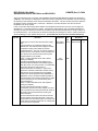
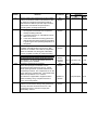
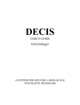
There is an LC ignite r for a high pressure lamp.
The open -circuit output voltage of the igniter is as
indicated in the figure.
One igniti on cycle takes approximately 4 s . During
the 4 s period, Upp is approximately 5 kV for a
maximum of 1 s. After 1 s , the voltage decreases
to approximately 500 Vpp , and after the 4 s the
cycle stops (no output).
If a lamp is connected and ignites , the cycle will
stop immediately. The normal lamp output voltage
is approximately 160 V square wave.
Do delegates agree with the proposal for Amd 1 of
IEC 60950-1 and therefore see the described
signal as a starting pulse and its r .m.s. value not
taken into account when determining the minimum
creepage distance?
If so, what about the pulse duration? Is , for
example, a pulse duration of 5 s acceptable, or
10 s?
At the moment it is advised to use the table of
IEC/EN 60926.
We have to take into account repeatable high
voltage if the lam p does not conduct (during start
or in fault conditions).
The ongoing work in TC74 WG6 (now TC108 74TT-WG6) will be monitored. The latest paper
will be distributed for information.
“The l atest paper” is proposals for EN 60950 -1,
2nd edition relating to Sub-clauses 2.10.1.7,
2.10.2.1, 2.10.3.5 and 2.2.3.
Latest papers are now 108_100e_CDV and
108_123e_RVC. Subject to amendments,
108_100e_CDV has now been approved as FDIS.
In the RVC there were no technical comments on
2.10.1.7, 2.10.2.1, 2.10.3.5, or 2.2.3.
See 108_100e_CDV (or the subsequent FDIS) in
respect of this question, and refer to Sub-clauses
2.10.1.7, 2.10.2.1 and 2.10.3.5.
The
situation
The
question
The
decision
Comment
Additional
comment
by OSM
Secretary,
December
2004
02/18
Document
Ref
EE(Chm)3/02
Item
12.4
Clause
Decision
Comments
Dec
Document
Ref
EE/Chm)5/98
Item
9.8
EE(Chm)5/98
9.9
93/7
EA(GB)3/93
6.11
Additional
decision
97/10
EE(Chm)5/97
9.8
The
decision
95/17
EE(Chm)5/95
9.14
Requirements for a tape for insulation:
Based on cl 1.3.4, when an adhesive is required to
maintain a level of safety (e.g. adhesive tape),
then it is recommended to apply the cl 4.6.5.
In light of the response from Mr Ferguson (IEC
TC 108/MT 2 Interpretation Panel) referred to at
the end of Annex J to the minutes of the OSM-EE
April 2004, the OSM-EE might wish to review
Decision No 03/7 again.
Insulation between semiconductors (mains) and
heat sinks. Either a second sheet is required, or it
must be checked whether the distance through
insulation has to be increased to comply with the
requirements of clauses 4 and 5.
The
decision
03/7
EE(Chm)3/03
12.4
The
decision
95/7
EE(Chm)5/95
8.1
2.10.5.2
2.10.5.2 is not to be used for winding wires. Only
2.10.5.4. applies.
The
decision
96/15
EE(Chm)5/96
10.2
2.10.5.2
The tests on non-separable 3-layer foils are done
on a separate sample using a test voltage of
4.5 kV (3 x 1 .5 kV) for reinforced insulation
Decision made in the 37th meeting of TC74 WG6
in Stuttgart.
The
decision
00/1
EE(Chm)5/00
12.3
TC74/WG6
(Sec) 25
37.9.1
96/16
EE(Chm)5/96
10.2
95/2
EE (Sec )1/04
EE(Chm)5/95
14.7
5.1.7
2.10.3.2
Table 2J stops at 1300 V repetitive voltage. For
higher voltages, extrapolation of the table is
possible.
The
decision
2.10.4
Table 2L stops at 1 kV working voltage for
Pollution Degrees 2 and 3.
For higher voltages Table 4 of HD 625.1 S1
(IEC 60664-1) has to be used.
In a 5 V circuit on the primary side of a switch
mode power supply, having a direct connection to
the mains (230 V a.c.), the working voltage to be
used for table 6 is 250 V a.c. If the working
voltage is lower than 250 V, it is seen as 250 V.
If it is higher, distances have to be calculated
according to 2.10 and where a higher working
voltage than the mains voltage (250 V) is present,
higher requirements for creepage distances,
clearances and insulation (high-pot) tests have to
be taken into account.
The plastic enclosure of a semiconductor can be
considered as basic insulation. These components
including alternatives must be listed in the list of
critical components and there must be a remark in
the service documentation.
The
situation
The
decision
The
decision
2.10.4
2.10.5
2.10.5
2.10.5.1
2.10.5.4
2.10.8
2.10.5.4 could also be used for insulation
materials that are similar to polyimide as long as
they comply with the tests of Annex U.
Decision 96/16 deleted.
The requirements for distances through insulation
are to be applied to lateral separation between
layers provided that the thermal cycling test is
passed.
No
98/3
98/4
NOTE
Comment
The
decision
The
decision
Clause
Decision
Comments
Dec
No
91/15
Document
Ref
Item
EA(FI)1/91
4.8
and
4.9
3.4.2
In pluggable equipment, the mains plug can be
considered as a disconnect device. Disconnect
devices shall be either a double-pole mains switch
(IT power system: all-pole mains switch), or a
mains plug.
Therefore, in pluggable equipment, a single-pole
mains switch, or a micro-switch, can be accepted.
In pluggable equipment, a semiconductor or a
combination of semiconductors can perform
functional switching for standby operation.
Force of 10 N shall not be used for testing the
compliance of § 4.3.4. Securing of wires is
important. The natural movement of the
components shall be taken into account.
A heat shrinkable tubing is an acceptable means
of additional security to single clamping or
soldering of internal wiring, but not for the
termination of the mains cord.
The
decision
The
decision
91/14
EA(FI)3/91
4.8
The
decision
95/4
EE(Chm)5/95
5.1.11
4.3.5
If there is a possibility of mis -mating of modular
connectors (e.g. RJ-11, RJ-12 etc.) accessible for
the user, tests have to be made to verify that the
SELV limits remain. If the voltage of the TNVcircuit is known this value is used, otherwise the
test generator of 2.3.5 (Figure 2E) is used for
testing.
The
decision
98/6
EE(Chm)5/98
9.14
4.3.6
Every NTR concerning an equipment with plugs as
part of the enclosure shall have additional
information about the tests made on the plug. The
circulated 2 pages give an example, for Class II
plugs. Class I plugs shall be handled accordingly.
The
decision
96/10
EE(Chm)5/96
8.1
4.3.8
The requirements for lithium cells apply to
separate devices such as memory cards, remote
control units etc.
The
decision
93/10
EA(GB)3/93
6.18
4.3.8
Whe n calculating the reverse current the voltage
of the battery is considered to be zero.
The
decision
95/13
EE(Chm)5/95
9.8
4.3.13
If one type of display tube has been tested for
ionising radiation, similar types can be accepted
without test. The ionisation test shall be carried
out under normal operating conditions.
The
decision
93.8
EA(GB)3/93
6.16
4.3.13
(A decision was made in 1995 and applied to both
EN 60950 and EN 60650) but see below;
95/38
EE(Chm)5/95
10.12
96/4
EE(Chm)5/96
6.22
4.3.4
4.3.4
For apparatus comprising a laser product the
class, the laser-data and the relevant warning
marking shall be stated in the test report.
Modified
decision
Clause
Decision
Comments
Dec
No
4.3.13.5
Which version of Laser standard – EN 60825 -1 –
to use, as referenced by EN 60065, 6th Ed Cl 6.2
and EN 60950-1 Cl 4.3.13.5.
Adopt the CTL Decisions DSH 538 and DSH 539.
As an alternative to the Normative references in
the standards mentioned above, IEC 60825-1/A2:
2001 can be used in combination with this
standard, when agreed to by the manufacturer.
The
question
The
Decisions
Document
Ref
EE (Sec)1/04
Item
5.1.2
EA(GB)3/93
6.32
EE(Chm)3/02
10.10
5.2
04/1
538 – 60065
and
539 – 60950
(Identical)
In connection with this agenda item, it was noted
that the date of withdrawal (dow) applicable to A2
of EN 60825 -1 has been revised and is now
1 July 2005. The CENELEC secretariat will issue
a corrigendum for the dow change.
Comment
4.4
If it is clearly evident that there are no hazardous
moving parts, then marking detailed in this clause
is not required.
The
decision
4.4.2
Protection in Operator Access area
Small spinning fans (typically 5 -8 cm size) in user
accessible area may be evaluated differently due
to 4.4.2, consideration of hazardous moving parts.
The access to the fa n may be directly from the
outside, or when opening a door or cover.
What should be the criteria for when access to
such a small spinning fan is considered involve a
hazardous moving part that requires a guard?
(Speed, sharpness of blades etc.
causing possible injury to e.g. fingers.)
20.101 of EN 60335-2-80 specifies the following:
Fan blades, other than those of fans for mounting
at high level, shall be guarded unless their leading
edges and tips are rounded and
- they have a hardness less than D 60 Shore, or
- they have a peripheral speed less than 15 m/s
when the fan is supplied at rated voltage, or
- the fan has a power output not exceeding 2 W
when supplied at rated voltage.
NOTE: An edge w ith a radius of not less than
0.5 mm is considered rounded.
Compliance is checked by inspection and by
measurement.
The
situation
The
decision
02/20
The original, not a copy, of CCITT test form No 3
shall be used at the heating test in normal use of
telefaxes.
An alternative means is the Test Form Nr.4 named
"Black -White facsimile test chart BW01 (ITU-T test
chart No,: 4)
A thin plastic coating (spraying) on the external
surface of the metal enclosure is not taken into
account when determining the temperature rise on
touchable metal parts.
The
decision
91/32
EA(FI)3/91
Addition to
decision
98/1
EE(Chm)5/98
The
decision
91/9
EA(FI)3/91
4.5
4.5
93/16
The
question
4.3.2
Clause
Decision
Comments
Dec
Document
No
93/14
Ref
EA(GB)3/93
Item
6.24
4.5
For the heating test requirements of optocouplers,
reference should be made to manufacturer's data
for maximum operating temperature as well as
manufacturer's data for input and output currents.
It should be ensured that the optocoupler is
operating within its design parameters.
The
decision
4.5
a) A declaration with adequate information from
the equipment manufacturer is accepted to
classify insulating materials.
b) Information from the UL Yellow Book may be
taken into account.
c) In the case of different insulating systems the
mate rial with the lowest operating temperature
is governing the total operating temperature of
the system.
The
decision
95/22
EE(Chm)5/95
9.21
4.5
For the acceptance of coils of RFI filters, Table 16
condition 5 should be taken into account. With
reference to Condition 5 of Table 4A, temperature
The
decision
98/7
EE(Chm)5/98
9.15
The requirements of this sub-clause are applicable
to the fire enclosure and the electrical enclosure.
This decision, for the 2nd Ed, deleted because of
the updating of the standard
The
decision
Decision
deleted
93/9
EA(GB)3/93
6.17
04/14
EE (Sec) 1/04
14.8
Following construction is accepted:
There are openings in the bottom of a fire
enclosure that are larger than 40 mm². Above
these openings there is a printed board which is
horizontally mounted. The components are on the
upper side of the printed board. The printed board
fulfils the requirement of V-1 material.
This decision is applicable to equipment with a
mass exceeding 18 kg. Compliance clause in
4.6.2 covers this problem.
The
decision
91/21
EA(FI)1/91
4.12.3
EE(Chm)5/96
6.25
EA(GB)3/93
6.21
limits on individual coils, being part of RFI filters,
can be accepted according to component rating.
4.6.1
4.6.2
4.6.2
It is acceptable to have a printed circuit board
(above a fire enclosure having holes greater than
40 mm²) with holes of less than 40 mm², if the
components close to the holes comply with
flammability class V-1.
Addition to
decision
The
decision
93/11
Clause
Decision
Comments
Dec
No
4.6.5
4.7
Document
Ref
EE(Chm)3/02
Item
12.1
Compliance is checked by examination of the
construction and of the available data. If such
data are not available, compliance is checked by
the following tests.
1. What documentation is required?
For example, description of the materials from
which the adhesive is composed + test results
of a cyclic test over 600 h at -30 °C to +70 °C.
Is this sufficient for parts not subject to heat?
2. Is a UL 746C (Polymeric Materials - use in
electrical evaluation) approved adhesive
acceptable?
3. Is proof of resistance to heat at 90 °C
(UL RTI 90, QMFZ2) sufficient?
Other
We do not have sufficient experience to be sure
that any of the suggested conditions or tests in
item 1,2 or 3 above are equal to or better than the
requirements in 4.6.5 or 4.3.22.
Available data have to prove compliance with the
requirements of 4.3.22 or 4.6.5. If not, the
relevant tests have to be applied.
The
situation
with
questions
The
decision
02/17
Declaration of used materials with adequa te
information from the equipment manufacturer is
acceptable.
Furthermore, the flame resistance of plastic
materials listed in the UL Yellow Book can be
taken into account when checking the compliance
with § 4.7.3
The flame resistance of plastics materials listed by
national certification bodies such as in the Yellow
Book by UL can be taken into account when
checking the compliance with Sub-clause 4.7.3.
The
decision
91/19
EA(FI)1/91
4.12.1
Addition to
decision
93/18
EA(GB)3/93
6.39
Addition
93/18
amended
04/15
EE (Sec) 1/04
14.9
In the flammability assessment of PCBs, a
declaration that the manufacturer uses V-0 or V-1
rated PCBs as required is acceptable.
The test report should detail material
manufacturer, type reference and flammability
rating as a minimum for other materials.
Addition to
decision
94/3
EE(Chm)1/94
6.16
In cases where the equipment manufacturer is
unable to obtain the appropriate information, due
to the unwillingness of the component
manufacturer to divulge proprietary data,
acceptance may be based on either
1. a Certificate of Conformity (C of C), or
2. a written declaration
from the component manufacturer.
The C of C, or declaration, shall confirm the
flammability rating of the plastic materials.
However, this exception is not allowed for
enclosure materials. These must also meet the
requirements of clause 4.2 (Mechanical strength
and stress relief)
Addition to
decision
95/3
EE(Chm)5/95
5.1.9
Comment
Clause
4.7
4.7
4.7
4.7
4.7
4.7.2.1
4.7.3
Decision
Comments
Dec
Document
No
96/5
Ref
EE(Chm)5/96
Item
6.23
Components may be considered to have individual
fire enclosures.
Thin tape can be used to provide a fire enclosure
for transformer windings etc, provided the tape
meets V-1 minimum or the complete transformer
including the tape meets Appendix A2 test.
A2 will be deleted with Amendment 1
The
decision
Small openings in small electromagnets, motors
etc should meet the requirements of 4.6 .
Small parts of HB materials in a fire enclosure can
be accepted based on the judgement that they
have adequate spacings from ignition sources.
If the product enclosure is made of HB material
there have to be internal fire enclosures for parts
where the limited power source output criteria are
not met.
The
decision
The
decision
93/17
EA(GB)3/93
6.35
95/20
EE(Chm)5/95
9.19
The
decision
95/21
EE(Chm)5/95
9.20
If the battery is within a fire enclosure we could
accept a material HB or better, based on the
experience in 4.4.3.3 of EN 50091-1-1.
The
decision
99/5
EE(Chm)7/99
9.13a
Parts requiring a fire enclosure:
Some apparatus powered only by batteries are not
required to have a fire enclosure because, beyond
the batteries , the power is limited by PTCs or other
devices according to 2.5. However, the batteries
are not power limited: therefore fire enclosure is
needed.
Do you agree to consider the metal can of the
battery acting as fire enclosure?
The
situation
EE(Chm)3/02
10.13
The metal case of the battery can be considered
as fire enclosure, but the battery has also to
comply with 4.3.8.
The
decision
02/15
Materials of coil formers and partition walls shall
fulfil the requirement of V-2 material.
(The word, “partition” added as shown above.)
The
decision
Amendmen
t to
decision
The
decision
91/22
EA(FI)1/91
4.12.3
EE(Chm)1/9 4
6.14
91/23
EA(FI)1/91
4.12.3
NOTE
The
question
4.7.3.2
Liquid crystal display (LCD) is tested as a
"sandwich" and it shall fulfil the requirement of a
fire enclosure.
4.7.3.2
Enclosures of a keyboard or similar devices (e.g.
mouse, trackball) can be accepted to be made of
material class HB based on abnormal test.
The
decision
95/24
EE(Chm)5/95
9.27
4.7.3.2
The 13 mm requirement of clause 4.7.3.2 is not
relevant to the requirements of clause 4.6.
The
decision
93/12
EA(GB)3/93
6.22
Clause
4.7.3.2
4.7.3.2
Decision
Thin metal foil may be used in the construction of
a fire enclosure (on HB material) provided:
1. The complete enclosure shall be tested to
Appendix A1 or A2, and
2. The foil covers all areas where there is a
source of ignition.
There is no mechanical strength requirement on
the foil other than that for the enclosure.
The use of metalised coating sprayed on the
inside of an enclosure made of HB-material is also
acceptable provided the tests according to
Appendix A1 or A2 are met.
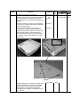
Materials of Fire Enclosure:
A supplier of LCD projectors (typical weight from
1 to 5 kg, and intended for ceiling mounting and/or
transportable use together with notebook
computers) offers a ceiling mount accessory kit.
The kit has two major parts: one piece mounts to
the ceiling with permanent fasteners, the other
piece attaches to the projector with screws. Both
halves go together by aligning each half to a
specified feature and twisting them into position.
The halves are locked into place by turning
knurled screws with finger pressure. Mounting
and un-mounting the units do not require the use
of tools.
Do the delegates agree that if the projector can be
fixed to the ceiling by any manner, even without
requiring the use of tools, the product must be
considered as fixed and therefore the fire
enclosure must be rated 94-5V?
For projectors specified b y the manufacturer for
ceiling mounting, with or without a tool, the fire
enclosure must be rated 5V or better.
However, see Decision 04/6 below
Comments
The
decision
Addition to
decision
Dec
Ref
EA(GB)3/93
Item
6.23
94/2
EE(Chm)1/94
6.15
EE(Chm)3/02
10.13
The
situation
The
question
The
decision
Comment
Document
No
93/13
02/16
Clause
4.7.3.2
Decision
Comments
EN 60950 3 rd edition and EN 60950 -1
Decision 02/16 states, “For projectors specified by
the manufacturer for ceiling mounting with or
without a tool the fire enclosure must be rated 5V
or better.”
Applicability
The
situation
Is this applicable to any other type of equipment
mounted on a vertical surface and/or suspended
under any other surface?
How would the delegates determine the fire
enclosure (V-1 or 5V) for the following small
equipment intended for desktop use and/or to be
mounted/suspended on a vertical surface by
notches provided in the bottom of the enclosure:
for example, routers, base stations for cordless
telephones?
Question 1
Dec
Document
No
Ref
Item
EE (Sec)1/04
13.3
Question 2
Notches
Movable equipment is considered to include wallmounted equipment whose mounting method
permits removal without a tool by an operator.
Consequently, the equipment referred to is
considered to be movable: this allows the use of
V-1 material.
The decision
04/6
Clause
Decision
Comments
Dec
No
5.1
EN 60950 3rd edition
A professional image server for control room
application uses a redundant power supply with
two mains inputs, each input connected to a
different power mains. The redundant supply is
provided to keep the server operational in very
critical applications, when one mains supply would
fail.
The unit is provided with two detachable power
supply cords with IEC 60320 appliance couplers,
is rack mounted and considered pluggable Type A
equipment.
Problem: this unit cannot comply with the touch
current requirements in IEC 60950 3rd edition or
60950-1 because the touch current exceeds the
strict limit of 3.5 mA for pluggable Class A
equipment (Table 5A) at 264 V/60 Hz.
However, in the m ost recent CDV of IEC 60950-1
(2nd Ed), there are a lot of changes in the
requirements for touch current for equipment using
redundant power supplies and for equipment
located in restricted-access locations. When
applying these new requirements, the unit would
pass the touch current requirements even when
the touch current is higher than 3.5 mA.
Is it acceptable to apply already these new
conditions beforehand, so that this type of
professional eq uipment can be judged compliant
with the intention of the safety standard? Could
we use a kind of text to introduce in the remarks
area of the test report?
It was agreed that equipment with touch current
exceeding 3,5 mA may be permitted, but only if
the equipment complies with the requirements of
5.1.7 of the draft Edition 2 of IEC 60950 -1 as
shown in the IEC Document 108/100/CDV.
This decision is as written in theamendment to
the minutes of the meeting.
Applicability
The situation
Document
Ref
EE (Sec)1/04
Amendment
to above
document
9 August
2004
Item
13.4
The question
The decision
04/7
Comment
5.3
Fault condition tests shall be carried out with 16 A
installation fuses.
The decision
91/1 8
EA(FI)1/91
4.11.1
5.3
Fault condition tests shall be considered and they
have to be done, even in the secondary circuit, if
there is a risk of damage to supplementary or
reinforced insulation.
The decision
91/2
EA(FI)3/91
3.5
5.3
According to EN 60127, a fuse will not break
within 30 minutes at less than 2.1 times the rated
current. Therefore, if the current through the fuse
does not exceed this value after the failure is
introduced, the fuse will not blow and the test is
run until steady state conditions are obtained.
The decision
95/5
EE(Chm)5/95 5.1.17
Clause
5.3
5.3
5.3
5.3.8
Decision
Comments
Dec
PTC resistors which are certified accordin g to
IEC 60738-1 , or to at least the Clauses 15, 17, J15
and J17 of IEC 60730, need not be short-circuited
under fault conditions.
The decision
No
97/7
Insert “, or to at least the Clauses 15, 17, J15 and
J17 of IEC 60730,” in the decision
Amendment
to decision
-
EE (Sec)1/04
6.1.4
Components can be short-circuited whether they
are separately approved or not. However, if a
component complies with requirements for
reinforced insulation, it shall not be short-circuited.
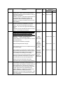
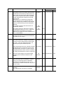
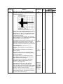
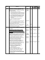
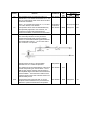
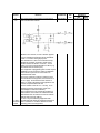
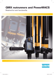
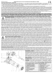
Refer to simplified diagram below:
The secondary electronic circuitry is used to
superimpose a data signal on the line voltage.
TX701 is a reinforced insulated signal transformer.
Its transformation ratio is 1:1. F1 is a fuse and L1
is a coil and C1 is a capacitor.
The decision
91/19
EA(FI)1/91
4.11.1
EE (Sec)1/04
10.9
Should a short circuit of C1 be evaluated/
assumed if C1 is a certified X-capacitor?
The question
Yes, taking into account the definition of the use of
a Class X capacitor given in Sub-clause 1.5.3 of
EN 132 400, the X2 capacitor used as shown in
the simplified diagram should be short-circuited as
a fault condition. This is because a failure of the
capacitor might cause a risk of electric shock from
the secondary circuit.
The decision
04/4
Temperature rises higher than 300 °C can be
accepted if the manufacturer has proved that the
material in question withstands the temperature.
The decision
91/3
EA(FI)3/91
3.5
The situation
Document
Ref
Item
EE(Chm)5/97 9.19
Clause
Decision
Comments
Dec
No
6.1
6.2
6.1 & 6.2
continued
below
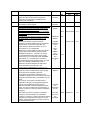
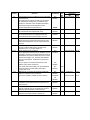
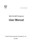
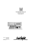
The figure shows a circuit that is connected to a
telecommunication network.
Based on the network, a TNV 1 situation applies.
T1 is a separation transformer which withstands
1500 V a.c. electric strength (ES) test.
This transformer is, due to a functional concept ,
bridged by a resistor of 38 kO to earth and by
another resistor of 38 kO to a 48 V d.c. circuit
which only has functional insulation to SELV (e.g.
an RS-232 communication port).
The equipment is pluggable type-A but will only be
installed by a service person and the installation
instructions require it to be connected to an
earthed socket outlet.
So, for the protection of telecom network users
from hazards in the equipment, the exclusions of
6.1.2.2 apply. This means that the resistor of
38 kO to earth is allowed for this application and
can be accepted without ES test.
For the resistor to the 48 V d .c. circuitry, cl 6.2
applies (protection of equipment users from
overvoltages on telecom networks).
In this case there is only functional insulation to
SELV and the circuit does not withstand the ES
test between the connection for telecom network
and RS-232 connector (SELV) .
Cl. 6.2.1 says the following equipment shall
provide adequate electrical separation between a
TNV-1 CIRCUIT or a TNV-3 CIRCUIT and the
following parts of the equipment;
The situation
Document
Ref
Item
EE(Chm)3/03 5.1.8
Clause
Decision
Comments
Dec
No
6.1
6.2
continued
a) Unearthed conductive parts and
non-conductive parts of the equipment
expected to be held or touched during normal
use (for example, a telephone handset or a
keyboard).
b) Parts and circuitry that can be touched by the
test finger, figure 2A (see 2.1.1.1), except
contacts of connectors that cannot be touched
by the test probe, figure 2C (see 2.1.1.1).
c) An SELV CIRCUIT , a TNV-2 CIRCUIT or a
LIMITED CURRENT CIRCUIT provided for
connection of other equipment. The
requirement for separation applies whether or
not this circuit is accessible.
These requirements do not apply where circuit
analysis and equipment investigation indicate
that safety is assured by other means, for
example, between two circuits each of which has
a permanent connection to protective earth.
Is it necessary for compliance to perform the test
according to 6.2.2.1 (impulse test) or 6.2.2.2
(steady state ES test), or can we accept this
situation without testing if the following applies:
Separate approved surge suppressors are
provided which limit an incoming transient voltage
to a level of max 70 V before the resistor. Circuit
analysis shows that this will never result in a
hazardous voltage on the RS 232 port (SELV).
If it is obvious that the product will fulfil the
requirements, no test is necessary.
Otherwise the tests have to be performed due to
the requirements of 6.2.2.3.
The situation
continued
Document
Ref
Item
EE(Chm)3/03 5.1.8
The question
The decision
03/4
Confirmed by
TC108-WG7.
End
osm -ee (Sec) 2 / 2004
(EN 60950 Decisions 1991 – 2004)
THE DECISIONS MADE AT THE YEAR 2005 OSM-EE MEETING
EN60950 AND EN60950-1
Dec
No.
05/2
Comments: -
Standard(s):
EN 60950: 2000 and EN
60950-1:2001
Document
Ref
EE(Chm) 1/2005
Sub clause(s):
1.5 (4.5 and 5.3)
Item
10.4
From:
NEMKO
Key words:
To:
OSM/EE
Question: Shall temperature-sensing devices (NTC devices) used as fan speed
controllers be listed as critical components when they are operating under
normal conditions?
Subject:
Temperature controllers
and fan speed controllers
Decision: Short circuit or opening the NTC and other relevant fault tests in the
temperature-sensing circuit should be applicable tests. Then it is a 5.3. issue (+
blocking the fan). The situation has to be evaluated from case to case. If the
NTC protect against excessive temperatures it has to be evaluated as a safety
critical component and must then be listed.
Explanatory Notes: A thermal controller for power supply fan would not be
evaluated like a thermostat in a heating element (1.5.3). This circuit should be
evaluated like other circuits for function and safety purpose, such as heat sink
sensors and fixing sensors in printers, which will be evaluated in normal
operation and also with blocked fan and other relevant fault tests in the
temperature-sensing circuit.
Dec
No.
05/3
Document
Comments: Mr. Andersen of
Ref
NEMKO will bring the matter of
software controls to the attention of EE(Chm) 1/2005
IEC TC 108/HBSDT
Standard(s):
EN 60950:2000 and EN
60950-1:2001
Sub clause(s):
5.3
Item
10.7
From:
NEMKO
Key words:
To:
Subject:
Safety depending on software OSM/EE
control for compliance with
EN 60950
Question: An integrated circuit is used as protection against overcharging of a
lithium battery. The circuit has a register which can turn on a charge circuit,
causing problems with accepting this part, because failures in software is not
specified in 60950, and when doing testing in single fault condition, and at the
same time having (in this particular case) the software controlled charge circuit
turned on, compliance with IEC 60950 (in this case for a lithium battery) in
single fault condition causes failure with clause 5.3.
How do delegates treat software control for compliance with EN 60950?
Decision: As software evaluation is not part of EN 60950-1, OSM-EE is of the
opinion that software control can not be considered as part of a safety
protection system.
Explanatory Notes: -