1
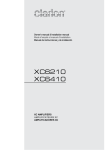
Istruzioni per l’uso
Instructions for use
REGOLATORE DI VELOCITA’
SPEED REGULATOR
RPWM
Rev. 04 – 2008
Italiano
REGOLATORE DI VELOCITA’ RPWM
Il regolatore di velocità è ideale per variare la velocità di movimento di salpa ancora o verricelli
di tonneggio o per limitare l’elevata corrente di spunto dei motori Bow Thruster e permettere così
di avere una variazione dolce e progressiva e maggiore manovrabilità in fase di attracco e
movimentazione in porto.
ELENCO COMPONENTI
n. 1 Pulsantiera PWM. Cavo estensibile a 3,5 mt.
n. 1 presa 6 poli IP 68 fissata all’apparecchio.
n. 1 cappuccio per copertura presa a spina estratta.
n. 3 Cappucci plastica per dadi M8, e 1 per dado M6.
n. 1 regolatore PWM in contenitore di alluminio anodizzato.
n. 1 istruzioni per il montaggio.
DIMENSIONI
Dimensioni centralina:
Dimensioni pulsantiera:
230 x 185 x 90 mm.
140 x 60 x 20 mm.
CARATTERISTICHE TECNICHE
Alimentazione
10 a 28V con commutazione automatica.
Frequenza di lavoro
490 Hz
Corrente massima erogabile:
CONTINUA 235 A a 12V o 24V
Corrente di punta:
max 320 A a 12V o 24V
Regolazione velocità:
continua da 6% a 100%
Per motori a 2, 3 e 4 fili.
Ventilazione forzata del dissipatore PWM
Invertitore di marcia integrato
Protezione contro l’inversione di polarità applicata.
Chiusura e apertura dei contatti relè di potenza a corrente zero.
Rampa di accelerazione regolabile da 0,8 a 3 secondi .
Controllo incollaggio relè di potenza e unità statica con segnalazione Led.
Segnalazione Led di intervento MAX temperatura con limitazione della velocità al 50%.
Segnalazione istantanea a Led di intervento MAX corrente, con arresto motore per
sovraccarico. Ripristino automatico dopo 5 sec.
Controllo efficienza unità di potenza con segnalazione guasto.
RPWM
-2-
REV. 4-2008
Italiano
Protezione software di sovracorrente con soglia impostabile tramite un quadruplo dipswitch, SW1 in funzione della seguente tabella 1 (valori nominali)
IMPOSTAZIONE MASSIMA CORRENTE MOTORE
NOTA:
Il valore della soglia di corrente per la protezione software può subire variazioni tipiche del 10%
rispetto al valore nominale.
La protezione software interviene dopo un tempo che dipende dalla percentuale di sovraccarico
secondo la seguente tabella 2:
RPWM
-3-
REV. 4-2008
Italiano
TABELLA2
CORRENTE NEL MOTORE TEMPO DI INTERVENTO
100%> I <120%
3.2 SEC
120%> I <140%
1.6 SEC
140%> I < I MAX
1 SEC
> IMAX = 320A
60 ms
Nel caso di intervento software per sovraccarico quando la corrente torna a valori normali il
ripristino è automatico dopo 5 secondi
• Protezione hardware di sovracorrente si imposta automaticamente a 320 Amp
• La protezione interviene istantaneamente al superamento della soglia.
Nel caso di intervento hardware per sovraccarico quando la corrente torna a valori normali il
ripristino è automatico dopo 5 secondi al rilascio dei comandi.
INSTALLAZIONE
STACCARE SEMPRE LA BATTERIA PRIMA DI PROCEDERE ALL’INSTALLAZIONE!
1) Montare il box su una parete verticale con il ventilatore nella parte inferiore.
2) Collegare un cavo di adeguata sezione, in funzione della potenza motore, dal POSITIVO
Batteria al morsetto + del control box interponendo una protezione elettrica (fusibile) o
un interruttore automatico ed un cavo dal NEGATIVO Batteria al morsetto M6 NEG. sulla
scheda del regolatore.
3) MOTORE A 2 FILI: Collegare i due fili del motore ai morsetti M1 e M2 del control box
4) MOTORE A 3 FILI: Collegare i due fili rot. dx e rot. sx a M1 e M2 del control box e il terzo
filo al morsetto C2 sul dissipatore
5) MOTORE A 4 FILI: Collegare i due fili rot. dx e rot. sx al contatto M3 del control box e al
contatto C2 sul dissipatore e collegare i due fili dell’avvolgimento di campo sui contatti M1
e M2 del controlbox
6) Coprire i morsetti di potenza con i cappucci di plastica neri di corredo
7) Inserire il connettore della pulsantiera nella presa e avvitare la ghiera di serraggio.
REGOLAZIONE DELLA VELOCITA’ DEL MOTORE
• Regolazione continua da 6% a 100% con potenziometro esterno.
• Rampa di accelerazione regolabile da 0,8 a 3sec. massimo. La durata della rampa è
impostabile attraverso il trimmer RV2 sulla scheda.
• Ruotando RV2 in senso orario DIMNUISCE la rampa di accelerazione.
RPWM
-4-
REV. 4-2008
Italiano
• Limitazione della velocità del motore al 50% nel caso di superamento della soglia di
temperatura di 70°C sul dissipatore interno. Quando la temperatura torna sotto i 60°C la
velocità viene riportata al 100%.
COMANDI PULSANTIERA
Tasto ON accensione con led di ON
Tasti AUM e DIM per l’impostazione della velocità
Tasti LEFT e RIGHT per il senso di rotazione del motore
Bar led velocità impostata dal 20% a 100% con 8 led
Auto OFF dopo 2 minuti dall’ultimo comando dato
Descrizione funzionamento:
All’accensione,premendo il tasto ON si accende il led ON ed il primo led a sinistra della velocità
minima.
Premendo AUM si incrementa il valore di set della velocità, i led velocità si accendono
gradualmente da sinistra a destra.
Premendo DIM si diminuisce il valore di set della velocità, i led velocità si spengono
gradualmente da destra a sinistra.
In questa fase di set velocità vengono ignorati eventuali comandi LEFT o RIGHT.
Premendo LEFT si attiva il comando rotazione motore sinistra.
Il motore si porta gradualmente alla velocità impostata in funzione del valore della rampa di
accelerazione impostato sul regolatore.
Mantenendo LEFT premuto e premendo i tasti AUM o DIM è possibile variare la
velocità. I led si accendono o spengono di conseguenza.
Al rilascio di LEFT il motore si arresta istantaneamente, i led velocità restano accesi al valore
precedentemente impostato.
Premendo il tasto RIGHT si inverte la rotazione motore, le altre funzioni come sopra.
Dopo 2 minuti dall’ultimo comando dato la pulsantiera si spegne, 10 sec. prima di spegnersi il
led ON diventa intermittente, poi si spegne assieme ai led velocità.
Al successivo comando ON, i led della velocità si accendono al valore precedentemente
impostato.
Se viene estratta la spina non viene mantenuto il set della velocità.
Al reinserimento la condizione è la stessa che si ha all’accensione.
RPWM
-5-
REV. 4-2008
Italiano
SEGNALAZIONI A LED DISPONIBILI:
LED LINE ON
LED OVERLOAD
LED INC RELE’
LED MAX TEMP
LED CCMOS
LED PWM
SULLA SCHEDA SONO PRESENTI 6 LED INDICATI NELLA FIGURA SEGUENTE:
DESCRIZIONE SEGNALAZIONI:
• LED PWM: DI COLORE GIALLO SI ACCENDE COME SOPRA E INDICA IL
CONTROLLO DEL PWM DEL MOTORE ATTIVO
• LED CCMOS: DI COLORE ROSSO SI ACCENDE PER UN GUASTO DELL’UNITÀ DI
POTENZA MOSFET.
• LED MAX TEMP: COLORE ROSSO SI ACCENDE PER TEMPERATURE DEI MOSFET
SUPERIORI A 70°C ED IN QUESTO CASO LA VELOCITÀ DEL MOTORE VIENE
LIMITATA AL 50% SI SPEGNE QUANDO LA TEMPERATURA SCENDE AL DI SOTTO
DEI 60°C.
• LED INC RELE’: DI COLORE ROSSO INDICA LA PRESENZA DI ANOMALIE NEL
FUNZIONAMENTO DELL’INVERTITORE DI MARCIA.
• LED OVERLOAD: DI COLORE ROSSO INDICA IL SUPERAMENTO DELLA SOGLIA DI
MASSIMA CORRENTE IMPOSTATA DAI DIP-SWITCH. L’INTERVENTO È GESTITO
COME DA TABELLA 2
• LED LINE ON: DI COLORE VERDE INDICA LA CORRETTA ALIMENTAZIONE
ALL’APPARECCHIO.
SEGNALAZIONI AGGIUNTIVE A SEGUITO DI:
INTERVENTO MAX CORRENTE ISTANTANEA, si accende intermittente per 6 sec. il led
OVERLOAD.
Se un pulsante di comando viene tenuto premuto il led continua a lampeggiare, il ripristino è
automatico al rilascio del pulsante.
PULSANTI PREMUTI AL POWER ON, si accende intermittente led giallo PWM.
RPWM
-6-
REV. 4-2008
Italiano
Il regolatore è in blocco, per ripristinare il funzionamento occorre rilasciare il pulsante.
TIME OUT FUNZIONAMENTO, se il motore funziona continuamente per piu di 10 minuti il
regolatore si blocca, lampeggiano i 4 led rossi.
Per il ripristino occorre spegnere e riaccendere l’apparecchio.
RPWM
-7-
REV. 4-2008
English
SPEED REGULATORS
Speed regulators are ideal for adjusting anchor winch or warping winch speed or for limiting the
elevated pick-up current of bow thruster motors so as to achieve smooth, gradual variations and
better manoeuvrability during docking and other movements inside the harbour.
LIST OF COMPONENTS
1 PWM control panel. Cord extendible to 3.5 m.
1 6-pole socket IP 68 fixed to the device.
1 cap for covering the socket when plug is removed.
3 plastic caps for M8 nuts and 1 for M6 nut.
1 PWM regulator in an anodised aluminium enclosure.
1 set of installation instructions.
DIMENSIONS
Controller dimensions:
230 x 185 x 90 mm.
Control panel dimensions: 140 x 60 x 20 mm.
TECHNICAL DATA
Power supply
10 to 28V with automatic changeover.
Operating frequency
490 Hz
Max output current:
CONTINUOUS 235 A at 12 or 24V
Inrush current:
max 320 A at 12 or 24V
Speed adjustment:
continuous from 6% to 100%
For 2, 3 and 4 wire motors.
Forced ventilation of the PWM heatsinker
Integrated rotation inverter unit
Reverse polarity protection.
Opening and closing of power relay contacts at zero current.
Acceleration ramp adjustable from 0.8 to 3 seconds.
Monitoring of power relay locking and static unit with LED warning.
LED overtemperature warning with limitation of speed to 50%.
Instantaneous LED overcurrent warning with motor shutdown after 3 sec. of overload.
Automatic re-enabling of operation after 5 sec.
Monitoring of power unit efficiency with fault warnings.
Software overcurrent protection with threshold settable by means of a quadruple DIP
switch, SW1 as indicated in table 1 below (rated values)
RPWM
-8-
REV. 4-2008
English
SETTING OF MAXIMUM MOTOR CURRENT
NOTE:
The software protection current threshold value is subject to typical variations of +/-10% in
relation to the rated value.
The software protection will trip after a given amount of time depending on the overload
percentage, as indicated in table 2 below.
TABLE 2
CURRENT IN THE MOTOR
100%> I <120%
120%> I <140%
RPWM
TRIP TIME
3.2 SEC
1.6 SEC
-9-
REV. 4-2008
English
140%> I < I MAX
> I MAX 320A
1 SEC
60 ms
If an overload causes the software protection to trip, when the current returns to normal values
operation will be automatically re-enabled after 5 seconds
• The hardware overcurrent protection is automatically set at 320 Amp
• The protection will trip instantly when the current exceeds the threshold.
If an overload causes the hardware protection to trip, when the current returns to normal values
operation will be automatically re-enabled after 5 seconds, once the controls are released.
INSTALLATION
ALWAYS DISCONNECT THE BATTERY PRIOR TO INSTALLATION!
1) Mount the box on a vertical wall with the fan side down.
2) Connect an adequately sized wire, depending on the motor power, from the POSITIVE
pole of the battery to the + terminal of the control box, interposing an electrical protection
(fuse) or automatic breaker, and another from the NEGATIVE pole of the battery to the
M6 NEG. terminal on the regulator circuit board.
3) 2-WIRES MOTOR: connect the wires of the motor to M1 and M2 contacts of the control
box
4) 3-WIRES MOTOR: connect the wires “rot. Dx” and “rot. Sx” to M1 and M2 contacts of the
control box and the third wire to C2 contact on the heatsinker
5) 4-WIRES MOTOR: connect the wires “rot. Dx” and “rot. Sx” to M3 contact of the control
box and to C2 contact on the heatsinker. Connect the wires from the field winding to M1
and M2 contacts of the control box
6) Cover the power terminals with the black plastic caps provided
7) Insert the control panel connector in the socket and tighten the locknut.
REGULATION OF MOTOR SPEED
• Continuous adjustment from 6% to 100% with external potentiometer.
• Acceleration ramp adjustable from 0.8 to a maximum of 3 sec. The duration of the ramp
can be set by means of trimmer RV2 on the circuit board.
• Turning RV2 clockwise will DECREASE the acceleration ramp.
• Motor speed limited to 50% if the temperature threshold of 70°C is exceeded on the
internal heat sink. When the temperature again falls below 60°C the speed will be brought
back to 100%.
RPWM
- 10 -
REV. 4-2008
English
PWM PUSH BUTTON PANEL
•
•
•
•
•
ON button provided with ON led
AUM and DIM buttons in order to set speed.
LEFT and RIGHT keys for motor rotation direction
speed bar let set from 20% to 100% provided with 8 leds
Auto OFF after 2 minutes since the last command is given
Functioning:
In order to power on press the ON button, the ON led and the first led on the left side of the
minimum speed turn on.
Pressing AUM you increase the speed set value, the speed leds gradually turn on from left to
right.
Pressing DIM you decrease the speed set value, the speed leds turn off from right to left by
degrees.
During this speed regulation phase the LEFT and RIGHT controls are ignored, if they are
employed.
Pressing LEFT you activate the left motor rotation control.
The motor sets by degrees to the speed which has been set, accordingly to the acceleration
ramp which has been set on the regulator.
Keeping the left button pressed and pressing meantime AUM or DIM it is possible to change the
speed. The leds turn on and off consequently.
Releasing the LEFT button the motor stops instantaneously; the speed leds remain turned on,
according to the value which has been set before.
Pressing the RIGHT button you reverse the motor rotation, the other functions remain just the
same as above described.
After 2 minutes since the last command has been given the control reaches a OFF status, 10
seconds before turning off, the ON led blinks intermittently, then it turns off meantime with the
speed leds.
Once activating ON again, the speed leds turn on to the value that has been set before.
If you pull out the plug the speed set is not memorized. When you plug in, you will meet the
same conditions as on POWER ON.
RPWM
- 11 -
REV. 4-2008
English
AVAILABLE LED INDICATIONS AND WARNINGS:
LINE ON LED
OVERLOAD LED
RELAY LOCK LED
MAX TEMP LED
CCMOS LED
PWM LED
ON THE CIRCUIT BOARD THERE ARE 6 LEDS, ILLUSTRATED IN THE FIGURE BELOW.
DESCRIPTION OF INDICATIONS AND WARNINGS:
• PWM LED: YELLOW. IT LIGHTS UP AS ILLUSTRATED ABOVE AND INDICATES THAT
THE PWM MOTOR CONTROLLER IS ON
• CCMOS LED: RED. IT LIGHTS UP TO WARN OF A MOSFET POWER UNIT FAULT.
• MAX TEMP LED: RED. IT LIGHTS UP WHEN THE MOFSET TEMPERATURE RISES
ABOVE 70°C AND IN THIS CASE THE MOTOR SPEED IS LIMITED TO 50%. IT GOES
OFF WHEN THE TEMPERATURE FALLS BELOW 60°C.
• RELAY LOCK LED: RED. IT WARNS OF FAULTS IN STARTING INVERTER
OPERATION.
• OVERLOAD LED: RED. IT WARNS OF CURRENT VALUES EXCEEDING THE
THRESHOLD SET BY THE DIP SWITCHES. TRIPPING OCCURS AS INDICATED IN
TABLE 2
• LINE ON LED: GREEN. IT INDICATES THAT THE UNIT IS CORRECTLY POWERED.
ADDITIONAL WARNINGS GIVEN FOLLOWING:
TRIPPING OF INSTANTANEOUS OVERCURRENT PROTECTION, the OVERLOAD LED lights
up and blinks intermittently for 6 sec..
If a control button is kept pressed down the LED will continue to blink; operation will
automatically be re-enabled upon release of the button.
BUTTONS PRESSED DOWN WHEN POWER SWITCHED ON, the yellow PWM blinks
intermittently.
The regulator is disabled, to resume operation release the button.
OPERATING TIMEOUT, if the motor runs non-stop for more than 10 minutes the regulator will
be disabled. The 4 red LEDs will start flashing.
To re-enable the regulator, switch it off and back on again.
RPWM
- 12 -
REV. 4-2008
Note / Notes
MZ ELECTRONIC S.R.L.
www.mzelectronic.com
e-mail:[email protected]