1
Prodaja in zastopa:
Materm d.o.o. Morje, morska cesta 6, 2313 Fram
tel: 02 608 90 10, www.materm.si
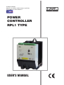
POWER
CONTROLLER
RPL1 TYPE
USER’S MANUAL
2
CONTENTS
1. APPLICATION...............................................................................................5
2. BASIC REQUIREMEMNTS, OPERATIONAL SAFETY ...............................5
3. POWER CONTROLLER SET .......................................................................6
4. INSTALLATION .............................................................................................6
4.1. Overall and assembly dimensions .........................................................6
4.2. Electrical connections ............................................................................8
4.3. Choice of the control type ......................................................................8
4.4. Connection of control signals .................................................................9
4.5. Connection of supply and load .............................................................11
5. DESCRIPTION OF CONTROL TYPES ......................................................14
5.1. Control of ON-OFF type .......................................................................14
5.2. Pulse control ........................................................................................15
5.3. Phase control .......................................................................................16
5.4. Control of the input line amplification ...................................................17
5.5. Limitation of the load current ................................................................17
5.6. Overload protection ..............................................................................17
5.7. Soft-Start function ................................................................................17
5.8. Signalling of maximal radiator temperature exceeding ........................17
6. CONTROLLER OPERATION .....................................................................18
7. TECHNICAL DATA .....................................................................................19
7.1. Electrical parameters of the high-current circuit ...................................19
7.2. Electrical parameters of the supply and control circuit .........................20
7.3. Other parameters .................................................................................20
7.4. Safety requirements .............................................................................20
7.5. Electromagnetic compatibility ..............................................................21
8. ORDERING CODES ...................................................................................22
9. MAINTENANCE AND WARRANTY ...........................................................23
3
4
1. APPLICATION
The RPL1 power controller is destined to control the load power in function of the
input control signal for following types of loads:
l resistive, wit a positive temperature coefficient of resistance;
heaters made of alloys on the base of molybdenum (Mo), platinum (Pt),
tantalum (Ta), tungsten (W), iron (Fe),
l resistive with a negative temperature coefficient resistance;
heaters made of sintered carbide, graphitical heaters,
l resistive-inductance;
transformer loaded by a resistive load, transformer loaded by a rectifier
system.
The application area of RPL1 power controllers includes:
l electrical furnaces and drying constructions, particularly industrial tunnel
and belt-type furnaces, furnaces for annealing and hard soldering, crucible
furnaces and furnaces for hardening in salt bath,
l devices of mechanical engineering; aggregates and extruding presses for
plastics, devices for winding and tempering of springs, spot welding and
seam welders,
l production of glass and glazing; installations and devices for drying in
infrared and ultraviolet radiation, ladles for glass melt and heating of
feeding devices,
l chemical and petroleum industries; facing heaters of tube installations,
preheating installations.
2. BASIC REQUIREMENTS, OPERATIONAL SAFETY
Power controllers are applied in high-current installations in which devices under
voltage can be a source of danger.
Considering the personnel safety, one should observe following principles:
l
Devices can be installed, serviced and maintained exclusively by a suitably
qualified personnel, having essential knowledge about equipment.
l
RPL1 power controllers should be connected to the power network according
to the present operative regulations and standards concerning electrical
installations, and concerning specially the protection against electric
shocks.
l
During the start and operation of the device, one must comply with
5
recommendations included in this user’s manual (and specially to sections
4, 5 and 6).
Qualified personnel defines persons which are acquainted with the user’s manual,
assembly starting and service of the product, and have appropriate qualifications
to carry out these activities.
3. POWER CONTROLLER SET
The set consists of:
- RPL1 power controller
- user’s manual - quick start card
- warranty card
1 pc.
1 pc.
1 pc.
When unpacking the power controller, please check the delivery completeness and whether the type and version code on the data plate correspond
to the order.
4. INSTALLATION
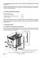
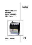
4.1. Overall and assembly dimensions
The RP1 power controller is destined to be mounted on a wall by means of holders.
Power controller overall dimensions, spacing of assembly holes and the fixing
way are presented on the fig. 4.1.
*) Dimensions in parenthesis concern the version
with a fun. Version RPL1- x4xxx (125 A)
6
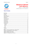
Fig. 4.1. Overall dimensions and fixing way of the RPL1
power controller
In case of mounting in a control cabinet, it is recommended to apply a forced
air cycle.
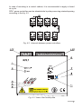
RPL1 power controllers can be situated side by side preserving minimal spacing
according to the fig. 4.2.
Fig. 4.2. Intervals between power controllers
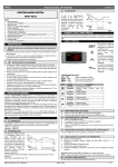
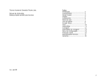
Fig. 4.3 View of the frontal plate
7
Servicing elements are disposed on the power controller frontal plate (Fig. 4.3.)
Signalling diodes:
l
Control
- green diode [1]; power controller readiness to work.
l
Load
- green diode [2]; triggering.
l
Stop
- red diode [3]; external triggering stoppage.
l
Over Temp. - red diode [4], exceeding of the allowable temperature.
l
Fuse fail
- red diode [5], fuse burnout.
Potentiometers and switch:
l
Limit
- potentiometer [6]; limitation of the load current (only for phase
control).
l
Span
- potentiometer [7]; control of the input line amplification (only
for phase control).
l
DIP Switch - DIP-SWITCH [8]; to configure analog inputs and the control
mode.
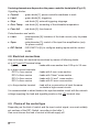
4.2. Electrical connections
One must carry out electrical connections by means of following leads:
a) to LZ1 and LZ2 terminal strips
(fig.4.3),
- leads with cross-section from 0.35 up to 2.5 mm2
b) to high-current terminals:
RPL1-x1xxx version
RPL1-x2xxx version
RPL1-x3xxx version
RPL1-x4xxx version
c) to the protective terminal
- leads with 6 mm2 cross-section
- leads with 10mm2 cross-section
- leads with 16 mm2 cross-section
- leads with 35 mm2 cross-section
- lead with a cross-section at least the same
as leads in high-current circuits
It is recommended to shield leads in the synchronisation circuit with the network
voltage supplying the load and signalling leads on the LZ2 terminal strip.
4.3. Choice of the control type
Depending on the kind of control and the input control signal, one must suitably
set sections of the DIP- Switch, according to the table 1.
One must choose the kind of control at turned supply off.
8
Table 1
DIP switch section
Phase control (ver. RPL1-1xxx)
Input control
signal
Control type
0...5 V
0...10 V
0...20 mA
4...20 mA
So!-Start off
So!-Start on
1
0
0
0
0
2
0
0
0
0
3
1
0
0
0
4
1
1
1
0
5
0
1
DIP switch section
Pulse control (ver. RPL1-2xxx)
Input control
signal
Control type
0...5 V
0...10 V
0...20 mA
4...20 mA
pulse - quick cycle
pulse - slow cycle
relay
1
2
1
1
1
0
1
0
1
3
1
0
0
0
4
5
0
0
0
0
1
1
0
0 – open switch – in position down (OFF),
1 – close switch – in position up (ON),
– State resulting from other settings.
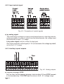
4.4. Connection of control signals
4.4.1. Connection of control to the LZ2 terminal strip
It is recommended to use shielded leads and a separate control and high-current
installation to connect control signals to the LZ2 terminal strip.
Fig. 4.4. Description of the LZ2 terminal strip
9
4.4.2. Input control signal
Fig. 4.5. Connection of control signals
a) by analog signal
The control from a voltage or current control signal source or from the potentiometer is possible. In case of control from the potentiometer, the voltage input
should be set on the 0...5 V range.
b) by pulse signal (only for control of relay type)
One must connect the control signal (4...32 V) to terminals of the voltage input In-U,
set on the 0...5 V range.
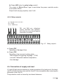
4.4.3. Auxiliary inputs/ outputs
Fig. 4.6. Analog outputs
a) triggering stoppage STOP
One can carry out the triggering stoppage, short-circuiting 5 V and STOP terminals
on the terminal strip. The STOP input is active in the 4...8 V voltage range.
10
b) Output M/S (only for pulse/ relay control)
The output of „Master/Slave” type is used when the power controller works
as a master device.
Output load-carrying capacity: max 5 mA.
4.4.4. Relay outputs
IN = 60 mA/ 230 V a.c./d.c.
Ron = 35 W
Uisol = 1500 VRMS
PK1 and PK2 are voltageless
outputs (MOFSET with optoisolation), they are not protected against
overloads or shortings.
Fig. 4.7. Relay outputs
a) Output PK1
Signalling of damaged fuse
b) Output PK2
Signalling of an incorrect working state:
- active signal of triggering stoppage - STOP,
- exceed of allowable radiator temperature,
- fuse damage.
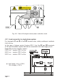
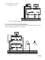
4.5. Connection of supply and load
U1 and U2 high-current sockets to connect supplies of the load circuit, the terminal PE of the protection wire and the fuse B1, are accessible after removing the
protective cover, fig.4.8.
The protective cover is closed by two lateral fasteners.
11
Fig. 4.8. View of the high-current power controller circuit
4.5.1. Load connection in single-phase system
For terminals L1 and N of the LZ1 terminal strip, należy podłączyć zasilanie
230 V/50 Hz.
In the case of phase control (lecture RPL1-1xx) the S1 and S2 terminals
of the synchronisation system should be connected to the load supply circuit.
Depending on the controler version:
230 V a.c. – version RPL1-xx1xx,
400 V a.c. – version RPL1-xx2xx,
500 V a.c. – version RPL1-xx3xx.
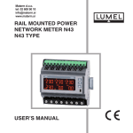
a) Load supply: Uload = 230 V,
UGTS supply = 230 V
12
b) Load supply: Uload = 400 V,
UGTS supply = 230 V
Fig. 4.9. Connection diagramm of load in single-phase system.
4.5.2. Load connection in three-phase system
The power control is possible in the three-wire three-phase system using two
power controllers (only for RPL1-2xx version).
Fig. 4.10 Connection diagram of a load in three-phase system
13
5. DESCRIPTION OF CONTROL TYPES
5.1. Control of ON-OFF type
At the on-off control, the delivered power to the load is described by the following
dependence:
Po =
{
0
for Xin = 0
Po max
for Xin = Xmax
[1]
Where: Po - delivered power to the load
Xin - value of the input control signal
The feed of the voltage signal on the control input, causes the turn of the load
current on. The turn on follows immediately or at the nearest actual supply voltage value transition across zero. Runs of signals describing the power controller
operation for the control of on-off type are shown on the fig. 5.1.
Voltage supplying
the load circuit
Pulse input
signal
turn the across-zero voltage on
Current in the
load circuit
Fig. 5.1. Control of on-off type, runs of occurring signals (for resistive load).
14
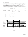
5.2. Pulse control
Pulse control consists on the change of the pulse-duty factor and the frequency
of power P0 delivered to the load in function of the analog control signal, at the
same time the output current is turned on synchronously with the transition of the
supply voltage across zero. Runs of signals are presented on the fig. 5.2.
The power value in the pulse period T according to the formula [2], is defined by
the dependence [3]:
[2]
T = Ts (Non + Noff)
Po = Po max g = Po max
Non
l
where: Ts
g
Non + Noff
= Po max
X in
X in max
[3]
- period of the supply voltage,
- pulse-duty factors,
Non - number of turned periods on,
Noff - number of periods off,
X - value of analog control signal.
Continuous
input
signal
Supplying
voltage
of load circuit
Delivered
power to
the load
Fig. 5.2. Pulse control with a variable pulse frequency, runs of occurring
signals
15
The RPL1 power controller has following kinds of pulse control:
l
Quick cycle, in which for X=1/2 (Xmax - Xmin),
Non = Noff » 25,
l
however fi max » 1 Hz
Slow cycle, in which for X=1/2 (Xmax - Xmin)
Non = Noff » 100,
however fi max » 0.25 Hz
Where: fi max- maximal pulse frequency
Runs of characteristic quantities for the pulse control are presented on the fig, 5.3.
Fig. 5.3. Runs of characteristic quantities for the pulse control.
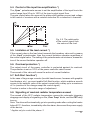
5.3. Phase control
At phase control, a continuous change of delivered power to the load occurs, it
is realised by the change of the load current turn on angle in the function of the
analog control signal.
Runs of signals for this kind of control for a resistive load are presented on the
fig. 5.4.
Continuous
input
signal
Supplying
voltage of
load circuit
current
in the the
load circuit
Fig. 5.4. Phase control, runs of occurring signals
16
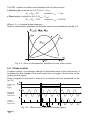
5.4. Control of the input line amplification *)
The „Span” potentiometer serves to set the amplification of the input line in the
control range from 50 up to 100% of the input control signal Xwe.
The gain control takes into account the phase shift between current and voltage
in the control of receivers with a resistive-inductive RL or inductive L character.
Fig. 5.5. The relationship
of the control signal from
the nature of the load.
5.5. Limitation of the load current *)
If the current value in the load circuit exceeds the boundary value set by means
of the „Limit” potentiometer, then the current limitation operates regardless of
the control signal value. The setting of the potentiometer on minimum, means the
turn of the current limitation operation off.
5.6. Overload protection *)
The output circuit of the power controller is protected against its overload.
The protection is set on 125% of the power controller rated current.
The exceed of this value will cause the action of current limitation.
5.7. Soft-Start function*)
In the case of large surge currents (toroidal transformers, furnaces with graphite
lined heaters, etc.), you must enable Soft-Start function, which enables a smooth
access to the setpoint value of the output current with a delay up to a maximum
of 2 s (reaction to the change swept the control signal).
Function is active in the entire range of adjustment.
5.8. Signalling of maximal radiator temperature exceed
The exceed of the 85°C radiator temperature causes the automatic triggering
stoppage and display of signalling on the „Over Temp” diode, and the PK2 relay
turn on.
Note: The driver will automatically go into operating mode after cooling the heater
below 60°C, therefore, immediately after the alarm, disconnect the power supply
of the device.
* Applies only to control the phase. 2
17
6. CONTROLLER OPERATION
In the order please follow these steps:
a) install the power controller,
b) carry out electrical connecitons,
c) set the control type and the input control signal,
d) turn on the supply voltage of the load circuit and of the gate triggering
system
in the case of phase control in addition:
e) set the amplification of the input line*
For resistance load the „Span” potentiometer must be set on maximum.
In case of inductive load, the phase shift between current and voltage must be
taken into consideration, decresing the amplifiaction in such a way as to obtain
current control on the receiver to the full extent of the control signal.
f) set the current limitation*
At the maximal value of the input control signal, set the required current value
increasing the seting on the „Limit ” potentiometer.
*) Getting the right tune using potentiometers shall be achieved experimentally
and should be performed by appropriately trained employee.
18
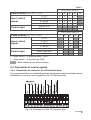
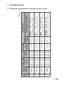
Max.
output
current
25 A
40 A
70 A
125 A
No.
1
2
3
4
230 V / 50 Hz
400 V / 50 Hz
500 V / 50 Hz
230 V / 50 Hz
400 V / 50 Hz
500 V / 50 Hz
230 V / 50 Hz
400 V / 50 Hz
500 V / 50 Hz
230 V / 50 Hz
400 V / 50 Hz
500 V / 50 Hz
5.7 kW
10.0 kW
12.5 kW
9.2 kW
16.0 kW
20.0 kW
16.0 kW
28.0 kW
35.0 kW
28.0 kW
50.0 kW
62.0 kW
< 215 W
< 120 W
< 65 W
< 40 W
Supply voltage
Lost power
Max. load
in
of the load
power
thyristors
circuit
35 (40) A
35FE – Bussmann
6.9 gRB 000 BS 88/40 – FERRAZ
50 A
50FE – Bussmann
6.9 gRB 000 BS 88/50 – FERRAZ
100 A
100FE – Bussmann
6.9 URB 000 BS 88/100 – FERRAZ
160 (200) A 200FEE – Bussmann
6.9 URB 000 BS 88/160 – FERRAZ
440 A2s
3600 A2s
9600 A2s
Designation and manufacture
280 A2s
i2 dt
at 415 V
Fuse parameters
Table 2
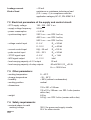
7. TECHNICAL DATA
7.1 Electrical parameters of the high-current circuit
19
Leakage current
< 20 mA
Kind of load
resistance or resistance-inductance load
(0.2 < cosj <1) in compliance with the
application category AC-51, EN 60947-4-3
7.2 Electrical parameters of the supply and control circuit:
- GTS supply voltage
- supply voltage frequency
195...230...253 V a.c.
50 Hz
- power consumption
£ 4.5 VA
- synchronizing input
230 V a.c. - ver. RPL1-xx1xx,
400 V a.c. - ver. RPL1-xx2xx,
500 V a.c. - ver. RPL1-xx3xx,
- voltage control input
0...5 V
Rin = 20 kW
0...10 V
Rin = 40 kW
- current control input
0(4)...20 mA
Rin =125 W
- pulse control input
0/4....32 V
Rin = 20 kW
- STOP signal input
4...8 V
Rin = 1 kW
- M/S signal output
6...12 V
labil
- load-carrying capacity of 5 V output
- load-carrying capacity of relay outputs
25 mA
60 mA/350 V, Ron =35 W
Uizol = 1500 VRMS
7.3. Other parameters:
- working temperature
- storage temperature
- humidity
- working position
- dimensions:
- weight
0... 40°C
- 25... 55°C
< 90% (without condensation)
vertical
135 x 201 x 199 mm
135 x 231 x 199 mm - ver. RPL1-x4xx (version
with a fan)
4.5 kg
5.0 kg - ver. RPL1-x4xx (version with a fan)
7.4. Safety requirements:
- maximal phase-to-earth
working voltage
20
320 V for power and supply circuits,
50 V for other circuits
- pollution degree
- installation category
- protection degree from
terminal side
- housing protection degree
2
III
IP 10, acc. to EN 60529
IP 20, acc. to EN 60529
7.5. Electromagnetic compatibility:
- immunity noise
- emission noise
EN 60947-4-3
EN 60947-4-3
The RPL1 power controller fulfils requirements of the EN 60947-4-3 standard.
NOTE: In case of phase control, the power controller fulfils requirements of the
electromagnetic compatibility in relation to the interference emission, only
when working near the of the supply voltage through zero.
21
8. ORDERING CODES
Table 3
RPL1 - X
X
X XX X
X
Control:
phase
pulse / on/off
1
2
Current range:
maximal output current 25 A
maximal output current 40 A
maximal output current 70 A
maximal output current 125 A*
1
2
3
4
Load voltage:
supply voltage
supply voltage
supply voltage
- 195...230...253 V a.c.
- 340...400...440 V a.c.
- 425...500...550 V a.c.
1
2
3
Version:
standard
custom-made**
00
XX
Language:
Polish
English
other**
P
E
X
Acceptance tests:
without additional quality inspection requirements
with an extra quality inspection certificate
other requirements**
0
1
X
* the version RPL1- x4xx has a fixed fan
** after agreeing with the manufacturer
Ordering example:
The code: RPL1 - 1 - 1 - 2 - 00 - E - 0 means:
RP1 - power controller of RPL1 type
1 - phase control
1 - output current maximal 25 A
2 - supply voltage -340...400...440 V a.c.
00 - standard version
E - English
0 - without additional quality inspection requirements.
22
9. MAINTENANCE AND WARRANTY
The RPL1 power controller does not require any special periodical maintenance.
In case of replacement of the damaged fuse, you must:
- disconnect the power supply of the power controller from power clamp
and LZ1 terminal,
- remove the cover, fig. 4. 10,
- replace fuse B1, type according to the table 2.
In case of some incorrect operations:
After the dispatch date and within the period stated in the warranty card
One should return the power controller to the Manufacturer’s Quality Inspection Dept. If the device has been used in compliance with the instructions, the
Manufacturer warrants to repair it free of charge. The disassembling of the
housing causes the cancellation of the granted warranty.
After the warranty period:
One should send the device to repair it in an authorized service workshop. Spare
parts are available for the period of five years from the date of purchase.
Our policy is one of continuous improvement and we reserve the
right to make changes in design and specifications of any products
as engineering advances or necessity requires and revise the
above specifications without notice.
23
LUMEL S.A.
ul. Słubicka 1, 65-127 Zielona Góra, Poland
Export Department:
Tel.: (48-68) 45 75 302
Fax: (48-68) 32 54 091
e-mail: [email protected]
P41-09
Tel.: (48-68) 45 75 100
Fax: (48-68) 45 75 508
e-mail:[email protected]
http://www.lumel.com.pl