1
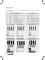
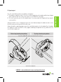
Manuale di istruzioni per l’uso ISTRUCTION MANUAL MODE D’EMPLOI BEDIENUNGSANLEITUNG MANUAL DE INSTRUCCIONES Инструкция по монтажу INDICE 1. Informazioni generali 1.1 Introduzione al presente manuale pag. 3 2. pag. 3 Sicurezza 3. Dati tecnici 3.1 Tabella dati tecnici e Marcatura CE pag. 5 4. 4.1 4.2 4.3 pag. 6 Attuatore Tipologie di alimentazione Calcolo della forza necessaria Confezione e strumenti necessari per il montaggio dell’attuatore 5. Installazione 5.1 Seguenza d’installazione 5.2 Collegamento elettrico pag. 7 6. Manutenzione, manovre di emergenza, pulizia pag. 16 7. Protezione dell’ambiente pag. 17 8. 9. FAQ (domande frequenti) pag. 17 Garanzia pag. 18 10. Dichiarazione “CE” di conformità 2 pag. 19 ITALIANO 1. INFORMAZIONI GENERALI 1.1 Introduzione al presente manuale Leggere attentamente e rispettare le istruzioni riportate nel manuale. Conservare il presente manuale per l’utilizzo e la manutenzione futuri. Prestare attenzione alla configurazione dei dip-switch, ai dati relativi alle prestazioni (vedi “Dati tecnici”) e alle istruzioni d’installazione. L’utilizzo improprio o il funzionamento/montaggio non corretti possono danneggiare il sistema nonché oggetti e/o persone. Le istruzioni di montaggio sono disponibili anche sul sito internet ufficiale http://www.comunello.com/mowin 2. SICUREZZA Il presente manuale di installazione è rivolto esclusivamente a personale professionalmente competente. L’installazione, i collegamenti elettrici e le regolazioni devono essere effettuati nell’osservanza della Buona Tecnica e in ottemperanza alle norme vigenti. Leggere attentamente le istruzioni prima di iniziare l’installazione del prodotto. Una errata installazione può essere fonte di pericolo. I materiali dell’imballaggio (plastica, polistirolo, ecc.) non vanno dispersi nell’ambiente e non devono essere lasciati alla portata dei bambini in quanto potenziali fonti di pericolo. Prima di iniziare l’installazione verificare l’integrità del prodotto. Se il cavo di alimentazione è danneggiato, esso deve essere sostituito dal costruttore o dal suo servizio di assistenza tecnica o comunque da una persona con qualifica similare, in modo da prevenire ogni rischio. Non installare il prodotto in ambiente e atmosfera esplosivi: presenza di gas o fumi infiammabili costituiscono un grave pericolo per la sicurezza. Prima di installare la motorizzazione, apportare tutte le modifiche strutturali relative alla realizzazione dei franchi di sicurezza ed alla protezione o segregazione di tutte le zone di schiacciamento, cesoiamento, convogliamento e di pericolo in genere. Verificare che la struttura esistente abbia i necessari requisiti di robustezza e stabilità. Il costruttore della motorizzazione non è responsabile dell’inosservanza della Buona Tecnica nella costruzione degli infissi da motorizzare, nonché delle deformazioni che dovessero intervenire nell’utilizzo. Applicare le segnalazioni previste dalle norme vigenti per individuare le zone pericolose. Verificare che la rete di distribuzione elettrica non sia da “cantiere” ma sotto apposite cabine, in caso di dubbio o assenza d’informazioni (certe) prevedere anche: - trasformatori d’isolamento appositi; - interruttori magnetotermici adeguati al carico di tensione richiesta; - scaricatori di sovratensione. Prima di collegare l’alimentazione elettrica accertarsi che i dati di targa siano rispondenti a quelli della rete di distribuzione elettrica. Prevedere sulla rete di alimentazione un interruttore/sezionatore onnipolare con distanza d’apertura dei contatti uguale o superiore a 3 mm. 3 Verificare che a monte dell’impianto elettrico vi sia un interruttore differenziale e una protezione di sovracorrente adeguati. Quando richiesto, collegare ad un efficace impianto di messa a terra eseguito secondo le vigenti norme di sicurezza del paese in cui l’attuatore viene installato. Prima di effettuare qualsiasi intervento (installazione, manutenzione e riparazione) togliere l’alimentazione prima di agire sull’apparecchiatura. Per assicurare un’efficace separazione dalla rete si consiglia di installare un pulsante bipolare di tipo approvato. Gli attuatori in bassa tensione 24 Vdc devono essere alimentati da appositi alimentatori (NO TRASFORMATORI) omologati di classe II (doppio isolamento di sicurezza) avente tensione d’uscita di 24 Vdc -15% ÷ +20% (ovvero 20,4 Vdc min - 28,8 Vdc max). Utilizzando la versione 24Vdc è necessario che il cavo abbia una sezione idonea, calcolata in base alla distanza tra alimentatore e attuatore, in modo da non avere cadute o dispersioni di tensione. Sezione dei cavi 1,50 mm² 0,75 mm² Lunghezza max del cavo ~ 100 m ~ 50 m L’apparecchio non è destinato a essere usato da persone (bambini compresi) le cui capacità fisiche, sensoriali o mentali siano ridotte, oppure con la mancanza di esperienza o di conoscenza, a meno che esse abbiamo potuto beneficiare, attraverso l’intermediazione di una persona responsabile della loro sicurezza, di una sorveglianza o di istruzioni riguardanti l’uso dell’apparecchio. I bambini devono essere sorvegliati per sincerarsi che non giochino con l’apparecchio. L’attuatore a catena Liwin è destinato solo ed esclusivamente all’uso per il quale è stato concepito ed il costruttore non può essere ritenuto responsabile per danni dovuti ad un uso improprio. L’attuatore è destinato esclusivamente all’installazione interna per aprire e chiudere finestre a sporgere, a vasistas, abbaini, cupole e lucernai. Ogni altro impiego è sconsigliato salvo preventivo benestare del costruttore. L’installazione dell’attuatore va effettuata seguendo le istruzioni riportate nel presente manuale. Il mancato rispetto di tali raccomandazioni può compromettere la sicurezza. Ogni eventuale dispositivo di servizio e comando dell’attuatore deve essere prodotto secondo le normative in vigore e rispettare le normative in materia emanate dalla Comunità Europea. In caso di installazione dell’attuatore su una finestra posta ad un’altezza inferiore a 2,5 m dal pavimento e in edifici (pubblici e non) dove non è chiaro l’uso di destinazione, l’attuatore deve essere azionato solo ed esclusivamente da un comando non accessibile al pubblico (pulsante con chiave). Il comando deve: 1) essere posizionato ad un’altezza minima di 1500 mm dal pavimento e 2) essere posizionato in modo tale che all’attivazione, la persona addetta all’apertura/chiusura abbia entro il proprio campo visivo tutte le parti in movimento. Non lavare l’apparecchio con solventi o getti d’acqua. Non immergere l’apparecchio in acqua. Ogni riparazione deve essere eseguita da personale qualificato (costruttore o centro d’assistenza autorizzato). Richiedere sempre ed esclusivamente l’impiego di ricambi originali. Il mancato rispetto di ricambi originali può compromettere il corretto funzionamento del prodotto e la sicurezza di persone e cose, annullando inoltre i benefici della garanzia allegata all’apparecchio. Nel caso di problemi o incertezze, rivolgersi al punto vendita in cui è stato acquistato il prodotto o direttamente al produttore. 4 ITALIANO 3. DATI TECNICI 3.1 Tabella dati tecnici e marcatura Il marchio CE attesta che l’attuatore è conforme ai requisiti essenziali di sicurezza e di salute previste dalle direttive Europee di prodotto. Il marchio CE è individuabile tramite apposita targhetta adesiva applicata esternamente il prodotto, in cui sono indicati alcuni dei dati presenti nella tabella a seguire: Liwin 2W-Net Liwin 3W-Net Liwin 4W-Net Liwin Modello L35 230Vac Modello L35 24Vdc Modello L25 110-230Vac Alimentazione elettrica VAC Alimentazione elettrica VDC Frequenza Servizio Forza di spinta/trazione L35 *** Forza di spinta/trazione L25 Velocità di traslazione a vuoto Grado di protezione Doppio isolamento AC Doppio isolamento DC Assorbimento VAC L35 Assorbimento VAC L25 Assorbimento VDC Potenza L35 Potenza L25 Temperatura di funzionamento Corse L35 Corse L25 Finecorsa in chiusura Soft Start/Soft Stop Rilevamento ostacoli Collegamento in parallelo Sincronizzazione Dimensioni Liwin R Liwin 2W-Net R Liwin 3W-Net R Liwin 4W-Net R ML35S140Hy00* ML35S140Ly00* ML25S138Iy00* 110(solo L25)-230 Vac 24 Vdc 50 /60 Hz 350 N 250 N 0,19 A 0,14 A 1A 28 W 22 W si / si si no ML35Sx40Hy00** ML35R140Hy00* ML35Rx40Hy00** ML35Sx40Ly00** 230 Vac 230 Vac 230 Vac 24 Vdc 50 Hz 50 Hz 50 Hz S2 4 min 350 N 350 N 350 N 18 mm/s IP44 si bassa tensione 0,19 A 0,19 A 0,19 A 1A 28 W 28 W 28 W -5 / +50 °C 50 – 100 – 150 – 200 – 250 – 300 – 350 – 400 – 420 mm 200 – 250 – 380 mm per assorbimento si / si si / si si / si si si si si ( max 30 attuatori ) si no si 390x38x73 mm * Sostituire y con il valore colore: 0B nero, 0W bianco, 0G grigio. ** Sostituire x con il valore sincronizzato: 2 = due attuatori, 3 = tre attuatori, 4 = quattro attuatori. *** Nei sistemi Liwin 2-3-4 Wnet e 2-3-4 Wnet R, la forza di spinta /trazione totale, va calcolata togliendo il 30% della somma delle forze dei singoli attuatori (350 N) . 5 4. ATTUATORE C 4.1 Tipologie di alimentazione L’attuatore Liwin è disponibile in vari modelli e colori in due versioni di alimentazione elettrica: F • 110(solo L25)-230 Vac - può essere alimentato con tensione di rete 110(solo L25)-230 Vac (50 /60 Hz) (tolleranza ±10%), con cavo d’alimentazione a tre fili: AZZURRO, comune neutro; NERO, fase apre; H (B) MARRONE, fase chiude. • 24 Vdc - può essere alimentato con tensione di 24 Vdc con cavo d’alimentazione a due fili: AZZURRO, C connesso al + (positivo) chiude; MARRONE, connesso al + (positivo) apre. P 4.2 Calcolo della forza necessaria F Simbologia F = Forza richiesta per l’apertura, unità di misura N (Newton) P* = Peso della finestra solo parte apribile, unità di misura Kg (chilogrammi) C = Corsa di apertura dell’attuatore, unità di misura cm (centimetri)(B) F apribile, unità di misura cm (centimetri) H = Altezza della finestra solo parte * Nel caso di cupole o lucernai orizzontali,considerare il carico della neve. P Finestra a vasistas Finestra a sporgere H P Cupole o lucernai orizzontali C (A) F H (B) H F P F P P C F = [(P / 2 ) x (C/H)] x 9.8 F = [(P / 2 ) x (C/H)] x 9.8 F = (P / 2) x 9.8 4.3 Confezione e strumenti necessari per il montaggio dell’attuatore (A) F L’attuatore è imballato singolarmente in scatola di cartone. Ogni confezione contiene: L25)-230 Vac 50/60 Hz oppure a 24 Vdc con cavo di alimentazione elettrica, staffa di attuatore elettrico 110(solo H P supporto, staffa di attacco per apertura a vasistas/sporgere, dima di foratura e manuale istruzioni.PPrima di iniziare il montaggio dell’attuatore si consiglia di preparare il seguente materiale di completamento, attrezzi e utensili. Metro o flessometro, matita, trapano/avvitatore, set di punte da trapano per metallo o legno, setFdi inserti per avvitare, forbici da elettricista, giraviti, viti e/o inserti filettati idonei alla tipologia del materiale del serramento. C È SCONSIGLIATO, su qualsiasi serramento metallico, l’uso di viti autoperforanti e/o viti trilobate. (A) 6 H P F C ITALIANO 5. INSTALLAZIONE Su serramenti con apertura a vasistas c’è il pericolo di lesioni prodotte dalla caduta accidentale della finestra. È OBBLIGATORIO il montaggio di bracci limitatori (tipo serie 1276) o un sistema di sicurezza alternativo, dimensionato opportunamente per resistere all’eventuale caduta accidentale della finestra. Non far rientrare la catena prima di averla fissata al serramento. Apertura a sporgere: Ingombri e fori di fissaggio 37 37 38.5 38.5 17.5 17.5 10 10 54.4 54.4 Filo Serramento Serramento Filo 27 27 325 325 414 414 27 27 99 99 Apertura a vasistas: Ingombri e fori di fissaggio 27 27 106.3 106.3 Filo Serramento Serramento Filo 41 41 55 55 74.5 74.5 414 414 325 325 74.5 74.5 55 55 32.5 32.5 27 27 99.5 99.5 5.1 Sequenza d’installazione - Verificare che la larghezza del serramento, dove è previsto il montaggio dell’attuatore, sia superiore a 420 mm. In caso contrario NON È POSSIBILE montare l’attuatore. - Verificare che la forza necessaria all’apertura/chiusura (calcolata secondo la tabella al punto 4.2) sia inferiore o uguale a quella indicata nella TABELLA DATI. - Verificare manualmente l’apertura dell’anta, controllando ed eliminando eventuali zone d’impuntamento che possano dare luogo a mal funzionamenti. - Verificare manualmente l’apertura massima dell’anta controllando che sia maggiore della corsa da impostare sull’attuatore. 7 Apertura a vasistas: Tipologia Apertura a sporgere Tipologia ATTENZIONE Se l’apertura è a vasistas verificare che siano presenti i bracci limitatori per resistere all’eventuale caduta accidentale della finestra. Apertura vasistas: Tracciare con la matita la mezzeria “X” del serramento. Apertura a sporgere: Tracciare con la matita la mezzeria “X” del serramento. m m 0m 0m = 42 m = in m 42 = Min m M420 in m m = =42020m M = m =0m MMinin 4 = 42= in == M mm 0 = = 42 Min = Min = in mM 0m = m 0m = = Min 42 Apertura a vasistas: accessori da utilizzare e êtr / fen w do tra es fin aio / win me dre ón az n/ arm n/ arm 42 0m = m 42 0m = m me / rah / ca / fra tel ón me dre me aio ing tel ere en org op a sptward ne tra ou es ng alien Fin hu à l’it te pr To tre ste tan nê jec Fe ppfenpro Kla na nta Ve ing en tas op sis ard a va inw tra ng et es hu uffl Fin m-à so tto Bo tre ter ble nê Fe pfensabati Kip na nta Ve / fra tra es fin 42 Apertura a Minsporgere: accessori da utilizzare = Min na nta ve r/ ste / fen = Min =420 0 = Min mm = = mm 42 0m = Min= Min4 = m 2 = 402Mmin = Min 0 mm42 = 42 m0m = 0 =m = m m 42 / ca w do / rah e/ êtr / fen az r/ ste fen na nta ve Fin To estra pFe hu a sp nê ng Klap tre ou orge tw re Ve pfenà l’it ar ntan ste ali d op en a pr r ne ening oje ctan te / win Fin Bo estra tto Fe m a va nê -h Kipp tre un sista g s Ve fensà so inw ntan te uf ar fle d op a abr t en atibl ing e fin es tra tel aio / wi nd ow / fra me / fen êtr / ca dre e/ fen ste / ra r/ hm en / ar ve nta ma na zó n tel aio fin es / fra tra me / wi / ca nd ow dre / ra / fen hm en êtr e/ / ar ma fen ste r/ 8 zó ve n nta na 2 =0 n Mi Min 04mmin 42 42 M = = Min= = = ITALIANO = = == Min =Min M Min 420 in 4422=0 m 0 m == 42 0 m =m mm m m Apertura a vasistas Apertura a sporgere Attaccare la dima adesiva al serramento. r/ ste fen e/ êtr / fen ow nd tra es fin / wi me dre en na nta ve n zó ma / ar hm / ra / ca / fra aio tel dre me tel tra es fin / ca ow en / ar hm / ra r/ ste na nta ve fen e/ êtr / fen nd / wi Fine To stra pFe hu a sp nê ng Klap tre ou orge tw re Ve pfenà l’it ar ntan st ali d op en a pr er ne ening ojec tant e Fine Bo stra tto Fe m a va nê -h Kipp tre un sista g s Ve fensà so inw ntan te uf ar fle d op a abr t en atib ing le fin es tra telai / wi nd o/ ing en / fra aio re ening ge or d op a sptwarne tra ou es ng alien Fin hu à l’it te pr To tre ste ctan nê Fe pfenproje Klapana nt Ve tas op sis ard a va inw tra ng et es hu uffl Fin m-à so tto Bo tre r ible nê ste Fe fen abat Kippana nt Ve n zó ma ow fra me / fe nê / ca tre dre / fe / ra ns hm en ter / ar / ve ntan maz a ón telai o/ fin es fra me tra / wi / ca nd ow dre / ra hm / fe en nê tre / fe / ar maz ns ter ón / ve ntan a Forare il serramento utilizzando o la dima in dotazione o le quote indicate a pagina 7. Fissare le staffe e gli attacchi utilizzando viti idonee. r/ ste fen e/ êtr / fen ow nd tra es fin aio / wi me dre en na nta ve n zó ma / ar hm / ra / ca / fra tel en dre me aio re ening ge or d op a sptwarne tra ou es ng alien Fin hu à l’it te pr To tre ste ctan nê Fe pfenproje Klapana nt Ve ing en tas op sis ard a va inw tra ng et es hu uffl Fin m-à so tto Bo tre r ible nê ste Fe fen abat Kippana nt Ve n zó ma tel / fra tra es fin / ca ow / rahm e/ / ar ste fen Fine Bo stra tto Fe m a va nê -h Kipp tre un sista g s Ve fensà so inw ntan te uf ar fle d op a abr t en atib ing le êtr / fen nd / wi Fine To stra pFe hu a sp nê ng Klap tre ou orge tw re Ve pfenà l’it ar ntan st ali d op en a pr er ne ening ojec tant e na nta ve r/ fin es tra telai / wi nd o/ ow fra me / fe nê / ca tre dre / ra / fe ns hm en ter / ar / ve ntan maz a ón telai o/ fin fra es tra me / wi / ca nd ow dre / ra hm / fe en nê tre / fe / ar maz ns ter ón / ve ntan a a / ter ntan ve ns ón / fe maz tre / ar nê en / fe hm ow ra nd e/ / wi dr tra / ca es me fin / fra io tela ón maz e/ dr me io re ge or d op a sptwar e nn strang outalie e Fine hu à l’i nt pTo tre sterecta nê en Fe pf proj ap a Kl an nt Ve tela ing en ing as sistward a vag in t stra-hun uffle m so Fine tto à Bo tre ter ible nê ns at Fe fe ab pp a Ki an nt Ve en op tra es fin / fra / ca ow nd / wi en hm ra tre nê / fe / ar ter a ntan / ve ns / fe Fine To stra pFe hu a sp nê ng Kl tre ou orge ap Ve pf à l’i twar re nt en ta an ster lie d op nn en a pr e ing ojec ta nt e Fine Bo stra Fe ttom a va nê Ki tre-hun sist pp as Ve fe à sog inw nt nste uf ar an a abr flet d op en at ing ible fin es tra tela io /w indo / fra me w / fe nê / ca dr e/ tre ra / fe ns hm en ter / ar / ve ntan maz a ón tela io fin es / fra tra me / ca dr e/ indo ra hm w / fe en nê / ar tre maz / fe ón ns ter / ve ntan /w a 9 Apertura a vasistas Apertura a sporgere Inserire il perno di fulcro laterale nella staffa di supporto Spostare l’attuatore verso il serramento in modo da inserire il perno dei fulcro laterale (opposto) nella staffa di supporto. Ruotare l’attuatore, come da figura a seguire, per l’aggancio definitivo. 10 ITALIANO Apertura a vasistas Apertura a sporgere Ruotare l’attuatore in modo da permettere al serramento di chiudere. Ruotare l’attuatore nel senso opposto al precedente in modo che il terminale catena possa inserirsi perfettamente all’interno dell’attacco. Unire la catena all’attacco inserendo l’apposito innesto. Agganciare la clip di copertura. 11 Apertura a vasistas Apertura a sporgere Rimozione testata e tappo in gomma. Posizione Dip-Switch. 12 Liwin 350N Corsa 420 400 350 300 250 200 150 Dip-switch 1 Dip-switch 2 Corsa Dip-switch 1 Dip-switch 2 Alto Alto Medio Medio Basso Basso Basso Alto Alto Alto Medio Medio Basso Basso Alto Alto Medio Medio Basso Alto Medio Medio Basso Basso Alto Alto Medio Medio Basso Basso Alto Alto Medio Medio Basso Basso Alto Alto Medio Medio Basso Basso Alto Alto Medio Medio Basso Basso Alto Alto Medio Medio Basso Basso 100 50 Liwin 250N Corsa Dip-switch 1 Dip-switch 2 Alto 200 Medio Assente Basso Alto 250 Medio Assente Basso Alto 380 Medio Assente Basso 13 ITALIANO Selezionare la corsa desiderata, seguendo il settaggio dei dip-switch secondo lo schema a seguire. Attenzione ogni dip-switch ha 3 (tre) possibili posizioni. 5.2 Collegamento elettrico Cablare l’apparecchiatura secondo la tensione richiesta dall’attuatore (vedi Etichetta sul prodotto) seguendo lo schema riportato di seguito. Alimentazione 110(solo L25)-230 Vac Blu Neutro / Comune 1 Blu 2 Nero Fase / Apre 2 Marrone Negativo Positivo 3 Marrone Fase /Chiude 4 Bianco Dati (versioni 2/3/4 W-Net) 4 Bianco Dati (versioni 2/3/4 W-Net) 5 Giallo Dati (versioni 2/3/4 W-Net) 6 Verde Dati (versioni 2/3/4 W-Net) 5 Giallo Dati (versioni 2/3/4 W-Net) 6 Verde Dati (versioni 2/3/4 W-Net) Cablaggio elettrico 230 Vac 4 1 Alimentazione 24 Vdc 1 3 5 1 2 6 3 4 4 5 5 6 6 1 Cablaggio versione radio Cablaggio elettrico 24Vdc 2 1 1 3 1 2 N N 110(solo L25)~50/60HZ 110/230V~ 230V~ 50Hz 50/60Hz F F 24 Vdc Cablaggio elettrico 230 Vac (versioni 2/3/4 W-Net) 1 2 + 230V~ 50Hz N 110/230V~ 50/60Hz F N F Cablaggio versione radio (versioni 2/3/4 W-Net) Cablaggio elettrico 24 Vdc (versioni 2/3/4 W-Net) 4 4 4 4 4 4 4 4 5 5 5 5 4 5 4 55 4 5 5 5 5 5 6 6 6 6 5 6 5 66 5 6 6 6 6 6 1 3 1 2 3 44 + - 24 Vdc 4 N 110/230V~ 50/60Hz F 230V~50HZ 14 2 3 4 6 1 6 2 3 1 6 + 24 Vdc230V~ 50Hz - N N 110/230V~ 50/60Hz F F 13 2 24 Vdc 230V~ 50Hz N+ F- Premere sul pulsante di comando ed effettuare una chiusura verificando che: A. Il serramento raggiunga la completa chiusura. Se così non fosse verificare che il sormonto tra anta e telaio sia maggiore o uguale a 0 mm. Eventualmente inserire degli spessori in modo da ripristinare il sormonto corretto. B. La catena sia perfettamente perpendicolare al serramento. Eventualmente regolare la staffa di attacco agendo su viti ed asole. Raggiunta la corretta posizione di chiusura premere sul pulsante di comando ed effettuare un’apertura al fine di verificare che l’attuatore svolga tutta la corsa impostata liberamente. Raggiunta l’apertura desiderata ri-premere il pulsante di comando ed effettuare la chiusura. Una volta che la finestra ha raggiunto la completa chiusura verificare che le viti, dei supporti e degli attacchi, siano correttamente serrate e che le guarnizioni siano adeguatamente compresse. Apertura a vasistas Apertura a sporgere Inserire il tappo in gomma copri dip-switch e richiudere la testata. Installazione completata Attenzione!! - è obbligatorio al termine dell’installazione che i 4 coperchi siano perfettamente chiusi. 15 ITALIANO 5.3 Test di funzionamento ATTENZIONE! Prima di azionare l’attuatore, verificare sempre che il prodotto sia agganciato nella posizione corretta OK no 2mm 6. MANUTENZIONE, MANOVRE DI EMERGENZA, PULIZIA Nel caso sia necessario manualmente sganciare il serramento dall’attuatore a causa di: mancanza di tensione, avaria del meccanismo, manutenzione, pulizia esterna del serramento; è necessario eseguire la sequenza (pagg. 11) in modo inverso. ATTENZIONE PERICOLO di caduta della finestra; l’anta è libera di cadere perché non è più tenuta dalla catena. Una volta effettuata la manutenzione e/o la pulizia ripetere la sequenza di pagina 11. 16 8. FAQ (domande frequenti) Domanda Causa Assenza di tensione L’attuatore non funziona ? L’attuatore non effettua la corsa desiderata Soluzione Verificare che lo stato del salvavita o dell’interruttore di sicurezza sia su ON (acceso). Probabile cavo non collegato. Controllare i collegamenti elettrici che vanno dall’interruttore all’attuatore. Tensione presente Verificare che il voltaggio dell’attuatore sia coerente con la tensione rilevata. L’ampiezza di apertura non è quella desiderata Verificare secondo la tabella di pagina 13 che il settaggio dei dip-switch sia impostato sulla corsa desiderata. La catena è curvata e non perfettamente lineare Sganciare la catena dall’attacco e verificare che il braccio limitatore permetta la corsa completa all’attuatore. Se ciò non dovesse essere regolare il braccio limitatore in modo che l’attuatore effettui tutta la corsa. Verificare di aver utilizzato fissaggi idonei. L’attuatore ha strappato le viti Gli attacchi (vasistas e/o sporgere) non sono più fissati al serramento. Verificare che alla chiusura la catena sia perfettamente perpendicolare al serramento. Se ciò non dovesse essere, verificare che il montaggio sia stato effettuato secondo la sequenza 5.1. 17 ITALIANO 7. PROTEZIONE DELL’AMBIENTE L’attuatore al proprio interno contiene particolari non riciclabili (materiali plastici e particolari elettronici) che non fanno parte dei normali rifiuti. Devono essere smaltiti adeguatamente. Per qualsiasi dubbio, contattate la società che si occupa dello smaltimento rifiuti. 9. GARANZIA Fratelli Comunello SpA garantisce, a condizione del rispetto delle specifiche prestazionali indicate nei manuali di istruzione dei prodotti, il corretto funzionamento degli attuatori per trentasei mesi dalla data di fabbricazione. Fratelli Comunello S.p.a. garantisce in via esclusiva, e quindi con esclusione di domande risarcitorie formulate per equivalente, la riparazione o sostituzione gratuita delle parti difettose che verranno riconosciute tali, secondo l’insindacabile giudizio tecnico del personale di Fratelli Comunello SpA. Il materiale in garanzia inviato alla sede della Fratelli Comunello SpA, dovrà essere spedito in porto franco e verrà quindi rispedito in porto assegnato. Il materiale ritenuto difettoso ed inviato a Fratelli Comunello S.p.a. rimarrà di proprietà di quest’ultima società.Il costo di manodopera necessario per le riparazioni e sostituzioni eseguite rimane a carico dell’acquirente. Non viene riconosciuto alcun indennizzo per il periodo d’inoperatività dell’impianto. L’intervento non prolunga la durata della garanzia. A pena di decadenza, l’acquirente deve denunciare gli eventuali vizi e difetti dei prodotti, entro il termine di 8 (otto) giorni da calcolarsi rispettivamente dalla data di scoperta dei vizi o dalla data di consegna della merce. La denuncia dovrà essere fatta esclusivamente per iscritto. La garanzia non comprende: Avarie o danni causati dal trasporto; avarie o danni causati da vizi dell’impianto elettrico presente presso l’acquirente il prodotto e/o da trascuratezza, negligenza, inadeguatezza, uso anomalo di tale impianto; avarie o danni dovuti a manomissioni poste in essere da parte di personale non autorizzato o conseguenti allo scorretto uso/installazione (a questo proposito, si consiglia una manutenzione del sistema almeno ogni sei mesi) o all’impiego di pezzi di ricambio non originali; difetti causati da agenti chimici e/o fenomeni atmosferici. La garanzia non comprende il costo per materiale di consumo né quello per vizi presunti o verifiche di comodo. Caratteristiche dei prodotti I prodotti realizzati da Fratelli Comunello SpA sono soggetti a continue innovazioni e miglioramenti; pertanto, le caratteristiche costruttive e l’immagine degli stessi, potranno subire variazioni anche senza preavviso. Foro competente Poiché il contratto viene perfezionato mediante Conferma d’Ordine compilata in Rosà, in caso di controversia legale di qualsiasi natura è applicabile il diritto italiano ed è competente il Foro di Bassano del Grappa (VI). 18 ITALIANO CONTENTS OF MANUAL 1. General Information 1.1 Introduction to this manual page 3 2. page 3 Safety 3. Technical Data 3.1 Table of technical data and CE mark page 5 4. 4.1 4.2 4.3 page 6 Actuator Types of power supply Calculation of the force necessary Pack and tools required for assembling the actuator 5. Installation 5.1 Installation sequence 5.2 Electrical connection page 7 6. Maintenance, Emergency Action & Cleaning page 16 7. Protection Of The Environment page 17 8. FAQ (frequently asked questions) page 17 9. Guarantee page 18 10. “CE” Declaration Of Conformity 2 page 19 1.1 Introduction to this manual Please read carefully and follow the instructions detailed in this manual. Keep the manual for use and future maintenance. Pay attention to the configuration of the DIP-switches, to the data concerning the performance (see “Technical Data”) and to the installation instructions. Improper use or incorrect operation, fitting or assembly can damage the system as well as cause injury to people and damage to property. The assembling instructions are available on the official web site http://www.comunello.com/mowin 2. SAFETY This installation manual is written exclusively for competent professional personnel. The installation, electrical connections and adjustments must be carried out conforming to good practice and according to the regulations in force. Incorrect installation can cause a potential hazard. The packing materials (plastic, polystyrene, etc.) must not be allowed to pollute the environment, but must be disposed of correctly, and must not be left within the reach of children since they can cause possible hazards. Before starting installation, check the product is complete and undamaged. If the power cable is damaged, it must be replaced by the manufacturer or his technical support or a similarly qualified person in order to avoid any risks. Do not install the product in an explosive environment or atmosphere: the presence of flammable gas or fumes is a serious health and safety hazard. Before installing the drive mechanism, put in place all the structural modifications relating to safety measures and to the protection or segregation of all the zones involving hazards of crushing, shearing, entrapment and of general hazard. Check that all the existing structure has the necessary requirements of strength and stability. The manufacturer of the drive mechanism is not responsible for failing to conform to good practice in the construction of the windows to be opened, as well as any distortion which could occur during use. Put up the notices laid down by current regulations to identify hazardous areas. Ensure that the electrical supply is not a temporary one, but has the required electrical boxes, and in case of doubt or lack of (definite) information, also install: - suitable isolating transformers; - thermal magnetic cut-outs suitable to voltage requirements; - surge arrester. Before connecting the electrical supply, ensure that the electrical rating correspond to that of electrical distribution supply. Fit onto the supply network an allpole switch with a contact gap of at least 3 mm. 3 ENGLISH 1. GENERAL INFORMATION Check that on the supply side of the electrical plant there is a suitable differential residual current circuit breaker and overload protection. When required to do so, connect to an efficient earthing/ground system fitted according to the safety regulations in force in the country where the actuator is being installed. Before carrying out any operation (installation, maintenance or repair), isolate the electrical supply before working on the equipment. To ensure complete isolation from the supply current, installation is recommended of a double-pole switch of the approved type. The low-voltage 24 Vdc actuators must be supplied by suitable power supplies (NOT TRANSFORMERS) of an approved Class II type (double safety insulation) having an output voltage of 24 Vdc -15% to +20% (or from 20.4 Vdc min. to 28.8 Vdc max.) When using the 24 Vdc version, the cable must have a suitable cross-section, calculated based on the distance between the power supply and the actuator, so as not to have a voltage drop or loss. Cross section of cables 1,50 mm2 0,75 mm2 Max length of the cable ~ 100 m ~ 50 m The device is not intended to be used by people (including children) whose physical, sensory or mental capabilities are reduced or by people who lack in experience or knowledge, unless a person responsible for their safety can control them or give them instructions concerning the use of the device. Children must be supervised to ensure that they do not play with the device. The Liwin chain actuator is intended only and exclusively for use for which it was designed, and the manufacturer cannot be held responsible for damage due to its improper use. The actuator is intended exclusively for internal installation to open top-hung and bottom-hung windows, skylights, dormer windows and roof windows. Any other use is not recommended unless with the prior approval of the manufacturer. Install the actuator according to the instructions shown in this manual. Any apparatus serving and controlling the actuator must be produced according to the regulations in force and respect the relevant standards issued by the European Community. If the actuator is installed on a window at a height of less than 2.5 m from the floor and in buildings (public and otherwise) in which the use of destination is not clear, it must be operated exclusively by a command which is not accessible by public (key button). The command button has to: 1) be placed at a height of 1500 mm from the floor 2) be positioned so that, at its activation, a person who carries the opening and closing has within its field of view all the moving parts. Do not wash the apparatus with solvents or jets of water. Do not immerse the apparatus in water. Any repair must be carried out by qualified personnel (the manufacturer or an authorised service centre). Always insist that only original spare parts are used. Failure to use the original spare parts could compromise the correct operation of the product and the safety of people or property, also annulling the effects of the guarantee enclosed with the apparatus. In case of any problems or doubt, contact the point of sale where the product was purchased or the manufacturer directly. 4 3. TECHNICAL DATA The CE mark certifies that the actuator conforms to the essential health and safety requirements laid down by European product directives. The CE mark can be identified by the relevant adhesive label applied to the outside of the product, on which are shown some of the data shown in the following table: Liwin 2W-Net Liwin 3W-Net Liwin 4W-Net Liwin Model L35 230Vac Model L35 24Vdc Model L25 110-230Vac Power supply ac voltage Power supply dc voltage Frequency of ac voltage Operation Push/Pull strength L35 *** Push/Pull strength L25 Stroke speed unloaded Protection class Double insulation ac Double insulation dc Motor voltage V ac L35 Motor voltage V ac L25 Motor voltage V dc Power L35 Power L25 Operating temperature Strokes L35 Strokes L25 Closed limit switch Soft Start/Soft Stop Obstacle detection Connection in parallel Synchronisation Dimensions Liwin R Liwin 2W-Net R Liwin 3W-Net R Liwin 4W-Net R ML35S140Hy00* ML35S140Ly00* ML25S138Iy00* 110(only L25)-230 Vac 24 Vdc 50/60 Hz 350 N 250 N 0,19 A 0,14 A 1A 28 W 22 W yes / yes yes no ML35Sx40Hy00** ML35R140Hy00* ML35Rx40Hy00** ML35Sx40Ly00** 230 Vac 230 Vac 230 Vac 24 Vdc 50 Hz 50 Hz 50 Hz S2 4 min 350 N 350 N 350 N 18 mm/s IP44 yes low voltage 0,19 A 0,19 A 0,19 A 1A 28 W 28 W 28 W -5 / +50 °C 50 – 100 – 150 – 200 – 250 – 300 – 350 – 400 – 420 mm 200 – 250 – 380 mm on impact yes / yes yes / yes yes / yes yes yes yes yes ( max 30 actuators ) yes no yes 390x38x73 mm * Replace “y” with the colour code: 0B black, 0W white, 0G grey. ** Replace “x” with synchronisation value: 2 = two actuators, 3 = three actuators, 4 = four actuators. *** In systems Liwin Wnet 2-3-4 and 2-3-4 Wnet R, the thrust / traction total, should be calculated by subtracting 30% of the sum of the forces of the individual actuators (350 N). 5 ENGLISH 3.1 Table of technical data and mark 4. ACTUATOR 4.1 Types of power supply C F models and colours in two electrical supply versions: The Liwin series of actuators is available in various • 110(only L25)-230 Vac - can be supplied with mains power 110(only L25)-230 Vac (50 Hz) (with a tolerance of ±10%), with a three-core supply cable: BLUE, (B) neutral Hcommon; BLACK, open phase; BROWN, closed phase. • 24 Vdc - can be supplied with a voltage of 24 Vdc with a two-core supply cable: BLUE, connected to the + (positive) closed; BROWN, connected to the + (positive) open. C 4.2 Calculation of the force necessary P F Key to symbols F = Force required to open in N (Newton) P* = Weight of the window (only moveable part) in kg (kilogrammes) H (B) C = Opening travel of actuatorF in cm (centimetres) H = Height of the openable part of the window in cm (centimetres) * In the case of domes or skylights horizontal windows, P consider the load of the snow. P Bottom-hung inward opening Top-hung outward opening Horizontal skylight C (A) F H (B) H F P F P P C F = [(P / 2 ) x (C/H)] x 9.8 F = [(P / 2 ) x (C/H)] x 9.8 4.3 Pack and tools required for assembling the actuator F = (P / 2) x 9.8 (A) F The actuator is packed individually in a cardboard box. Each pack contains: L25)-230 Vac 50/60 Hz or 24 Vdc, with electric supply cable, support brackets, fixing electric actuator, 110(only H P bracket for top-hung window, fixing bracket for bottom-hung window, drilling template and instruction manual. P Before starting to fit the actuator, we recommend preparing the following fitting materials, tools and equipment: Metre rule or tape measure, pencil, drill/screwdriver, set of drill bits for metal or wood, F set of screw bits, electrical pliers, screwdrivers, screws and/or threaded inserts suitable for the type of window material. C AVOID using self-tapping(A)screws and/or three-lobed screws on any metal windows. 6 H P F C With bottom-hung windows, there is a danger of potential injury resulting from the window accidentally falling. It is OBLIGATORY to fit limiting arms (of the Series 1276 type), or an alternative safety system, of a suitable size to prevent the window from accidentally falling down. Top-hung outward opening window: Overall dimensions and fixing holes 37 37 38.5 38.5 17.5 17.5 10 10 54.4 54.4 Filo Serramento Serramento Filo 27 27 325 325 414 414 99 99 27 27 Bottom-hung inward opening window: Overall dimensions and fixing holes 27 27 106.3 106.3 Filo Serramento Serramento Filo 41 41 55 55 74.5 74.5 414 414 325 325 74.5 74.5 55 55 32.5 32.5 27 27 99.5 99.5 5.1 Installation sequence - Check that the width of the window, where the actuator is due to be fitted, is more than 420 mm. Otherwise, it is NOT POSSIBLE to fit the actuator. - Check that the force required to open/close it (calculated according to the table under Point 4.2) is less than or equal to that shown in the TECHNICAL DATA table. - Try manually the window opening, checking for and if necessary eliminating any sticking points that could cause a malfunction. - Manually test the maximum opening of the window, checking that it is greater than the travel set by the actuator. 7 ENGLISH 5. INSTALLATION Bottom-hung inward opening window: Top-hung outward opening window: CAUTION If the window is of the bottom-hung type, check that the limiting arms have been fitted to prevent the window from accidentally falling down. Bottom-hung inward opening window: With a pencil, mark the mid-point “X” of the window frame. Top-hung outward opening window: With a pencil, mark the mid-point “X” of the window frame. m m 0m 0m = 42 n 42= m m 20m = Min Mi 0min 4= 4 = 2M = m Min20m = mm =20 4 = Min= in 4 M m = 0m = = in 42 M = Min = in mM 0m = m 0m = = Min = M = 42 = inM42 0 =in0 m = 42 m M mm 0m = = in 42 Min =0 m = m = 42Min m Min 0 m42 = 42 0 m m = 0 =m = m m 42 42 Bottom-hung inward opening window: e/ tra es fin aio / win me dre ón fen êtr / fen w do na nta ve r/ ste az n/ arm n/ arm Min outward opening window: Top-hung 42 = Min 0m = m 42 0m = m me / rah / ca / fra tel ón me dre me aio ing tel ere en org op a sptward ne tra ou es ng alien Fin hu à l’it te pr To tre ste tan nê jec Fe ppfenpro Kla na nta Ve ing en tas op sis ard a va inw tra ng et es hu uffl Fin m-à so tto Bo tre ter ble nê Fe pfensabati Kip na nta Ve tra es fin / fra / ca w / win do / rah e/ êtr / fen az r/ ste fen na nta ve Fin To estra pFe hu a sp nê ng Klap tre ou orge tw re Ve pfenà l’it ar ntan ste ali d op en a pr r ne ening oje ctan te Fin Bo estra tto Fe m a va nê -h Kipp tre un sista g s Ve fensà so inw ntan te uf ar fle d op a abr t en atibl ing e fin es tra tel aio / wi nd ow / fra me / fen êtr / ca dre e/ fen ste / ra r/ hm en / ar ve nta ma na zó n tel aio fin es / fra tra me / wi / ca nd ow dre / ra hm / fen en êtr e/ / ar fen ma ste r/ 8 zó n ve nta na 2 n M Mi 20m in=4 = Min=4 M = = = = Bottom-hung inward opening window: == M Min = in M n 44 Min 420 im 20= == 42 0 m =m mm m m Top-hung outward opening window: Pre-fit the support Stick thebrackets alignment to the template frame lable usingon thethe alignment frame. template. / wi me dre en na nta ve n zó ma / ar hm / ra / ca / fra aio tel dre me aio re ening ge or d op a sptwarne tra ou es ng alien Fin hu à l’it te pr To tre ste ctan nê Fe pfenproje Klapana nt Ve tel tra es fin / ca ow en / ar hm / ra r/ ste na nta ve nd / wi Fine To stra pFe hu a sp nê ng Klap tre ou orge tw re Ve pfenà l’it ar ntan st ali d op en a pr er ne ening ojec tant e fen e/ êtr / fen Fine Bo stra tto Fe m a va nê -h Kipp tre un sista g s Ve fensà so inw ntan te uf ar fle d op a abr t en atib ing le fin es tra telai o/ ing en tas op sis ard a va inw tra ng et es hu uffl Fin m-à so tto Bo tre r ible nê ste Fe fen abat Kippana nt Ve n zó ma / fra ENGLISH r/ ste fen e/ êtr / fen ow nd tra es fin / wi nd ow fra me / fe nê / ca tre dre / ra / fe ns hm ter en / ve / ar ntan maz a ón telai o/ fin es fra me tra / wi / ca nd ow dre / ra hm / fe en nê tre / fe / ar maz ns ón ter / ve ntan a Drill holes in the frame using the template supplied or the measurements shown on Page 7. Fix the brackets and the fixings, using suitable screws. r/ ste fen e/ êtr / fen ow nd tra es fin aio / wi me dre en na nta ve n zó ma / ar hm / ra / ca / fra tel en dre me aio re ening ge or d op a sptwarne tra ou es ng alien Fin hu à l’it te pr To tre ste ctan nê Fe pfenproje Klapana nt Ve ing en tas op sis ard a va inw tra ng et es hu uffl Fin m-à so tto Bo tre r ible nê ste Fe fen abat Kippana nt Ve n zó ma tel / fra tra es fin / ca ow / rahm e/ / ar ste fen Fine Bo stra tto Fe m a va nê -h Kipp tre un sista g s Ve fensà so inw ntan te uf ar fle d op a abr t en atib ing le êtr / fen nd / wi Fine To stra pFe hu a sp nê ng Klap tre ou orge tw re Ve pfenà l’it ar ntan st ali d op en a pr er ne ening ojec tant e na nta ve r/ fin es tra telai / wi nd o/ ow fra me / fe nê / ca tre dre / fe / ra ns hm en ter / ar / ve ntan maz a ón telai o/ fin fra es tra me / wi / ca dre nd ow / ra hm / fe en nê tre / fe / ar maz ns ter ón / ve ntan a a / ter ntan ve ns ón / fe maz tre / ar nê en / fe hm ow ra nd e/ / wi dr tra / ca es me fin / fra io tela ón maz e/ dr me io re ge or d op a sptwar e nn strang outalie e Fine hu à l’i nt pTo tre sterecta nê en Fe pf proj ap a Kl an nt Ve tela ing en ing as sistward a vag in t stra-hun uffle m so Fine tto à Bo tre ter ible nê ns at Fe fe ab pp a Ki an nt Ve en op tra es fin / fra / ca ow nd / wi en hm ra tre / ar ter a ntan / ve ns / fe nê / fe Fine To stra pFe hu a sp nê ng Kl tre ou orge ap Ve pf à l’i twar re nt en ta an ster lie d op nn en a pr e ing ojec ta nt e Fine Bo stra Fe ttom a va nê Ki tre-hun sist pp as Ve fe à sog inw nt nste uf ar an a abr flet d op en at ing ible fin es tra tela io /w indo / fra me w / fe nê / ca tre dr e/ ra / fe ns hm ter en / ar / ve ntan maz a ón tela io fin es / fra tra me /w / ca indo dr w e/ / fe ra hm nê tre en / fe / ar maz ns ter ón / ve ntan a 9 Bottom-hung inward opening window: Top-hung outward opening window: Insert the side fulcrum pin into the support bracket Move the actuator towards the window frame in order to insert the (opposite) side fulcrum pin into the support bracket Rotate the actuator, as shown in the following drawing, to fix it firmly. 10 Bottom-hung inward opening window: Top-hung outward opening window: ENGLISH Rotate the actuator so as to allow the window to shut. Rotate the actuator in the opposite direction so that the end of the chain can be inserted correctly inside the bottom-hung window fixing. Rotate the actuator in the opposite direction so that the end of the chain can be inserted correctly inside the top-hung window fixing. Join the chain to the fixing by inserting the relevant locking pin. Join the chain to the fixing by inserting the relevant locking pin. Clip the cover in place. 11 Bottom-hung inward opening window: Top-hung outward opening window: Removal of end cap and rubber cover. Positioning the DIP-switch 12 Liwin 350N Stroke 420 400 350 300 250 200 150 Dip-switch 1 Dip-switch 2 Stroke Dip-switch 1 Dip-switch 2 Top Top Middle Middle Botton Botton Botton Top Top Top Middle Middle Botton Botton Top Top Middle Middle Botton Top Middle Middle Botton Botton Top Top Middle Middle Botton Botton Top Top Middle Middle Botton Botton Top Top Middle Middle Botton Botton Top Top Middle Middle Botton Botton Top Top Middle Middle Botton Botton 100 50 Liwin 250N Stroke Dip-switch 1 Dip-switch 2 Top 200 Middle Unavailable Botton Top 250 Middle Unavailable Botton Top 380 Middle Unavailable Botton 13 ENGLISH Select the stroke distance required by following the setting of the DIP-switches according to the scheme below. Note: each DIP-switch has three possible positions. 5.2 Electrical connection Wire in the apparatus according to the electrical supply required by the actuator (see label on product), following the table below. 110(only L25)-230 Vac supply Blue Neutral / Common 1 Blue Positivo 2 Black Phase / Open 2 Brown Negativo 3 Brown Phase /Closed 4 White Data (2/3/4 W-Net actuators) 4 White Data (2/3/4 W-Net actuators) 5 Yellow Data (2/3/4 W-Net actuators) 5 Yellow Data (2/3/4 W-Net actuators) 6 Green Data (2/3/4 W-Net actuators) 6 Green Data (2/3/4 W-Net actuators) Electric 230 Vac wiring 4 1 24 Vdc supply 1 5 3 1 2 6 3 4 4 5 5 6 6 1 2 1 1 3 1 2 N N 110/230V~ 110(only L25)~50/60HZ 230V~ 50Hz 50/60Hz F F 2 + 230V~ 50Hz N 110/230V~ 50/60Hz F N F Radio version wiring (versioni 2/3/4 W-Net) Electric 24 Vdc wiring (2/3/4 W-Net actuators) 4 4 4 4 4 4 4 4 5 5 5 5 4 5 4 55 4 5 5 5 5 5 6 6 6 6 5 6 5 66 5 6 6 6 6 6 1 3 1 2 3 44 + - 24 Vdc 4 N 110/230V~ 50/60Hz F 230V~50HZ 14 2 3 24 Vdc Electric 230 Vac wiring (2/3/4 W-Net actuators) 1 Electric 24 Vdc wiring Radio version wiring 4 6 1 6 2 3 1 6 + 24 Vdc230V~ 50Hz - N N 110/230V~ 50/60Hz F F 13 2 24 Vdc 230V~ 50Hz N+ F- Press the control button and close the window, checking that: A. The window is completely closed. If it is not, check that the gap between the window and the frame is bigger than or equal to 0 mm. If necessary, insert spacers so as to obtain the correct gap. B. The chain is perfectly vertical to the window frame. If necessary adjust the fixing bracket by using the screws and slots. Having reached the correct closing position, press the control button and open the window in order to check that the actuator runs freely over the full travel set up. Having achieved the required opening run, press the control button again to close the window. Once the window has completely closed, check that the screws, supports and fixings are tightened correctly, and that the seals are sufficiently compressed. Bottom-hung inward opening window: Top-hung outward opening window: Insert the rubber DIP-switch cover and close the end cap Installation completed CAREFUL!! - after installation the 4 covers must be perfectly closed. 15 ENGLISH 5.3 Operating test ATTENTION! Before operating the actuator, please make sure that the product has been fixed at the right position OK no 2mm 6. MAINTENANCE, EMERGENCY ACTION & CLEANING If it becomes necessary to manually disconnect the window from the actuator due to: a power failure, mechanical breakdown, maintenance, or cleaning the exterior of the window, follow the step sequence described on Page 11 in reverse order. BEWARE OF THE DANGER of the window falling; as the window is free to fall, as it is no longer held up by the chain. Once the maintenance or cleaning operations have been completed, repeat the sequence described on Page 11. 16 Some parts inside the actuator are not recyclable (plastic materials and electronic parts) and cannot be considered normal refuse. They must be disposed of correctly. In case of doubt, consult the relevant refuse disposal body. 8. FAQ (frequently asked questions) Question Cause Remedy Check the electrical cut-out or safety switch is “On”. The actuator is not operating The actuator is not travelling the distance required The actuator pulls out the screws No voltage supply A cable may not be connected. With voltage supplied | Check the actuator voltage corresponds to voltage supply detected. With voltage supplied Check the actuator voltage corresponds to voltage supply detected The window opening is not as required Check that according to the table on Page 13 the DIP-switches are set for the correct travel. The chain is bent and not perfectly linear Detach the chain from the fixing and check that the limiting arm allows the actuator to travel the complete run. If this does not happen, adjust the limiting arm so that the actuator travels the whole distance.. Fixings (bottom-hung window and/or top-hung window) are no longer fastened to the frame Check that suitable fixings have been used. Check that, on closing, the chain is perfectly perpendicular to the frame. If not, check that the fitting was carried out according to the Installation Sequence, 5.1. 17 ENGLISH 7. PROTECTION OF THE ENVIRONMENT 9. GUARANTEE Fratelli Comunello SpA provides a warranty for thirty-six months for the correct functioning of the actuators from the date of manufacture, provided that the performance specifications indicated in the product instruction manuals are respected. Free of charge repair and replacement of components that are found to be faulty according to the indisputable judgment of the company’s technical staff shall be guaranteed at the sole discretion of Fratelli Comunello Spa, and so excluding any claim for damages made by others. Warranty material shall be returned to Fratelli Comunello S.p.a. headquarters carriage paid and will then be shipped to the customer carriage unpaid. The material found to be faulty and returned to Fratelli Comunello S.p.a. shall remain property of the Seller. Any cost resulting from any work needed to repair the defect or to replace the material shall be charged to the Buyer. No compensation shall be allowed for the period of device inactivity. Work under warranty does not prolong the warranty period. The defect of the product shall be reported by the Buyer within 8 (eight) days from its discovery or from the date of delivery of the goods, under penalty of invalidation of the warranty. Such claim shall be notified in writing. Warranty does not cover: Any product defect or damage that may have been incurred during transport; any defect or damage arising from any fault and/or from neglect, inadequacy and misuse of the electrical wiring in the Buyer’s property; any defect or damage caused by any repairs carried out by non authorised personnel or by incorrect use/ installation (with reference to this, system maintenance is recommended every 6 months) or if not original spare parts are used; any defect caused by chemicals or atmospheric conditions. The warranty does not cover any cost neither for consumable materials nor for alleged defects or convenient surveys. Product Features Fratelli Comunello SpA products are subjected to continue changes and improvements; their technical features and image may therefore change without previous notice. Competent court Since the contract of sale is confirmed by an Order Confirmation drawn up in Rosà, any such dispute shall be settled by the laws of Italy and by the court of Bassano del Grappa (VI). 18 ENGLISH Содержание 1. Общая информация 1.1 Введение Страница 3 2. Страница 3 Безопасность 3. Технические характеристики 3.1 Знак СЕ и таблица с техническими характеристиками Страница 5 4. 4.1 4.2 4.3 Электромеханический привод Тип электропитания Расчёт необходимой силы Упаковка и инструмент Страница 6 5. Монтаж 5.1 Последовательность монтажа 5.2 Электрические подключения Страница 7 6. Техническое обслуживание Страница 16 7. Охрана окружающей среды Страница 17 8. 9. Часто задаваемые вопросы Страница 17 Гарантия Страница 18 10. Декларация Соответствия ЕС 2 Страница 19 1. ОБЩАЯ ИНФОРМАЦИЯ 1.1 Введение Внимательно прочитайте настоящую инструкцию и сохраните ее для дальнейшей эксплуатации и технического обслуживания. Обратите особое внимание на технические данные, связанные с эксплуатационными характеристиками изделия (Раздел «Технические Характеристики») и указания по установке. Ненадлежащая эксплуатация, монтаж и настройка могут стать причиной повреждения системы, имущества и травм лиц, эксплуатирующих и обслуживающих изделия. http://www.comunello.com/mowin Настоящая инструкция предназначена для квалифицированных и профессиональных специалистов. Монтаж, подключение и настройка оборудования должны осуществляться в соответствии с принятыми нормами и действующими положениями. Некорректный монтаж представляет собой потенциальную опасность. Упаковочные материалы (пластмасса, полистирол и прочие) должны утилизироваться таким образом, чтобы не загрязнять окружающую среду. Следует исключить доступ к ним детям, так как данные материалы могут представлять опасность их здоровью. Перед началом установки проверьте комплектность и целостность изделия. Не устанавливайте изделие там, где существует взрывоопасная среда: наличие газов и испарений является серьёзной угрозой для здоровья и безопасности человека. Перед установкой привода примите соответствующие меры по обеспечению безопасности и оградите зоны, в которых существует опасность получения различного рода травм. Проверьте, соответствует ли система обязательным требованиям устойчивости и выдерживания нагрузок. Производитель автоматики не несёт никакой ответственности за не соблюдение общепринятых норм и правил во время сооружения окон, а также различного рода перекосы и деформации, которые могут возникнуть при их эксплуатации. Для идентификации потенциально опасных зон установите соответствующие таблички и предупреждения. Электропитание изделия должно быть постоянным. Система оснащается необходимыми распределительными шкафами. При наличии сомнений или в случае нехватки профессиональной информации осуществите установку: - пригодных для данных целей изолирующих трансформаторов; - термомагнитных выключателей в соответствии с требованиями по напряжению; - грозозащитных разрядников. Перед подключением проверьте соответствие расчётных электрических характеристик системы. К питающей электрической сети необходимо подключить выключатель с минимальным контактным зазором, равным 3 мм. 3 Русский 2. БЕЗОПАСНОСТЬ Со стороны подачи электропитания установите защиту от перегрузок и дифференциальное устройство защитного отключения. Система должна быть заземлена, если того требуют стандарты, принятые в государстве, где будет эксплуатироваться изделие. Перед выполнением любых действий, связанных с установкой, техническим обслуживанием или ремонтом, следует отключать электропитание и только после этого приступать к работам с оборудованием. Питание низковольтных электромеханических приводов (24 В, постоянного тока) должно осуществляться от пригодных для этих целей источников питания (НЕ ОТ ТРАНСФОРМАТОРОВ!) класса II с двойной изоляцией. Напряжение на выходе – = 24 В (-15% / +20%, или от 20,4 В минимум до 28,8 В максимум). Для работы с таким напряжением используйте кабель с соответствующим сечением, расчёт которого должен производиться на основе расстояния между источником питания и исполнительным механизмом – точно рассчитанное сечение кабеля снижает риск перепадов и/или потерь напряжения. Сечение кабеля 1,50 мм² 0,75 мм² Максимальная длина кабеля ~ 100 м ~ 50 м Цепной привод LIWIN используется исключительно в целях, для которых он разрабатывался и создавался. В связи с этим производитель не несёт никакой ответственности за ненадлежащую (нецелевую) эксплуатацию данного изделия. Привод предназначен для установки внутри помещений и служит для открывания/закрывания верхне- и нижнеподвесных окон, световых люков, мансардных окон. Любой иной тип эксплуатации продукции возможен только при наличии соответствующего разрешения со стороны производителя. Монтаж изделия осуществляется в соответствии с настоящей инструкцией. Привод разработан и выполнен в соответствии с директивами ЕС и имеет действующий сертификат соответствия СЕ. Любое устройство для обслуживания и управления приводом должно быть изготовлено в соответствии с нормами и стандартами, действующими на территории Европейского Сообщества. Промывка прибора растворителями и водой исключается, равно как и погружение его в воду. Любые ремонтные работы осуществляются квалифицированными специалистами – представителями производителя или авторизованного сервисного центра. Приобретайте и используйте только оригинальные запасные части – это рекомендация производителя. Использование неоригинальных запасных частей может нарушить работу изделия, стать угрозой для здоровья людей и причиной повреждения имущества. Использование неоригинальных запасных частей автоматически аннулирует действие гарантии, предоставляемой на данное устройство. Если у вас возникают сомнения, или вы испытываете определённые затруднения, обратитесь в торговую точку, в которой вы приобрели продукцию, или непосредственно в компанию – производитель. 4 3. ТЕХНИЧЕСКИЕ ХАРАКТЕРИСТИКИ 3.1 Знак СЕ и таблица с техническими характеристиками Наличие знака СЕ является подтверждением того, что продукция соответствует требованиям безопасности, изложенным в директивах Европейского Сообщества. Знак СЕ наклеивается с наружной стороны. На нём отображаются некоторые технические характеристики изделия, в том числе и те, которые перечисляются в таблице ниже: Модель L35, ~230 В Модель L35, =24 В Модель L25, ~110-230 В Электропитание Электропитание Частота переменного тока Режим Тяговое усилие L35 *** Тяговое усилие L25 Скорость хода без нагрузки Класс защиты Двойная изоляция (~110–230 В) Двойная изоляция (=24 В) Номинальный ток (~110–230 В) Номинальный ток (=24 В) Мощность Диапазон рабочих температур Ход L35 Ход L25 Остановка при закрывании Плавный пуск / плавный стоп Детектор препятствий Параллельное соединение Синхронизация Габаритные размеры ML35S140Hy00* ML35S140Ly00* ML25S138Iy00* 110(Только L25)-230 В =24 В 50/60 Гц 350 Н 250 Н Liwin 2W-Net Liwin 3W-Net Liwin 4W-Net Liwin R ML35Sx40Hy00** ML35R140Hy00* ML35Sx40Ly00** 230 В 230 В =24 В 50 Гц 50 Гц S2 4 мин 350 Н 350 Н - Liwin 2W-Net R Liwin 3W-Net R Liwin 4W-Net R ML35Rx40Hy00** 230 В 50 Гц 350 Н - 18 мм/с IP44 Есть Низкое напряжение 0,19 A 1A 24 Вт 24 Вт 24 Вт 24 Вт -5 / +50 °С 50 – 100 – 150 – 200 – 250 – 300 – 350 – 400 – 420 мм 200 – 250 – 380 мм По упору Есть / есть Есть / есть Есть / есть Есть / есть Есть Есть Есть Есть Максимальное количество приводов: 30 Нет Есть Нет Есть 390x38x73 мм * замените «у» цветовым кодом: 0В чёрный, 0W белый, 0G серый. ** замените «х» на количество приводов, работающих синхронно: 2 – два привода, 3 – три привода, 4 – четыре привода. *** В системах Liwin Wnet 2-3-4 и 2-3-4 Wnet R, тяги целом должна быть рассчитана вычитанием 30% от суммы сил отдельных двигателей (350 N). 5 Русский Liwin 4. ЭЛЕКТРОМЕХАНИЧЕСКИЙ ПРИВОД C 4.1 Тип электропитания Модельный ряд приводов серии Liwin выпускается с двумя типами питания: F • ~110 (Только L25)-230 В, питание осуществляется от основной сети с частотой 50/60 Гц (допуск ± 10%), для подачи питания применяется трёхжильный кабель: синий провод (общая нейтраль), Hпровод (фаза-закрывание). чёрный провод (фаза- открывание), коричневый (B) • =24 В, питание подаётся при помощи двухжильного кабеля: синий провод – открывание, C коричневый провод – закрывание. P 4.2 Расчёт необходимой силы F Расшифровка символов F = сила открытия, H P* = вес створки окна (только подвижной части), кг C = максимальный ход привода, см (B) H = высота Fстворки окна, см * В случае куполов или горизонтальных фонарей, рассмотрим нагрузки снега. Нижнеподвесное окно Открытие внутрь P Верхнеподвесное окно Открытие наружу H P Горизонтальный световой люк C (A) F H (B) H F P F P P C F = [(P / 2 ) x (C/H)] x 9.8 F = [(P / 2 ) x (C/H)] x 9.8 F = (P / 2) x 9.8 4.3 Упаковка и инструмент Оборудование упаковывается в индивидуальную упаковку (картонную коробку). Состав(A)комплекта: F электромеханический привод 110(Только L25)-230 В, 50/60 Гц, или =24 В, кабель электропитания, опорные кронштейны, крепёжная скоба для верхнеподвесного окна, крепёжная скоба для нижнеподвесного окна, H P инструкция по монтажу, шаблон для сверления отверстий. Перед началом монтажных работ подготовьте P необходимые материалы, инструменты и оборудование: рулетку, карандаш, шуруповёрт, дрель, набор свёрл по металлу и дереву, набор насадок для отвёртки, плоскогубцы для электромонтажных работ, F отвёртки, шурупы, дюбеля, подобранные под материал, из которого выполнено окно. Не используйте C саморезы или шурупы при (A) работе с металлическими окнами. 6 H P F C 5. МОНТАЖ Нижнеподвесные окна представляют собой потенциальную опасность в связи с возможностью случайного падения створки. Монтаж ограничителей является обязательным условием. Возможен монтаж альтернативных систем, обеспечивающих вашу безопасность. Нижнеподвесное окно, открывающееся внутрь: габаритные размеры и установочные отверстия 3737 38.5 38.5 17.5 17.5 1010 54.4 54.4 Filo Serramento Filo Serramento 27 27 325 325 414 414 27 27 99 99 Верхнеподвесное окно, открывающееся наружу: габаритные размеры и установочные отверстия 27 27 106.3 106.3 Filo Serramento Filo Serramento 41 41 55 55 74.5 74.5 414 414 325 325 74.5 74.5 5555 32.5 32.5 27 27 99.5 99.5 Ширина окна, на которое монтируется электромеханический привод, должна превышать 420 мм. В противном случае монтаж устройства НЕ представляется возможным. Убедитесь в том, что сила, необходимая для закрытия/открытия окна (расчёт силы осуществляется в соответствии с Пунктом 4.2) меньше или равна той, значение которой приводится в таблице с техническими характеристиками. Попробуйте открыть окно вручную, проверьте наличие возможных препятствий и устраните их. Проверьте максимальное открытие окна вручную, убедитесь в том, что это значение превышает ход привода. 7 Русский 5.1 Последовательность монтажа Нижнеподвесное окно, открытие внутрь Верхнеподвесное окно, открытие наружу ВНИМАНИЕ: на нижнеподвесное окно обязательна установка ограничителей, предотвращающих падение створки Нижнеподвесное окно, открытие внутрь С помощью карандаша отметьте среднюю точку «Х» на оконной раме. Верхнеподвесное окно, открытие наружу С помощью карандаша отметьте среднюю точку «Х» на оконной раме mm m 20 mm= 0 n 4 04m2m Mi 4in 2 m = = 20 M = in 4 M M=in = m = 20m = mm =in 4 20 = 4 M Min 20mm = 4 = =Min = Min = in mM 0m = m 0m = = M=in =M = in 42 Min Min42 4200 mm == m= 0 = 420mm =m = Min = mm Min 42Min 42 0 4 0 =m = mm20= mm = M m 42 42 Нижнеподвесное окно, открытие внутрь in 42 Верхнеподвесное окно, открытие наружу 0m = = Min e/ tra es fin aio / win me dre ón fen êtr / fen w do na nta ve r/ ste az n/ arm n/ arm m 42 0m = m me / rah / ca / fra tel ón me dre me aio ing tel ere en org op a sptward ne tra ou es ng alien Fin hu à l’it te pr To tre ste tan nê jec Fe ppfenpro Kla na nta Ve ing en tas op sis ard a va inw tra ng et es hu uffl Fin m-à so tto Bo tre ter ble nê Fe pfensabati Kip na nta Ve tra es fin / fra / ca / win do w / rah e/ êtr / fen az r/ ste fen na nta ve Fin To estra pFe hu a sp nê ng Klap tre ou orge tw re Ve pfenà l’it ar ntan ste ali d op en a pr r ne ening oje ctan te Fin Bo estra tto Fe m a va nê -h Kipp tre un sista g s Ve fensà so inw ntan te uf ar fle d op a abr t en atibl ing e fin es tra tel aio / wi nd ow / fra me / fen êtr / ca dre e/ fen ste / ra r/ hm en / ar ve nta ma na zó n tel aio fin es / fra tra me / wi / ca nd ow dre / ra / fen hm en êtr e/ / ar ma fen ste r/ 8 zó ve n nta na 0 n Mi 0mmin 42 2 = n4 M Mi = = = M = = = Нижнеподвесное окно, открытие внутрь == M Miin = in 42M n4 0m 42= Min = m200 m mm 42 m= 0m = m Верхнеподвесное окно, открытие наружу приклейте клейкий шаблон на окно r/ ste fen e/ êtr / fen ow nd tra es fin / wi me dre en na nta ve n zó ma / ar hm / ra / ca / fra aio tel n zó ma dre me / fra aio re ening ge or d op a sptwarne tra ou es ng alien Fin hu à l’it te pr To tre ste ctan nê Fe pfenproje Klapana nt Ve tel tra es fin / ca ow en / ar hm / ra r/ ste na nta ve êtr / fen Fine Bo stra tto Fe m a va nê -h Kipp tre un sista g s Ve fensà so inw ntan te uf ar fle d op a abr t en atib ing le nd / wi Fine To stra pFe hu a sp nê ng Klap tre ou orge tw re Ve pfenà l’it ar ntan st ali d op en a pr er ne ening ojec tant e fen e/ fin es tra telai / wi nd o/ ow fra me ing en tas op sis ard a va inw tra ng et es hu uffl Fin m-à so tto Bo tre r ible nê ste Fe fen abat Kippana nt Ve / fe nê / ca tre dre / ra / fe ns hm en ter / ar / ve ntan maz a ón telai o/ fin fra es me tra / ca / wi nd ow dre / ra hm / fe en nê tre / fe / ar maz ns ter ón / ve ntan a По шаблону или размерам в пункте 5 просверлите в раме отверстия. Кронштейны и крепёжные элементы зафиксируйте при помощи специальных винтов. r/ ste fen e/ êtr / fen ow nd tra es fin aio / wi me dre en na nta ve n zó ma / ar hm / ra / ca / fra tel en dre me aio re ening ge or d op a sptwarne tra ou es ng alien Fin hu à l’it te pr To tre ste ctan nê Fe pfenproje Klapana nt Ve ing en tas op sis ard a va inw tra ng et es hu uffl Fin m-à so tto Bo tre r ible nê ste Fe fen abat Kippana nt Ve n zó ma tel / fra tra es fin / ca ow / rahm e/ / ar ste fen Fine Bo stra tto Fe m a va nê -h Kipp tre un sista g s Ve fensà so inw ntan te uf ar fle d op a abr t en atib ing le êtr / fen nd / wi Fine To stra pFe hu a sp nê ng Klap tre ou orge tw re Ve pfenà l’it ar ntan st ali d op en a pr er ne ening ojec tant e na nta ve r/ fin es tra telai / wi nd o/ ow fra me / fe nê / ca tre dre / ra / fe ns hm ter en / ar / ve ntan maz a ón telai o/ fin fra es tra me / wi / ca nd ow dre / ra hm / fe en nê tre / ar / fe maz ns ter ón / ve ntan a a / ter ntan ve ns ón / fe maz tre / ar nê en / fe hm ow ra nd e/ / wi dr tra / ca es me fin / fra io tela ón maz e/ dr me io re ge or d op a sptwar e nn strang outalie e Fine hu à l’i nt pTo tre sterecta nê en Fe pf proj ap a Kl an nt Ve tela en ing as sistward a vag in t stra-hun uffle m so Fine tto à Bo tre ter ible nê ns at Fe fe ab pp a Ki an nt Ve en op tra es fin / fra / ca ow nd / wi en hm ra tre / ar ter a ntan / ve ns / fe nê / fe Fine To stra pFe hu a sp nê ng Kl tre ou orge ap Ve pf à l’i twar re nt en ta an ster lie d op nn en a pr e ing ojec ta nt e Fine Bo stra Fe ttom a va nê Ki tre-hun sist pp as Ve fe à sog inw nt nste uf ar an a abr flet d op en at ing ible fin es tra tela io /w indo / fra me w / fe nê / ca tre dr e/ ra / fe ns hm ter en / ar / ve ntan maz a ón tela io fin es / fra tra me /w / ca indo dr w e/ / fe ra hm nê tre en / fe / ar maz ns ter ón / ve ntan a 9 Русский ing Нижнеподвесное окно, открытие внутрь Верхнеподвесное окно, открытие наружу Вставьте боком поворотную ось привода внутрь опорного кронштейна с одной стороны Чтобы вставить поворотную ось привода с другой стороны, подвиньте привод к раме. Поверните привод, как показано на рисунке, чтобы зафиксировать его. 10 Нижнеподвесное окно, открытие внутрь Верхнеподвесное окно, открытие наружу Поверните привод таким образом, чтобы можно было закрыть окно. Закройте окно. Поверните привод в обратном направлении таким образом, чтобы конец цепи совпал с крепежным элементом на раме. 11 Русский Цепь соединяется с крепёжным элементом с помощью штифта. Установите защитную крышку Нижнеподвесное окно, открытие внутрь Верхнеподвесное окно, открытие наружу Снимите крышку и резиновую заглушку Расположение DIP-переключателей 12 Выберите желаемую величину хода привода посредством установки DIP-переключателей, пользуясь таблицей, приведённой ниже. Примечание: у каждого микропереключателя три положения. Liwin 350N 420 400 350 300 250 200 150 DIPпереключатель 1 Liwin 350N DIPпереключатель 2 вверху вверху в центре в центре Длина рабочего хода 100 DIPпереключатель 1 DIPпереключатель 2 вверху вверху в центре в центре внизу внизу внизу внизу вверху вверху вверху вверху в центре в центре в центре в центре внизу внизу внизу внизу вверху вверху в центре в центре внизу внизу вверху вверху в центре в центре внизу внизу вверху вверху в центре в центре внизу внизу вверху вверху в центре в центре внизу внизу вверху вверху в центре в центре внизу внизу 50 Liwin 250N Длина рабочего хода DIPпереключатель 1 DIPпереключатель 2 вверху 200 в центре Нет внизу вверху 250 в центре Нет внизу вверху 380 в центре Нет внизу 13 Русский Длина рабочего хода 5.2 Электрические подключения Подключите электропитание (см. данные на ярлыке изделия или воспользуйтесь таблицей ниже). ~ 110(Только L25)-230 В Синий Нейтраль / общий 1 Синий 2 Чёрный Фаза открывания 2 Коричневый Отрицательный 3 Коричневый Фаза закрывания 4 Белый Данные (приводы 2/3/4 W-Net) 4 Белый Данные (приводы 2/3/4 W-Net) 5 Жёлтый Данные (приводы 2/3/4 W-Net) 5 Жёлтый Данные (приводы 2/3/4 W-Net) 6 Зелёный Данные (приводы 2/3/4 W-Net) 6 Зелёный Данные (приводы 2/3/4 W-Net) Подключение приводов с питанием ~230 В 4 1 3 =24 В 1 5 6 1 2 3 4 4 5 5 6 6 Подключение приводов - вариант радио Подключение приводов с питанием = 24 В 1 1 1 32 1 2 Подключение приводов 2/3/4 Подключение приводов 2/3/4 W-Net с питанием ~230 В W-Net - вариант радио 1 2 4 4 5 5 5 6 6 6 1 3 1 3 2 44 44 4 4 4 55 55 55 5 5 5 66 66 66 6 6 6 1 2 14 1 3 1 3 24 Vdc 24 B 24 Vdc + - Подключение приводов 2/3/4 W-Net с питанием = 24 В 44 230V~ 50Hz 230B~50Гц N 110/230V~ 50/60Hz F 230B~50Гц 2 3 N+ 110/230V~ 50/60Hz N 24 Vdc 230V~ 50Hz 230B~50Гц F F- N N 110(Только L25)~50/60Гц 50/60Hz F 230V~ 50Hz110/230V~ F 4 Положительный N F 4 4 4 5 5 5 6 6 6 2 230V~ 50Hz + N - 110/230V~ 50/60Hz F N F 24 Vdc 24 B + - 5.3 Эксплуатационные испытания Нажмите кнопку управления, закройте окно. Проверьте следующее: А) Закрывается ли окно до конца (полностью). Если окно закрывается не плотно, установите прокладки, чтобы добиться нужного зазора. Б) Расположена ли цепь строго вертикально по отношению к раме. В случае необходимости отрегулируйте положение крепёжными элементами. Добившись корректного положения закрытого окна, нажмите кнопку управления и откройте его. Проверьте плавность хода привода. Убедившись в том, что привод работает надлежащим образом, снова нажмите кнопку управления и закройте окно. После того, как окно полностью закроется, проверьте затяжку крепежных элементов. Нижнеподвесное окно, открытие внутрь Верхнеподвесное окно, открытие наружу Монтаж завершен Внимание!! - После окончания монтажа 4 защитные крышки должны быть плотно закрыты. 15 Русский Установите резиновую заглушку и крышку. Внимание! Перед включением привода, убедитесь, что привод установлен в правильное положение OK no 2mm 6. ТЕХНИЧЕСКОЕ ОБСЛУЖИВАНИЕ, АВАРИЙНЫЕ ДЕЙСТВИЯ, ЧИСТКА Возможны случаи, когда Вам может понадобиться демонтировать привод: нарушение энергоснабжения, наличие механических повреждений, техническое обслуживание или чистка окна. В данных ситуациях демонтаж осуществляется в соответствии с инструкцией пункт 5.1, только в обратном порядке. ВНИМАНИЕ: СУЩЕСТВУЕТ ОПАСНОСТЬ ПАДЕНИЯ СТВОРКИ ОКНА! После завершения технического обслуживания или чистки окна повторно установите привод, следуя инструкциям пункт 5.1. 16 7. ЗАЩИТА ОКРУЖАЮЩЕЙ СРЕДЫ Некоторые компоненты привода не пригодны для вторичного использования (электронные детали, компоненты из пластмасс). Их нельзя утилизировать обычным способом. Их утилизация осуществляется в соответствии с действующими экологическими стандартами. В случае возникновения вопросов обратитесь за консультацией по вопросу утилизации данной продукции. 8. ЧАСТО ЗАДАВАЕМЫЕ ВОПРОСЫ Вопрос Причина Способ устранения неисправности Проверьте выключатель или рубильник. Они должны находиться в положении «ВКЛ» Величина хода привода не соответствует установленному значению Затруднена работа привода Возможно отсоединение кабеля. При наличии напряжения проверьте, соответствует ли напряжение привода напряжению источника питания Напряжение есть Проверьте, соответствует ли напряжение привода напряжению источника питания Окно открывается ненадлежащим образом Проверьте правильность установок рабочего хода с помощью микропереключателей Перегиб цепи (цепь не идеально ровная) Снимите цепь с крепления и проверьте, не мешает ли осуществлению полного рабочего хода привода установленный ограничитель. Отрегулируйте ограничитель так, чтобы привод выполнял полный ход Ослабление креплений рамы (нижне- или верхнеподвесные окна) или привода Проверьте, соответствуют ли крепления рекомендованным Убедитесь в том, что цепь строго перпендикулярна раме. Если нет, проверьте правильность монтажа (пункт 5.1) 17 Русский Напряжения нет Привод не работает 9. ГАРАНТИЯ Гарантия на правильное функционирование приводов компании Fratelli Comunello S.p.a составляет 36 месяцев с даты изготовления, при соблюдении инструкций по монтажу и эксплуатации указанных в данном руководстве. Fratelli Comunello S.p.a. гарантирует ремонт или замену дефектных деталей (эквивалентные размеры компенсации не обеспечиваются), после анализа специалистов компании Fratelli Comunello SpA и только при их подтверждении дефекта изготовления. Расходы на транспорт товара (с покупателя до компании Фрателли Комунелло и с Фрателии Комунелло до покупателя) возлагаются на покупателя. Дефектный товар возвращен Fratelli Comunello SpA принадлежает компании Комунелло. Стоимость выполнения ремонта и замены дефектных товаров возлагается на покупателя. Не выплачивается компенсация за период, в течение которого привод не работает. Ремонт или замена дефектных товаров не отложит срок гарантии. Покупатель должен сообщить поставщику, на сновании письменного заявления, дефектность товаров не позднее, чем через 8 дней с даты обнаружения дефекта или доставки товаров. Гарантия не действует в следующих случаях: гарантия не покрывает любые повреждения изделий, произошедшие при транспортировке или вследствие неисправности электроустановки у покупателя, человеческой халатности и небрежности, нарушения правила эксплуатации электроутсановки, несанкционированной разборки, ремонта или модификации, неправильного использования (мы советуем проводить техническое обслуживание 1 раз в 6 месяцев), использования неоригинальных запчастей; воздействия атмосферных агентов или химических агентов. Гарантия не покрывает стоимость потребительских материалов, предполагаемых дефектов или необъективных проверок. Хатактеристики изделия Fratelli Comunello SpA постоянно улучшает свои изделия, поэтому технические характеристики и внешний вид изделий могут быть изменены производителем, даже без предупреждения. Арбитраж Все споры, которые могут возникнуть, считаютя в компетенции суда Бассано Дел Граппа (Виченция) и будут урегулированы на основе итальянского законодательства. 18 Русский Notes Notes LIFE MADE EASY FRATELLI COMUNELLO S.P.A. AUTOMATION DIVISION Via Cassola, 64 - C.P. 79 36027 Rosà, Vicenza, Italy Tel. +39 0424 585111 Fax +39 0424 533417 [email protected] www.comunello.com