1
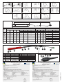
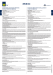
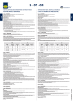
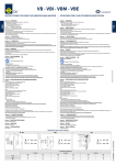
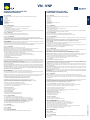
ISTRUZIONI PER L’USO DEL VIBRATORE AD IMMERSIONE Section 0 – DESCRIPTION The VN - VNP immersion vibrators series are designed and constructed in accordance with the following applicable standards: -2006/95/CE -2004/108/CE -2006/42/CE Also in accordance with: - CEI EN 60745-1 The general features are listed below: - Insulation Class F - Protection IP 68 Sezione 0 – DESCRIZIONE I vibratori a immersione serie VN-VNP sono progettati e costruiti secondo le direttive: -2006/95/CE -2004/108/CE -2006/42/CE E secondo la norma : - CEI EN 60745-1 Le caratteristiche generali sono di seguito elencate: - Classe isolamento F - Protezione IP 68 Section 1 – GENERAL REGULATIONS Read these instructions carefully before using the product, and keep the Manual safe for future reference. On receiving the product check: - To make sure the packing is not damaged to such an extent as to have damaged the product. - To make sure there is no external damage to the product. - To make sure the supply corresponds to the order specifications; non compliance and/or external damage, if any, must be reported immediately in detail to the forwarding agent and the manufacturer and/or dealer. Sezione 1 – NORME GENERALI Leggete attentamente queste istruzioni prima di utilizzare il prodotto, e custodite questo manuale per futuri riferimenti. Al ricevimento del prodotto controllate che: - L’imballo non risulti deteriorato al punto di aver danneggiato il prodotto. - Non vi siano danni esterni al prodotto. - La fornitura corrisponda alle specifiche dell’ordine; eventuali non conformità e/o danni esterni riscontrati dovranno essere segnalati immediatamente in modo dettagliato sia allo spedizioniere che alla casa produttrice e/o rivenditore. Section 1.1 – IDENTIFICATION The CM converter’s type and other various data are embossed on the identification plate. This information must always be stated when requesting spare parts or a technical intervention. Sezione 1.1 – IDENTIFICAZIONE Il modello dell’ago vibrante e altri dati sono stampigliati sull’apposita targhetta di identificazione. Questi dati devono essere sempre citati per eventuali richieste di parti di ricambio e per interventi di assistenza. Section 1.2 – USE OF THE VIBRATOR The VN - VNP immersion vibrators can only be used for compacting cement, in strict compliance with the Manufacturer’s Operation Manual. Its use for jobs different from those envisioned and non-conform to that described in this booklet, as well as being considered improper and prohibited, releases the Manufacturer from any direct and/or indirect liability. Sezione 1.2 – DESTINAZIONE D’USO Il vibratori ad immersione serie VN - VNP possono essere utilizzati solo per la compattazione del cemento ed in stretta osservanza del manuale di funzionamento del produttore. L’utilizzo dello stesso per impieghi diversi da quelli previsti e non conformi a quanto descritto in questo opuscolo, oltre ad essere considerato improprio e vietato, scarica la Ditta Costruttrice da qualsiasi responsabilità diretta e/o indiretta. Section 2 – GUARANTEE The Manufacturer provides a 24 (twenty-four)-months guarantee on all the products valid from the date of purchase (as indicated in the goods transport document). The guarantee covers all the mechanical parts except those subject to wear. The guarantee becomes invalid, together with all direct and indirect responsibility, if the product has been tampered with or used improperly, and if the spare parts used are not genuine. The materials returned for repair within the guarantee period are CARRIAGE PAID. Section 3 – SAFETY STANDARDS Operators: Only qualified, trained operators must be allowed to use the machine. Minors qualified for carrying out work can only do so with permission and under the supervision of the person in charge of operations. Noise level: The weighted equivalent continuous noise pressure of the equipment NEVER exceeds 90 dB(A)* * Measurements made in normal operating conditions in accordance with UNI EN ISO11202, with simulated load. BEFORE USE: Before starting work, check the machine and the relative safety devices to make sure they are intact and in perfect working order. Damaged or worn parts, if any, must be replaced or repaired by specialist, authorized persons. - Make sure the power supply voltage and amperages correspond to the indications on the data plate (Fig.1). - Disconnect the plug when the machine is not being used, and before carrying our maintenance, cleaning or repairs. - Follow the indications and the hazard signs present on the machine. - Wear appropriate P.P.E. DO NOT TAMPER WITH OR REMOVE THE SAFETY DEVICES CORRECT USE OF THE CABLE: Never drag the machine by pulling at the cable, never tug at the cable to disconnect the plug; never knot or twist the cable. Do not immerse or take the vibrator out by holding it by the cable. Keep the cable away from heat sources, oils and sharp objects. Do no switch the machine on/off by inserting or disconnecting the plug; use the switch. (Fig.2) EXTENSIONS: The extension cable (if present) must be complete with plug/socket with earth connection in compliance with the standards in force. For 250V machines, use extension cables suitable for outdoor use and duly marked for the purpose. Check to ensure the suitability of the extension cable cross-section in relation to its length. POSITIONING OFF THE GROUND: If working on scaffolding or other areas above the ground, make sure the machine is not left unsupervised when switched on, and that it rests stably when it is not in operation, to prevent harm to persons and damage to objects below it, because of vibration and imbalance. CARE OF THE MACHINE: Keep the machine clean and in good condition to obtain the best results. Follow the indications given in the Maintenance section. Check the cable periodically and have it replaced by specialist, authorized personnel if damaged. IN ADDITION TO THE ABOVE, COMPLY WITH THE STANDARDS IN FORCE IN THE COUNTRY WHERE THE MACHINE IS USED. Section 4 – OPERATIVE NOTES USE: The immersion vibrator is used for compacting concrete by immersion of the vibrating needle (Fig. 3). Correct working of the machine is ensured only if it is used in compliance with the instructions given in this Manual, which must be read carefully and preserved. The converter amperage A must be 0 or > than the total A absorbed by the vibrators powered by it. WORKING: Check to make sure the mains voltage is equal to that indicated on the plate. Insert the plug in the electric panel, and switch on the machine using the buttons on the switch. At the end of the job, switch off the machine by pressing O on the switch. Disconnect the plug from the panel. Work with the vibrating needle completely immersed in the concrete, to prevent it getting overheated. DO NOT IMMERSE THE CONVERTER, THE CABLE, THE DIFFERENTIAL AND THE PLUG IN THE CONCRETE. If the THERMAL CUT-OUT SWITCH is activated following overheating of the vibrating needle because of incorrect use: - Switch the machine off and immerse the vibrating needle in cold water for a few minutes, to accelerate the cooling (Fig.4). - Resume the operation making sure the vibrating needle is immersed completely in the concrete (Fig. 3) If the thermal cut-out is activated again after the above-mentioned operation: - Check to make sure the needle is completely immersed in the concrete as it works. - Check to make sure it has been cooled properly; otherwise, repeat the operation described above correctly. If the problem persists, contact the manufacturer or the dealer. Sezione 2 – GARANZIA Il costruttore garantisce i propri prodotti 24 (ventiquattro) mesi dalla data di acquisto (fa fede il documento di trasporto della merce). La garanzia copre tutte le parti meccaniche ed esclude quelle soggette ad usura. La garanzia decade, e con essa ogni responsabilità diretta o indiretta, qualora il prodotto sia stato manomesso o utilizzato in modo improprio, siano state fatte riparazioni o modifiche da personale non autorizzato, siano stati utilizzati ricambi non originali. I materiali resi per riparazione in garanzia vanno resi in PORTO FRANCO. Sezione 3 – NORME DI SICUREZZA Operatori: Solo operatori qualificati e formati possono utilizzare la macchina. Minorenni abilitati a svolgere attività lavorativa posso operare solo dopo previa autorizzazione e sorveglianza da parte del responsabile del luogo di lavoro. Rumorosità: Il livello di pressione acustica continua equivalente ponderata degli apparecchi NON è mai superiore ai 90 dB(A)* *Rilevazione effettuata in condizioni di normale funzionamento secondo la norma UNI EN ISO11202, con carico simulato. PRIMA DELL’UTILIZZO: Prima di iniziare il lavoro controllate la perfetta integrità della macchina e dei relativi dispositivi di sicurezza, così come il regolare funzionamento della stessa. Eventuali parti danneggiate o usurate dovranno essere sostituite o riparate da personale specializzato e autorizzato. - Accertarsi che la tensione di alimentazione e gli amperaggi corrispondano a quanto indicato sulla targhetta(fig.1). - Disinserire la spina quando non utilizzate la macchina, prima di eseguire operazioni di manutenzione, pulizia, riparazione. - Attenetevi alle indicazioni ed ai segnali di pericolo riportati sulla macchina. - Indossate i D.P.I idonei. E’ VIETATO MANOMETTERE O TOGLIERE I DISPOSITIVI DI SICUREZZA. USO CORRETTO DEL CAVO: Non trascinate la macchina tirandola per il cavo; non strattonate il cavo per estrarre la spina; non annodate o attorcigliate il cavo. Non immergete ed estraete il vibratore tenendolo per il cavo. Tenete il cavo lontano da fonti di calore, oli o oggetti taglienti. Non accendete e spegnete la macchina inserendo ed estraendo la spina ma utilizzate l’interruttore. (fig.2) PROLUNGHE: l’eventuale cavo di prolunga deve essere competo di spina/presa e con messa a terra conforme alle normative in vigore. Per la macchina a 250V utilizzate cavi di prolunga adatti per l’impiego esterno e contrassegnati per tale uso. Verificare l’idoneità della sezione del cavo di prolunga usato in rapporto alla sua lunghezza. UBICAZIONE RIALZATE DA TERRA: Lavorando su impalcature o altre zone rialzate da terra, assicuratevi che la macchina non venga lasciata incustodita quando è accesa, e che poggi stabilmente quando non è in funzione, per evitare che, per effetto della vibrazione o di sbilanciamento, questa cada provocando danni a cose e persone sottostanti. CURA DELLA MACCHINA:Mantenere la macchina in buone condizione e pulita per ottenere migliori risultati. Seguite le istruzioni indicate nella sezione di manutenzione. Controllate periodicamente il cavo e se fosse danneggiato fatelo sostituire da personale specializzato e autorizzato. OLTRE A QUANTO SOPRA INDICATO DEVONO ESSERE RIPSETTATE LE NORME IN VIGORE NEL PAESE IN CUI SI OPERA. Sezione 4 – NOTE OPERATIVE UTILIZZO: Il vibratore a immersione è utilizzato per la compattazione del calcestruzzo, mediante l’immersione dell’ago vibrante (fig.3). Il corretto funzionamento della macchina viene garantito solo se questa viene utilizzata conformemente alle istruzioni indicate nel presente manuale, che deve essere consultato attentamente e conservato. Gli A (Ampere) del convertitore devono essere 0 o > al totale degli A assorbiti dai vibratori alimentati dallo stesso. COME OPERARE. Controllate che la tensione della rete sia uguale a quanto indicato sulla targhetta. Inserire la spina nel quadro elettrico, accendere la macchina con il tasti I sull’interruttore. A fine lavoro spegnete la macchina con il tasto O sull’interruttore. Staccate la spina dal quadro. Lavorate con l’ago vibrante completamente immerso nel calcestruzzo, per evitare il surriscaldamento dello stesso. NON IMMERGETE IL CONVERTITORE, IL CAVO, IL DIFFERENZIALE E LA SPINA NEL CALCESTRUZZO. In caso di INTEVENTO DELLA TERMICA, a seguito di surriscaldamento dell’ago vibrante per uso non corretto: - Spegnere la macchina e immergere l’ago vibrante in acqua fredda per qualche minuto, per accelerarne il raffreddamento (fig.4). - Riprendete il lavoro assicurandovi che l’ago vibrante sia completamente immerso nel calcestruzzo (fig. 3) FOR BEST RESULTS FROM THE ARTICLE: - Position the vibrator vertically on the concrete - Lower the vibrator rapidly (Fig. 5 and 5b). - Remove the vibrator slowly (Fig. 6) Se la termica dovesse intervenire nuovamente dopo detta operazione: - Verificate se l’ago lavora completamente immerso nel calcestruzzo. - Verificate se il raffreddamento è stato fatto correttamente e in caso contrario ripetere correttamente quanto scritto sopra. Se il problema persiste contattare il produttore o il rivenditore di zona. FOR CASTING IN LOW FORMWORKS: - Immerse the needle horizontally at the beginning of the formwork. - Gently pull the vibrator along the length of the formwork (Fig. 7). PER UN MIGLIORE RISULTATO DEL MANUFATTO: - Posizionate il vibratore verticalmente sul calcestruzzo - Calate il vibratore rapidamente (fig. 5 e 5b). - Estraete il vibratore lentamente (fig. 6). Section 4.1 – INCORRECT OPERATIONS - Do not use the vibrator like a shovel for spreading the concrete (Fig.8). - Avoid leaving the vibrator switched on for long periods when it is not immersed in the concrete (Fig.9). - Do not immerse the converter, the cable, the differential and the plug in the concrete or other liquids (Fig.10). - Do not immerse and do not vibrate with the vibrator in direct contact with the walls of the formwork (Ffig.11). - Do not jam or do not insert the needle in the reinforcement inside the cast (Fig.12). - Do not switch the vibrator off when it is immersed in the concrete, as it may be difficult to get it out (Fig.13) - Do not lower the vibrator into or lift it out of the concrete by its cable or by tugging at it (Ffig.14). - Do not hold the vibrating needle in the hand while it is in operation (Fig.15) Section 5 – MAINTENANCE The machine does not require maintenance Section 6 – SPARE PARTS Please refer to table (tab.A) Section 7 – PROBLEMS AND BREAKDOWNS in case of breakdown, interupt the work and contact a qualified repairer or OLI staff for a technical check. ITA INSTRUCTIONS FOR USING THE IMMERSION VIBRATOR PER GETTARE IN CASSEFORME BASSE: - Immergete l’ago orizzontalmente a inizio cassero. - Tirate lentamente il vibratore per la lunghezza del cassero (Fig. 7). Sezione 4.1 – OPERAZIONI ERRATE: - Non usate il vibratore come pala per distribuire il calcestruzzo (fig.8). - Evitare di tenere il vibratore a lungo acceso quando non è immerso nel calcestruzzo (fig.9). - Non immergete il convertitore, il cavo, il differenziale e la spina nel calcestruzzo o altri liquidi (fig.10). - Non immergete e non vibrate con il vibratore a diretto contatto delle pareti del cassero (fig.11). - Non incastrate e non infilate l’ago nell’armatura interna alla gettata (fig.12). - Non spegnete il vibratore quando è immerso nel calcestruzzo, per evitare che lo stesso non possa più essere recuperato (fig.13) - Non calate o estraete il vibratore dal calcestruzzo tenendolo o tirandolo per il cavo (fig.14). - Non tenete in mano l’ago vibrante quando è in funzione (fig.15) Sezione 5 – MANUTENZIONE La macchina non richiede manutenzione. Sezione 6 – RICAMBI Fare riferimento alla tabella (tab.A) Sezione 7 – GUASTI E ANOMALIE Se riscontrate anomalie nel funzionamento dell’ago vibrante, sospendete il lavoro e fate controllare la macchina da personale specializzato o dall’assistenza OLI. CODE: OLVNITEN02 | DATE: 11/2010 ENG VN - VNP TECNICHAL DATA / DATI TECNICI D C B A Mechanical and Electrical features MODEL Fc Weight HAND/HARM VIBRATION A B Kg m/s2 mm 9,2 < 2,5 360 13,6 <4 460 15,2 380 13,4 V Hz A Rpm kg VN 36 42 200 6 12000 135 VN 50 42 200 8 12000 300 VN 60 42 200 12 12000 VNP 50 42 200 15 12000 VNP 57 VNP 65 42 200 42 18 200 21 12000 575 12000 Dimensional Features 15,2 740 C D m m 5 10 365 5 10 50 <4 375 5 10 60 <4 400 5 10 50 <4 19,6 Cable cross-section in case of cable extension 443 <4 5 422 10 5 Max cable leght cable cross section mm m mm2 36 30 2,5 20 2,5 30 4 20 4 30 6 20 4 30 6 20 6 30 10 20 6 30 10 57 10 65 VN VNP SPARE PARTS / RICAMBI POS. 1 2 2A � 2A 3 DESCRIPTION VIBRATING NEEDLE TOP VULCANIZED TOP CABLE GLANDE KIT FOR VIBRATING NEEDLE 4 ABS SWITCH BOX AN COVER 5 6 LEAD SWITCH GASKET DESCRIZIONE AGO PUNTALE PUNTALE VULCANIZZATO KIT PRESSACAVO AGO VIBRANTE SCATOLA INTERRUTTORE IN ABS CON COPERCHIO MANICOTTO GUARNIZIONE INTERRUTTORE POS. 7 8 9 10 11 12 13 14 15 DESCRIPTION CONTROL HOSE SWITCH SWITCH SUPPORT LEAD CLAMP CONTROL HOSE CLAMP PLUG 42v 200Hz 3P INTERNAL WIRE CONTROL HOSE CLAMP COMPLETE SWITCH BOX DESCRIZIONE TUBO DI MANOVRA INTERRUTTORE SUPPORTO INTERRUTTORE FASCETTA MANICOTTO FASCETTE TUBO DI MANOVRA SPINA 42v 200Hz 3P CAVO SPIRALATO FASCETTA TUBO DI MANOVRA SCATOLA INTERR. IN ABS COMPLETA OLI SpA Via Canalazzo, 35 - 41036 Medolla (MO) - ITALY e-mail: [email protected] - www.olivibra.com � �� � �� � �� OLI SpA Via Canalazzo, 35 - 41036 Medolla (MO) - ITALY e-mail: [email protected] - www.olivibra.com DICHIARAZIONE DI CONFORMITA’ DECLARATION OF CONFORMITY With the directives of the European Union The VN - VNP poker series are designed and constructed in accordance with the following directives: - 2006/95/CE - 2004/108/CE - 2006/42/CE The conformity has been verified according to the conditions included in the following standard documents: · CEI EN 60745-1 Alle Direttive Della Comunità Europea I vibratori ad immersione serie VN - VNP sono progettati e costruiti secondo le direttive vigenti: - 2006/95/CE - 2004/108/CE - 2006/42/CE DECLARATION OF CONFORMITY: “B” Type: »» These products,VN - VNP series are manufactured according to 2006/42/CE and subsequent amendments. »» These products must not be put into service until the final machinery into which it is to be incorporated has been declared in conformity with the provisions of this Directive, where appropriate. DICHIARAZIONE DI CONFORMITA’: “B” Type: »» Questi prodotti serie VN - VNP sono costruiti in accordo con la direttiva 2006/42/CE e successivi emendamenti. »» Questi prodotti non devono essere messi in servizio finchè la macchina finale, in cui devono essere incorporati, non è stata dichiarata conforme, se del caso, alle disposizioni della presente Direttiva. 1.1.1. - Definitions 1.1.2. - Principles of safety integration 1.1.3. - Materials and products 1.1.5. - Design of machinery to facilitate its handling 1.2.3. - Starting 1.2.4. - Stopping 1.2.4.1. - Normal Stop 1.3.1. - Risks of loss of stability 1.3.2. - Risks of break-up during operation 1.3.4. - Risks due to surfaces, edges or angles 1.1.1. - Definizioni 1.1.2. - Principi di integrazione della sicurezza 1.1.3. - Materiali e prodotti 1.1.5. - Progettazione della macchina ai fini della movimentazione 1.2.3. - Avviamento 1.2.4. - Arresto 1.2.4.1. - Arresto operativo 1.3.1. - Rischio di perdita di stabilità 1.3.2. - Rischio di rottura durante il funzionamento 1.3.4. - Rischi dovuti a superfici, spigoli ed angoli La conformità è stata verificata sulla base dei requisiti delle norme o dei documenti normativi riportati di seguito: · CEI EN 60745-1 According to Annex II B of Directive 2006/42/EC machines, the following essential requirements of safety and health protection are applied and respected: 1.3.7. - Risks related to moving parts 1.3.8. - Choice of protection against risks arising from moving parts 1.4.1. - General requirements 1.5.1. - Electricity supply 1.5.2. - Static electricity 1.5.4. - Errors of fitting 1.5.8. - Noise 1.5.9. - Vibration 1.6.1. - Maintenance on the machine 1.6.4. - Operator’s intervention 1.7.1. - Information and warnings on the machine 1.7.2. - Warning of residual risks 1.7.3. - Marking of machinery 1.7.4. - Instruction 1.7.4.1. - General principles for the drafting of instructions 1.7.4.2. - Contents of the instructions 1.7.4.3. - Sales literature 2.2.1. - General consideration 2.2.1.1. - Instructions OLI SpA undertakes to transmit, in response to a reasoned request by the national authorities, relevant information on the products on the present declaration, except for intellectual properties of the producer. The information will be transmitted directly to the national authority, as requested. Person authorised to compile the technical documentation: Giorgio Gavioli OLI S.p.A. Via Canalazzo, 35 – 41036 Medolla (MO) Italy Medolla 02/05/2010 Signature Giorgio Gavioli (General Manager) Ai sensi dell’allegato II B della direttiva Macchine 2006/42/CE sono applicati e rispettati i seguenti requisiti essenziali di sicurezza e di tutela della salute. 1.3.7. - Rischi dovuti agli elementi mobili 1.3.8. - Scelta di una protezione contro i rischi dovuti agli elementi mobili 1.4.1. - Requisiti generali 1.5.1. - Energia Elettrica 1.5.2. - Elettricità statica 1.5.4. - Errori di montaggio 1.5.8. - Rumore 1.5.9. - Vibrazioni 1.6.1. - Manutenzione della macchina 1.6.4. - Intervento dell’operatore 1.7.1. - Informazioni e avvertenze sulla macchina 1.7.2. - Avvertenze in merito ai rischi residui 1.7.3. - Marcatura delle macchine 1.7.4. - Istruzioni 1.7.4.1. - Principi generali di redazione 1.7.4.2. - Contenuto delle istruzioni 1.7.4.3. - Pubblicazioni illustrative o promozionali 2.2.1. - Considerazioni generali 2.2.1.1. - Istruzioni OLI S.p.A si impegna a trasmettere, in risposta a una richiesta adeguatamente motivata delle autorità nazionali, informazioni pertinenti sui prodotti oggetto della presente dichiarazione, fatti salvi i diritti di proprietà intellettuale del fabbricante. Le informazioni verranno trasmesse direttamente all’autorità nazionale che le ha richieste. La persona autorizzata a costituire la documentazione tecnica: Giorgio Gavioli OLI S.p.A. Via Canalazzo, 35 – 41036 Medolla (MO) Italy Medolla 02/05/2010 Firma Giorgio Gavioli (il Legale Rappresentante) CODE: OLVNITEN02 | DATE: 11/2010 � � � � �