1
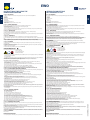
GEBRAUCHSANLEITUNG
DES INNENRÜTTLERS
Section 0 – DESCRIPTION
Teil 0 – BESCHREIBUNG
Section 1 – GENERAL REGULATIONS
Teil 1 - ALLGEMEINE NORMEN
Section 1.1 – IDENTIFICATION
Teil 1.1 – IDENTIFIKATION
Section 1.2 – INTENDED USE
Teil 1.2 - GEBRAUCHSBESTIMMUNG
The EWO series of immersion electronic vibrators are designed and constructed in accordance with the following Directives:
- 2006/95/EC
- 2004/108/EC
- 2006/42/EC
And in accordance with standard:
- CEI EN 60745-1
- CEI EN 60745-2-12
The general features are listed below.
- Insulation Class F
- IP68 protection for vibrating needle and for electronic converter.
Read these instructions carefully before using the product, and keep the Manual safe for future reference.
On receiving the product check:
- To make sure the packing is not damaged to such an extent as to have damaged the product.
- To make sure there is no external damage to the product.
- To make sure the supply corresponds to the order specifications; non compliance and/or external damage, if any, must be reported immediately in
detail to the forwarding agent and the manufacturer and/or dealer.
The electrical data and product identification codes are shown on the rating plates (converter Fig.1 - vibrating needle Fig.2).
This data must always be stated when for ordering spare parts or requesting assistance.
Before using the machine indicate the identification data on the identification Table on the page at the back of this Manual, so that the serial number
can be traced rapidly.
The EWO immersion vibrators must only be used for consolidating fresh concrete in strict compliance with the Operation Manual.
For correct working of the equipment it is necessary to abide by the instructions given in the Manual which must obviously be consulted before starting
work.
Using the equipment for purposes other than those envisaged and not conforming to what is described in this Manual will not only be
considered as forbidden and improper, but will also free the Manufacturer of all direct and/or indirect responsibility.
Section 2 – GUARANTEE
The Manufacturer provides a 24 (twenty-four)-months guarantee on all the products valid from the date of purchase (as indicated in the goods
transport document).
The guarantee excludes all parts subject to wear.
The guarantee becomes invalid, and together with it all direct and indirect responsibility, if the product has been tampered with or used improperly,
and if the spare parts used are not genuine.
The materials returned for repair within the guarantee period are CARRIAGE PAID.
Section 3 – SAFETY STANDARDS !
SAFETY INDICATIONS
Follow the indications and the hazard signs present on the machine.
ūū Attention: shock hazard
ūū Do not open the appliance body
ūū Read the Operator’s Manual
OPERATOR SAFETY
•The equipment must be used solely by qualified trained operators. Unqualified personnel can use the equipment provided they are authorized by the
site Manager and under his supervision.
•Wear appropriate P.P.E.
•The site Manager must make sure the operator has read and understood the User Manual which must be kept safe at the workplace. If the Manual is
lost, contact OLI for a copy or download it from our website www.olivibra.com
ATTENTION: The board remains powered as long as the plug is connected to the main power distribution board.
FUNCTIONAL SAFETY OF THE VIBRATOR
•When the work cycle ends, or before carrying out maintenance, cleaning or shifting at the site, set the equipment in safety condition by
disconnecting the plug.
•Avoid contact with the bottle during the working or immediately afterwards to prevent accidental burns.
•Place the electronic converter gently on the ground and handle the switchbox with care to avoid accidental breakage due to mechanical impact.
•Keep the converter safe, protected from impact.
•Noise level: The weighted equivalent continuous noise pressure of the equipment NEVER exceeds 90 dB(A)*
* Measurements made in normal operating conditions in accordance with UNI EN ISO 11202, with simulated load.
IN ADDITION TO THE ABOVE, COMPLY WITH THE STANDARDS IN FORCE IN THE COUNTRY WHERE THE MACHINE IS USED.
Section 4 – SETTING IN SERVICE AND USING THE VIBRATOR
•Before starting work, check the machine and the relative safety devices to make sure they are intact and in perfect working order. Damaged or worn
parts, if any, must be replaced or repaired by specialist, authorized persons.
•Make sure the power supply voltage and amperages correspond to the indications on the data plate
•Incorrect voltage can damage the equipment.
CONNECTION TO GENERATORS WILL INVALIDATE THE GUARANTEE.
•The electricity source must be provided with a ground connection and GFCI differential circuit-breaker.
•In case of overheating, short-circuit, overloads, voltages <180 V o >260 V, the electronic controller board acts by stopping the working of the
equipment.
•Gradual start up prevents critical current peaks during switch off/switch on.
•The extension cables must be complete with plug/socket with earth connection in compliance with the standards in force.
Use H07RN-F cables suitable for outdoors and marked for the purpose. Max. diameters and lengths as per the extensions Table.
OPERATIONAL NOTES
•Insert the plug in the electric panel, and switch on the machine using the buttons on the switch.
•During the work cycle operate the vibrating needle supporting the tube with both hands.
•Immerse the bottle rapidly in the fresh concrete holding it vertical, wait for a few seconds and then remove it slowly
•Keep the vibrating needle immersed in the concrete to prevent overheating
•At the end of the job switch off the equipment by means of button O on the switch and disconnect the plug.
•When the work cycle is complete make sure the switch is always in the "0" position.
To restart the vibrator in case of a block turn the switch to the “0” position, disconnect the plug from the electric panel, rehook and
restore the switch to position “I”.
For use in low formworks:
•Immerse the needle on one side of the formwork and pull it out slowly, holding it horizontal along the entire length of the formwork, towards the
opposite side. (Fig.3).
Die elektronische Innenvibratoren-Serie EWO ist gemäß der folgenden Richtlinien geplant und konstruiert worden:
- 2006/95/EG
- 2004/108/EG
- 2006/42/EG
und gemäß der Normen:
- CEI EN 60745-1
- CEI EN 60745-2-12
Die allgemeinen Eigenschaften sind die Folgenden:
- Isolationsklasse F
- IP-Schutz Vibrationsnadel und Hochfrequenz-Umformer IP 68.
Lesen Sie diese Anweisungen aufmerksam durch, bevor Sie das Produkt benutzen und bewahren Sie das Handbuch auf, um in Zukunft darin nachlesen zu können.
Bei Erhalt des Produkts bitte folgendes prüfen:
- Die Verpackung darf nicht so beschädigt sein, dass das Produkt Schaden genommen hat.
- Das Produkt darf keine sichtbaren Beschädigungen aufweisen.
- Die Lieferspezifikationen müssen den im Auftrag stehenden Spezifikationen entsprechen. Etwaige Fehlmengen bzw. sichtbare Schäden sind sofort sowohl dem
Frachtführer als auch dem Hersteller und/oder Händler detailliert zu melden.
Die elektrischen Daten und die Kennummern des Produkts stehen auf den Typenschildern (Hochfrequenz-Umformer Abb. 1 - Vibriernadel Abb. 2).
Diese Daten sind immer anzugeben, um Ersatzteile zu bestellen oder den Eingriff des Kundendienstes zu verlangen.
Vor Benutzung der Maschine die Kenndaten in die Tabelle mit den Kenndaten auf der Rückseite dieses Handbuchs eintragen, damit man die Serien-Nummer bei
Bedarf schnell finden kann.
Die Innenvibratoren EWO dürfen nur benutzt werden, um frischen Beton so zu verdichten, wie es in der Betriebsanleitung beschrieben wird.
Für den korrekten Betrieb des Geräts ist es erforderlich, die Anweisungen des Handbuchs zu beachten, das natürlich zu lesen ist, bevor man den Arbeitszyklus beginnt.
Die Benutzung des Geräts für Einsätze, die von den in diesem Heft vorgesehenen abweichen oder nicht damit konform sind, ist nicht nur als
bestimmungswidrig und verboten anzusehen, sondern enthebt den Hersteller auch von jeder direkten und/oder indirekten Haftung.
Teil 2 – GARANTIE
Der Hersteller bietet auf seine Produkte eine Garantie von 24 (vierundzwanzig) Monaten ab dem Kaufdatum (es gilt das Datum des Frachtscheins der Ware).
Alle Verschleißteile stehen nicht unter Garantie.
Die Garantie (und damit jede direkte oder indirekte Haftung) verfällt, falls das Produkt manipuliert oder auf bestimmungswidrige Weise benutzt wird, falls Reparaturen oder Änderungen durch unbefugtes Personal ausgeführt wurden oder falls Ersatzteile benutzt wurden, die kein Original sind.
Die Materialien, die in der Garantiezeit zu reparieren sind, müssen FRACHTFREI zugestellt werden.
Teil 3 - SICHERHEITSBESTIMMUNGEN! SICHERHEIT DES BEDIENERS
• Das Gerät darf nur durch qualifiziertes und geschultes Personal benutzt werden. Nicht qualifiziertes Personal darf durch den Baustellenleiter zur Benutzung befugt
werden, falls es unter seiner direkten Überwachung arbeitet.
• Geeignete PSA benutzen.
• Der Baustellenleiter muss sicherstellen, dass der Bediener die Betriebsanleitung gelesen und verstanden hat. Diese ist an der Stelle der Benutzung des Geräts
aufzubewahren. Sollte sie verloren gehen, kann ein neues Exemplar bestellt werden, indem man sich an die Mitareiter bei OLI wendet oder es von der Website
oligmbh.de herunterlädt.
ACHTUNG: Die Steuerkarte bleibt gespeist, solange der Stecker am Hauptschaltkasten angeschlossen ist.
BETRIEBSSICHERHEIT DES VIBRATORS
• Am Ende des Arbeitszyklus oder vor Ausführung von Wartungs- und Reinigungsarbeiten oder dem Transport auf der Baustelle ist das Gerät in einen sicheren
Zustand zu bringen, indem man den Stecker zieht.
• Vermeiden Sie es, die Flasche während des Betriebs oder sofort danach anzufassen, weil Verbrennungsgefahr besteht.
• Den Hochfrequenz-Umformer vorsichtig am Boden abstellen und umsichtig mit dem Schaltergehäuse umgehen, um Beschädigungen infolge mechanischer Stöße zu
vermeiden.
• Den Hochfrequenz-Umformer in sicheren Bedingungen und geschützt vor Stößen halten.
• Lärmpegel: Der gemessene äquivalente Schalldruck (Dauerwert) der Geräte liegt nie über 90 dB(A)*.
*Messung unter normalen Betriebsbedingungen nach der Norm UNI EN ISO11202 mit simulierter Belastung.
NEBEN DEN OBEN STEHENDEN ANGABEN MÜSSEN AUCH DIE NORMEN BEACHTET WERDEN, DIE IN DEM LAND GELTEN, IN DEM MAN ARBEITET.
Teil 4 – INBETRIEBNAHME UND GEBRAUCH DES VIBRATORS
• Bevor man mit der Arbeit beginnt, immer sicherstellen, dass die Maschine und ihre Sicherheitseinrichtungen unversehrt sind und dass die Maschine regelmäßig
funktioniert. Eventuell beschädigte oder verschlissene Teile sind durch spezialisiertes Personal zu reparieren oder auszutauschen.
• Sicherstellen, dass die Speisespannung und die Stromstärke den Angaben auf dem Typenschild entsprechen.
• Eine falsche Speisespannung kann das Gerät beschädigen.
BEI ANSCHLUSS AN NOTSTROMAGGREGATE VERFÄLLT DIE GARANTIE.
• Die Stromquelle, die an das Gerät angeschlossen wird, muss geerdet sein und mit Fehlerstrom-Schutzschalter (GFCI) ausgestattet sein.
• Bei Überhitzung, Kurzschluss, Überlastungen, Spannungen <180 V oder >260 V wird die elektronische Steuerkarte ausgelöst und der Betrieb des Geräts
unterbrochen.
• Der progressive Anlauf verhindert, dass es beim Einschalten und Ausschalten zu kritischen Stromspitzenwerten kommt.
• Die Verlängerungskabel müssen mit Stecker/Steckdose und Erdung gemäß der geltenden Normen versehen sein.
Kabel H07RN-F benutzen, die sich für den Einsatz im Freien eignen und für diesen Einsatz gekennzeichnet sind. Höchstwerte von Durchmesser und Länge gemäß der
Tabelle der Verlängerungskabel.
GEBRAUCHSANWEISUNGEN
• Den Stecker in den Schaltkasten stecken und die Maschine mit der Taste I auf dem Schalter einschalten.
• Während des Arbeitszyklus die Vibrationsnadel betätigen, indem man das Betätigungsrohr mit beiden Händen festhält.
• Die Flasche schnell in den frischen Beton stecken und sie in einer vertikalen Position halten. Ein paar Sekunden abwarten und sie langsam herausziehen.
• Die Vibrationsnadel im Beton eingetaucht halten, um eine Überhitzung zu vermeiden.
• Am Ende der Arbeit die Taste O auf dem Schalter zum Ausschalten benutzen und den Stecker ziehen.
• Am Ende des Arbeitszyklus sicherstellen, dass der Schalter immer in der Stellung "0" steht.
Zum Neustarten des Vibrators nach einer Sperre ist es erforderlich, den Schalter in die Position "0" zu bringen, den Stecker vom Schaltkasten
abzuziehen, ihn wieder einzustecken und den Schalter wieder in die Position "I" zu bringen.
Zur Benutzung in flachen Schalungen:
• Die Nadel auf einer Seite der Schalung eintauchen und langsam über die gesamte Länge der Schalung zur anderen Seite ziehen, wobei sie in einer horizontalen Stellung
bleiben muss. (Abb. 3).
Teil 4.1 - FALSCHE BENUTZUNGSWEISEN:
Section 5 – MAINTENANCE AND CLEANING
Teil 5 – WARTUNG UND REINIGUNG
Before proceeding with the following operations check to make sure the switch is in the “O” position and the plug is disconnected from the electric
panel.
Check the vibrator to make sure it is intact. Take special care with the power cable. If damaged, it must be replaced by specialist authorized personnel.
Breakages if any can cause serious harm to persons due to the presence of electric current.
Clean the converter at the end of each work cycle.
For effective dissipation of the heat accumulated during operation, the converter dissipator must always be kept perfectly clean.
Remove all concrete residue by immersing the bottle in a bed of crushed stone.
Check the switch protection membrane seal.
THE ELECTRONIC CONVERTER DOES NOT REQUIRE ANY MAINTENANCE. OPENING THE CONVERTER BOX WILL INVALIDATE THE GUARANTEE.
Section 6 – SPARE PARTS
Refer to the Table.
Section 7 – TROUBLESHOOTING
Refer to the Table.
In case of operating anomalies of the vibrating needle, stop work and have the machine checked by specialist persons or the OLI assistance service.
!
SICHERHEITSANGABEN
Beachten Sie die Gefahrenangaben und -signale, die auf der Maschine stehen.
ūū Achtung: Stromschlaggefahr!
ūū Den Gehäusedeckel nicht öffnen
ūū Die Betriebsanleitung lesen
Section 4.1 – INCORRECT OPERATIONS:
•Do not pull the machine by the cable.
•Do not pull the cable to disconnect the plug.
•Do not knot or twist the cable.
•Do not immerse or take the vibrator out holding it by the cable.
•Keep the cable away from sources of heat, oil and sharp objects.
•Do not use the vibrator like a shovel for spreading the concrete (Fig.8).
•Avoid leaving the vibrator switched on for long periods when it is not immersed in the concrete.
•Do not immerse the electronic converter, the power cable, switch and plug in the concrete or other liquids.
•Do not immerse and do not vibrate with the vibrator in direct contact with the walls of the formwork (Fig.5).
•Do not jam do not insert the needle in the reinforcement inside the cast (Fig.6).
•Do not switch the vibrator off when it is immersed in the concrete, as it may be difficult to get it out (Fig.7)
•Do not hold the vibrating needle in the hand while it is in operation (Fig.8)
Failure to observe the instructions can cause serious harm to persons.
DE
INSTRUCTIONS FOR USING THE
IMMERSION VIBRATOR
• Die Maschine nicht transportieren, indem man am Kabel zieht.
• Nicht am Kabel ziehen, um den Stecker herauszuziehen.
• Keine Knoten oder Schlingen im Kabel entstehen lassen.
• Zum Eintauchen oder Herausziehen des Vibrators darf man ihn nicht am Kabel halten.
• Das Kabel entfernt von Hitzequellen, Öl oder schneidenden Gegenständen halten.
• Den Vibrator nicht zum Verteilen des Betons benutzen (Abb. 4).
• Vermeiden Sie es, den Vibrator lange eingeschaltet zu halten, wenn er sich nicht im Beton befindet.
• Den Hochfrequenz-Umformer, das Speisekabel, den Schalter und den Stecker nicht in den Beton oder andere Flüssigkeiten halten.
• Den Vibrator nicht so eintauchen und in Vibration bringen, dass er direkten Kontakt mit den Schalungswänden hat (Abb. 5).
• Die Vibrationsnadel darf nicht in die Bewehrung im Beton eingeführt und eingesteckt werden (Abb.6).
• Den Vibrator nicht ausschalten, wenn er in den Beton eingetaucht ist, um zu vermeiden, dass man ihn nicht mehr herausziehen kann (Abb. 7).
• Die Vibrationsnadel nicht in der Hand halten, wenn sie in Funktion ist (Abb. 8)
Die Nichtbeachtung dieser Vorschrift kann zu schweren Personenschäden führen.
Vor der Ausführung der folgenden Vorgänge sicherstellen, dass sich der Schalter in der Position “O” befindet und der Stecker nicht am Schaltkasten angeschlossen ist.
Den Vibrator einer Sichtprüfung unterziehen, um festzustellen, dass er unversehrt ist. Besonders auf das Speisekabel achten. Sollte es beschädigt sein, muss es durch
befugtes und spezialisiertes Personal ersetzt werden.
Etwaige Beschädigungen können zu schweren Personenschäden führen, die auf dem Vorhandensein von Strom beruhen.
Den Hochfrequenz-Umformer am Ende jedes Arbeitszyklus reinigen.
Für eine wirksame Ableitung der während des Betriebs angesammelten Hitze ist es unbedingt erforderlich, dass der Kühlkörper des HochfrequenzUmformers immer ganz sauber gehalten wird.
Alle Betonreste entfernen, indem man die Flasche in ein Splittbett taucht.
Die Schutzmembran des Schalters auf dichten Sitz prüfen.
DER HOCHFREQUENZ-UMFORMER IST WARTUNGSFREI. DAS ÖFFNEN DES UMFORMERGEHAUSES MACHT DIE GARANTIE UNGÜLTIG.
Teil 6 – ERSATZTEILE
Siehe Tabelle.
Teil 7 – FEHLER UND ANOMALIEN
Siehe Tabelle.
Bei Betriebsstörungen der Vibrationsnadel die Arbeit einstellen und die Maschine durch spezialisiertes Personal oder den OLI-Service kontrollieren lassen.
CODE: OLEVOITEN02 | DATE:09/2011
ENG
EWO
PICTURES / ABBILDUNGEN
Pic. / Abb. 3
Pic. / Abb. 5
Pic. / Abb. 4
Pic. / Abb. 6
Pic. / Abb. 7
Pic. / Abb. 8
IDENTIFICATION / IDENTIFIKATION
②
②
①
Via Canalazzo, 35
41036 Medolla (MO)-Italy
www.olivibra.it
①
Mod.
IDENTIFICATION CHART / IDENTIFIKATIONSTABELLE
Year/SN
PRI
Hz
Rpm
POS.
DESCRIPTION /
BESCHREIBUNG
1
MOD.
2
MATR. / YEAR
Made in ITALY
A
KVA
IP
Kg
SIMBOLI VEDI COPIA ALLEGATA
Pic. / Abb. 2
Pic. / Abb. 1
DATA / DATEN
TECHNICAL DATA / TECHNISCHE DATEN
B
C
A
E
D
Mechanical and electrical features / Mechanische und elektrische Eigenschaften
Electronic Converter / Hochfrequenzumformer
TYPE / TYP
Dimensional Features / Platzbedarf
EXTENSION CABLE CHART / TABELLE DER VERLÄNGERUNGSKABEL
Vibrating needle / Vibriernadel
Input
Input
Output
Output
Max Output
voltage
frequency
voltage
frequency
current
V
Hz
V
Hz
A
Fc
Vibration /
Vibration
Amperage /
Stromstärke
Kg
Vpm
Input
Total
Power
Weight
Hand-Arm Vibration / Vibrationen
Hand/Arm
A
B
C
D
ØE
A
Kw
Kg
m/s2
mm
m
m
m
mm
EWO 36
135
3
1,1
12
< 2.5
360
5
10,2
2,2
36
EWO 50
300
3,8
1,2
17
<4
365
5
10,2
2,2
50
4,5
1,4
18
<4
375
5
10,2
2,2
60
EWO 60
EWO 50P
180 ÷ 260
1ph
50/60
230
3ph
200
5,5
460
380
12000
5
1,6
16
<4
400
5
10,2
2,2
50
EWO 57P
575
6
1,9
18
<4
443
5
10,2
2,2
57
EWO 65P
740
7,5
2,4
22
<4
422
5
10,2
2,2
65
Cable cross-section in case of cable extension / Kabelquerschnitt bei Verlängerungskabeln
Max leght / Max. Länge
Cable cross section / Kabelquerschnitt
m
mm2
20 ÷ 30
2,5
20 ÷ 30
4
20
6
30
6
SPARE PARTS / ERSATZTEILE
�
�
�
�
� �
�
�
�
12A
1
2
2A
3
4
5
6
7
7A
8
DESCRIPTION
DESCRIZIONE
VIBRATING NEEDLE
NADEL
TOP
SPITZE
VULCANIZED TOP
VULKANISIERTE SPITZE
CABLE GLANDE KIT FOR VIBRATING
BAUSATZ KABELVERSCHRAUBUNG VIBRIERNADELE
NEEDLE
ABS SWITCH BOX
ABS SCHALTERGEHÄUSE
LEAD
ANSCHLUSS
SWITCH GASKET
SCHALTERDICHTUNG
CONTROL HOSE
BETÄTIGUNGSSCHLAUCH
CONTROL HOSE PROTECTION
SCHUTZ BETÄTIGUNGSSCHLAUCH
SWITCH
SCHALTER
POS.
DESCRIPTION
DESCRIZIONE
9
SWITCH SUPPORT
SCHALTERTRÄGER
10
LEAD CLAMP
ANSCHLUSSKLEMME
11
CONTROL HOSE CLAMP
BETÄTIGUNGSSCHLAUCHKLEMMEN
11A
CONTROL HOSE CLAMP
BETÄTIGUNGSSCHLAUCHKLEMMEN
12
CONTROL HOSE CLAMP
BETÄTIGUNGSSCHLAUCHKLEMMEN
12A
CONTROL HOSE CLAMP
BETÄTIGUNGSSCHLAUCHKLEMMEN
13
INTERNAL WIRE
SPIRALDRAHT
14
COMPLETE CONVERTER BOX
GEHÄUSE HOCHFREQUENZUMFORMER, KOMPLETT
15
COMPLETE SWITCH BOX
ABS SCHALTERGEHÄUSE, KOMPLETT
TROUBLESHOOTING CHART
Symptom
Symptom
The vibrator does not
start up.
The vibrator is noisy.
Possible
Possible
Cause(s)
Causes
1) Plug not connected correctly.
2) Cable damaged.
3) Voltage different from that indicated on rating
plate.
4) High temperature.
5) Short circuit.
circuit
6) Overload.
1) Bearings need replacement
� �
7A
�
��
11A
� � �
TABELLE DER FEHLERSUCHE
Corrective
Correctiveaction
Action
1) Check the power supply panel.
2) Check the cable.
3) Check the supply voltage.
4) Allow the vibrator enough time to cool down.
5) Contact an authorized OLI centre
6) Check for mechanical obstructions.
To restart the vibrator in case of a block turn the switch to
therestart
To
“0” position,
the vibrator
disconnect
in casethe
ofplug
a block
from
turn
thethe
electric
switchpanel,
to
rehook
the
“0” position,
and restore
disconnect
the switch
thetoplug
position
from“I”.
the electric panel,
rehook and restore the switch to position “I”.
1) Contact an authorized OLI centre
Störung
Der Vibrator läuft nicht an.
Der Vibrator läuft laut.
OLI SpA Via Canalazzo, 35 - 41036 Medolla (MO) - ITALY
e-mail: [email protected] - www.olivibra.com
Mögliche Ursachen
1)Stecker nicht korrekt angeschlossen.
2)Kabel beschädigt.
3)Spannung entspricht nicht dem Wert im
Typenschild.
4)Temperatur zu hoch.
5)Kurzschluss
1)Lager zu ersetzen.
Abhilfe
1)Den Stromanschlusskasten prüfen.
2)Das Kabel prüfen.
3)Die Speisespannung prüfen.
4)Den Vibrator so lange wie erforderlich abkühlen lassen.
5)Wenden Sie sich an eine OLI-Vertragswerkstatt.
Zum Neustarten des Vibrators nach einer Sperre ist es
erforderlich, den Schalter in die Position "0" zu bringen, den
Stecker vom Schaltkasten abzuziehen, ihn wieder einzustecken
und den Schalter wieder in die Position "I" zu bringen.
1)Wenden Sie sich an eine OLI-Vertragswerkstatt.
OLI SpA Via Canalazzo 35 - 41036 Medolla (MO) - IALIEN
E-Mail: [email protected] - www.olivibra.com
DECLARATION OF CONFORMITY
KONFORMITÄTSERKLÄRUNG
With the directives of the European Union
The EWO, EWO-P poker series are designed and constructed in accordance with the following directives:
- 2006/95/CE
- 2004/108/CE
- 2006/42/CE
The conformity has been verified according to the conditions included in the following standard documents:
· CEI EN 60745-1 · CEI EN 60745-2-12
mit den Richtlinien der Europäischen Gemeinschaft
Die Innenvibratoren Serie EWO und EWO-P sind gemäß der geltenden Richtlinien geplant und konstruiert worden:
- 2006/95/EG
- 2004/108/EG
- 2006/42/EG
DECLARATION OF CONFORMITY:
“A” Type:
»» The complete equipment electronic converter - poker vibrator complies with the above standards / guidelines in accordance with Annex II to
Directive 2006/42 EC machines
KONFORMITÄTSERKLÄRUNG:
Typ “A”:
»» Das SYSTEM Hochfrequenz-Umformer + Vibrator entspricht den oben genannten Normen/Richtlinien im Sinne von Anhang II A der MaschinenRichtlinie 2006/42 EG.
OLI SpA undertakes to transmit, in response to a reasoned request by the national authorities, relevant information on the products on the present declaration, except for intellectual properties of
the producer. The information will be transmitted directly to the national authority, as requested.
Firma OLI S.p.A. verpflichtet sich, in Antwort auf eine angemessen begründete Anfrage der nationalen Behörden und vorbehaltlich der Eigentumsrechte des Herstellers passende
Informationen zu den Produkten zu überweisen, die Gegenstand dieser Erklärung sind. Die Informationen werden direkt an die nationale Behörde geschickt, die sie beantragt hat.
Person, die zur Erstellung der technischen Dokumentation befugt ist:
Giorgio Gavioli
Die Konformität wurde aufgrund der Anforderungen der Normen oder der normativen Dokumente geprüft, die hier unten angegeben werden:
· CEI EN 60745-1 · CEI EN 60745-2-12
Person authorised to compile the technical documentation:
Giorgio Gavioli
OLI S.p.A. Via Canalazzo, 35 – 41036 Medolla (MO) Italy
Medolla 18/02/2011
Signature
Giorgio Gavioli
(General Manager)
OLI S.p.A. Via Canalazzo 35 – 41036 Medolla (MO) Italien
Medolla, 18.02.2011
Unterschrift
Giorgio Gavioli
(Rechtlicher Vertreter)
CODE: OLEVOITEN02 | DATE:09/2011
POS.
�
�