1
www.ecoflamburners.com
MODULATING UNIT
EN
IT
FR
ES
RU
RWF 50 - 55
Operating instructions
Istruzioni per l’uso
Notice d’emploi
Manual de uso
Руководство по эксплуатации
Electric diagrams
Schemi elettrico
Schémas électrique
Esquemas eléctrico
Электрические схемы
KITMD-RWF50
KITMD-RWF55
3143713
3143714
EN
IT Index of contents / Indice dei contenuti / Table des matières / Sumario / Содержание
FR
ES
RU Kit modulating unit installation
EN
Montaggio kit modulante
Des kits de montage de modulation
Kits de montaje modular
Монтажные комплекты модуляции
IT
FR
ES
RU
Probe connection
Collegamento sonde
Branchement avec les sondes
Conexion sonda
Подключение датчика
EN
IT
FR
ES
RU
6
Operating instructions for authorised specialists
EN
7 - 16
Istruzione per l’uso per il personale qualificato
IT
17 - 26
Notice d’emploi pour l’installateur spécialiste
FR
27 - 36
Instrucciones de montaje para el instalador especialista
ES
37 - 46
Инструкция по эксплутации для
квалифицированных специалистов
RU
47 - 56
Electric diagrams
Schemi elettrico
Schémas électrique
Esquemas eléctrico
Электрические схемы
EN
IT
FR
ES
RU
57 - 58
Replacement
Sostituzione
Remplacement
Reemplazo
Эамена
EN
IT
FR
ES
RU
59
2
www.ecoflam-burners.com
3,4,5
420010571400
Kit modulating unit installation / Montaggio kit modulante / Des kits de montage de modulation / Kits de montaje modular / Монтажные комплекты модуляции
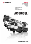
1
2
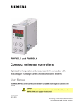
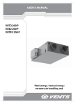
Switch-OFF the burner and remove the
power supply / Spegnere il bruciatore e togliere l’alimentazione elettrica / Arrêter le
brûleur et retirer l'alimentation électrique /
Apagar el quemador y eliminar la fuente
de alimentación/ Выключить горелку и
отсоедините кабель питания.
Remove the cup with a screwdrive / Togliere con un cacciavite il tappo / Enlever
le bouchon avec un tournevis / Quitar el
tapón con un destornillador / С помощью
отвертки снять крышку.
5
4
Look at the connector with jumper / Individuare il conettore con il ponte / Repérer le
connecteur avec le pontet / Identificar el
conector con el puente / Найти разъем с
перемычкой.
3
Open the cover / Aprire il coperchio / Ouvrir le couvercle / Abrir la tapa / Открыть
кожух.
6
RWF 55
6
RWF 50
Remove the jumper / Togliere il ponte /
Enlever le pontet / Quitar el puente /
Снять перемычку.
Fit the gasket / Inserire la guarnizione / Insérer le joint / Introducir la junta /
Установить уплотнительную прокладку.
420010571400
www.ecoflam-burners.com
3
EN
IT
FR
ES
RU
EN
IT Kit modulating unit installation / Montaggio kit modulante / Des kits de montage de modulaFR tion / Kits de montaje modular / Монтажные комплекты модуляции
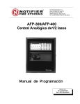
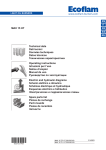
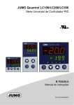
-Remove the clips. -Fit the seal supplied with the controller. -Insert
ES RWF 55
the controller from the front into the panel cutout (1) and make
(3)
certain the seal is correctly fitted.
RU 7
Attention! The controller must be installed with the seal,
preventing water or dirt from entering the housing.
(2)
-Working from the rear side of the panel, push the clips into the
guide slots on the side
of the controller (2) and tighten them evenly using a screwdriver (3)
until the controller housing is seated firmly in the panel cutout.
(1)
(2)
-Rimuovere le staffe di fissaggio. -Inserire la guarnizione in
dotazione sull’alloggiamento dell’apparecchio. -Inserire
l’apparecchio da davanti nell’incasso (1) assicurandosi che la
guarnizione sia posizionata correttamente.
Attenzione! Il regolatore deve essere installato con la
guarnizione in modo da impedire l’ingresso di acqua o olio
all’interno dell’alloggiamento.
-Operando dal lato posteriore del pannello, spingere le staffe di
fissaggio nelle fessure guida sul lato del regolatore (2) e serrare
uniformemente con un cacciavite (3) fino a quando il corpo del
regolatore è inserito completamente nella finestra del pannello.
(3)
-Retirer les crochets de fixation. -Mettre en place sur le corps de l'appareil le joint fourni à la livraison. -Insérer l’appareil par l’avant
dans la découpe de l’armoire de commande (1) et s’assurer que le joint est en position correcte.
Attention! Monter impérativement l'appareil avec son joint, pour éviter la pénétration d'eau ou d'impuretés dans le boîtier!.
-Glisser les crochets de fixation dans les guidages latéraux (2) de l'appareil, à partir de l'arrière de l'armoire de commande, et serrer
simultanément avec un tournevis (3) jusqu'à ce que le boîtier du régulateur soit immobilisé dans la découpe de l'armoire de
commande.
-Extraer las grapas de fijación. - Montar en la carcasa del aparato la junta suministrada. - Insertar el aparato desde delante en la
abertura de cuadro de mando (1), asegurándose de que la junta está correctamente asentada.
Atención! Es imprescindible montar el aparato con la junta, para evitar la penetración de agua o suciedad en la carcasa.
-Desde el lado posterior del cuadro de mando, insertar las grapas de fijación en las guías laterales existentes en el aparato (2) y
apretar uniformemente con un destornillador (3) hasta que la carcasa del regulador quede firmemente asentada en la abertura del
cuadro de mando.
-Снимите крепежные скобы. - Установите уплотнение, входящее в комплект поставки, на корпус устройства. - Вставьте
устройство в вырез панели управления (1) с лицевой стороны, обращая внимание на правильность положения уплотнения.
Внимание! Прибор следует устанавливать вместе с уплотнением, чтобы вода или грязь не могли проникнуть в корпус.
- Сдвиньте крепежные скобы от панели управления в боковые направляющие (2), находящиеся на устройстве, и равномерно
затягивайте их отверткой (3), пока корпус контроллера плотно не сядет в вырез панели управления.
RWF 50
(3)
7
(2)
(1)
4
www.ecoflam-burners.com
(3)
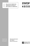
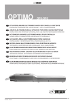
-Remove the frame. -Fit the seal supplied with the controller. -Insert
the controller from the front into the panel cutout (1) and make
certain the seal is correctly fitted.
Attention! The controller must be installed with the seal,
preventing water or dirt from entering the housing.
-Fit the frame from the rear (2) and let it engage in the grooves. Tighten the screws evenly with a screwdriver (3) until the controller
is correctly secured in the panel cutout.
-Rimuovere il telaio. -Inserire la guarnizione in dotazione
sull’alloggiamento dell’apparecchio. -Inserire l’apparecchio da
davanti nell’incasso (1) assicurandosi che la guarnizione sia
posizionata correttamente.
Attenzione! Il regolatore deve essere installato con la
guarnizione in modo da impedire l’ingresso di acqua o olio
all’interno dell’alloggiamento.
-Inserire il telaio spingendolo da dietro (2) e inserirlo incastrandolo il
più possibile nelle scanalature. -Serrare uniformemente le viti del
telaio di fissaggio con un cacciavite (3) fino a che il corpo del
regolatore non sia fissato a filo con l’incasso.
420010571400
Kit modulating unit installation / Montaggio kit modulante / Des kits de montage de modulation / Kits de montaje modular / Монтажные комплекты модуляции
-Retirer le cadre. - Mettre en place sur le corps de l'appareil le joint fourni à la livraison. -Insérer l’appareil par l’avant dans la découpe
de l’armoire de commande (1) et s’assurer que le joint est en position correcte.
Attention! Monter impérativement l'appareil avec son joint, pour éviter la pénétration d'eau ou d'impuretés dans le boîtier!.
-Glisser le cadre par l'arrière (2) et encliquetez-le jusqu'à son maximum sur les rainures du boîtier. - Les vis du cadre de fixation
doivent être serrées uniformément avec un tournevis (3), jusqu'à ce que le boîtier du régulateur soit fixe dans la découpe de l'armoire.
-Retirar el marco. - Montar en la carcasa del aparato la junta suministrada. - Insertar el aparato desde delante en la abertura de cuadro
de mando (1), asegurándose de que la junta está correctamente asentada.
Attention! The controller must be installed with the seal, preventing water or dirt from entering the housing.
- Deslizar el marco desde atrás (2), haciendo que encaje en la mayor medida posible en las ranuras. - Apretar uniformemente con un
destornillador (3) los tornillos del marco de fijación hasta que la carcasa del regulador quede firmemente asentada en la abertura del
cuadro de mando.
-Снимите рамку. - Установите уплотнение, входящее в комплект поставки, на корпус устройства. -Вставьте устройство в вырез
панели управления (1) с лицевой стороны, обращая внимание на правильность положения уплотнения.
Внимание! Прибор следует устанавливать вместе с уплотнением, чтобы вода или грязь не могли проникнуть в
корпус!
-Надвиньте рамку с задней стороны (2), чтобы она вошла в пазы как можно глубже. -Равномерно затягивайте винты рамки
крепления с помощью отвертки (3) до тех пор, пока корпус контроллера не будет плотно сидеть в вырезе панели управления.
9
8
Connect the kit connector in electrical
panel / Collegare il connettore del kit al
pannello elettrico / Brancher le connecteur
du kit au panneau électrique / Conectar el
conector del kit al panel eléctrico /
Присоединить разъем регулятора к
электрическому щитку.
420010571400
Order the cables for closed / Sistemare i
cavi per la chiusura / Ranger les câbles
pour la fermeture / Colocar los cables
para el cierre / Аккуратно уложить
провода.
www.ecoflam-burners.com
5
EN
IT
FR
ES
RU
EN
IT Probe connection / Collegamento sonde / Branchement avec les sondes / Conexion sonda
FR Подключение датчика
ES
WARNING: Before connecting the probe verify that the terminals are not under voltage.
RU
ATTENZIONE: Prima di collegare la sonda verificare che i morsetti non siano in tensione.
!
10
/
ATTENTION: Avant de brancher la sonde pour vérifier que les bornes ne sont pas alimentés.
PRECAUCIÓN: Antes de conectar la sonda para verificar que las terminales no son alimentados.
ВНИМАНИЕ: Перед подключением датчика убедитесь, что терминалы не в напряжении.
TEMPERATURE PROBE (PASSIVE) / SONDE TEMPERATURA (PASSIVA) / SONDE DE TEMPERATURE (PASSIVE) /
SONDA DE TEMPERATURA (PASIVA) / Tемпература датчика (пассивный датчик)
Cod. 3122316
Cod. 3122314
QAE2120.010 (-30+130).
NFT-PT 1000/18.
Electrical connection / Collegamento elettrico / Raccordement électrique / La conexión
eléctrica / Электрическое соединение.
See connection electric diagram probe SP page 57,58 / Vedi schema elettrico collegamento
sonda SP pag. 57,58 / Voir le schéma de connexion sonde SP page.57,58 / Consulte diagrama de conexión de la sonda SP a la página. 57,58 / Смотрите схему подключения
датчика SP стр. 57,58.
Cod. 3122316
11
Cod. 3122314
TEMPERATURE PROBE (ACTIVE) / SONDE TEMPERATURA (ATTIVA) / SONDE DE TEMPERATURE (ACTIF) / SONDA DE
TEMPERATURA (ACTIVO) / Tемпература датчика (активные датчики)
Cod. 3124100
Cod. 3122317
Cod. 3122318
Cod. 3122319
Cod. 3122320
QBE2002-P2 0-2 BAR
QBE2002-P4 0-4 BAR.
QBE2002-P10 0-10 BAR.
QBE2002-P16 0-16 BAR.
QBE2002-P40 0-40 BAR.
Electrical connection / Collegamento elettrico / Raccordement électrique / La conexión
eléctrica / Электрическое соединение.
Cod. 3122317
See connection electric diagram probe SP page 57,58 / Vedi schema elettrico collegamento
sonda SP pag. 57,58 / Voir le schéma de connexion sonde SP page.57,58 / Consulte diagrama de conexión de la sonda SP a la página. 57,58 / Смотрите схему подключения
датчика SP стр. 57,58.
MOUNTING / MONTAGGIO / ASSEMBLEE / MONTAJE / МОНТАЖ
connections
6
www.ecoflam-burners.com
420010571400
EN
RWF 50/55 - Microprocessor regulator - Display
A
RWF 55
RWF 50
B
A
C
D
D
E
E
F
F
P
B
G
G
C
O
N
L
I
M
H
H
M
Enter
ESC
L
RWF50.X
I
A
B
C
D
E
F
G
H
I
L
M
N
O
P
-
Burner release
Controlling element CLOSED
Controlling element OPEN
Operating mode 2-stage
Actual value display (red) and parameter value.
USB-LED
Setpoint display (green) and parameter symbol.
Enter button
Increase value
Decrease value
Esc button
Fonction alarme
Protection contre les chocs thermiques
Communication via l'interface
RWF55.X
Basic display
Enter
Enter
User level OPr
SP1 or SP2 (editabile)
InP1 or (only display)
ESC
Enter
Parameter level
b
7866d12it/0712
OPr
PArA
Heating controller
Cooling controller
>2 s
or timeout
Only RWF50.2:Pb1 dt rt db tt
Navigation principle
Enter
ConF
One level back
One level down
ESC
Enter
Configuration level
ConF
Analog inputs:
InP
Controller:
Cntr
Thermal shock protection
rAFC
Binary inputs:
binF
Display:
diSP
Only RWF50.3
Next/previous parameter
420010571400
Controller outputs:
OutP
www.ecoflam-burners.com
7
EN
RWF 50/55 - Microprocessor regulator - Display
Display diSP
By configuring the position of the decimal point and automatic changeover (timer), both LED indications can be adapted to the respective requirements. Timeout tout for operation and the locking of levels can be configured as well.
SETTING THE DISPLAY
To adjust display proceed as follows :
- Press the Enter button to access the user level OPr,
OPr press the t botton, appare nel display di base ConF.
ConF - Press the Enter button
so that the first parameter of the configuration level is displayed. - Press the t button so that diSP is appears. - Press the Enter button
in display flashes diSP. - Change the value using the keys tand s ,press Enter to confirm.
Parameter
Value/ Selection Description
Display value for upper display
Upper display
diSU
Upper display
0
Switched off
1
Analog input InP1
4
Controller’s angular positioning
6
Setpoint
7
End value with thermal shock protection
Display value for lower display
Lower display
diSL
Lower display
Timeout
tout
Decimal point
dECP
Decimal point
0
Switched off
1
Analog input InP1
4
Controller’s angular positioning
6
Setpoint
7
End value with thermal shock protection
0...
180...
255
0
1
2
Time (s) on completion of which the controller returns automatically to
the basic display, if no button is pressed.
No decimal place
One decimal place
Two decimal places
If the value to be displayed cannot be shown with the programmed
decimal point, the number of decimal places is automatically reduced. If
the measured value drops again, the number of decimal places is
increased until the programmed value is reached
Locking of levels
CodE
8
www.ecoflam-burners.com
0
1
2
3
No locking
Locking of configuration level
Locking of parameter level
Locking of keyboard
420010571400
EN
RWF 50/55 - Microprocessor regulator - Setpoint
When the burner is ignited all displays of the regulator light up. The set point display will blink for about 10 seconds. The value in the
upper field of the display (red) indicates the actual value. The value in the lower field of the display (green) indicates the set point currently programmed.
CHANGING THE SET POINT
To change the set point, proceed as follows :
- Press the Enter button to access the user level OPr,
OPr press the Enter button, SP1 will appear in the lower display. - Press the Enter
button, in display flashes SP1. - Change the value of set point SP1 using the keys tand s ,press Enter to confirm.
WEATHER-COMPENSATED SETPOINT SHIFTING (RWF55)
The RWF55 can be configured so that weather-compensated setpoint shifting is activated when an LG-Ni1000 outside sensor or a
Pt1000 is connected. To take into account the time response of a building, weather-compensated setpoint shifting uses the attenuated
outside temperature rather than the current outside temperature. This attenuated outside temperature is determined on the basis of the
current outside temperature and a filter constant. With the RWF55, this filter value (parameter dF3) can be adjusted. In the event of a
power failure, this filter is reset. The minimum and maximum setpoints can be set using the lower setpoint limit SPL and the upper setpoint limit SPH. The system also prevents the lower working range limit oLLo and upper working range limit oLHi from exceeding/dropping below the system temperature limits.
Heating curve
The heating curve describes the relationship between the boiler temperature setpoint and the outside temperature. It is defined by 2
curve points. For 2 outside temperatures, the user defines the boiler temperature setpoint that is required in each case. The heating
curve for the weather-compensated setpoint is calculated on this basis. The effective boiler temperature setpoint is limited by the upper
setpoint limit SPH and the lower setpoint limit SPL.
Apart from the standard value range limits, there are no other dependencies between the individual curve points.
Setpoint (°C)
H t 1 +60
H t 2 +50
+20
At2
10
0
-10
At1
Temperatura esterna (°C)
SETTING PARAMETERS PAr
PAr A
PID parameters are factory set to standard mean values. The operation of the regulator can be self-adapted to suit the system by activating the tUnE function. The regulator will set the PArA parameters automatically.
To activate the tUnE function proceed as follows:
- With the burner in operation, press t+s buttons for 5 seconds.
- The caption tUnE will blink in the display.
- When tUnE stops blinking, the self-adaptation routine has been completed.
- The parameters calculated by the controller are automatically adopted!
Note!: It is not possible to start tUnE in manual control or low-fire operation.
Self-setting function in high-fire operation
Self-setting function tUnE is a proper software function unit integrated in the controller. In modulating mode, tUnE tests in high-fire
operation the response of the controlled system to angular positioning steps according to a special procedure. A complex control algorithm uses the response of the controlled system (actual value) to calculate and automatically store the control parameters for a PID or
PI controller (set dt = 0!). The tUnE procedure can be repeated any number of times.
Note!: tUnE is only possible in high-fire operation, in modulating burner mode.
2 procedures
The tUnE function uses 2 different methods that are automatically selected depending on the dynamic state of the actual value and
the deviation from the setpoint at startup. tUnE can be started from within any dynamic actual value sequence.
If there is a great difference between actual value and setpoint when tUnE is activated, a switching line is established about which the
controlled variable performs forced oscillations during the self-setting process. The switching line is set to such a
level that the actual value should not exceed the setpoint.
420010571400
www.ecoflam-burners.com
9
EN
RWF 50/55 - Microprocessor regulator - Setting parameters PArA
X
Start
Avvio
With a small deviation between setpoint and actual value (after the controlled system has
Switching
settled, for instance), forced oscillation about the setpoint is performed.
Linea
di
level
commutazione
X
Start
Avvio
The data of the controlled system recorded for the forced oscillations are used to calculate
the controller parameters rt, dt, Pb1 and a filter time constant dF1 for actual
value filtering that is optimized for this controlled system.
regulation reduced
regolazione
ridotta
Conditions
- High-fire operation in modulating burner mode. - The thermostat function (relay K1) must be constantly activated; otherwise tUnE will
be canceled and no optimized controller parameters will be adopted. - The above mentioned actual value oscillations during the selfsetting process must not exceed the upper threshold of the thermostat function (increase if necessary, and lower the setpoint).
Note!
A successfully started Self-setting function is automatically aborted after 2 hours. This could occur in the case of a controlled
system that responds slowly, for example, where, even after 2 hours, the described procedures cannot be successfully
completed.
Checking the controller parameters
Optimum adjustment of the controller to the controlled system can be checked by recording a startup sequence with the control loop
closed. The following diagrams indicate possible incorrect adjustments, and their correction.
Example.:
The response to a setpoint change is shown here for a 3rd order controlled system for a PID controller. The method used for adjusting
the controller parameters can, however, also be applied to other controlled systems. A suitable value for dt is rt/4.
too small
Pb insufficiente
too large
Pb eccessivo
x
x
w
w
7865d17/1099
t
small
r t , dt too
insufficiente
7865d15/1099
too large
r t , dt eccesivo
x
Optimum
adjustment
Impostazione
ottimale
x
x
w
w
w
7865d16/1099
10
t
t
www.ecoflam-burners.com
7865d14/1099
t
7865d18/1099
t
420010571400
EN
RWF 50/55 - Microprocessor regulator - Setting parameters PArA
The PID parameters can be corrected manually from the parameters level, working on the proportional band Pb1, the derivative action time dt and the integral action time rt.
To change parameters Pb1, dt, rt, proceeds as follows: - Press the Enter button to access the parameters level OPr, Press the t
button, appare nel display di base PArA.
PArA - To move from one parameter to the next, press Enter.
Enter - When Pb1 is displayed, the value
can be increased or decreased using the keys tand s (see table), press Enter to confirm. - Press Enter button, to access the next
parameter. - When dt is displayed, repeat the procedure described above. - Press Enter button, to access the next parameter. - When
rt is displayed, repeat the procedure described above. - To return to normal display press ESC.
ESC
DIFFERENTIAL SETTING FOR IGNITION AND SHUTOFF.
The regulator allows the selection of an adjustable switching differential that establishes burner ignition and shutoff values.
HYS1 indicates the lower ignition limit, below which the regulator switches the burner to maximum power. HYS3 indicates
the upper shutoff limit, above which the regulator switches the burner off. To set HYS1 and HYS3 proceed as follows:
- Press the Enter button to access the parameters level PArA.
PArA - To move from one parameter to the next, press Enter.
Enter - When HYS1
is displayed (burner ignition differential-stage II), increase or decrease the value using the t and s keys. - Confirm the changed parameters by pressing Enter button. - Press Enter button, to access the next parameter. - When HYS2 is displayed (burner shutoff differential-stage II), repeat the procedure described above. - Press Enter button, to access the next parameter. - When HYS3 is
displayed (upper shutoff differential) repeat the procedure described above. - To return to normal display press ESC.
ESC
MANUAL/AUTOMATIC MODE
To access “MANUAL” mode, press and hold ESC for at least 5 seconds. Manual mode can only be selected when the burner is in operation. It is deactivated automatically when the burner shuts off. When the HAnd symbol is alight, the regulator is in manual mode and
the position of the servocontrol can be changed using the t and s keys. The LEDS on the front of the regulator indicate whether the
servocontrol OPEN or CLOSE command is currently active. Pressing the s key the servocontrol OPENS. Pressing the t key the servocontrol CLOSES. To select automatic mode press and hold ESC for at least 5 seconds.. The LED above HAnd symbol, goes out
and the regulator reverts to automatic.
RESPONSE THRESHOLD (q)
The response threshold (q) defines for what period of time and how much the actual value is allowed to drop before the system switches to high-fire operation.
An internal mathematical calculation using an integration function determines the sum of all areas qeff = q1 + q2 + q3 as shown in the
graph. This takes place only when the control deviation (x-w) falls below the value of switch-on threshold HYS1. If the actual
value increases, integration is stopped.
If qeff exceeds the preset response threshold (q) (can be adjusted at the parameter level), this causes the second burner stage to
switch on or – in the case of the 3- position controller/modulating controller – the controlling element to open.
If the current boiler temperature reaches the required setpoint, qeff is reset to 0.
Temperature
Temperatura (°C)
q
q
q
7866d09it/0712
q
420010571400
www.ecoflam-burners.com
11
EN
RWF 50/55 - Microprocessor regulator - Setting parameters PArA
Parameter
Display Value range
Factory
setting
Set 50.2/55.2
Ecoflam
(passive probe)
FT-TP/1000
Set 50.2/55.2
Ecoflam
(active probe)
QBE...- P...
10
8
0,1
Proportional band
¹
Pb1
Derivative time
dt
0...9999 s
80
60
50
rt
0...9999 s
350
180
180
1
1
15
15
15
-5
-5
-0,5
3
3
3
5
5
1
0
0
0
Integral action time
Dead band (neutral
zone) ¹
b
db
Controlling element
running time
tt
1...9999 digit
0,0...999,9 digit
10...3000 s
Switch-on threshold
Heating controller ¹
HYS1 1999...0,0 digit
Switch-off threshold
stage II
Heating controller ¹
HYS2
Switch-off threshold
Heating controller ¹
0,0... HYS3 digit
HYS3 0,0...9999 digit
q
Response threshold
0,0...999,9
0,5
Set 55.2 Ecoflam (external probe)
Outside temperature
Curve point1 ¹
At 1
-40......120
- 10
-10
-10
Boiler temperature
Curve point 1 ¹
Ht 1
SPL......SPH
60
68
68
Outside temperature
Curve point 2 ¹
At 2
-40......120
20
22
22
Boiler temperature
Curve point 2 ¹
Ht 2
SPL......SPH
50
48
48
¹ Setting of decimal place has an impact on this parameter.
)
Note! When using the RWF50… as a modulating controller only, or as a modulating controller without the burner
release function (1P, 1N), parameter HYS1 must be set to 0 and parameters HYS2 and HYS3 must be set to their maximum values.
Otherwise, for example, when using default parameter HYS1 (factory setting -5), the 3- position controller is only released
when the control deviation reaches -5 K.
12
www.ecoflam-burners.com
420010571400
EN
RWF 50/55 - Microprocessor regulator - Configuration ConF - Analog input InP1
Basic display
Enter
Enter
User level OPr
SP1 or SP2 (editabile)
InP1 or (only display)
7866d12it/0712
OPr
ESC
Enter
Parameter level
b
Configuration ConF
Here, the settings (e.g. acquisition of measured value
or type of controller) required directly for commissioning
a certain plant are made and, for this reason, there is
no need to change them frequently.
PArA
Heating controller
Cooling controller
>2 s
or timeout
Only RWF50.2:Pb1 dt rt db tt
Navigation principle
Enter
ConF
One level back
One level down
ESC
Enter
Analog input InP1.
Configuration level
ConF
Analog inputs:
InP
Controller:
Cntr
Thermal shock protection
rAFC
Binary inputs:
binF
Display:
diSP
Only RWF50.3
Next/previous parameter
An analog input is available.
Controller outputs:
OutP
Set 50.2/55.2 Set 50.2/55.2
Description
Ecoflam
Ecoflam
FT-TP/1000 QBE.- P.(10bar)
Resistance thermometer Pt100, 3-wire
1
Resistance thermometer Pt100, 2-wire
2
Resistance thermometer Pt1000, 3-wire
3
Resistance thermometer Pt1000, 2-wire
4
4
Resistance thermometer LG-Ni1000, 3-wire
5
Sensor type
Resistance thermometer LG-Ni1000, 2-wire
6
SEn1
0...135 Ohm
7
Sensor type
0...0,20 mA
15
4...0,20 mA
16
0...0,10 V
17
17
0...0,5 V
18
1...0,5 V
19
Correction of
Using the measured value correction (offset), a measured value can be
measured value
corrected to a certain degree, either up or down.
-1999...
OFF1
Example:
1
0
0...
Offset
Measured value (294,7/ 295,3)
+9999
Offset(+0,3/-0,3) Displayed values (295,0/ 295,0)
Caution!: Measured value correction: To make the calculation, the controller uses the corrected value (displayed value). This value
does not represent the value acquired at the point of measurement. If not correctly used, inadmissible values of the control variable
can be produced. Measured value corrections must therefore be made within certain limits only.
Start of display
-1999...
SCL1
In the case of a measuring transducer with standard signal, the
0,0
0...
Scale low level
physical signal is assigned a display value here.
+9999
Example: 0…20 mA = 0…1500 °C
End of display
-1999...
The range of the physical signal can be crossed by 20%, either up or
SCH1
10,0
100...
down, without getting a signal informing about the crossing.
Scale high level
+9999
Parameter
Filter time
constant
dF1
Digital filter
Temperature unit
Unit
Temperature unit
Value/
selection
0.0...
0.6...
100.0...
1
2
0
1
0,0
1
Is used to adapt the digital 2nd order input filter (time in s; 0 s = filter
off). If the input signal changes abruptly, about 26% of the change are
captured after a time corresponding to the filter time constant dF (2 x
dF: approx. 59%; 5 x dF: approx. 96%) When the filter time constant is
great:
- Great attenuation of interference signals
- Slow response of actual value display to changes of the actual value.
- Low limit frequency (low-pass filter)
Degrees Celsius
Degrees Fahrenheit
Unit of temperatures
420010571400
www.ecoflam-burners.com
13
EN
RWF 50/55 - Microprocessor regulator - Configuration ConF - Analog input InP3
Analog input InP3 (RWF55).
This input is used to acquire the outside temperature.
Parameter
Value/
Description
selection
Sensor type
SEn3
Sensor type
0
1
2
Switched-off
Resistance thermometer Pt1000 in 2-wire circuit
Resistance thermometer LG-Ni1000 in 2-wire circuit
Function
FnC3
0
1
No function
Weather-compensated setpoint
Correction of
measured value
OFF3
Offset
Using the measured value correction function (offset), a measured value can
-1999... be corrected by a certain amount, either up or down.
Example: Measurement value(294,7/ 295,3) ,Offset(+0,3/-0,3), Display value (295,0/
0...
+9999 295,0)
Caution! Correction of measured value: To make the calculation, the controller uses the corrected value
(displayed value). This value does not represent the value acquired at the point of measurement. Incorrect use may
lead to impermissible controlled variable values. Only use the measured value correction function within the
permissible limits.
Filter time
Is used to adapt the digital 2nd order input filter (time in s; 0 s = filter off).
constant
dF3
If the input signal changes abruptly, about 26% of the change is captured
Digital filter
0.0... after a time corresponding to the filter time constant dF (2 x dF: approx. 59%;
1278... 5 x dF: approx. 96%).
1500.0... If the filter time constant is large:
- High attenuation of interference signals
- Slow response of actual value display to changes in the actual value.
- Low limit frequency (low-pass filter)
14
www.ecoflam-burners.com
420010571400
EN
RWF 50/55 - Microprocessor regulator - Controller Cntr
Controller Cntr
Here, the type of controller, operating action, setpoint limits and presettings for selfoptimization are selected.
Parameter
Value/
selection
Controller type
CtYP
Controller type
Operating action
CACt
Control direction
Setpoint limitation
start
SPL
Setpoint limitation
low
Setpoint limitation
end
SPH
Setpoint limitation
high
Self-optimization
1
2
1
1
3-position controller (RWF50.2)
Modulating controller (RWF50.3)
0
1
1
1
Cooling controller
Heating controller
-1999...
+9999
0
1
-1999...
+9999
99
10,0
0
1
Lower working
range limit
oLLo
Lower operation
range limit
Upper operation
range limit
oLHi
Upper operation
range limit
Set 50.2/55.2 Set 50.2/55.2
Description
Ecoflam
Ecoflam
FT-TP/1000 QBE.- P.(10bar)
-1999...
+9999
-1999...
+9999
420010571400
Setpoint limitation prevents values from being entered outside the
defined range.
The setpoint limits are not active in the case of predefining
setpoints via the interface. In the case of an external setpoint with
correction, the correction value is limited.
Free
Locked
0
0
Self-optimization can only be disabled or enabled via the ACS411
setup program.
0
90
0
Note!
If the setpoint with the respective hysteresis exceeds the
upper working range limit, the switch-on threshold is
substituted by the working range limit.
9
Note!
If the setpoint with the respective hysteresis drops below
the lower working range limit, the switch-off threshold is
substituted by the working range limit.
www.ecoflam-burners.com
15
EN
RWF 50/55 - Microprocessor regulator - Alarm messages
Display
Cause
Remedy
9999 lampeggia:
Measured value exceeded limit.
The measured value is too great,
lies outside the measuring range,
or the sensor is faulty.
RWF50.X
Check to see if sensor and
connecting line are damaged or
have a short-circuit.
Check to see if the correct sensor is
selected or connected
Measured value dropped below limit.
The measured value is too small,
lies outside the measuring range,
or the sensor has a short-circuit
Check to see if the correct sensor is
selected or connected
USB connection.
Remove USB connection
On the upper display, the decimal
place to the right is lit
16
www.ecoflam-burners.com
420010571400
IT
RWF 50/55 - Regolatore a microprocessore - Display
A
RWF 55
RWF 50
B
A
C
D
D
E
E
F
F
P
B
C
N
L
I
M
H
-
F G -
G
G
O
A
B
C
D
E
H
M
Enter
ESC
L
RWF50.X
I
H
I
L
M
N
O
P
-
Abilitazione bruciatore
Servomotore CHIUSO
Servomotore APERTO
Funzionamento bistadio
Display del valore reale (rosso) e del valore del
parametro.
LED USB
Display del setpoint (verde) e simbolo del
parametro.
Pulsante Enter
Aumentare il valore
Diminuire il valore
Pulsante Esc
Funzione Allarme
Protezione da shock termico
Comunicazione tramite l'interfaccia
RWF55.X
Display di base
Enter
Enter
Livello utente OPr
Modificabile: SP1oppure SP2
Solo indicazione: InPoppure Y
Enter
b
7866d12it/0712
OPr
PArA
>2 s
ESC
oppure Tempo di attesa scaduto
Principio di navigazione
Enter
ConF
Un livello
indietro
Un livello
inferiore
Enter
ESC
Livello configurazione
ConF
Ingressi analogici:
InP
Regolatore:
Cntr
Protezione da shock termico
rAFC
Ingressi binari:
binF
Indicazione:
diSP
Solo RWF50.3
Parametro precedente / successivo
Fi
420010571400
22 P
ti
Uscite di regolazione:
OutP
i
www.ecoflam-burners.com
17
IT
RWF 50/55 - Regolatore a microprocessore - Display
Display diSP
Entrambi i display a LED possono essere adattati alle esigenze del momento configurando il valore visualizzato della posizione decimale e la commutazione automatica (timer). Anche il timeout tout per i comandi e il blocco del livello sono configurabili.
REGOLAZIONE DEL DISPLAY
Per la regolazione del display bisogna agire come segue.:
- Con il pulsante Enter si accede al livello OPr,
OPr premere il pulsante t appare nel display di base ConF.
ConF - Premere il pulsante Enter
appare il primo parametro del livello configurazione. - Premere il pulsante t appare nel display di base diSP. - Premere il pulsante
Enter nel display di base diSP lampeggia. - Modificare i valori agendo sui tasti te s e confermarlo con Enter.
Enter
Parametri
Valore/Selezione Descrizione
Valore visualizzato dal display superiore
Display superiore
diSU
Upper display
0
Spento
1
Ingresso analogico InP1
4
Posizione servomotore
6
Setpoint
7
Valore finale con protezione da shock termico
Valore visualizzato dal display inferiore
Display inferiore
diSL
Lower display
Timeout (tempo di attesa scaduto)
tout
Cifra decimale
dECP
Decimal point
0
Spento
1
Ingresso analogico InP1
4
Posizione servomotore
6
Setpoint
7
Valore finale con protezione da shock termico
0...
180...
255
0
1
2
Intervallo di tempo, misurato in secondi, dopo il quale l’apparecchio
commuta automaticamente al display di base se non si preme alcun
pulsante.
Nessuna cifra decimale
Una cifra decimale
Due cifre decimali
Se il valore da visualizzare non è più rappresentabile con la cifra
decimale programmata, la quantità di cifre decimali viene diminuita
automaticamente.
Se il valore misurato poi scende , la quantità torna al
valore programmato della cifra decimale.
Blocco del livello
CodE
18
www.ecoflam-burners.com
0
1
2
3
Blocco assente
Blocco, livello di configurazione
Blocco, livello di parametro
Blocco tastiera
420010571400
IT
RWF 50/55 - Regolatore a microprocessore - Setpoint
All’accensione del bruciatore tutti i display del regolatore sono accesi, il display del setpoint lampeggerà per circa 10 sec. Il valore visualizzato nel display superiore (rosso) indica il valore reale. Il valore visualizzato nel display inferiore (verde) indica il valore del setpoint impostato.
REGOLAZIONE DEL SETPOINT
Per la regolazione del setpoint bisogna agire come segue.:
- Con il pulsante Enter si accede al livello OPr,
OPr premere il pulsante Enter apparirà nel display di base SP1. - Premere il pulsante
Enter nel display di base SP1 lampeggia. - Modificare il valore del setpoint SP1 agendo sui tasti te s e confermarlo con Enter.
Enter
GESTIONE DEL SETPOINT IN FUNZIONE DELLE CONDIZIONI METEOROLOGICHE (RWF55)
RWF55... può essere configurato con una gestione del setpoint in funzione delle condizioni meteorologiche, collegando una sonda
esterna LG-Ni1000 o Pt1000.
Per la gestione del setpoint in funzione delle condizioni meteorologiche non viene impiegata la temperatura esterna attuale, bensì un
valore di temperatura esterna modificato, in modo da tenere in considerazione le fasi temporali di un edificio.
La temperatura esterna modificata viene calcolata a partire dalla temperatura esterna attuale e da una costante di filtro. In RWF55... il
valore del filtro può essere modificato (parametro dF3). In caso di interruzione della tensione il valore del filtro viene resettato. I valori
minimo e massimo del setpoint possono essere impostati con i relativi limiti inferiore SPL e superiore SPH.
La soglia inferiore di funzionamento oLLo e quella superiore oLHi rappresentano un'ulteriore protezione per evitare il superamento dei
valori limite di temperatura dell’impianto.
Curva di riscaldamento
La curva di riscaldamento illustra la correlazione tra il setpoint della temperatura della caldaia e la temperatura esterna. Viene definita
da 2 punti base. L’utente definisce per le due temperature esterne il rispettivo setpoint che si desidera per la temperatura della caldaia.
Ciò consente il calcolo della curva di riscaldamento per il setpoint dipendente dalle condizioni meteorologiche. Il setpoint attivo per la
temperatura della caldaia viene limitato dal valore limite inferiore SPH e superiore SPL.
Setpoint (°C)
H t 1 +60
H t 2 +50
+20
At2
10
0
-10
At1
Temperatura esterna (°C)
IMPOSTAZIONE PARAMETRI PAr
PAr A
I parametri PID sono già pre-impostati in fabbrica su valori medi standard. E’ possibile adattare il funzionamento del regolatore in funzione dell’impianto, attivando la funzione Autoadattamento tUnE.
tUnE Il regolatore provvederà a impostare i parametri PArA in automatico.
Per attivare la funzione tUnE bisogna agire come segue:
- Con il bruciatore in funzione avviare l’autoadattamento premendo i pulsanti t+ s per 5 sec.. - Nel dislay apparirà la scritta tUnE
lampeggiante. - Quando la scritta tUnE termina il lampeggio l’autoadattamento è terminato. - I parametri rilevati vengono acquisiti automaticamente.
Attenzione! La funzione “tunE” non è attuabile in funzionamento manuale, o nel regime al minimo.
Autoadattamento nel funzionamento a carico nominale
La funzione di autoadattamento tUnE è una funzione software integrata nel regolatore.
Nella modalità modulante, tUnE esamina la reazione del processo di regolazione a seguito di variazioni del segnale di comando, secondo una propria procedura speciale. Dalla risposta del processo di regolazione (valore reale), mediante un complesso
algoritmo di controllo, vengono calcolati e memorizzati automaticamente i parametri PID o PI del regolatore (dt = 0). La procedura
tUnE può essere ripetuta a piacere.
Nota: tUnE è possibile solo nel funzionamento a carico nominale, nella modalità Bruciatore modulante.
Due procedure
La funzione tUnE opera in due modi distinti, che vengono selezionati in modo automatico al momento dell’attivazione, in base allo
stato dinamico del valore reale e al suo scostamento dal setpoint. tUnE può essere attivata con qualsiasi valore dinamico
del valore reale. Se quando si avvia tUnE sussiste una differenza notevole tra il valore reale e il setpoint, la procedura di autoadattamento stabilisce un valore di commutazione intorno al quale il regolatore fa compiere una serie di oscillazioni forzate al valore reale
della variabile controllata. Il valore di commutazione viene fissato in modo che il valore reale non superi il setpoint.
420010571400
www.ecoflam-burners.com
19
IT
RWF 50/55 - Regolatore a microprocessore - Regolazione parametri PArA
X
Avvio
Linea di
commutazione
Nel caso di una differenza esigua tra il valore reale e il setpoint, ad esempio quando il
sistema di regolazione si è stabilizzato, l’oscillazione forzata viene prodotta intorno al
setpoint.
X
Avvio
In base ai dati memorizzati delle oscillazioni forzate, il regolatore calcola i parametri rt,
dt, Pb1 e la costante di tempo del filtro dF1 per il valore reale che risultano ottimali per la
regolazione del processo.
regolazione ridotta
Condizioni
- Regolazione nella modalità Bruciatore modulante. - La funzione termostato (relè K1) deve essere costantemente attiva, in caso contrario tUnE sarà interrotta e non verrà acquisito nessun parametro ottimale di regolazione. - Le oscillazioni del valore reale durante
l’autoadattamento sopra indicate non devono superare la soglia superiore di spegnimento della funzione termostato (se necessario,
aumentare la soglia e diminuire il setpoint).
Attenzione!
La funzione di autoadattamento avviata correttamente si interrompe automaticamente dopo 2 ore. Ciò potrebbe verificarsi, ad
es., se la reazione della corsa di regolazione è troppo lenta e le procedure descritte non possono essere portate a buon termine neanche dopo 2 ore.
Verifica dei parametri del regolatore
L’adattamento ottimale del regolatore al processo può essere verificato registrando un ciclo completo di avviamento. I grafici in figura
mostrano impostazioni non corrette e forniscono suggerimenti sui possibili rimedi.
Esempio.:
Viene qui illustrato il comportamento di un sistema controllato del 3° ordine per un dispositivo di controllo PID. La procedura di impostazione dei parametri di controllo può essere anche applicata ad altri tipi di sistemi controllati. Un valore consigliato per dt è rt/4.
Pb insufficiente
Pb eccessivo
x
x
w
w
7865d17/1099
t
r t , dt insufficiente
7865d15/1099
Impostazione ottimale
r t , dt eccesivo
x
x
x
w
w
w
7865d16/1099
20
t
t
www.ecoflam-burners.com
7865d14/1099
t
7865d18/1099
t
420010571400
IT
RWF 50/55 - Regolatore a microprocessore - Regolazione parametri PArA
I parametri PID possono essere corretti manualmente dal livello parametri agendo sulla banda proporzionale Pb1, tempo
dell’azione derivata dt e il tempo dell’azione integrale rt.
Per modificare i parametri Pb1, dt, rt, bisogna agire come segue: - Con il pulsante Enter si accede al livello OPr, premere il pulsante
t apparirà nel display il livello PArA.
PArA - Si passa da un parametro al successivo premendo sempre Enter.
Enter - Quando nel display apparirà la scritta Pb1 si aumenta o diminuisce il valore premendo i pulsanti te s (vedi tabella) . - Confermare i parametri modificati premendo Enter.
Enter - Con il pulsante Enter si accede al successivo parametro. - Quando nel display apparirà la scritta dt si ripetono le
istruzioni precedenti. - Con il pulsante Enter si accede al successivo parametro. - Quando nel display apparirà la scritta rt si ripetono
le istruzioni precedenti. - Per ritornare nel display di base premere il pulsante ESC.
ESC
REGOLAZIONE DIFFERENZIALE DI ACCENSIONE E SPEGNIMENTO.
Il regolatore permette di impostare un differenziale di commutazione regolabile che stabilisce i valori di accensione e spegnimento del bruciatore. Con HYS1 si intende il limite inferiore di accensione sotto tale soglia il regolatore commuta il bruciatore alla massima potenza, con HYS3 si intende il limite superiore di spegnimento superata tale soglia il regolatore spegne il
bruciatore. Per impostare HYS1 e HYS3 bisogna agire come segue: - Con il pulsante Enter si accede al livello PArA.
PArA - Si passa
da un parametro al successivo premendo sempre Enter.
Enter - Quando nel dislay apparirà la scritta HYS1 (differenziale di accensione bruciatore II stadio). - Si aumenta o diminuisce il valore premendo i pulsanti te s. - Confermare i parametri modificati premendo Enter.
Enter
- Con il pulsante Enter si accede al successivo parametro. - Quando nel display apparirà la scritta HYS2 (differenziale di spegnimento
bruciatore II stadio) si ripetono le istruzioni precedenti. - Con il pulsante Enter si accede al successivo parametro. - Quando nel display apparirà la scritta HYS3 (differenziale superiore di spegnimento) si ripetono le istruzioni precedenti.
- Per ritornare nel display di base premere il pulsante ESC.
ESC
FUNZIONAMENTO MANUALE / AUTOMATICO
Per accedere alla funzionalità di funzionamento manuale premere il tasto ESC per almeno 5 secondi.. Il funzionamento manuale può
essere inserito solamente quando il bruciatore è in funzione, si disattiva automaticamente quando il bruciatore si spegne. Quando è acceso il simbolo HAnd il regolatore sta lavorando in manuale, si può cosi modificare la posizione del servocomando con i tasti te s. I
LED accesi sul fronte del regolatore indicano se è attivo il comando APRI o CHIUDI del servocomando. Premendo il tasto s il servocomando si APRE. Premendo il tasto t il servocomando si CHIUDE. Per passare in funzionamento automatico bisogna premere il pulsante ESC per 5 sec. il LED sopra il simbolo HAnd si spegne ed il regolatore si trova ora in automatico.
SOGLIA DI REAZIONE (q)
La soglia di reazione (q) definisce la durata e l’ampiezza dello scostamento del valore reale al di sotto del differenziale di accensione,
prima che il regolatore consenta il funzionamento a carico nominale. Un calcolo matematico interno di integrazione determina la
somma di tutte le aree qeff = q1 + q2 + q3, come indicato in figura. Ciò avviene solo quando la deviazione (x-w) scende sotto il valore
della soglia di accensione HYS1. Se il valore reale aumenta, l’integrazione si arresta. Se qeff supera la soglia di reazione stabilita q
(che può essere impostata al livello dei parametri), viene automaticamente attivato il secondo stadio del bruciatore o, nel caso di regolatore a 3 punti / modulante, il funzionamento a carico nominale. Se il valore reale della temperatura raggiunge il setpoint richiesto, qeff
viene azzerato nuovamente. Rispetto allo spegnimento in funzione del tempo, lo spegnimento in funzione del carico presenta il vantaggio di calcolare la dinamica del valore reale. Questo controllo del valore reale assicura inoltre la riduzione della frequenza di accensione nel transitorio tra il funzionamento al minimo e quello a carico nominale per ridurre i consumi, prolungando la durata di vita dei
componenti del bruciatore.
Temperatura (°C)
q
q
q
7866d09it/0712
q
420010571400
www.ecoflam-burners.com
21
IT
RWF 50/55 - Regolatore a microprocessore - Regolazione parametri PArA
Campo del valore
Set
fabbrica
Set 50.2/55.2
Ecoflam
(sonda passiva)
FT-TP/1000
Set 50.2/55.2
Ecoflam
(sonda attiva)
QBE...- P...
Pb1
Valore 1...9999
10
8
0,1
dt
0...9999 s
80
60
50
Tempo dell’azione
integrale
rt
0...9999 s
350
180
180
Banda morta (zona
neutrale) ¹
db
Valore
0,0...999,9
1
1
Tempo di corsa del
servomotore
tt
10...3000 s
15
15
15
HYS1
Valore 1999...0,0
-5
-5
-0,5
HYS2
Valore 0,0... HYS3
3
3
3
HYS3
Valore 0,0...9999
5
5
1
q
0,0...999,9
0
0
0
Parametri
Display
Banda proporzionale
¹
Tempo derivativo
Soglia di accensione
del regolatore di
riscaldamento ¹
Soglia di
spegnimento
Stadio II ¹
Regolatore di
riscaldamento
Soglia di
spegnimento del
regolatore di
riscaldamento ¹
Soglia di reazione
0,5
Set 55.2 Ecoflam (sonda esterna)
Temperatura
esterna
Punto base 1 ¹
Temperatura
caldaia
Punto base 1 ¹
Temperatura
esterna
Punto base 2 ¹
Temperatura
caldaia
Punto base 2 ¹
At 1
-40......120
- 10
-10
-10
Ht 1
SPL......SPH
60
68
68
At 2
-40......120
20
22
22
Ht 2
SPL......SPH
50
48
48
¹ Questi parametri sono influenzati dall’impostazione della cifra decimale.
)
Attenzione! In caso di utilizzo del regolatore come regolatore a 3 punti o regolatore continuo senza la funzione di abilitazione
del bruciatore (1P, 1N) il parametro HYS1 deve essere impostato su 0, mentre i parametri HYS2 e HYS3 sul valore massimo.
Altrimenti, nel caso in cui, ad es., si impieghino i parametri HYS1 (impostazione di fabbrica -5), il circuito del regolatore a 3 punti
sarà abilitato solo in caso di una discrepanza di regolazione di -5 K.
22
www.ecoflam-burners.com
420010571400
IT
RWF 50/55 - Regolatore a microprocessore - Configuration ConF - Analog input
InP1
Display di base
Enter
Configurazione ConF
In questo livello si regolano le impostazioni assolutamente necessarie per la messa in funzione di un impianto specifico (ad es. calcolo del valore di
misurazione e tipo di regolatore) e pertanto vanno modificate solo raramente.
L’accesso a questo livello può essere bloccato.
Enter
Livello utente OPr
Modificabile: SP1oppure SP2
Solo indicazione: InPoppure Y
Enter
b
7866d12it/0712
OPr
PArA
>2 s
ESC
oppure Tempo di attesa scaduto
Principio di navigazione
Enter
ConF
Un livello
indietro
ESC
Un livello
inferiore
Enter
Ingresso analogico InP1.
Livello configurazione
ConF
Ingressi analogici:
InP
Regolatore:
Cntr
Protezione da shock termico
rAFC
Ingressi binari:
binF
Indicazione:
diSP
Solo RWF50.3
Uscite di regolazione:
Parametro precedente / successivo
È disponibile un ingresso analogico.
OutP
Set 50.2/55.2 Set 50.2/55.2
Descrizione
Ecoflam
Ecoflam
FT-TP/1000 QBE.- P.(10bar)
Termometro a resistenza Pt100 a 3 fili
1
Termometro a resistenza Pt100 a 2 fili
2
Termometro a resistenza Pt1000 a 3 fili
3
Termometro a resistenza Pt1000 a 2 fili
4
4
Termometro a resistenza LG-Ni1000 a 3 fili
5
Tipo di sensore
Termometro a resistenza LG-Ni1000 a 2 fili
6
SEn1
0...135 Ohm
7
Sensor type
0...0,20 mA
15
4...0,20 mA
16
0...0,10 V
17
17
0...0,5 V
18
1...0,5 V
19
Correzione valore
La correzione del valore misurato (offset) consente di modificare il
misurato
valore misurato di una quota predefinita, in senso crescente o
-1999...
OFF1
decrescente. Esempi:
1
0
0...
Offset
Valore misurato(294,7/ 295,3)
+9999
Offset(+0,3/-0,3)Valore visualizzato (295,0/ 295,0)
Attenzione: Correzione valore misurato: Per eseguire il suo calcolo, il regolatore si avvale del valore corretto (valore visualizzato).
Tale valore non corrisponde al valore misurato nella sede di misurazione. In caso di utilizzo non conforme, è possibile che i valori della
variabile controllata non siano consentiti. Eseguire la correzione del valore misurato solo nelle condizioni ammesse.
Inizio
-1999...
visualizzazione
0,0
0...
Laddove si impieghi un trasduttore con segnale standard, al segnale
SCL1
+9999
fisico viene assegnato un valore di visualizzazione.
Scale low level
Esempio: 0…20 mA = 0…1500 °C
Termine
La gamma del segnale fisico può essere superata o non raggiunta del
-1999...
visualizzazione
20% senza che ciò sia segnalato.
10,0
100...
SCH1
+9999
Scale high level
Parametri
Costante tempo
filtro
dF1
Digital filter
Unità di
temperatura
Unit
Temperature unit
Valore
Selezione
0.0...
0.6...
100.0...
0
0,0
1
2
1
1
420010571400
Per adattare il filtro digitale di ingresso di secondo ordine (tempo in
secondi; 0 sec = filtro disattivato).
In caso di modifica non omogenea del segnale di ingresso, dopo un
determinato intervallo di tempo che corrisponde alla costante di tempo
filtro dF, viene calcolato circa il 26% della modifica (2 x dF: circa 59%;
5 x dF: circa 96%). Se la costante tempo filtro è elevata:
- Elevata compensazione di segnali di disturbo
- Reazione lenta del display del valore reale alle modifiche.
- Frequenza limite bassa (filtro passa-basso)
Gradi Celsius
Gradi Fahrenheit
Unità per i valori di temperatura
www.ecoflam-burners.com
23
IT
RWF 50/55 - Regolatore a microprocessore - Configuration ConF - Analog input
InP3
Ingresso analogico InP3 (RWF55).
Con questo ingresso si rileva la temperatura esterna.
Parametri
Valore
Descrizione
Selezione
Tipo di sensore
SEn3
Sensor type
0
1
2
Spenta
Termometro a resistenza Pt1000 a 2 fili
Termometro a resistenza LG-Ni1000 a 2 fili
Funzione
FnC3
0
1
Nessuna funzione
Setpoint secondo condizioni meteo
Correzione valore
misurato
OFF3
Offset
La correzione del valore misurato (offset) consente di modificare il valore misurato di
-1999... una quota predefinita, in senso crescente o decrescente.
Esempi: Valore misurato(294,7/ 295,3) ,Offset(+0,3/-0,3), Valore visualizzato (295,0/
0...
+9999 295,0)
Attenzione: Correzione valore misurato: Per eseguire il suo calcolo, il regolatore si avvale del valore corretto
(valore visualizzato). Tale valore non corrisponde al valore misurato nella sede di misurazione. In caso di utilizzo non
conforme, è possibile che i valori della variabile controllata non siano consentiti. Eseguire la correzione del valore
misurato solo nelle condizioni ammesse.
Costante tempo
Per adattare il filtro digitale di ingresso di secondo ordine (tempo in secondi; 0 sec =
filtro
filtro disattivato).
dF3
In caso di modifica non omogenea del segnale di ingresso, dopo un determinato
Digital filter
0.0... intervallo di tempo che corrisponde alla costante di tempo filtro dF, viene calcolato
1278... circa il 26% della modifica (2 x dF: circa 59%; 5 x dF: circa 96%).
1500.0... Se la costante tempo filtro è elevata:
- Elevata compensazione di segnali di disturbo
- Reazione lenta del display del valore reale alle modifiche.
- Frequenza limite bassa (filtro passa-basso)
24
www.ecoflam-burners.com
420010571400
IT
RWF 50/55 - Regolatore a microprocessore - Controller Cntr
Regolatore Cntr
Qui vengono impostati il tipo di regolatore, la direzione di funzionamento, le soglie e le preimpostazioni per l’ottimizzazione automatica.
Parametri
Valore
Selezione
Tipo di regolatore
CtYP
Controller type
Direzione di
funzionamento
CACt
Control direction
1
2
1
1
Regolatore a 3 punti (RWF50.2)
Regolatore continuo (RWF50.3)
0
1
1
1
Regolatore di raffreddamento
Regolatore di riscaldamento
0
1
Inizio limitazione
valore setpoint
-1999...
SPL
+9999
Setpoint limitation
low
Termine limitazione
valore setpoint
-1999...
SPH
+9999
Setpoint limitation
high
Ottimizzazione
automatica
0
1
Soglia inferiore di
funzionamento
oLLo
Lower operation
range limit
Soglia superiore di
funzionamento
oLHi
Upper operation
range limit
-1999...
+9999
-1999...
+9999
420010571400
Set 50.2/55.2 Set 50.2/55.2
Descrizione
Ecoflam
Ecoflam
FT-TP/1000 QBE.- P.(10bar)
99
10,0
La limitazione del valore di setpoint impedisce l'inserimento di valori
non ammessi nella gamma predefinita.
Le limitazioni non si applicano in caso di setpoint preimpostati con
l‘interfaccia. In caso di setpoint esterno con correzione il valore della
correzione è limitato a SPL/ SPH.
Abilitata
Bloccata
0
0
L’ottimizzazione automatica può essere bloccata o abilitata solo
tramite il software PC ACS411.
0
90
0
Attenzione!
Se il setpoint con la corrispondente isteresi non raggiunge
la soglia di funzionamento inferiore, la soglia di
accensione viene sostituita da quest’ultima.
9
Attenzione!
Se il setpoint con la corrispondente isteresi non raggiunge
la soglia di funzionamento superiore, la soglia di
spegnimento viene sostituita da quest’ultima.
www.ecoflam-burners.com
25
IT
RWF 50/55 - Regolatore a microprocessore - Avvisi di allarme
Display
Causa
Soluzione
9999 lampeggia:
Valore misurato al di sopra del limite.
Il valore misurato è troppo alto, non rientra
nella gamma di
misurazione o il sensore è guasto.
RWF50.X
Controllare che il sensore e il cavo
di collegamento non siano
danneggiati o in cortocircuito.
Valore misurato al di sotto del
limite
Il valore misurato è troppo basso,
non rientra nella gamma di
misurazione o il sensore è guasto.
Controllare di aver impostato o
collegato il sensore corretto.
Collegamento USB presente.
Non appena si rimuove il collegamento
USB, il punto a destra del decimale si
spegne.
Sul display superiore si accende il
punto a destra del decimale
26
www.ecoflam-burners.com
420010571400
FR
RWF 50/55 - Régulateur à microprocesseur - Afficher
A
RWF 55
RWF 50
B
A
C
D
D
E
E
F
F
P
B
C
H
M
N
L
I
M
H
Enter
ESC
L
-
F G -
G
G
O
A
B
C
D
E
RWF50.X
I
H
I
L
M
N
O
P
-
Libération brûleur
FERMETURE de l'organe de réglage
OUVERTURE de l'organe de réglage
Mode de fonctionnement 2 allures
Affichage de la valeur instantanée (rouge) et de la
valeur de paramètre.
LED USB
Affichage de la valeur de consigne (vert) et du
symbole de paramètre.
Touche "Entrée"
Augmenter la valeur
Réduire la valeur
Touche "Échappe"
Fonction alarme
Protection contre les chocs thermiques
Communication via l'interface
RWF55.X
Affichage normal
Enter
Enter
Niveau opérateur OPr
Éditable: SP1 ou SP2
Affichable uniquement : InP ou Y
ESC
Enter
Niveau paramétrage
b
7866d12it/0712
OPr
PArA
Régulateur “chaleur”
Régulateur “froid”
>2 s
ou expiration de la session
RWF50.2 uniquement :Pb1 dt rt db tt
Principe de navigation
Enter
ConF
Un niveau en
arrière
ESC
Un niveau
plus bas
Enter
Niveau configuration
ConF
Entrées analogiques:
InP
Régulateur:
Protection contre les
chocs thermiques
Entrées binaires :
Cntr
rAFC
binF
Afficheur :
diSP
uniquement RWF50.3
Paramètre suivant/précédent
420010571400
Sorties de régulation:
OutP
www.ecoflam-burners.com
27
FR
RWF 50/55 - Régulateur à microprocesseur - Afficher
Affichage diSP
Les deux affichages LED peuvent être adaptés aux exigences correspondantes via la configuration de la valeur d’affichage des décimales et de la commutation automatique (Timer). L'expiration de session tout pour la commande et le verrouillage de niveau sont également configurables.
RÉGLAGE DE L'AFFICHAGE
Pour regler l'affichage il faut agir comme il suit.:
- Avec la touche Enter on joint le niveau OPr,
OPr appuyez sur la touche t s'affiche dans l'affichage de base ConF.
ConF - Avec la touche
Enter s'affiche le premier paramètre du niveau de la configuration. - Avec la touche t s'affiche dans l'affichage de base diSP. - Avec
la touche Enter dans l'affichage de base diSP clignote. - Modifier les valeur par les touches tet s et valider avec Enter.
Enter
Paramètre
Valeur
sélection
Description
Valeur d’affichage pour l’affichage supérieur
Affichage supérieur
diSU
Upper display
0
Désactivé
1
Entrée analogique InP1
4
Taux de réglage du régulateur
6
Setpoint
7
Valeur finale pour la protection contre les chocs thermiques
Valeur d’affichage pour l’affichage inférieur
Affichage inférieur
diSL
Lower display
Expiration de session
tout
Décimales
dECP
Decimal point
0
Désactivé
1
Entrée analogique InP1
4
Taux de réglage du régulateur
6
Valeur de consigne
7
Valeur finale pour la protection contre les chocs thermiques
0...
180...
255
0
1
2
Intervalle de temps en secondes après lequel l’appareil revient
automatiquement en mode d’affichage normal si aucune touche n’est
appuyée.
Pas de décimales
Une décimale
Deux décimales
Si la valeur à afficher avec les décimales programmées n’est plus
affichable, le nombre de décimales est automatiquement réduit. Si la
valeur de mesure diminue par la suite, le nombre de décimales
augmente pour retourner à la valeur programmée.
Verrouillage de niveau
CodE
28
www.ecoflam-burners.com
0
1
2
3
Pas de verrouillage
Verrouillage niveau configuration
Verrouillage niveau paramétrage
Verrouillage du clavier
420010571400
FR
RWF 50/55 - Régulateur à microprocesseur - Consigne
A l’allumage du brûleur tous les LED sur la façade sont allumés. L’ affichage à cristaux liquides (display) du consigne clignotera pour environ 10sec. L’affichage à cristaux liquides supérieur (rouge) indique la valeur mesurée et pendant le reglage, il indique les paramètres
entrés; celui inférieur (vert) indique la consigne.
REGLAGE DE LA CONSIGNE
Pour regler l'affichage il faut agir comme il suit.:
- Avec la touche Enter on joint le niveau OPr,
OPr appuyez sur la touche Enter s'affiche dans l'affichage de base SP1. - Avec la touche
Enter dans l'affichage de base SP1 clignote. - Modifier les valeur de consigne SP1 appuyez sur la touche tet s et valider avec
Enter.
Enter
COMPENSATION DE CONSIGNE FONCTION DES CONDITIONS ATMOSPHÉRIQUES (RWF55)
Le RWF55 peut être configuré de telle manière que le raccordement d’une sonde extérieure LG-Ni1000 ou Pt1000 active une compensation de consigne en fonction des conditions atmosphériques.
Pour tenir compte du comportement dans le temps d'un bâtiment, ce n'est pas la température extérieure actuelle que l'on utilise pour
la compensation de consigne fonction des conditions atmosphériques, mais la température extérieure atténuée. Cette température extérieure atténuée se détermine à partir de la température extérieure actuelle et d'une constante de filtre. Sur le RWF55, cette valeur de
filtre est réglable (paramètre dF3). Ce filtre est réinitialisé en cas d'interruption d'alimentation. Il est possible de configurer les valeurs
de consigne minimale et maximale au moyen de la limite inférieure de consigne SPL et de la limite supérieure de consigne SPH.
La limite inférieure de travail oLLo et la limite supérieure de travail oLHi offrent une protection de plus de l'installation contre le dépassement des limites de température.
Courbe de chauffe
La courbe de chauffe décrit la dépendance de la valeur de consigne de la température de chaudière en fonction de la température extérieure. Elle est définie au moyen de 2 points de référence. Pour 2 valeurs de la température extérieure, l'utilisateur définit la
valeur de consigne souhaitée pour la température de chaudière. La courbe de chauffe est alors calculée pour obtenir la valeur de consigne fonction des conditions atmosphériques. La température de consigne de chaudière efficace est limitée par la limite supérieure de
consigne de chaudière SPH et la limite inférieure de consigne de chaudière SPL.
Valeur de Setpoint
consigne (°C)
H t 1 +60
H t 2 +50
+20
At2
10
0
-10
At1
Température
extérieure
Temperatura
esterna (°C)
CONSIGNE DES PARAMETRES PA r A
Les paramètres PID sont déjà reglés pendant l’installation sur le brûleur avec valeurs standards. II est possible d’adapter le fonctionnement du régulateur selon l’installation activant auto-adaptation tUnE.
tUnE Le regulateur calcule lui même les paramètres de regulation
PArA.
PArA Pour activer la fonction tUnE il faut agir comme il suit:
- Démarrer auto-adaptation avec le brûleur en fonction, appuyez sur les touches t+ s pour 5 sec. - Sur l’affichage apparaîtra tUnE
clignotant. - Quand elle ne clignotera pas auto-adaptation sera terminée. - Les paramètres fournis sont automatiquement pris en
charge.
Remarque! Dans le mode manuel et le mode faible charge, il n'est pas possible de lancer “tunE”.
Fonction d’aide à la mise en oeuvre dans le mode forte charge
La fonction d'aide à la mise en oeuvre tUnE est une fonction purement logicielle qui est intégrée dans le régulateur. Elle suit la réaction de la boucle de régulation aux sauts de taux de réglage selon une procédure spéciale dans le fonctionnement modulant, en
mode forte charge. À partir de la réponse de la boucle de régulation (valeur instantanée), les paramètres pour un régulateur PID ou PI
(régler dt = 0 !) sont calculés et automatiquement mémorisés par l'intermédiaire d'un puissant algorithme de calcul. La procédure tUnE
peut être répétée aussi souvent qu’on le désire.
Remarque: tUnE n'est possible qu'en mode forte charge dans le fonctionnement brûleur modulant.
Deux procédures
La fonction tUnE utilise deux procédures différentes qui sont sélectionnées automatiquement dès le départ, selon l'état dynamique de
la valeur instantanée et l'écart par rapport à la valeur de consigne. tUnE peut être lancée à partir d'une allure dynamique quelconque
de la valeur instantanée. Si, au moment de l'activation, la valeur instantanée et la valeur de consigne sont très éloignées l'une de l'autre, la fonction détermine une droite de commande autour de laquelle la grandeur réglée effectue une oscillation forcée au cours de la
fonction d'aide à la mise en oeuvre. La droite de commande est déterminée de façon à éviter si possible que la consigne ne soit dépassée par la valeur instantanée.
420010571400
www.ecoflam-burners.com
29
FR
RWF 50/55 - Régulateur à microprocesseur - Réglage des paramètres PArA
X
Démarrage
Avvio
Dans le cas d'un faible écart de réglage entre la consigne et la valeur instantanée, par
Droite
exemple si la boucle de régulation est équilibrée, une oscillation forcée est générée
Linea
di de
commande autour de la valeur de consigne.
commutazione
X
Démarrage
Avvio
A partir des données de boucle enregistrées des oscillations forcées, les paramètres
du régulateur rt, dt, Pb1, ainsi qu'une constante de temps optimale dF1 pour le filtrage
de la valeur instantanée, sont calculés pour cette boucle de régulation.
allégementridotta
de la
regolazione
réglementation
Conditions
- Fonctionnement à forte charge avec le mode brûleur modulant. - La fonction thermostat (relais K1) doit être activée en permanence,
sinon tUnE est interrompue et aucun paramètre de régulateur optimisé n'est pris en compte. - Les oscillations de la valeur instantanée
pendant la fonction d'aide à la mise en oeuvre ne doivent pas dépasser le seuil supérieur de coupure de la fonction thermostat
(l'augmenter éventuellement et régler la consigne plus bas).
Remarque!
Une fonction d’aide à la mise en oeuvre lancée avec succès est interrompue automatiquement après 2 heures. Ce cas peut
apparaître par exemple en cas de boucle de régulation trop lente pour laquelle les procédures décrites ne peuvent pas
être achevées avec succès même après deux heures.
Contrôle des paramètres du régulateur
L'adaptation optimale des régulateurs à la boucle de régulation peut être vérifiée grâce à l'enregistrement de la procédure de démarrage dans la boucle de régulation fermée. Les schémas suivants donnent des indications sur les erreurs de réglage éventuelles et
la façon de les éviter.
Exemple.:On a enregistré ici le comportement de compensation d'une boucle de régulation de 3ème ordre pour un régulateur PID. Toutefois, la procédure de réglage des paramètres du régulateur peut être appliquée dans d'autres boucles de régulation. Valeur
avantageuse pour dt : rt/4.
trop faible
Pb insufficiente
trop élevé
Pb eccessivo
x
x
w
w
7865d17/1099
t
faible
r t , dt trop
insufficiente
7865d15/1099
trop élevé
r t , dt eccesivo
x
Réglage
optimal
Impostazione
ottimale
x
x
w
w
w
7865d16/1099
30
t
t
www.ecoflam-burners.com
7865d14/1099
t
7865d18/1099
t
420010571400
FR
RWF 50/55 - Régulateur à microprocesseur - Réglage des paramètres PArA
Les paramètres PID peuvent être modifiés manuellement au niveau paramètres agissant sur la bande proportionnelle Pb1,
temps de dosage de dérivation dt et temps de dosage d’ intégration rt.
Pour modifier les paramètres Pb1, dt, rt, il faut agir comme il suit : - On accede au niveau OPr par la touche Enter, appuyez sur la
touche t s'affiche dans l'affichage de base le niveau PArA.
PArA - On accede au paramètres suivant toujours par la touche Enter.
Enter Quand l’affichage indique Pb1 On augmente ou diminue la valeur par les touches tet s (voir tableau) . - Confirmer les paramètres
par la touche Enter.
Enter - On accede au paramètre suivant par la touche Enter.
Enter - Quand l’affichage indique dt l’on peut repeter les instructions précédentes. - On accede au paramètre suivant par la touche Enter.
Enter - Quand l’affichage indique rt l’on peut repeter les instructions précédentes. - On retourne au premier affichage par la touche ESC.
ESC
REGLAGE DU DIFFERENTIEL
Le régulateur permet de afficher une valeur différentielle de commutation reglable qui permet la marche et l’arrêt du brûleur.
Avec HYS1 on indique la limite inférieure sous laquelle le brûleur se met en marche. Avec HYS3 on indique la limite supérieure sur laquelle le brûleur s’arrête. Pour afficher des valeurs de consigne à HYS1 et HYS3 il faut agir comme il suit: - On
accede au niveau PArA par la touche Enter.
Enter - On accede au paramètres suivant toujours par la touche Enter.
Enter - Quand l’affichage indique HYS1 (différentiel d’allumage). - On augmente ou diminue la valeur par les touches tet s. - Confirmer les paramètres par la
touche Enter.
Enter - On accede au paramètre suivant par la touche Enter . - Quand l’affichage indique HYS2 (différentiel d’arrêt) l’on peut
repeter les instructions précédentes. - On accede au paramètre suivant par la touche Enter . - Quand l’affichage indique HYS3 (différentiel supérieur d’arrêt) l’on peut repeter les instructions précédentes.
- On retourne au premier affichage par la touche ESC.
ESC
FONCTIONNEMENT MANUEL/AUTOMATIQUE
On accede au fonctionnement « MANUEL » appuyant la touche ESC pour 5sec.. Le fonctionnement manuel peut être mis en route
seulement quand le brûleur est en marche, il est automatiquement mis hors de service quand le brûleur s’arrête. Quand le symbole
HAnd est allumé, le régulateur est en fonctionnement manuel, l’on peut modifier la position du servomoteur par les touches tet s.
Les LED allumés sur la façade du régulateur indiquent si la commande OUVRE ou FERME du servomoteur est activé. Appuyant la
touche s le servomoteur ouvre. Appuyant la touche t le servomoteur ferme. On passe au fonctionnement automatique, appuyant la
touche ESC pour 5 sec. le LED sur le symbole HAnd s’éteint et le régulateur est en fonctionnement automatique.
SEUIL DE RÉACTION (q)
Le seuil de réaction (q) détermine pendant combien de temps et dans quelle proportion la valeur instantanée peut baisser avant qu'il y
ait commutation sur le mode forte charge. Un calcul mathématique interne détermine à l'aide de la fonction intégrale la somme de
toutes les portions de surface qeff = q1 + q2 + q3, comme indiqué sur le schéma. Ce calcul n'est effectué que lorsque la différence de
réglage (x-w) descend en dessous de la valeur du seuil de commande HYS1. La formation de l'intégrale est interrompue lorsque la valeur instantanée augmente. Si qeff dépasse le seuil de réaction prédéfini (q) (réglable au niveau paramétrage), c'est finalement la deuxième allure du brûleur ou, dans le cas d'un régulateur pas à pas 3 points / régulateur progressif, l'ouverture de l'organe de réglage qui
est enclenchée. Lorsque la valeur instantanée atteint la valeur de consigne désirée, qeff est remis à zéro. La commutation dépendante
de la charge présente par rapport à la commutation dépendante du temps l’avantage que la dynamique de la valeur instantanée est
prise en compte. Cette observation de la valeur instantanée permet de s'assurer que la fréquence d'enclenchement ne sollicite pas excessivement le matériel dans la zone de transition entre le mode faible charge et le mode forte charge et de garantir ainsi une plus longue durée de vie utile des composants du brûleur.
Température (°C)
Temperatura
q
q
q
7866d09it/0712
q
420010571400
www.ecoflam-burners.com
31
FR
RWF 50/55 - Régulateur à microprocesseur - Réglage des paramètres PArA
Paramètre
Affichage
Plage de
valeurs
Réglages
d’usine
Set 50.2/55.2
Ecoflam
(sonde passive)
FT-TP/1000
1...9999 car.
10
8
0,1
Set 50.2/55.2
Ecoflam
(sonde active)
QBE...- P...
Proportional band
¹
Pb1
Derivative time
dt
0...9999 s
80
60
50
rt
0...9999 s
350
180
180
1
1
10...3000 s
15
15
15
Switch-on threshold
Heating controller ¹
HYS1 1999...0,0 car.
-5
-5
-0,5
Switch-off threshold
stage II
Heating controller ¹
HYS2
3
3
3
5
5
1
0
0
0
Integral action time
Dead band (neutral
zone) ¹
Controlling element
running time
Switch-off threshold
Heating controller ¹
Response threshold
b
db
tt
0,0...999,9 car.
0,0... HYS3 car.
HYS3 0,0...9999 car.
q
0,0...999,9
0,5
Set 55.2 Ecoflam (sonde éxtérieure)
Température
extérieure
Point de référence 1 ¹
At 1
-40......120
- 10
-10
-10
Température de
chaudière
Point de référence 1 ¹
Ht 1
SPL......SPH
60
68
68
Température
extérieure
Point de référence 2 ¹
At 2
-40......120
20
22
22
Température de
chaudière
Point de référence 2 ¹
Ht 2
SPL......SPH
50
48
48
¹ Le réglage de la décimale a une influence sur ce paramètre.
)
Remarque! En cas d'utilisation du régulateur comme régulateur 3 points ou régulateur progressif, sans la fonction libération
du brûleur (1P, 1N), le paramètre HYS1 doit être réglé à 0, et les paramètres HYS2 et HYS3 à leurs valeurs maximales.
Autrement, si l'on utilise par exemple la valeur réglée d'usine (-5) pour HYS1, le régulateur pas à pas 3 points sera seulement
libéré lorsque la déviation de la commande atteindra -5 K.
32
www.ecoflam-burners.com
420010571400
FR
RWF 50/55 - Régulateur à microprocesseur - Configuration ConF - Entrée
analogique InP1
Affichage normal
Enter
Enter
Niveau opérateur OPr
Éditable: SP1 ou SP2
Affichable uniquement : InP ou Y
7866d12it/0712
OPr
ESC
Enter
Niveau paramétrage
b
Configuration ConF
On procède ici aux réglages (par ex. enregistrement de
valeur mesurée et type de régulateur) nécessaires pour
la mise en service d'une installation donnée. Ils sont
donc très rarement modifiés.
PArA
Régulateur “chaleur”
Régulateur “froid”
>2 s
ou expiration de la session
RWF50.2 uniquement :Pb1 dt rt db tt
Principe de navigation
Enter
ConF
Un niveau en
arrière
ESC
Un niveau
plus bas
Enter
Entrée analogique InP1.
Niveau configuration
ConF
Entrées analogiques:
InP
Régulateur:
Protection contre les
chocs thermiques
Entrées binaires :
rAFC
binF
Afficheur :
diSP
Cntr
uniquement RWF50.3
Une entrée analogique est disponible.
Sorties de régulation:
Paramètre suivant/précédent
OutP
Set 50.2/55.2 Set 50.2/55.2
Description
Ecoflam
Ecoflam
FT-TP/1000 QBE.- P.(10bar)
Thermomètre à résistance Pt100 3 fils
1
Thermomètre à résistance Pt100 2 fils
2
Thermomètre à résistance Pt1000 3 fils
3
Thermomètre à résistance Pt1000 2 fils
4
4
Thermomètre à résistance LG-Ni1000 3 fils
5
Type de sonde
Thermomètre à résistance LG-Ni1000 2 fils
6
SEn1
0...135 Ohm
7
Sensor type
0...0,20 mA
15
4...0,20 mA
16
0...0,10 V
17
17
0...0,5 V
18
1...0,5 V
19
Correction de la
La correction de valeur de mesure (offset) permet de corriger une
-1999...
valeur de mesure
valeur mesurée d’un montant déterminé vers le haut ou vers le bas..
1
0
0...
OFF1
Exemples: Mesure(294,7/ 295,3)
+9999
Offset
Offset(+0,3/-0,3) Valeur affichée (295,0/ 295,0)
Prudence! Correction de la valeur de mesure: Per eseguire il suo calcolo, il regolatore si avvale del valore corretto (valore
visualizzato). Le régulateur utilise la valeur corrigée (valeur affichée) pour son calcul. Cette valeur ne correspond pas à la valeur de
mesure sur le lieu de la mesure. Toute utilisation inappropriée peut donner lieu à des valeurs non permises des grandeurs de réglage.
Ne procéder à la correction de valeur de mesure que dans le cadre permis.
Début affichage
-1999...
SCL1
Dans le cas d’un capteur de mesure avec signal standard, une valeur
0,0
0...
Scale low level
d’affichage est assignée au signal physique.
+9999
Exemple: 0…20 mA = 0…1500 °C
La plage du signal physique peut être dépassée de 20 % en plus ou en
Fin affichage
-1999...
moins sans qu’un dépassement de la plage de mesure en plus ou en
SCH1
10,0
100...
moins ne soit signalisé.
Scale high level
+9999
Paramètre
Constante de
temps du filtre
dF1
Digital filter
Unité de
température
Unit
Temperature unit
Valeur
sélection
0.0...
0.6...
100.0...
0
0,0
1
2
1
1
420010571400
Pour l’adaptation du filtre numérique d’entrée de second ordre (temps
en secondes ; 0 seconde = filtre désactivé).
Si le signal d’entrée change brutalement, env. 26 % de la modification
sont enregistrés après un temps qui correspond aux constantes de
temps du filtre dF (2 x dF : env. 59% ; 5 x dF : env. 96%).:
Si la constante de temps du filtre est élevée : - Atténuation élevée des
signaux parasites. - Réaction lente de l’affichage de la valeur
instantanée aux variations de celle-ci.
- Fréquence seuil faible (filtre passe-bas)
Degré Celsius
Degré Fahrenheit
Unité pour la valeur de la température
www.ecoflam-burners.com
33
FR
RWF 50/55 - Régulateur à microprocesseur - Configuration ConF - Analog input
InP3
Entrée analogique InP3 (RWF55).
Cette entrée sert à mesurer la température extérieure.
Paramètre
Valeur/
Description
sélection
Type de sonde
SEn3
Sensor type
0
1
2
Désactivé
Thermistance Pt1000 avec raccordement 2 fils
Thermistance LG-Ni1000 avec raccordement 2 fils
Fonction
FnC3
0
1
Aucune fonction
Valeur de consigne fonction des conditions atmosphériques
Correction de la
valeur de mesure
OFF3
Offset
La correction de valeur de mesure (offset) permet de corriger une valeur
-1999...
mesurée d’un montant déterminé vers le haut ou vers le bas.
0...
Exemples: Mesure(294,7/ 295,3) ,Offset(+0,3/-0,3), Valeur affichée (295,0/ 295,0)
+9999
Prudence! Correction de la valeur de mesure: Le régulateur utilise la valeur corrigée (valeur affichée) pour son
calcul. Cette valeur ne correspond pas à la valeur de mesure sur le lieu de la mesure. Une utilisation inappropriée de
la fonction de correction de la valeur de mesure (par ex. en cas de sur-compensation des valeurs de mesure erreurs
de mesure uniquement présentes à titre temporaire) est susceptible d'amener l'installation à des états indésirables.
Constante de
temps du filtre
dF3
Digital filter
34
Pour l’adaptation du filtre numérique d’entrée de second ordre (temps en
secondes ; 0 seconde = filtre désactivé). Si le signal d’entrée change brutalement,
env. 26 % de la modification sont enregistrés après un temps qui correspond aux
0.0...
constantes de temps du filtre dF (2 x dF : env. 59% ; 5 x dF : env. 96%).
1278...
Si la constante de temps du filtre est élevée :
1500.0...
- Forte atténuation des signaux parasites
- Réaction lente de l’affichage de la valeur instantanée aux variations de celle-ci
- Fréquence seuil faible (filtre passe-bas)
www.ecoflam-burners.com
420010571400
FR
RWF 50/55 - Régulateur à microprocesseur - Régulateur Cntr
Régulateur Cntr
On règle ici le type de régulateur, le type de fonctionnement, les limites de valeurs de consigne et les préréglages pour l’optimisation
automatique.
Paramètre
Valeur/
sélection
Type de régulateur
CtYP
Controller type
Type de
fonctionnement
CACt
Control direction
Début de la limite
de la valeur de
consigne
SPL
Setpoint limitation
low
Fin de la limite de
la valeur de
consigne SPH
Setpoint limitation
high
Set 50.2/55.2 Set 50.2/55.2
Description
Ecoflam
Ecoflam
FT-TP/1000 QBE.- P.(10bar)
1
2
1
1
Régulateur pas à pas 3 points
Régulateur progressif (RWF50.3)
0
1
1
1
Régulateur de refroidissement
Régulateur de chauffage
-1999...
+9999
0
1
-1999...
+9999
Optimisation
automatique
0
1
Limite inférieure de
travail
-1999...
oLLo
+9999
Lower operation
range limit
Limite supérieure
de travail
-1999...
oLHi
+9999
Upper operation
range limit
420010571400
100
10,0
La limite de la valeur de consigne empêche la saisie de valeurs en
dehors de la plage prescrite.
Les limites de valeurs de consigne ne sont pas efficaces lorsque la
consigne est prescrite via l'interface. En cas de valeur de consigne
externe avec correction, la valeur de correction est limitée à SPL /
SPH.
Libre
Bloquée
0
0
L’optimisation automatique ne peut être bloquée ou libérée que via
le logiciel ACS411.
0
90
0
Remarque!
Si la valeur de consigne avec l’hystérésis est inférieure à
la limite inférieure de travail, le seuil d’enclenchement est remplacé
par la limite de travail.
9
Remarque!
Si la valeur de consigne avec l’hystérésis est supérieure à
la limite supérieure de travail, le seuil de coupure est remplacé par la
limite de travail.
www.ecoflam-burners.com
35
FR
RWF 50/55 - Régulateur à microprocesseur - Message d’alarme
Affichage
Cause
Remède
9999 clignote:
RWF50.X
Dépassement de la valeur de mesure (au
dessus).
La valeur de mesure est trop élevée, se
trouve en dehors de la plage de mesure ou
la sonde est cassée.
Vérifier si la sonde et le câble de
raccordement ne sont pas
endommagés ou court-circuités.
Dépassement de la valeur de
mesure (en dessous).
La valeur de mesure est trop basse, se
trouve en dehors de la plage de mesure ou
la sonde est en court-circuit.
Vérifier si la bonne sonde a été
réglée ou raccordée.
Connexion USB utilisée
Le point des décimales s’éteint dès que
la connexion USB est débranchée.
Le point décimal de droite est
allumé sur l’affichage supérieur
36
www.ecoflam-burners.com
420010571400
ES
RWF 50/55 - Regulador a microprocesador - Display
A
RWF 55
RWF 50
B
A
C
D
D
E
E
F
F
P
B
G
G
C
O
H
M
N
L
I
M
H
Enter
ESC
L
RWF50.X
I
A
B
C
D
E
F
G
-
H
I
L
M
N
O
P
-
Habilitación del quemador
Elemento de regulación CERRADO
Elemento de regulación ABIERTO
Modo de funcionamiento de 2 etapas
Indicación de valor real (rojo) y valor de parámetro
LED del USB
Indicación del valor nominal (verde) y símbolo del
parámetro.
Tecla Intro
Incrementar el valor
Reducir el valor
Tecla ESC
Función de alarma
Protección contra choque térmico
Comunicación mediante interfaz
RWF55.X
Indicación normal
Enter
Enter
Nivel de usuario OPr
Editable: SP1 or bienSP2
Tan solo indicación: InP1 o bien Y
Enter
Nivel de parametrización
b
7866d12it/0712
OPr
PArA
Regulador de calefacción:
ESC
>2 s
Regulador de refrigeración:
o bien expiración del tiempo de espera
Tan solo RWF50.2: Pb1 dt rt db tt
Principio de navegación
Enter
Retroceder un
nivel
ESC
Descender un
nivel
Enter
ConF
Nivel de configuración
ConF
Entradas analógicas:
InP
Regulador:
Cntr
Protección contra choque
térmico:
Entradas binarias:
rAFC
binF
Indicación:
diSP
Tan solo RWF50.3
Parámetro siguiente/anterior
420010571400
Salidas de regulación:
OutP
www.ecoflam-burners.com
37
ES
RWF 50/55 - Regulador a microprocesador - Display
Display diSP
Mediante la configuración del valor de indicación de la posición decimal y de la conmutación automática (temporizador), ambas indicaciones LED pueden adaptarse a los requisitos concretos de la aplicación. También pueden configurarse la expiración del tiempo de
espera tout para el manejo y el bloqueo del nivel.
AJUSTE DE DISPLAY
Para modificar el display hay que proceder como sigue.:
- Con el tras Enter se visualizan el nivel OPr,
OPr al pulsar la tecla t aparece en el display básico ConF.
ConF - Con el tras Enter se muestra
el primer parámetro del nivel de configuración. - Con el tras t aparece en el display básico diSP. - Con el tras Enter, parpadea en el
display básico diSP. - Modifique los valores usando las teclas ty s y confirmar con Enter.
Enter
Parámetro
Valor
Selección
Descripción
Valor de indicación para la indicación superior
Indicación superior
diSU
Upper display
0
Desactivado
1
Entrada analógica InP1
4
Grado de ajuste del regulador
6
Valor nominal
7
Valor final en caso de protección contra choque térmico
Valor de indicación para la indicación inferior
Indicación inferior
diSL
Lower display
Expiración de tiempo de espera
tout
Posición decimal
dECP
Decimal point
0
Desactivado
1
Entrada analógica InP1
4
Grado de ajuste del regulador
6
Valor nominal
7
Valor final en caso de protección contra choque térmico
0...
180...
255
0
1
2
Lapso de tiempo en segundos tras el cual el aparato vuelve
automáticamente a la indicación normal en caso de no pulsarse ninguna
tecla.
Sin decimal
Un decimal
Dos decimales
En caso de que no sea posible mostrar el valor a indicar con la posición
decimal programada, se reduce automáticamente el número de
decimales. Si posteriormente vuelve a reducirse el valor de medición, se
incrementa la cantidad hasta el valor programado del punto decimal.
Bloqueo de nivel
CodE
38
www.ecoflam-burners.com
0
1
2
3
Sin bloqueo
Bloqueo del nivel de configuración
Bloqueo del nivel de parametrización
Bloqueo del teclado
420010571400
ES
RWF 50/55 - Regulador a microprocesador - Consigna
En el encendido del quemador todos los displays están iluminados, el display de la consigna parpadea durante unos 10segundos tras
su conexión. El valor real aparece en el display de valor real (rojo). La consigna aparece en el display de consigna (verde).
CAMBIO CONSIGNA
Para modificar las consignas hay que proceder como sigue:
- Con el tras Enter se visualizan el nivel OPr,
OPr al pulsar la tecla Enter aparece en el display básico SP1. - Con el tras Enter parpadea
en el display básico SP1. - Modifique los valores de consigna SP1 usando las teclas ty s y confirmar con Enter.
Enter
CONTROL DE VALORES NOMINALES DEPENDIENTE DE LAS CONDICIONES METEOROLÓGICAS (RWF55)
Se puede configurar el RWF55... de manera que al conectar un sensor de condiciones meteorológicas LG-Ni1000 o Pt1000 esté activo un control de valores nominales dependiente de las condiciones meteorológicas. A fin de tener en cuenta el comportamiento de
tiempo de un edificio, para el control de valores nominales dependiente de las condiciones meteorológicas no se utiliza la
temperatura exterior actual, sino la temperatura exterior amortiguada. Esta temperatura exterior amortiguada se determina a partir de
la temperatura exterior actual y una constante de filtro. En RWF55... se puede ajustar este valor de filtro (parámetro dF3). En caso de
interrupción de la tensión se restaura este filtro. Mediante el límite inferior de valor nominal SPL y el límite superior de valor nominal
SPH es posible ajustar los valores nominales mínimo y máximo. El límite inferior del rango de trabajo oLLo y el límite superior del
rango de trabajo oLHi proporcionan a la instalación protección adicional contra la superación de los límites de temperatura de la instalación.
Curva de calentamiento
La curva de calentamiento describe la dependencia del valor nominal de la temperatura de la caldera respecto de la temperatura exterior. Se define mediante dos puntos de apoyo. El usuario define el valor nominal de temperatura de la caldera deseado para dos temperaturas exteriores. A partir de éste se calcula la curva de calentamiento para el valor nominal dependiente de las condiciones
meteorológicas. El valor nominal de temperatura de la caldera aplicado se limita mediante el límite superior de valor nominal SPH y el
límite inferior de valor nominal SPL.
ValorSetpoint
nominal (°C)
H t 1 +60
H t 2 +50
+20
At2
10
0
-10
At1
Temperatura
esterna (°C)
Temperatura exterior
MANEJO DE LOS PARAMETROS PAr
PAr A
Los parámetros PID han sido colocados ya en fábrica sobre valores medios standard. Es’ posible adaptar el funcionamiento del regulador. En función de la instalación, activando la función Autoajuste tUnE.
tUnE El regulador Se encargará de colocar los parámetros PID
en automático. Para activar la función tUnE hay que proceder como sigue:
- Con el quemador en función arranque del autoajuste presionando la teclas t+ s para 5 sec.. - El texto tUnE parpadea en el display.
- Cuando tUnE deja de parpadear, el autoajuste se para. - Se adoptan automáticamente los parámetros registrados.
Nota! En el funcionamiento manual y en el funcionamiento con carga bajo no es posible iniciar tUnE.
tUnE
Función de autoajuste en funcionamiento con carga nominal
La función de autoajuste tUnE es una unidad de función exclusivamente de software y está integrada en el regulador. Durante el
modo de funcionamiento modulante en el funcionamiento con carga nominal, analiza mediante un método especial la reacción
del tramo de regulación a los saltos de grado de ajuste. A partir de la respuesta del tramo de regulación (valor real), mediante un completo algoritmo de cálculo se calculan los parámetros del regulador para un regulador PID o PI (¡ajustar dt = 0!) y se guardan
automáticamente. El proceso tUnE puede repetirse tantas veces como se desee.
Nota: tUnE tan solo es posible durante el funcionamiento con carga nominal en el modo de
funcionamiento Quemador modulante.
Dos métodos
La función tUnE utiliza dos métodos distintos, que se escogen automáticamente dependiendo del estado dinámico del valor real y de
la distancia con respecto al valor nominal en el inicio. tUnE puede iniciarse desde cualquier recorrido dinámico del valor
real. En caso de que, en el momento de la activación, el valor real y el valor nominal estén muy alejados entre sí, se determina una
recta de conmutación alrededor de la cual la magnitud regulada ejecuta una oscilación forzada en el curso de la función de
autoajuste. La recta de conmutación se establece de tal manera que se evite, en la medida de lo posible, que el valor real exceda el
valor nominal.
420010571400
www.ecoflam-burners.com
39
ES
RWF 50/55 - Regulador a microprocesador - Ajuste de los parámetros PArA
X
Inicio
Avvio
Recta
Linea
di de
conmutación
commutazione
En caso de una desviación de regulación reducida entre el valor nominal y el valor
real, por ej. cuando el circuito de regulación está estabilizado, se ejecuta una
oscilación forzada alrededor del valor nominal.
X
Inicio
Avvio
A partir de los datos del tramo registrados de las oscilaciones forzadas, se calculan los
parámetros de regulación rt, dt, Pb1 y una constante de tiempo de filtrado dF1 óptima
para el filtrado del valor real en este tramo de regulación.
Desviación
de
regolazione
ridotta
regulación reducida
Condiciones
- Funcionamiento con carga nominal en el modo de funcionamiento Quemador modulante. - La función de termostato (relé K1) debe
estar permanentemente activa, ya que de lo contrario se interrumpe tUnE y no se adoptan parámetros de regulador optimizados.
- Las ya mencionadas oscilaciones del valor real durante la función de autoajuste no deben exceder el umbral superior de desactivación de la función de termostato (si fuera preciso, aumentar y establecer un valor nominal más bajo).
Nota!
Una vez iniciada con éxito la función de autoajuste, ésta se interrumpe automáticamente al cabo de dos horas. Sin embargo,
también podría darse este caso por ej. con un tramo de regulación que reaccione de manera demasiado lenta, en el que no
puedan completarse con éxito los métodos descritos ni tan siquiera al cabo de dos horas.
Control de los parámetros del regulador
La adaptación óptima de los reguladores al tramo de regulación puede verificarse mediante el registro del proceso de arranque con el
circuito de regulación cerrado. Los siguientes diagramas proporcionan indicaciones sobre posibles ajustes erróneos y su corrección.
Ejemplo.:
Aquí se ha registrado el comportamiento de control de un tramo de regulación de tercer orden para un regulador PID. No obstante, el
procedimiento para el ajuste de los parámetros del regulador también puede trasladarse a otros tramos de regulación. Un valor adecuado para dt es rt/4.
insuficiente
Pb insufficiente
excesivo
Pb eccessivo
x
x
w
w
7865d17/1099
t
r t , dt insuficiente
insufficiente
7865d15/1099
excesivo
r t , dt eccesivo
x
Ajuste
óptimoottimale
Impostazione
x
x
w
w
w
7865d16/1099
40
t
t
www.ecoflam-burners.com
7865d14/1099
t
7865d18/1099
t
420010571400
ES
RWF 50/55 - Regulador a microprocesador - Ajuste de los parámetros PArA
Se pueden corregir manualmente por el nivel parámetros actuando en la banda proporcional Pb1, derivada de tiempo dt en
integrada de tiempo rt.
Par modificar los parámetros Pb1, dt, rt, hay que actuar como sigue: - Con el tras Enter se visualizan el nivel OPr, al pulsar la tecla
t aparece en el display básico el nivel PArA.
PArA - Con el tras Enter se puede pasar al siguiente parámetro. - Cuando en el dislay aparezca el escrito Pb1, incrementar o disminuir el valor pulsando ty s (ver tabla) . - Aceptar los parámetros que se han seleccionado
pulsando Enter.
Enter - Con el tras Enter se puede pasar al siguiente parámetro. - Cuando en el dislay aparezca el escrito dt se repiten
las instrucciones. - Con el tras Enter se puede pasar al siguiente parámetro. - Cuando en el dislay aparezca el escrito rt se repiten
las instrucciones. - Volver al display básico con ESC.
ESC
REGULACIÓN UMBRAL DE ARRANQUE Y DESCONEXION.
El regulador permite colocar un diferencial de conmutación regulable que establece los valores de encendido y apagado
del quemador. Con HYS1 se entiende el l limite inferior de encendido bajo tal hecho el regulador conmuta el quemador
a la máxima potencia, con HYS3 se entiende el limite superior de apagado superado tal hecho el regulador apaga el quemador. Para colocar HYS1 e HYS3 hay que actuar como sigue: - Con el tras Enter se visualizan el nivel PArA.
PArA - Con el tras Enter
se puede pasar al siguiente parámetro. - Cuando en el display aparecerà el escrito HYS1 (umbral de arranque para 2ª etapa del quemador). - Incrementar o disminuir el valor pulsando ty s. - Aceptar los parámetros que se han seleccionado pulsando Enter.
Enter - Con
el tras Enter se puede pasar al siguiente parámetro. - Cuando en el display aparecerà el escrito HYS2 (umbral de desconexión de la
2ª etapa del quemador) se repiten las instrucciones precedentes. - Con el tras Enter se puede pasar al siguiente parámetro. Cuando en el display aparecerà el escrito HYS3 (umbral máximo de desconexión) se repiten las instrucciones precedentes.
- Volver al display básico con ESC.
ESC
FUNCIONAMIENTO MANUAL / AUTOMATICO
Para acceder a la funcionalidad de funcionamiento MANUAL pulsando ESC durante 5 s.. El funcionamiento manual sólo puede activarse si el quemador está en función , se desactiva automáticamente cuando el quemador se apaga. Cuando se ilumina el símbolo
HAnd el regulador esta trabajando en manual, cambiar la posición de la unidad de control con ty s. Los LEDs de las unidades de
control indican si están activadas las funciones «ABIERTO» o «CERRADO». Pulsando el tras s la unidad de control ABRE. Pulsando
el tras t la unidad de control CIERRA. Volver a modo automático pulsando ESC durante 5 s. El LED que está encima del símbolo
HAnd se se apaga Ged el regulador se encuentra ahora en automático.
UMBRAL DE REACCIÓN (q)
El umbral de reacción (q) determina durante cuánto tiempo y hasta qué punto puede descender el valor real antes de que se produzca
la conmutación al funcionamiento con carga nominal. Un cálculo matemático interno determina, con ayuda de la función integral, la
suma de todas las secciones de superficie qeff = q1 + q2 + q3, tal como se muestra en la figura. Esto tan solo tiene lugar cuando la diferencia de regulación (x-w) es inferior al valor para el umbral de activación HYS1. Cuando el valor real aumenta, se interrumpe la
formación de la integral. En caso de que qeff supere el umbral de reacción predefinido (q) (ajustable en el nivel de parametrización), finalmente se activa la segunda etapa del quemador o, en el caso del regulador paso a paso de 3 posiciones/regulador continuo,
se abre el elemento de regulación. Una vez que el valor real ha alcanzado el valor nominal deseado, se restaura qeff = 0. La activación dependiente de la carga presenta, frente a la activación dependiente del tiempo, la ventaja de que se registra la dinámica del
valor real. Además, esta observación del valor real en la zona de transición entre el funcionamiento con carga baja y el funcionamiento
con carga nominal garantiza una frecuencia de activación respetuosa con el material y, por consiguiente, una mayor longevidad de los
componentes del quemador.
Temperatura (°C)
q
q
q
7866d09it/0712
q
420010571400
www.ecoflam-burners.com
41
ES
RWF 50/55 - Regulador a microprocesador - Ajuste de los parámetros PArA
Parámetro
Indicación
Rango de
valores
De
fábrica
Set 50.2/55.2
Ecoflam
(sonda pasiva)
FT-TP/1000
Set 50.2/55.2
Ecoflam
(sonda activa)
QBE...- P...
Rango proporcional ¹
Pb1
1...9999 dígito
10
8
0,1
Tiempo de acción
derivada
dt
0...9999 s
80
60
50
Tiempo de reajuste
rt
0...9999 s
350
180
180
Banda muerta
(zona neutra) ¹
db
1
1
15
15
15
HYS 1 1999...0,0 dígito
-5
-5
-0,5
HYS 2 0,0... HYS3 dígito
3
3
3
0,0...9999 dígito
5
5
1
0
0
0
Tiempo de
desplazamiento del
elemento de regulación
Umbral de activación
Regulador de
calefacción ¹
Umbral de
desactivación
Etapa II
Regulador de
calefacción¹
Umbral de
desactivación
Regulador de
calefacción¹
Umbral de reacción
tt
HYS 3
q
0,0...999,9 dígito
10...3000 s
0,0...999,9
0,5
Set 55.2 Ecoflam (sonda exterior)
Temperatura exterior
Punto de apoyo 1¹
Temperatura de la
caldera
Punto de apoyo 1¹
Temperatura exterior
Punto de apoyo 2 ¹
Temperatura de la
caldera
Punto de apoyo 2¹
At 1
-40......120
- 10
-10
-10
Ht 1
SPL......SPH
60
68
68
At 2
-40......120
20
22
22
Ht 2
SPL......SPH
50
48
48
¹ El ajuste del decimal afecta a este parámetro.
)
Nota! En caso de utilización del regulador exclusivamente como regulador de 3 posiciones sin la función de habilitación
del quemador (1P, 1N), es preciso ajustar el parámetro HYS1 a 0 y los parámetros HYS2 y HYS3 al valor máximo.
De lo contrario, por ej. en caso de utilizarse los parámetros configurados en el estado de entrega HYS1 (ajuste de fábrica -5),
el regulador paso a paso de 3 posiciones no es habilitado hasta que se alcance una desviación de regulación de -5 K.
42
www.ecoflam-burners.com
420010571400
ES
RWF 50/55 - Regulador a microprocesador - Configuración ConF - Entrada
analógica InP1
Indicación normal
Enter
Enter
Nivel de usuario OPr
Editable: SP1 or bienSP2
Tan solo indicación: InP1 o bien Y
7866d12it/0712
OPr
Enter
Nivel de parametrización
b
Configuración ConF
Aquí se llevan a cabo los ajustes (por ej. registro de valores de medición y tipo de regulador) directamente necesarios para la puesta en funcionamiento de una
instalación concreta, y que por lo tanto se modifican
con poca frecuencia.
PArA
Regulador de calefacción:
ESC
>2 s
Regulador de refrigeración:
o bien expiración del tiempo de espera
Tan solo RWF50.2: Pb1 dt rt db tt
Principio de navegación
Enter
Retroceder un
nivel
ESC
Descender un
nivel
ConF
Enter
Entrada analógica InP1.
Nivel de configuración
ConF
Entradas analógicas:
InP
Regulador:
Cntr
Protección contra choque
térmico:
Entradas binarias:
rAFC
binF
Indicación:
diSP
Tan solo RWF50.3
Mediante esta entrada se determina el valor real.
Salidas de regulación:
Parámetro siguiente/anterior
OutP
Set 50.2/55.2 Set 50.2/55.2
Descripción
Ecoflam
Ecoflam
FT-TP/1000 QBE.- P.(10bar)
Termómetro de resistencia Pt100 3 conductores
1
Termómetro de resistencia Pt100 2 conductores
2
Termómetro de resistencia Pt1000 3 conductores
3
Termómetro de resistencia Pt1000 2 conductores
4
4
Termómetro de resistencia LG-Ni1000 3 conductores
5
Tipo de sensor
Termómetro de resistencia LG-Ni1000 2 conductores
6
SEn1
0...135 ohmios
7
Sensor type
0...0,20 mA
15
4...0,20 mA
16
0...0,10 V
17
17
0...0,5 V
18
1...0,5 V
19
Corrección del
Mediante la corrección del valor de medición (Offset), es posible
valor de medición -1999...
corregir en una cuantía determinada hacia arriba o hacia abajo un
OFF1
valor medido. Ejemplos:
1
0
0...
Offset
Valor de medición (294,7/ 295,3) Offset(+0,3/-0,3)
+9999
Valor de indicación (295,0/ 295,0)
Precaución: Corrección del valor de medición: El regulador utiliza para su cálculo el valor corregido (valor indicado). Este valor no
coincide con el valor de medición en el punto de medición. En caso de utilización incorrecta de la función de corrección del valor de
medición (p. ej. sobrecompensación de valores de medición → error de medición presente sólo temporalmente), pueden darse
estados de la instalación indeseados.
Principio de la
-1999...
En el caso de un transmisor de valores de medición con señal de
indicación SCL1
0,0
0...
unidad, aquí se asigna un valor de indicación a la señal física..
Scale low level
+9999
Ejemplo: 0…20 mA = 0…1500 °C
Fin de la
El rango de la señal física puede superarse por defecto o por exceso
-1999...
indicación SCH1
en un 20% sin que se indique una superación por exceso o por defecto
10,0
100...
Scale high level
del rango de medición.
+9999
Constante de
Para la adaptación del filtro de entrada digital de segundo orden
tiempo de filtrado
(tiempo en segundos; 0 segundos = filtro desactivado).
dF1
En caso de variación brusca de la señal de entrada, transcurrido un
Digital filter
tiempo equivalente a la constante de tiempo de filtrado dF, se registra
0.0...
Parámetro
Valor/
Selección
0.6...
100.0...
Unidad de
temperatura
Unit
Temperature unit
1
2
420010571400
0
1
0,0
1
aprox. el. 26% de la variación (2 x dF: aprox. 59%; 5 x dF: aprox.
96%). Si la constante de tiempo de filtrado es grande:
- alto grado de amortiguación de señales de interferencia
- reacción lenta de la indicación del valor real a las variaciones del
valor real. - baja frecuencia (filtro de paso bajo)
Grados Celsius
Grados Fahrenheit
Unidad para valores de temperatura
www.ecoflam-burners.com
43
ES
RWF 50/55 - Regulador a microprocesador - Configuración ConF - Entrada
analógica InP3
Entrada analógica InP3 (RWF55).
Mediante esta entrada se determina el la temperatura exterior.
Parámetro
Valor/
Descripción
Selección
Tipo de sensor
SEn3
Sensor type
0
1
2
Desactivado
Termómetro de resistencia Pt1000 en circuito de 2 conductores
Termómetro de resistencia LG-Ni1000 en circuito de 2 conductores
Función
FnC3
0
1
Sin función
Valor nominal controlado por las condiciones meteorológicas
Corrección del
valor de medición
OFF3
Offset
Mediante la corrección del valor de medición (Offset), es posible corregir en
-1999... una cuantía determinada hacia arriba o hacia abajo un valor medido.
Ejemplos: Valor de medición(294,7/ 295,3) ,Offset(+0,3/-0,3), Valor de indicación
0...
+9999 (295,0/ 295,0)
Precaución: Corrección del valor de medición: El regulador utiliza para su cálculo el valor corregido (valor
indicado). Este valor no coincide con el valor de medición en el punto de medición. En caso de utilización incorrecta
de la función de corrección del valor de medición (p. ej. sobrecompensación de valores de medición → error de
medición presente sólo temporalmente), pueden darse estados de la instalación indeseados.
Constante de
Para la adaptación del filtro de entrada digital de segundo orden (tiempo en
tiempo
segundos; 0 segundos = filtro desactivado).
de filtrado
En caso de variación brusca de la señal de entrada, transcurrido un tiempo
dF3
0.0... equivalente a la constante de tiempo de filtrado dF, se registra aprox. el.
Digital filter
1278... 26% de la variación (2 x dF: aprox. 59%; 5 x dF: aprox. 96%).
1500.0... Si la constante de tiempo de filtrado es grande:
- alto grado de amortiguación de señales de interferencia
- reacción lenta de la indicación del valor real a las variaciones del valor real
- baja frecuencia límite (filtro de paso bajo)
44
www.ecoflam-burners.com
420010571400
ES
RWF 50/55 - Regulador a microprocesador - Regulador Cntr
Regulador Cntr
Aquí se ajustan el tipo de regulador, el sentido de acción, los límites de valor nominal y los reajustes para la autooptimización.
Parámetro
Valor/
Selección
Tipo de regulador
CtYP
Controller type
Sentido de acción
CACt
Control direction
1
2
1
1
Regulador paso a paso de 3 posiciones (RWF50.2)
Regulador continuo (RWF50.3)
0
1
1
1
Regulador de refrigeración
Regulador de calefacción
0
1
Limitación del valor
nominal principio
-1999...
SPL
+9999
Setpoint limitation
low
Limitación del valor
nominal final
-1999...
SPH
+9999
Setpoint limitation
high
Autooptimización
0
1
Límite inferior del
rango de trabajo
oLLo
Lower operation
range limit
Límite superior del
rango de trabajo
oLHi
Upper operation
range limit
-1999...
+9999
-1999...
+9999
420010571400
Set 50.2/55.2 Set 50.2/55.2
Descripción
Ecoflam
Ecoflam
FT-TP/1000 QBE.- P.(10bar)
99
10,0
La limitación del valor nominal impide la introducción de valores
situados fuera del rango predefinido.
Los límites del valor nominal no se aplican para la especificación
del valor nominal mediante la interfaz. En caso de valor nominal
externo con corrección, se limita el valor de corrección a SPL / SPH.
Libre
Bloqueado
0
0
La autooptimización tan solo puede bloquearse o habilitarse
mediante el software de PC ACS411.
0
90
0
Nota!
En caso de que el valor nominal con la histéresis correspondiente no
alcance el límite inferior del rango de trabajo, el umbral de activación
es sustituido por el límite del rango de trabajo.
9
Nota!
En caso de que el valor nominal con la histéresis correspondiente
exceda el límite superior del rango de trabajo, el umbral de
desactivación es sustituido por el límite del rango de trabajo.
www.ecoflam-burners.com
45
ES
RWF 50/55 - Regulador a microprocesador - Mensajes de alarma
Indicación
Causa
Solución
9999 parpadea:
RWF50.X
Valor de medición excedido
El valor de medición es
demasiado elevado, se halla fuera
del rango de medición o el sensor
está roto.
Inspeccionar el sensor y el cable de
conexión en busca de daños o
cortocircuito.
Valor de medición no alcanzado
El valor de medición es
demasiado bajo, se halla fuera del
rango de medición o el sensor
está cortocircuitado.
Comprobar que esté ajustado o
conectado el sensor adecuado.
Conexión USB establecida.
El punto decimal se apaga cuando se
deshace la conexión USB.
Se ilumina el punto decimal
derecho de la indicación superior
46
www.ecoflam-burners.com
420010571400
RU
RWF 50/55 - Контроллер микропроцессорный - Дисплей
A
RWF 55
RWF 50
B
A
C
D
D
E
E
F
F
P
B
C
N
L
I
M
H
H
M
Enter
ESC
L
-
F G -
G
G
O
A
B
C
D
E
RWF50.X
I
H
I
L
M
N
O
P
-
Включение горелки
Закрытие исполнительного механизма
Открытие исполнительного механизма
Двухступенчатый режим работы
Дисплей фактического значения (красный)
и значение параметра
Светодиод USB
Дисплей уставки (зеленый цвет) и символ
параметра
Кнопка ввода
Увеличение значения
Уменьшение значения
Кнопка выхода
Функция аварийного сигнала
Защита от теплового удара
Коммуникация череэ интерфейс
RWF55.X
Oсновной дисплей
Enter
Enter
Уровень пользователя Op r
ESC
Enter
Уровень параметров
b
7866d12it/0712
OPr
PArA
Контрллер нагрева
Контрллер охлаждения
>2 s
или тайм-аут
только RWF50.2:Pb1 dt rt db tt
Принцип навигации
Enter
На один
уровень
глубже
На один
уровень
назад
ESC
Enter
ConF
Уровень конфигурации
ConF
Аналоговые входы :
InP
Контроллер :
Cntr
Защита от теплового удара
rAFC
Логические входы :
binF
Дисплей:
diSP
Только RWF50.3
Следующий предварительный параметр
420010571400
Управляющие выходы :
OutP
www.ecoflam-burners.com
47
RU
RWF 50/55 - Контроллер микропроцессорный - Дисплей
Дисплей diSP
Оба светодиодных дисплея можно настроить в соответствии с необходимыми требованиями, определив конфигурацию отображаемых значений десятичных разрядов и функции автоматического переключения (таймера). Вы также можете настроить
время тайм-аута tout для выполнения действий и блокировки уровней.
РЕГУЛИРОВКА ДИСПЛЙ
Регулировка осуществляется следующим образом : - Нажатием кнопки Enter выйдите на уровень пользователя OPr,
OPr нажатием
кнопки t на дисплее в исходном режиме отображается значение уставки ConF.
ConF - Нажатием кнопки Enter Появится первый
параметр уровня параметров. - Нажатием кнопки t выйдите на уровень пользователя diSP. - Нажатием кнопки Enter в основных вспышек дисплей diSP. - На дисплее в исходном режиме отображается значение tи s и подтвердите Enter.
Enter
Параметр
Значе-ние/
выбор
Описание
Отображаемое значение для верхнего дисплея
Верхний дисплей
diSU
Upper display
0
Выключено
1
Аналоговый вход InP1
4
Коэффициент уставки контроллера
6
Уставка
7
Окончательное значение при защите от теплового удара
Отображаемое значение для нижнего дисплея
Нижний дисплей
diSL
Lower display
Десятичный разряд
tout
0
Выключено
1
Аналоговый вход InP1
4
Коэффициент уставки контроллера
6
Уставка
7
Окончательное значение при защите от теплового удара
0...
180...
255
Интервал времени в секундах, после которого устройство
автоматиче- ски переключается обратно в режим основного
дисплея, если не была нажата ни одна клавиша.
Cifra decimale
dECP
Decimal point
0
1
2
Отсутствие десятичного разряда
Один десятичный разряд
Два десятичных разряда
Если отображение выводимого значения с помощью
запрограммиро- ванного десятичного разряда более невозможно, то
количество деся- тичных разрядов будет автоматически уменьшено.
Если результат измерения в дальнейшем уменьшается, то
запрограммированное ко-личество десятичных разрядов
увеличивается.
Блокировка уровней
CodE
0
1
2
3
Нет блокировки
Блокировка уровня конфигурации
Блокировка уровня параметров
Блокировка клавиш
48
www.ecoflam-burners.com
420010571400
RU
RWF 50/55 - Контроллер микропроцессорный - Уставки
После розжига горелки загораются все дисплеи регулятора, дисплей уставки продолжает мигать в течение 10 сек. На верхнем
дисплее отображается фактическая величина (красные цифры). На нижнем дисплее отображается заданное значение уставки
(зеленые цифры).
РЕГУЛИРОВКА УСТАВКИ
Регулировка осуществляется следующим образом:
- Нажатием кнопки Enter выйдите на уровень пользователя OPr,
OPr нажатием кнопки Enter на дисплее в исходном режиме
отображается значение уставки SP1. - Нажатием кнопки Enter в основных вспышек дисплей SP1. - кнопками tи s
установите нужное значение уставки SP1 и подтвердите Enter.
Enter
КОНТРОЛЬ УСТАВКИ В ЗАВИСИМОСТИ ОТ ПОГОДНЫХ УСЛОВИЙ (RWF55)
RWF55... можно конфигурировать таким образом, что при подключении датчика погодных условий LG-Ni1000 или Pt1000 будет
активен контроль уставки в зависимости от погодных условий.
Чтобы учесть изменения свойств здания со временем, применяется не актуальное, а пониженное значение внешней температуры для контроля уставки в зависимости от погодных условий. Это пониженное значение внешней температуры определяется с помощью актуального значения внешней температуры и константы фильтра. На RWF55... это значение фильтра
(параметр dF3) может настраиваться. При прерывании напряжения настройки этого фильтра сбрасываются. С помощью нижнего граничного значения уставки SPL и ее верхнего значения SPH можно настроить минимальную и максимальную уставку.
Нижняя граница рабочего диапазона oLLo и его верхняя граница oLHi дополнительно защищают установку от превышения
предельных значений температуры.
Кривая нагревания
Кривая нагревания описывает зависимость уставки температуры котла от внешней температуры. Она определяется двумя
опорными точками. Пользователь определяет для двух значений внешней температуры нужную уставку температуры котла.
На основании этого рассчитывается кривая нагревания для уставки, зависящей от погодных условий. Эффективная уставка
температуры котла ограничена верхним значением уставки SPH и ее нижним значением SPL.
Уставка
Setpoint (°C)
H t 1 +60
H t 2 +50
+20
At2
10
0
-10
At1
Temperatura
esterna (°C)
Внешняя
температура
УСТАНОВКА ПАРАМЕТРОВ PAr
PAr A
Параметры ПИД- регулирования устанавливаются на заводе-производителе и соответствуют средним стандартным значениям.
Предусмотрена возможность настройки регулятора для работы с отдельно взятой системой отопления. Для этого используется
функция автоматической настройки tUnE.
tUnE Регулятор автоматически определит и установит параметры PAr
PAr A -регулирования.
Функция tUnE включается следующим образом: - При работающей горелке кнопками t+ s в течение 5 сек, включите функцию
автоматической настройки. - На дисплее замигает надпись tUnE.
tUnE - Когда надпись tUnE перестает мигать, это означает, что
автонастройка завершена. - Установленные параметры сохраняются автоматически!
Замечание! Автоматическую оптимизацию tUnE нельзя запустить в режиме ручного управления или в режиме работы с
малой нагрузкой.
Автоматическая оптимизация
Функция автоматической оптимизации tUnE представляет собой чисто программный функциональный блок, интегрированный
в контроллер. В модулированном режиме работы с номинальной нагрузкой она проверяет реакцию объекта регулирования на
изменения коэффициента уставки, используя для этого специальную процедуру. Реакция объекта регулирования (фактическое значение) используется для вычисления и автоматического сохранения управляющих параметров ПИД- или ПИ-контроллеров (установка dt = 0!) с использованием комплексного вычислительного алгоритма. Процедура автоматической
оптимизации tUnE может повторяться так часто, как это потребуется.
Замечание: Автоматическая оптимизация tUnE возможна только в режиме номинальной нагрузки, в модулированном режиме
работы горелки.
Две процедуры
Автоматическая оптимизация tUnE выполняется двумя различными способами, которые автоматически выбираются в зависимости от динамического состояния фактического значения и рассогласования с уставкой при пуске. Автоматическая
оптимизация tUnE может запускаться при любом динамическом состоянии фактического значения. Если при активации автоматической оптимизации имеется значительная разница между фактическим значением и уставкой, то задается линия переключения, вокруг которой регулируемая переменная совершает вынужденные колебания в ходе процесса автоматической
оптимизации. Линия переключения задается на таком уровне, чтобы фактическое значение не превышало уставку.
420010571400
www.ecoflam-burners.com
49
RU
RWF 50/55 - Контроллер микропроцессорный - Установка Параметров PArA
X
Запуск
Avvio
LineaЛиния
di
переключения
commutazione
При малом отклонении фактического значения от уставки, например, когда
управляющий контур процесса стабилизировался, возбуждаются вынужденные
колебания относительно значения уставки.
X
Запуск
Avvio
Данные объекта регулирования, отмечаемые при вынужденных колебаниях,
используются для вычисления параметров контроллера rt, dt, Pb1 и оптимальной
для данного объекта регулирования постоянной времени фильтра фактического
значения dF1.
Малое отклонение
regolazione
ridotta
регулируемой величины
Условия
- Работа с номинальной нагрузкой в модулированном режиме работы горелки. - Термостатическая функция (реле K1) должна
быть постоянно включена, в противном случае процесс tUnE будет прерван и не будут сохранены оптимизированные параметры процесса. - Вышеуказанные колебания фактического значения во время оптимизации не должны превышать верхний
порог термостатической функции (при необходимости следует повысить порог и уменьшить уставку).
Замечание!
Успешно запущенная автоматическая оптимизация автоматически прерывается по истечении двух часов. Это может
наблюдаться, например, в случае задержек в реакции объекта регулирования, при которых описанные процедуры
не могут быть успешно завершены даже спустя два часа.
Проверка параметров контроллера
Оптимальная регулировка контроллера для управляющего контура процесса проверяется путем регистрации запуска при замкнутом контуре управления. Приведенные ниже графики показывают возможные случаи неправильной регулировки и их исправления.
Пример.: Ниже представлена реакция на изменение уставки объекта регулирования третьего порядка для ПИД-контроллера.
Этот метод используется для регулировки параметров контроллера, но может также применяться с другими объектами регулирования. Рекомендуемое значение dt равно rt/4.
слишком мал
Pb insufficiente
слишком велик
Pb eccessivo
x
x
w
w
7865d17/1099
t
малы
r t , dt слишком
insufficiente
7865d15/1099
слишком велики
r t , dt eccesivo
x
Оптимальная
регулировка
Impostazione ottimale
x
x
w
w
w
7865d16/1099
50
t
t
www.ecoflam-burners.com
7865d14/1099
t
7865d18/1099
t
420010571400
RU
RWF 50/55 - Контроллер микропроцессорный - Установка Параметров PArA
Настройки ПИД-регулирования могут быть изменены вручную на уровне параметров за счет изменения полосы
пропорциональности Pb1, времени производной реакции dt и времени интегрированной реакции rt.
Для того, чтобы изменить параметры Pb1, dt, rt, следует: - Нажать кнопку Enter открывается доступ к уровню OPr, нажать кнопку
t появится на уровне дисплея PArA.
PArA - Переход от одного параметра к следующему осуществляется нажатием кнопки Enter.
Enter Когда на дисплее отобразится надпись Pb1, кнопками tи s увеличьте или уменьшите значение параметра (см. таблицу) . Подтвердите изменение параметров кнопкой Enter.
Enter - Нажатием кнопки Enter перейти к следующему параметру. - Когда на
дисплее отобразится dt, повторите описанные выше действия. - Нажатием кнопки Enter перейти к следующему параметру. Когда на дисплее отобразится rt, повторите описанные выше действия. - Для возврата дисплея в исходное состояние нажмите
кнопку ESC.
ESC
РЕГУЛИРОВКА ДИФФЕРЕНЦИАЛА ПУСКА И ОСТАНОВА .
Предусмотрена возможность установить регулируемый дифференциал коммутирования, который определяет значения,
соответствующие пуску и останову горелки. Под HYS1 подразумевается нижний предел (Пуск), ниже которого регулятор
коммутирует горелку на максимальную мощность, под HYS3 – верхний предел (Останов), выше которого регулятор
выключает горелку. Для установки HYS1 и HYS3 следует выполнить следующее: - Нажать кнопку Enter открывается доступ
к уровню PArA.
PArA - Переход от одного параметра к следующему осуществляется нажатием кнопки Enter.
Enter - Когда на дисплее отобразится HYS1 (дифференциал перехода горелки на 2-ю ступень), кнопками t и s увеличьте или уменьшите значение параметра.
- Подтвердите изменение параметров кнопкой Enter.
Enter - Переход от одного параметра к следующему осуществляется нажатием
кнопки Enter.
Enter - Когда на дисплее отобразится HYS2 (дифференциал останова горелки на 2-й ступени), повторите описанные
выше действия. - Переход от одного параметра к следующему осуществляется нажатием кнопки Enter.
Enter - Когда на дисплее
отобразится HYS3 (верхний дифференциал останова горелки), повторите описанные выше действия.
- Для возврата дисплея в исходное состояние нажмите кнопку ESC.
ESC
РАБОТА В РУЧНОМ И АВТОМАТИЧЕСКОМ РЕЖИМАХ
Для того, чтобы переключиться в ручной режим ("MANUALE"), нажмите кнопку ESC и держите ее нажатой не менее 5 сек...
Переключение в ручной режим возможно только при работающей горелке, ручной режим отключается автоматически при гашении
горелки. Горящий индикатор, расположенный над символическим изображением руки, означает, что регулятор работает в ручном
режиме HAnd означает, что регулятор работает в ручном режиме, В данном режиме с помощью кнопок tи s можно регулировать
положение сервопривода. Горящие индикаторы на передней панели регулятора указывают, в каком режиме работает сервопривод
на открывание (вершина треугольника вверх) или закрывание (вершина треугольника вниз). При нажатии кнопки s сервопривод
открывает заслонку. При нажатии кнопки t сервопривод закрывает заслонку. Для того, чтобы переключиться в автоматический
режим, нажмите кнопку ESC и держите ее нажатой не менее 5 сек. индикатор над символическим изображением HAnd гаснет,
а регулятор начинает работать в автоматическом режиме.
ПОРОГ СРАБАТЫВАНИЯ (q)
Порог срабатывания (q) определяет, как долго и до какого уровня может опускаться фактическое значение, прежде чем система переключится в режим работы с номинальной нагрузкой. Путем внутренних математических вычислений с использованием интегральной функции определяется сумма всех изображенных на графике площадей qeff = q1 + q2 + q3, как это
показано на иллюстрации. Это происходит только в тех случаях, когда отклонение регулируемой величины от заданного значения (x-w) переходит порог срабатывания HYS1. Когда фактическое значение растет, построение интегральной функции прекращается. Если qeff превышает заданный порог срабатывания (q) (регулировка на уровне параметров), включается вторая
ступень горелки, а в случае трехпозиционного контроллера ступенчатого действия/контроллера непрерывного действия
активируется положение «ОТКР.» исполнительного механизма. Когда фактическое значение достигает желаемой уставки, величина qeff становится равной нулю.
Temperatura (°C)
q
q
q
7866d09it/0712
q
420010571400
www.ecoflam-burners.com
51
RU
RWF 50/55 - Контроллер микропроцессорный - Установка Параметров PArA
Параметр
Дисплей
Диапазон
значений
Заводская
настройка
Set 50.2/55.2
Set 50.2/55.2
Ecoflam
Ecoflam
(пассивный датчик) (активный датчик)
FT-TP/1000
QBE...- P...
Пропорциональный
диапазон ¹
Pb1
1...9999
разрядов
10
8
0,1
Время производной
dt
0...9999 c
80
60
50
rt
0...9999 c
350
180
180
db
0,0...999,9
разрядов
1
1
0,5
10...3000 c
15
15
15
HYS1
1999...0,0
разрядов
-5
-5
-0,5
HYS2
0,0... HYS3
разрядов
3
3
3
HYS3
0,0...9999
разрядов
5
5
1
0
0
0
Время изодрома
Контактный промежуток
(зона нечувствительности) ¹
Время срабатывания исполнительного механизма ¹
Порог включения
контроллера системы отопления ¹
Порог отключения
Ступень II
Контроллер системы отопления ¹
Порог отключения
контроллера системы отопления ¹
Порог срабатывания
tt
q
0,0...999,9
Set 55.2 Ecoflam (Внешний датчик)
Внешняя
температура
Опорная точка 1 ¹
At 1
-40......120
- 10
-10
-10
Температура котла
Опорная точка 1 ¹
Ht 1
SPL......SPH
60
68
68
Внешняя
температура
Опорная точка 2 ¹
At 2
-40......120
20
22
22
Температура котла
Опорная точка 2 ¹
Ht 2
SPL......SPH
50
48
48
¹ Установка десятичного разряда влияет на эти параметры.
Замечание! При использовании контроллера исключительно в качестве трехпозиционного контроллера ступенчатого
действия или контроллера непрерывного действия без функции включения горелки (1P, 1N) параметр HYS1 должен быть
установлен на 0, а для параметров HYS2 и HYS3 должно быть установлено максимальное значение. В противном случае,
например, при использовании параметра по умолчанию HYS1 (заводская настройка -5), трехпозиционный контроллер
ступенчатого действия будет активирован лишь в том случае, если отклонение регулируемой величины достигнет -5 K.
)
52
www.ecoflam-burners.com
420010571400
RU
RWF 50/55 - Контроллер микропроцессорный - Конфигурация ConF - АнаOсновной дисплей
Enter
Конфигурация ConF
На данном этапе выполняются настройки таких параметров, как регистрация результатов измерений
или тип контроллера. Они применяются при вводе в
эксплуатацию конкретной установки и поэтому требуют изменения лишь изредка.
Enter
Уровень пользователя Op r
7866d12it/0712
OPr
ESC
Enter
Уровень параметров
b
логовый вход InP1
PArA
Контрллер нагрева
Контрллер охлаждения
>2 s
или тайм-аут
только RWF50.2:Pb1 dt rt db tt
Принцип навигации
Enter
На один
уровень
глубже
На один
уровень
назад
ESC
Enter
Аналоговый вход InP1.
Тип датчика
SEn1
Sensor type
Коррекция
результатов измерения
OFF1
Offset
Уровень конфигурации
ConF
Аналоговые входы :
InP
Контроллер :
Cntr
Защита от теплового удара
rAFC
Логические входы :
binF
Дисплей:
diSP
Только RWF50.3
Следующий предварительный параметр
В наличии имеется аналоговый вход.
Параметр
ConF
Управляющие выходы :
OutP
Значе- Set 50.2/55.2 Set 50.2/55.2
Описание
Ecoflam
Ecoflam
ние/
выбор FT-TP/1000 QBE.- P.(10bar)
Термометр сопротивления Pt100 в трехпроводной схеме
1
Термометр сопротивления Pt100 в двухпроводной схеме
2
Термометр сопротивления Pt1000 в трехпроводной схеме
3
Термометр сопротивления Pt1000 в двухпроводной схеме
4
4
Термометр сопротивления LG-Ni1000 в трехпроводной схеме
5
Термометр сопротивления LG-Ni1000 в двухпроводной схеме
6
0...135 Ohm
7
0...0,20 mA
15
4...0,20 mA
16
0...0,10 V
17
17
0...0,5 V
18
1...0,5 V
19
С помощью коррекции результатов измерения (сдвига) результат
измерения можно скорректировать на определенную величину в
-1999...
сторону увеличения или уменьшения. Примеры:
1
0
0...
Результат измерения (294,7/ 295,3)
+9999
Сдвиг (+0,3/-0,3)Отображаемое значение (295,0/ 295,0)
Внимание: Коррекция результатов измерения: Контроллер использует для расчетов скорректированное (отображаемое) значение. Это
значение не соответствует результату измерения в точке выполнения измерения. При ненадлежащей эксплуата-ции могут возникнуть
недопустимые значения регулируемой переменной. Выполняйте коррекцию результатов измерения только в допустимых пределах.
Начало
-1999...
отображения
0...
SCL1
+9999
Scale low level
Конец
-1999...
отображения
100...
SCH1
+9999
Scale high level
Постоянная
времени фильтра
dF1
Digital filter
0.0...
0.6...
100.0...
Единица
измерения
температуры
Unit
Temperature unit
1
2
420010571400
0,0
10,0
0
1
0,0
1
При использовании измерительного датчика со стандартным
сигналом в данном поле физическому сигналу присваивается
отображаемое значение.
Пример: 0…20 mA = 0…1500 °C
Возможен выход за нижний или верхний предел диапазона вплоть
до 20 %, при этом индикация выхода за пределы диапазона
отображаться не будет.
Для регулировки цифрового фильтра второго порядка на входе
(время в секундах; 0 секунд = фильтр отключен).
При скачкообразном изменении входного сигнала по истечении
времени, соответствующего постоянной времени фильтра dF,
будет проанализировано ок. 26% изменения (2 x dF: ок. 59%; 5 x
dF: ок. 96%). При высокой постоянной времени фильтра:
- высокая степень подавления паразитных сигналов
- медленная реакция отображаемого фактического значения на его
изменения.
- низкая граничная частота (фильтр нижних частот)
Градусы Цельсия
Градусы Фаренгейта
Единица измерения показателей температуры
www.ecoflam-burners.com
53
RU
RWF 50/55 - Контроллер микропроцессорный - Конфигурация ConF - Аналоговый вход InP3
Аналоговый вход InP3 (RWF55).
С помощью этого входа регистрируется внешняя температура.
Параметр
Тип датчика
SEn3
Sensor type
Функция
FnC3
Значение
Описание
/
выбор
Выключено
0
Термометр сопротивления Pt1000 в двухпроводной схеме
1
Термометр сопротивления LG-Ni1000 в двухпроводной схеме
2
0
1
Без функции
Уставка в зависимости от погодных условий
Коррекция
результатов
измерения
OFF3
Offset
С помощью коррекции результатов измерения (сдвига) результат
-1999... измерения можно скорректировать на определенную величину в
сторону увеличения или уменьшения.
0...
+9999 Примеры: Результат измерения(294,7/ 295,3) Сдвиг(+0,3/-0,3), Отображаемое
значение (295,0/ 295,0)
Внимание: Коррекция результатов измерения: Контроллер использует для расчетов скорректированное
(отображаемое) значение. Это значение не соответствует результату измерения в точке выполнения
измерения. При ненадлежащей эксплуатации могут возникнуть недопустимые значения регулируемой
переменной. При неправильном использовании функции коррекции измеренного значения (например,
чрезмерная компенсация измеренных значений → Ошибка измерения существует только временно),
могут возникнуть нежелательные состояния в работе установки.
Постоянная
Для регулировки цифрового фильтра второго порядка на входе (время
времени фильтра
в секундах; 0 секунд = фильтр отключен).
dF3
При скачкообразном изменении входного сигнала по истечении
Digital filter
времени, соответствующего постоянной времени фильтра dF, будет
0.0...
проанализировано ок. 26% изменения (2 x dF: ок. 59%; 5 x dF: ок. 96%).
1278...
При высокой постоянной времени фильтра:
1500.0...
- высокая степень подавления паразитных сигналов
- медленная реакция отображаемого фактического значения на его
изменения.
- низкая граничная частота (фильтр нижних частот)
54
www.ecoflam-burners.com
420010571400
RU
RWF 50/55 - Контроллер микропроцессорный - Контроллер Cntr
Контроллер Cntr
В данном поле задается тип контроллера, направление его управляющих действий, границы уставки и предустановки для автоматической оптимизации.
Параметр
Значение Set 50.2/55.2 Set 50.2/55.2
Описание
Ecoflam
Ecoflam
/
выбор FT-TP/1000 QBE.- P.(10bar)
1
2
1
1
Трехпозиционный контроллер ступенчатого действия
(RWF50.2)
Контроллер непрерывного действия (RWF50.3)
0
1
1
1
Контроллер системы охлаждения
Контроллер системы отопления
-1999...
+9999
0
1
Тип контроллера
CtYP
Controller type
Направление
управляющих
действий
CACt
Control direction
Начало
ограничения
значения уставки
SPL
Setpoint limitation
low
Конец
ограничения
значения уставки
SPH
Setpoint limitation
high
-1999...
+9999
Автоматическая
оптимизация
Нижняя граница
рабочего
диапазона
oLLo
Lower operation
range limit
Верхняя граница
рабочего
диапазона
oLHi
Upper operation
range limit
0
1
-1999...
+9999
-1999...
+9999
420010571400
100
0
0
90
10,0
Ограничение значения уставки предотвращает ввод данных,
лежащих вне предустановленных пределов.
Границы уставки при вводе значения уставки через интерфейс
недействительны. При внешней уставке с коррекцией
значение коррекции ограничено SPL / SPH.
0
Разблокировано
Заблокировано
Функцию автоматической оптимизации можно разблокировать
или заблокировать только с помощью программного
обеспечения для ПК ACS411.
0
Замечание!
Если значение уставки с соответствующим
гистерезисом меньше нижней границы рабочего
диапазона, то граница рабочего диапазона заменяет
собой порог включения..
9
Замечание!
Если значение уставки с соответствующим
гистерезисом находится выше верхней границы
рабочего диапазона, то граница рабочего диапазона
заменяет собой порог выключения..
www.ecoflam-burners.com
55
RU
RWF 50/55 - Контроллер микропроцессорный - Аварийные сообщения
Дисплей
Причина
Способ исправления
Мигает 9999:
RWF50.X
Выход за верхнюю границу
измеряемого значения Измеряемое
значение слишком велико, находится за
пределами диапазона измерения, либо
датчик сломан.
Проверьте датчик и соединительную линию на наличие повреждений или короткого замыкания.
Выход за нижнюю измеряемого значения
Измеряемое значение слишком
мало, находится за пределами
диапазона измерения, либо
произошло короткое замыкание
датчика.
Проверьте подключение/регулировку нужного датчика.
Выполнено подключение через
USB-интерфейс.
Как только подключение по USB будет
разорвано, десятичный разряд погаснет..
Горит правый десятичный разряд на верхнем дисплее.
56
www.ecoflam-burners.com
420010571400
420010571400
F
E
D
C
B
A
LEAKAGE CONTROL
CONTROL BOX
1
1
SA
9
G+
GL
QBE....
M
13
2
FLAME SENSOR
SERVOMOTOR
U1
11
10 11 12 13
2
3
3
4
R&D DEPARTMENT
Ecoflam Bruciatori
9
SP
13
B
S.p.A
QAE...
M
11
10 11 12 13
L1 N KQ K2 K3 1P 1N G+ G- 13 11
LANDIS RWF 50.2xxx
4
2
5
8
11
1
4
7
10
Maschio
CODE
420110121300
5
ECN MODIFICATION
6
MODIFICATION DESCRIPTION
7
A.RIGONI
CONTROLLER
RB13ANC168
SVI
11
DATE ECN MODICATION
20-12-2013
DATE FIST CREATION
SIGNATURE
0...10V DC
13
10 11 12 13
DESIGNER
A.POZZOBON
9
AND DISCONNECT STANDARD 12 WAYS PLUG THEN.
WARNING: BEFORE INSTALLING RWF 50 KIT, REMOVE THE POWER TENSION FIRST
SCOLLEGARE IL CONTROCONETTORE A 12 POLI PRESENTE DI SERIE .
ATTENZIONE: PRIMA DI INSTALLARE IL KIT RWF 50, TOGLIERE TENSIONE, E SUCESSIVAMENTE
7
KIT RWF 50.2xxx
12
9
6
3
6
ECN FIRST CREATION
DESCRIPTION
5
8
8
TOT. SHEET
SHEET
1
1
F
E
D
C
B
A
Overview - Electric diagrams / Panoramica - Schemi elettrici / Vue d'ensemble - Schémas
électrique /
Descripción - Esquemas eléctrico / Обзор - Электрические схемы
www.ecoflam-burners.com
57
EN
IT
FR
ES
RU
BY TERM LAWS WE RESERVED THE PROPERTY OF THIS WIRING DIAGRAM WITH PROHIBITION OF USE AND REPRODUCTION
58
www.ecoflam-burners.com
F
E
D
C
B
A
LEAKAGE CONTROL
CONTROL BOX
1
1
SA
9
G+
GL
QBE....
M
14
420010571400
2
FLAME SENSOR
SERVOMOTOR
U1
13
10 11 12 13
2
4
3
4
R&D DEPARTMENT
Ecoflam Bruciatori
L1 N KQ K2 K3 1P 1N G+ G- 14 13 11
LANDIS RWF 55.5xxx
3
9
8
11
7
10
12
9
6
3
SP
QAE...
M
S.p.A
14
B
5
ECN MODIFICATION
RB13ANC168
6
MODIFICATION DESCRIPTION
7
A.RIGONI
CONTROLLER
420110121400
SVI
0...10V DC
14
13
DATE ECN MODICATION
20-12-2013
DATE FIST CREATION
SIGNATURE
10 11 12 13
DESIGNER
A.POZZOBON
9
AND DISCONNECT STANDARD 12 WAYS PLUG THEN.
WARNING: BEFORE INSTALLING RWF 55 KIT, REMOVE THE POWER TENSION FIRST
SCOLLEGARE IL CONTROCONETTORE A 12 POLI PRESENTE DI SERIE .
KIT RWF 55.5xxx
CODE
7
ATTENZIONE: PRIMA DI INSTALLARE IL KIT RWF 55, TOGLIERE TENSIONE, E SUCESSIVAMENTE
6
ECN FIRST CREATION
DESCRIPTION
11
10 11 12 13
2
5
1
4
Maschio
5
8
8
TOT. SHEET
SHEET
1
1
F
E
D
C
B
A
EN
IT Overview - Electric diagrams / Panoramica - Schemi elettrici / Vue d'ensemble - Schémas
FR électrique /
ES Descripción - Esquemas eléctrico / Обзор - Электрические схемы
RU
BY TERM LAWS WE RESERVED THE PROPERTY OF THIS WIRING DIAGRAM WITH PROHIBITION OF USE AND REPRODUCTION
Overview - Replacement / Panoramica - Sostituzione / Vue d'ensemble - Remplacement /
Descripción - Reemplazo / Обзор - Эамена
RWF 40
RWF 55
RWF 50
Power supply
Alimentazione
N
L1
N
L1
N
L1
Digital inputs
Ingressi digitali
D1
D2
DG
D1
D2
DG
D1
Q63
Q64
6N
6P
Definition
Multifunctional relay
Relè multifunzione
DG
-
Y2
Q
Y1
K3
KQ
K2
K3
KQ
K2
Release of burner
Rilascio di bruciatore
Q14
Q13
1P
1N
1P
1N
Analog input 1
Ingresso analogico 1
G1+
I1
U1
M1
11
12
13
14
11
12
13
Analog input 2
Ingresso analogico 2
XB6
M6
XU6
21
22
23
-
Analog input 3
Ingresso analogico 3
B9
M9
31
32
-
Transducer supply
Alimentazione del trasduttore
Transducteur offre
Alimentación del transductor
G+
G-
G+
G-
G+
G-
3-position output
Uscita a 3 punti
420010571400
www.ecoflam-burners.com
59
EN
IT
FR
ES
RU
Ecoflam Bruciatori S.p.A.
Via Roma, 64 - 31023 Resana (TV) - Italy
Tel. +39 0423 719500
Fax +39 0423 719580
http://www.ecoflam-burners.com
e-mail: [email protected]
Società soggetta alla direzione e al coordinamento di Ariston Thermo S.p.A.
Via A. Merloni, 45 - 60044 Fabriano (AN) - CF 01026940427
Ecoflam Bruciatori S.p.A. reserves the right to make any adjustments, without prior notice, which is considered necessary
or useful to its products, without affecting their main features
Ecoflam Bruciatori S.p.A. si riserva il diritto di apportare ai prodotti le modifiche che riterrà necessarie o utili, senza
pregiudicarne le caratteristiche principali.
La maison Ecoflam Bruciatori S.p.A. se réserve le droit d’apporter les modifications qu’elle jugera nécessaires ou utiles
à ses produits sans pour autant nuire à leurs caractéristiques principales
Ecoflam Bruciatori S.p.A. se reserva el derecho a introducir en sus productos todas las modificaciones que considere
necesarias o utiles, sin prejudicar sus caracteristicas
“Ecoflam Bruciatori S.p.A.” оставляет за собой право вносить в конструкцию оборудования любые необходимые
изменения без особого предупреждения